


CME256, 506, 656, 806: AutoIQ™ Cubers
Introduction:
This product manual contains the information needed for the setup, installation, initial start up, sanitation and maintenance of this ice machine. Keep it for future reference.
All series of these 4 models are covered in this manual:
•CME256, a 115 volt, single evaporator machine
•CME506, a 115 volt, dual evaporator machine (115 volt if 60 Hz, 230 volt if 50 Hz)
Be certain that the information applies to the model in question. If no model is listed, the information applies to all models, including A through H series.
This manual is organized in the same way as the expected use of the machine, it begins with specifications, goes thru unpacking and setup, shows where everything is; continues with initial start up, then describes how it works. After that is the sanitation section, followed by service diagnosis and repair.
•CME656 and CME806, 230 volt, dual evaporator machines
Table of Contents
Specifications: . . . . . . . . . . . . . . . . . |
page 2 |
Pre-Installation . . . . . . . . . . . . . . . . |
page 3 |
Location & Assembly: . . . . . . . . . . . . . |
page 4 |
Stacking: . . . . . . . . . . . . . . . . . . . |
page 5 |
Plumbing: . . . . . . . . . . . . . . . . . . . |
page 6 |
Electrical: . . . . . . . . . . . . . . . . . . . |
page 7 |
After Utility Connections: . . . . . . . . . . . |
page 8 |
Component Location and Function: . . . . . . |
page 9 |
AutoIQ Controller: . . . . . . . . . . . . . . . |
page 10 |
Initial Start Up: . . . . . . . . . . . . . . . . . |
page 11 |
Adjustments: . . . . . . . . . . . . . . . . . |
page 12 |
Adjustments: . . . . . . . . . . . . . . . . . |
page 13 |
How To Operate The AutoIQ Controller . . . |
page 14 |
How The Electronic Cuber Works . . . . . . . |
page 15 |
Technicians Only: Freeze Cycle Operational Sequence |
|
. . . . . . . . . . . . . . . . . . . . . . . . . |
page 16 |
Technicians Only: Harvest Cycle Operational Sequence |
|
. . . . . . . . . . . . . . . . . . . . . . . . . |
page 17 |
Sanitation and Cleaning . . . . . . . . . . . . |
page 18 |
Additional Maintenance . . . . . . . . . . . . |
page 19 |
Additional Maintenance: Water Distributors . |
page 20 |
Additional Maintenance: Inlet Water Valve Screen |
|
. . . . . . . . . . . . . . . . . . . . . . . . . |
page 21 |
Additional Maintenance: Bin Controls, Condenser |
|
. . . . . . . . . . . . . . . . . . . . . . . . . |
page 22 |
Service Diagnosis: Controller Diagnostic Light Analysis |
|
. . . . . . . . . . . . . . . . . . . . . . . . . |
page 23 |
Service Diagnosis . . . . . . . . . . . . . . . |
page 24 |
Service Diagnosis: Components . . . . . . . |
page 25 |
PTCR Diagnosis . . . . . . . . . . . . . . . |
page 26 |
Operational Characteristics: CME256 . . . . |
page 27 |
Operational Characteristics: CME506 . . . . |
page 28 |
Operational Characteristics: CME656 . . . . |
page 29 |
Operational Characteristics: CME806 . . . . |
page 30 |
Removal and Replacement . . . . . . . . . . |
page 31 |
Removal and Replacement . . . . . . . . . . |
page 32 |
Removal and Replacement: Sensors . . . . . |
page 33 |
Removal and Replacement: Fan Blade and/or Fan |
|
Motor . . . . . . . . . . . . . . . . . . . . . |
page 34 |
Access Valves: . . . . . . . . . . . . . . . . |
page 35 |
Before Calling for Service . . . . . . . . . . . |
page 36 |
Parts lists are in the center section. |
Printed on Recycled Paper. |
|
June 2007 |
|
Page 1 |

CME256, 506, 656, 806: AutoIQ™ Cubers
Specifications:
These ice machines are designed to be installed indoors, in a controlled environment. They can operate satisfactorily under a wide variety of conditions. However, Do NOT operate the machine where it has not been designed for. Do NOT operate the machine in temperatures it has not been designed for. Do NOT operate the machine above or below the voltage limits for the particular model. Do NOT operate the machine with too little or too much water pressure.
CME256 or CME506 Operational Limits
|
Minimum |
Maximum |
Air Temperature |
50oF. |
100oF. |
Water Temperature |
40oF. |
100oF. |
Water Pressure |
20 psi |
80 psi |
Voltage (115 volt model) |
103 |
126 |
Voltage (208-230 volt mdl) |
198 |
253 |
Voltage (230 volt model) |
207 |
253 |
|
|
|
CME656 or CME806 Operational Limits
|
Minimum |
Maximum |
Air Temperature |
50oF. |
100oF. |
Water Temperature |
40oF. |
100oF. |
Water Pressure |
20 psi |
80 psi |
Voltage (60 Hz model) |
198 |
253 |
Voltage (50 Hz model) |
207 |
253 |
|
|
|
All models will fit a standard, 30" wide Scotsman Ice Storage Bin. Some examples are:
• BH550; HTB555; HTB350; HTB250
The CME256 and CME506 are the typical models used in hotel applications and they fit the Scotsman HD30 dispenser without an adapter. All models fit the ID200 or ID250 dispensers which require a KBT44 adapter. Check Scotsman’s sales literature for other application information.
Note: These machines fill the bin very full, up to the base of the ice machine. Bin Model BH550 may need kit KBaffle1. In some cases the ice level in the bin may be too high for a customer's needs. A thermostat kit is available to lower the ice level, its part number is A37749-001.
A stacking kit, for like models, is KSCME6-30.
Scotsman reserves the right to make design changes and/or improvements at any time. Specifications and designs are subject to change without notice.
Scotsman assumes no liability or responsibility of any kind for products manufactured by Scotsman that have been altered in any way, including the use of any parts and/or other components not specifically approved by Scotsman.
BASIC INFORMATION
Current Model |
Dimensions |
Basic |
Condenser |
Minimum |
Maximum |
Refrigerant |
|
W" x D" x H" |
Circuit |
Charge |
|||||
Number |
Electrical |
Type |
Fuse Size |
||||
(w/o bin) |
Ampacity |
(R-404A) |
|||||
|
|
|
|
||||
CME256AS-1H |
30 x 24 x 27 |
115/60/1 |
Air Cooled |
16 |
20 |
see page |
|
CME256WS-1H |
same |
115/60/1 |
Water Cooled |
16 |
20 |
||
27 |
|||||||
CME256AS-32H |
same |
208-230/60/1 |
Air Cooled |
7.9 |
15 |
||
|
|||||||
CME506AS-1H |
same |
115/60/1 |
Air Cooled |
19 |
20 |
|
|
CME506WS-1H |
same |
115/60/1 |
Water Cooled |
19 |
20 |
see page |
|
CME506AS-6H |
same |
230/50/1 |
Air Cooled |
7.9 |
15 |
||
28 |
|||||||
CME506WS-6H |
same |
230/50/1 |
Water Cooled |
7.1 |
15 |
||
|
|||||||
CME506AS-32H |
same |
208-230/60/1 |
Air Cooled |
8.9 |
15 |
|
|
CME656AS-32H |
same |
208-230/60/1 |
Air Cooled |
13.6 |
20 |
36 ounces |
|
CME656WS-32H |
same |
208-230/60/1 |
Water Cooled |
12.7 |
20 |
26 ounces |
|
CME656AS-3H |
same |
208-230/60/3 |
Air Cooled |
6.6 |
15 |
36 ounces |
|
CME656WS-3H |
same |
208-230/60/3 |
Water Cooled |
5.8 |
15 |
26 ounces |
|
CME656AS-6H |
same |
230/50/1 |
Air Cooled |
13.4 |
20 |
36 ounces |
|
CME656WS-6H |
same |
230/50/1 |
Water Cooled |
12.6 |
20 |
26 ounces |
|
CME806AS-32H |
same |
208-230/60/1 |
Air Cooled |
17.5 |
20 |
32 ounces |
|
CME806WS-32H |
same |
208-230/60/1 |
Water Cooled |
16.0 |
20 |
24 ounces |
|
CME806AS-6H |
same |
230/50/1 |
Air Cooled |
17.6 |
20 |
32 ounces |
|
CME806WS-6H |
same |
230/50/1 |
Water Cooled |
16.2 |
20 |
24 ounces |
|
|
|
|
|
|
|
|
February 2007
Page 2

CME256, 506, 656, 806: AutoIQ™ Cubers
Pre-Installation |
|
|
|
|
|
|
|
|
|
|
|
|
|
|
|
|
|
|
|
||
Other Applications: |
|
|
|
|
|
|
|
|
|
|
Models CME256 or CME506 may be placed on |
|
|
|
|
|
|
|
|
|
|
certain Ice Dispensers, including Scotsman |
|
|
|
|
|
|
|
|
|
|
models: HD30, ID200 and ID250. |
|
|
|
|
|
|
|
|
|
|
Check with other dispenser manufacturers for |
|
|
|
|
|
|
|
|
|
|
recommendations regarding application. |
|
|
|
|
|
|
|
|
|
|
Check the nameplate for electrical requirements. |
|
|
|
|
|
|
|
|
|
|
Nameplate |
||||||||||
The nameplate is located on the back of the ice |
||||||||||
|
|
|
|
|
|
|
|
|
||
machine. While the model and serial number are |
|
|
|
|
|
|
|
|
|
|
on the nameplate, a serial number plate is located |
|
|
|
|
|
|
|
|
|
|
at the front of the machine, below the metal control |
|
|
|
|
|
|
|
|
|
|
box. |
|
|
|
|
|
|
|
|
|
|
Water: |
|
|
|
|
|
|
|
|
|
|
There is no such thing as pure water. There are |
|
|
|
|
|
|
|
|
|
|
two ways water can contain impurities: in |
|
|
|
|
|
|
|
|
|
|
suspension or in solution. Suspended solids can |
|
|
|
|
|
|
|
|
|
|
|
|
|
|
|
|
|
|
|
||
be filtered out. In solution or dissolved solids must |
|
|
|
|
|
|
|
|
|
|
be diluted or treated. Water filters are |
|
|
|
|
|
|
|
|
|
|
recommended to remove suspended solids. Some |
|
|
|
|
|
|
|
|
|
|
filters have treatment in them for suspended |
|
|
|
|
|
|
|
|
|
|
|
|
|
|
|
|
|
|
|
||
solids. Check with a water treatment service for a |
|
|
|
|
|
|
|
|
|
|
recommendation. |
|
|
|
|
|
|
|
|
|
|
Cube Ice machines use more water than what |
|
|
|
|
|
|
|
|
|
|
|
|
|
|
|
|
|
|
|
||
|
|
|
|
|
|
|
|
|
||
ends up in the bin as ice. While most water is used |
|
|
|
|
|
|
|
|
|
|
during ice making, a portion is designed to “rinse” |
|
|
|
|
|
|
|
|
|
|
out the water system to keep hard water scale |
|
|
|
|
|
|
|
|
|
|
|
|
|
|
|
|
|
|
|
||
from clogging up the machine. That water rinse, |
|
|
|
|
|
|
|
|
|
|
|
|
|
|
|
|
|
|
|
||
combined with water filters, prolongs the times |
|
|
|
|
|
|
|
|
|
|
between needed water system cleaning. |
|
|
|
|
|
|
|
|
|
|
Location of Nameplate
(on the back, plus a serial plate is behind the front panel)
Note: All Scotsman CM3 models, like those described in this manual, feature Scotsman’s AutoIQ™ control system and ReliaClean™ water system cleaning process.
Service Technicians: All models are set by the factory at a “standard” water rinse, which is compatible with typical water conditions. The ReliaClean™ water system provides an adjustment method so to the amount of water rinsed per cycle can be changed. If the prior ice machine worked acceptably well with the local water conditions, leave the machine at the factory setting. If severe water conditions are present, and water filters do not solve the problem acceptably, adjust the machine to use more water. If water conditions are excellent, adjust the machine to use less water. See the Adjustments section.
Note: Water use adjustments are customer convenience adjustments; they are NOT factory defects and are NOT covered by warranty.
Back View Diagram (air cooled)
Top View Diagram
Note: Although the machine will function, ice capacity of air cooled machines will be significantly reduced with only 6 inches of clearance at the sides, back and top.
July 2004
Page 3

CME256, 506, 656, 806: AutoIQ™ Cubers
Location & Assembly:
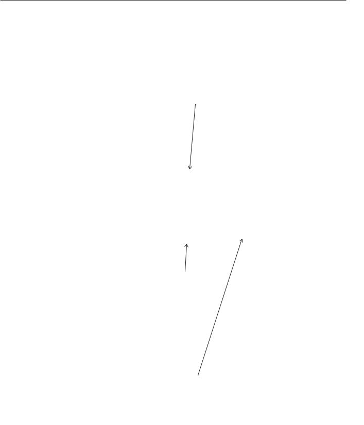
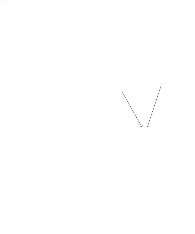
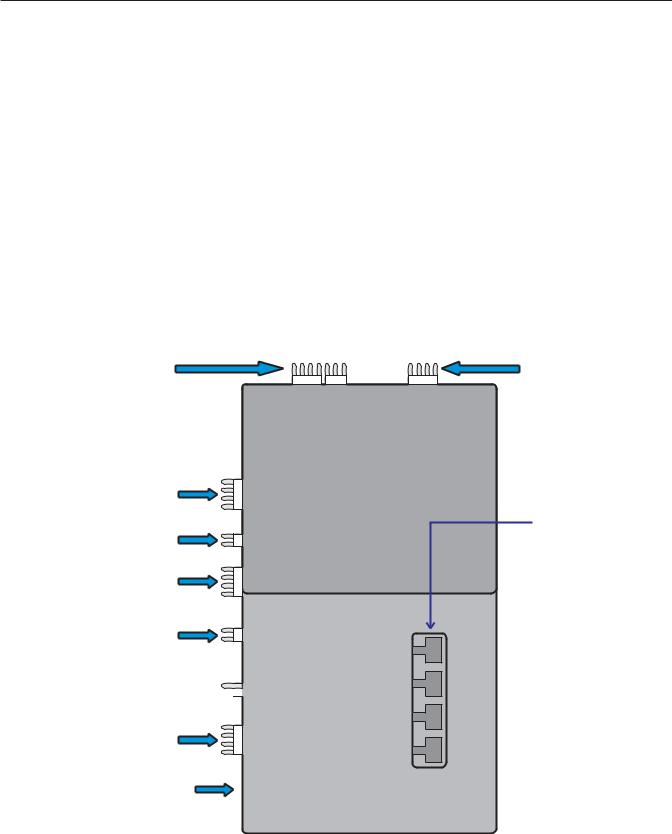
Air cooled models take room temperature air in from the left and right sides, and discharge warm air out the back. If installed in a corner or with another cabinet next to the right side, an air baffle could be installed on the back of the cabinet to minimize air re-circulation.
A 6 inch minimum clearance on the back, left and right sides is required for operation and service of this machine.
Air Flows in the Sides
and Out the Back
Note: Although the machine will function, ice capacity of air cooled machines will be significantly reduced with only 6 inches of clearance at the sides, back and top.
Unpacking and Assembly:
Begin with unpacking the ice storage bin. Remove the carton, and using part of the carton as a cushion, tip the bin on its back to remove the skid and attach the legs or casters. Note: Stacked applications may not use casters.
Return the bin to an upright position. Check the bin top gasket for gaps and tears, fill any in with food grade sealant prior to placing the ice machine on the bin.
If the ice machine has not been unpacked, do so now. Remove the carton from the skid. Lift the ice machine off the skid directly onto the bin.
Note: The machine is heavy! Use a mechanical hoist if necessary.
Secure the ice machine to the bin with the hardware provided (two metal straps and 4 bolts).
Cabinet Panel Removal:
Note: The top panel holds the upper edges of the side panels in place.
1. Front Panel, “A” series: Remove the front panel by removing the four screws connecting the front panel to the left and right sides.
Remove
Second
Remove
First
Removal of Panels
Front Panel “C thru H” Series: Remove top two screws, and pull the bottom of the panel away from the machine to unsnap it from the machine.
2.Remove 2 screws at the front edge of the top panel, and pull the top panel forward until it releases from the tabs connecting it to the back panel.
3.Remove the screws at the front edge of each side panel, and pull them forward until they release from the tabs connecting them to the back panel.
July 2007
Page 4
CME256, 506, 656, 806: AutoIQ™ Cubers
Stacking:
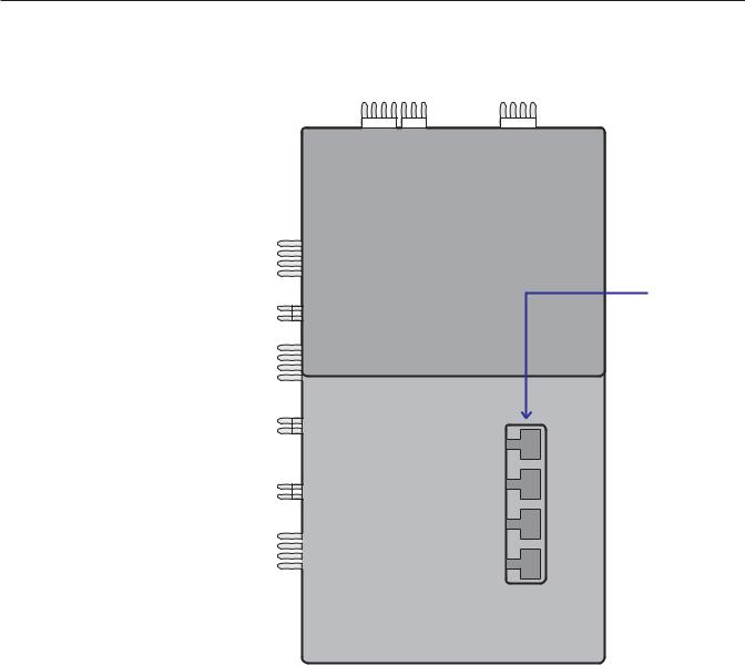
Models CME256, CME506, CME656 and CME806 may be stacked together in any combination. Use kit number KSCME6-30:
1.Remove the front, left side and top panels from the bottom machine. Discard the top panel.
2.Remove the front and left side panels from
the top machine.
3. Place the upper machine onto the lower |
Mounting Strap, |
Machine to |
|
machine. Check that the tabs on the top of the |
Machine |
freezing compartment in the lower machine |
|
engage the slot in the base of the upper |
|
machine (around the cube port). |
|
4. Fasten the upper cabinet to the lower |
|
cabinet with the hardware (two metal straps |
|
and four bolts) provided with the machine. |
|
5. Knock out 1 hole in the upper left (viewed |
|
from the front) corner of the lower unit’s back |
|
panel. Knock out the hole in the lower left |
|
(viewed from the front) corner of the upper |
|
unit’s back panel. |
|
6. Position the strain reliefs over the wrapped |
|
portion of the stacking kit wire harness. |
|
Route the Stacking Kit Wire Harness from the |
|
back to the top and bottom machines thru the |
|
holes made in step 5. The harness is marked |
|
which end goes to which machine. Push the |
|
strain reliefs into place from the back of the |
|
machines. |
Mounting Strap, |
|
|
Follow local electrical codes for 24 volt wire. |
Machine to Bin |
|
|
In the lower unit, route the wire behind the |
|
suction line and thru the snap bushing just |
|
below the Controller. Tape any excess wire to |
|
the insulated suction line. |
|
In the upper unit, route the harness thru the |
|
snap bushing just below the System |
|
Controller. |
|
Plug one end into each Controller connection
number 7. Wire Harness from
Stacking Kit
7.Place insulation pad from the kit over the reservoir drain tubing in the upper machine. Make certain that the insulation is in contact with the tubing.
8.Return all panels to their normal places.
Stacking Like Models
July 2002
Page 5

CME256, 506, 656, 806: AutoIQ™ Cubers
Plumbing:
All models require an adequate potable water supply and a gravity drain. The recommendations for tubing are: Water supply to be 3 8“ OD. Drain to be ¾ “ OD.
Supply:
Drain:
Air cooled models have 1 gravity drain connection, a ¾ “ FPT fitting at the back of the cabinet.
It must be vented at the back of the cabinet.
Air cooled models have 1 water supply connection, a 3 8“ male flare at the back of the cabinet. Water cooled models have an additional 3 8” FPT condenser inlet connection at the back of the cabinet.
Potable Water |
Water Cooled |
|
Plumbing |
||
Inlet |
||
Connections |
||
|
Condenser
Water Inlet
Water cooled models have an additional condenser drain, it is a ½ “ FPT fitting at the back of the cabinet. Do not vent this drain.
The ice storage bin will have a drain out the back or base, depending upon the model. Note: Scotsman HTB555 (shown in this manual) may be drained either out the back or the base.
Condenser
Drain
Potable
Water Inlet
Optional
Filter
Reservoir 
Drain, Must
Be Vented
Separate
Drains for
Bin and
Machine
Plumbing
Connections
HTB555
Drains
Insulation is recommended for the ice machine reservoir and bin drains.
Follow all applicable codes
July 2002
Page 6
CME256, 506, 656, 806: AutoIQ™ Cubers
Electrical:
All models must be installed with the correct wire size and type per the National Electric Code. Locate the nameplate on the back of the cabinet and find the numbers for Voltage, Phase, Minimum Circuit Ampacity and Maximum Fuse Size. Either fuses or HACR type circuit breakers may be used.
Electrical connections are made in the junction box in the back of the cabinet.
1.Remove the junction box cover.
2.Knock out 1 hole for a field supplied strain relief.
3.Install wires and strain relief per code.
4.Connect to wires and secure ground wire to
ground screw inside junction box. |
Junction Box |
|
Electrical Access
Follow all Local, State and National codes.
Electrical Connection
July 2002
Page 7

CME256, 506, 656, 806: AutoIQ™ Cubers
After Utility Connections:
1.Level the cabinet, use the leg levelers on the end of the legs to adjust the cabinet height.
2.Wash out the bin. If desired, the interior of the bin could be sanitized.
3.Locate the ice scoop (if supplied) and have it available for use when needed.
Final Check List:
1.Is the unit located indoors in a controlled environment?
2.Is the unit located where it can receive adequate cooling air?
3.Has the correct electrical power been supplied to the machine?
4.Have all the water supply connections been made?
5.Have all the drain connections been made?
6.Has the unit been leveled? The unit must be leveled at the water reservoir.
7.Have all unpacking materials been removed?
8.Is the water pressure adequate?
9.Have the drain connections been checked for leaks?
10.Has the bin interior been wiped clean or sanitized?
11.Have any water filter cartridges been replaced?
July 2002
Page 8

CME256, 506, 656, 806: AutoIQ™ Cubers
Component Location and Function:
Reservoir: Contains the water charge used for every batch of ice.
Water Inlet Valve: Opens to allow water into the reservoir.
Water Level Sensor: Controls the size of the ice cube by measuring how much water is used in a cycle. It consists of a float, stem and electric eye. The stem will move slightly when the pump is on, this is normal. As the machine makes ice the reservoir water level will fall and the visible portion of the stem will slide down thru the slot in the sensor body.
AutoIQ Controller: Controls the complete operation of the ice machine. Turns it on and off; switches it between cycles; shows information via indicator lights; and shuts the machine down if there is a problem.
Evaporators/Freezing Compartment: Location of the evaporators. Ice forms on the evaporators and is released when warmed up during the harvest cycle. The freezing compartment is fully insulated for maximum efficiency.
Cube Deflector: The slots in the inclined deflector let the water falling from the evaporators back into the reservoir, but when ice falls during harvest, the ice slides off into the bin.
Refrigeration Service Access Valves: Only to be used by a certified technician. Allows access to the refrigeration system for diagnostic information.
Water Pump: Forces the water from the reservoir to the top of the evaporator(s). The motor is separated from the reservoir water to minimize contact with the water.
Compressor: The refrigerant vapor pump, it forces the refrigerant to flow thru the refrigeration system tubing.
Hot Gas Valve: Closed during freeze, it opens during harvest to divert hot discharge refrigerant gas into the inlet of the evaporators.
Condenser: Either air or water cooled, discharges the heat produced in ice making.
Access Valves
AutoIQ
Controller
Evaporators
|
Cube |
Compressor |
Deflector |
Water Pump
Inlet Water
Valve
Water Level
Sensor
Reservoir
Component Location
July 2002
Page 9
CME256, 506, 656, 806: AutoIQ™ Cubers
AutoIQ Controller:
Indicator Lights:
•Bin Full: On when bin is full, goes on and off as ice falls during a harvest cycle.
•Freeze: On when the unit is in the Freeze cycle, blinks when a freeze mode is pending.
•Harvest: On when the unit is in the Harvest cycle.
•Clean: On when the unit is in the Clean cycle, blinks when preparing for a clean mode.
•Off: On when the unit has been switched off, blinks when the machine is preparing to shut off.
•Water Error: On when the controller has identified a problem with the water system.
•Refrigeration Error: On when the controller has identified a problem with the
refrigeration system.
Low Voltage In/out |
|
|
Water Valve |
|
|
Hot Gas Valve |
8 |
|
Contactor Coil |
||
|
Stacking |
7 |
Future Use |
6 |
Reservoir & Discharge |
5 |
Line Thermistors |
|
Bin Control Sensor |
4 |
|
Bin Control Sensor 
 3
3
Reservoir Water |
2 |
|
Level Sensor |
||
|
||
Factory Use |
1 |
Cycle Definitions:
•Freeze: The refrigeration system is operating to remove heat from the evaporators. The compressor, fan motor (if air cooled) and water pump are ON.
•Harvest: The refrigeration and water systems are operating to harvest the ice cubes. While the compressor is on for the full cycle, the water pump will be off at the beginning and inlet water valve will switch off before the end.
•Clean: The Inlet Water Valve opens to fill the reservoir, The Water Pump starts. The Clean indicator light is switched ON. A manually initiated rinse flushes the system.
|
Hi Voltage In/out |
|
Water Pump |
9 |
Air Cooled Fan Motor |
|
Push Button
Control Switches
Indicator Lights:
 BIN FULL

 FREEZE
 HARVEST
 CLEAN
CLEAN
 OFF
OFF
Diagnostic Lights
 WATER
WATER
 REFRIGERATION
AutoIQ Controller: Wire Connections, Push Buttons, and Indicator Lights
July 2002
Page 10
CME256, 506, 656, 806: AutoIQ™ Cubers
Initial Start Up:
1.Remove the front panel.
2.Locate the AutoIQ Controller.
3.Switch on the electrical power. Note that the indicator lights all flashed on briefly.
4.Open the water supply valve.
5.Push and release the Freeze cycle push button (the Freeze indicator light will blink until the compressor starts). The next several operations are automatic.
Initial Start Sequence
•The Freeze light is blinking.
•The Hot Gas Solenoid valve is open.
•The inlet water valve opens to fill the reservoir. The inlet water valve will shut off when the reservoir is full.
•The water pump starts to pump water.
•The inlet water valve opens again to refill the reservoir.
•After 30 seconds the compressor starts.
•After 5 seconds the hot gas valve closes.
Freeze Cycle:
•The Freeze indicator light will come on. The machine will stay in a Freeze cycle for many minutes. Slush may appear in the reservoir, it is temporary and normal.
•Under certain conditions, the pump may stop for a few seconds. After that the inlet water valve will refill the reservoir.
•The fan motor (of air cooled models) will begin to turn and soon warm air will be forced out the back of the cabinet.
•The freeze cycle will continue until the water level in the reservoir drops to its factory set point, then the Harvest Cycle will begin.
Harvest Cycle:
•The Harvest indicator light will be ON,
•The hot gas valve will open.
•The water pump will stop. It will restart in less than a minute.
•The Inlet water valve will open. The machine will fill the reservoir and overflow it for a specified number of seconds then shut off. The harvest cycle may still be in progress.
•The Bin Full indicator light will go on and off as ice falls from the evaporators.
6. Machines are shipped from the factory with the purge level set to accommodate average water conditions. See page 13 for purge adjustment instructions.
24 hours of run time may be need to attain full ice making capacity.
7.The machine’s correct cube size should result in ice falling from the evaporator in vertical strips of 8 - 10 cubes; the top 2 cubes might fall individually.
8.After a few minutes the machine will return to a freeze cycle.
9.Fill out the Customer Evaluation and Warranty Registration. Send it to Scotsman.
10.Replace the front panel.
11.Inform the user of the location and telephone number of the local service company. Also inform the user of the required maintenance of the machine.
Notes On Operation:
1.The electric eyes signal the ice machine to shut off whenever the bin becomes full. After the eyes sense that there is ice between them, the ice machine will shut off at the end of the next harvest cycle. This last harvest cycle will be longer than the rest.
2.After the bin has filled the ice machine will not be able to restart for 4 minutes. However, if needed, the Freeze button may be pushed and the unit will restart.
For example: If ice is removed from the bin immediately after the machine has filled up and shut off, the machine will not restart for 4 minutes.
3. If the bin controls sense a bin full signal before any water is used (float stem up), the machine will shut off on bin full.
July 2004
Page 11

CME256, 506, 656, 806: AutoIQ™ Cubers
Adjustments:
If there was a problem during Initial Start Up:
If an error light came on, check the following.
1. Water error.
A water error could have been determined by the System Controller if the inlet water valve does not fill the reservoir, or if the water pump does not start and lower the water level.
2. Refrigeration error.
A refrigeration error could have been determined by the System Controller if the water temperature did not drop during the freeze cycle. The controller will next check the compressor discharge temperature, If the discharge temperature is too low, the refrigerant error light will be switched on, and the machine will Shut Down.
Note: Reset and restart the machine by pushing and releasing the Off push button switch, and then pushing and releasing the freeze push button switch.
How to Adjust Cube Size (Reference Only)
The adjustment is done by moving the long screw located in the floating stem at the front of the machine.
Note: Units manufactured beginning 3/97 do not have a cube size adjustment screw; their cube size is fixed.
Cube Size
Adjustment
Screw
Adjustment of
Cube Size
1.Remove the front panel.
2.Locate adjustment screw, and
To increase the cube size, turn the screw out (counter clockwise)
To decrease the cube size, turn the screw in (clockwise)
Turn the screw 2 turns at a time.
3. Check cube size after the next freeze cycle, repeat step 2 if needed.
Cube Size Diagram
|
|
Side View, Cube |
Front View, |
|
|
should be 1/2" thick |
Cube is 1.5" x 1.4" |
at the center |
|
July 2002 |
|
Page 12 |
|
CME256, 506, 656, 806: AutoIQ™ Cubers
Adjustments:
How to adjust the water cooled discharge pressure
Water cooled models use a water regulating valve to control how much cooling water flows thru the water cooled condenser. At the top of that valve, located in the right rear corner of the ice machine, is an adjustment stem.
To Adjust:
1.Attach a refrigeration manifold gage to the discharge access valve.
2.While the unit is in the freeze cycle, determine the discharge pressure, it should be about 245 PSIG.
3.If needed, rotate the adjustment stem to increase or decrease the pressure:
Water
Regulating
Valve
Adjustment
Screw
Adjusting Water Cooled
Discharge Pressure
A.To increase discharge pressure (reduce water flow) rotate the stem counter-clockwise.
B.To decrease the discharge pressure (increase water flow) rotate the stem clockwise.
Remove the manifold when done. Note: The water outlet temperature should be between 100-110 when the valve is properly set.
Thermostatic Expansion Valve:
The TXV is not adjustable, do not attempt to adjust it.
How to Adjust the Amount of Water Purge
Adjustment is done by use of the control buttons on the AutoIQ Controller. Examine the next section to become familiar with the Controller before beginning.
1.If the machine is on, push and hold the OFF button for more than 3 seconds, then release it. This switches the machine Off.
2.Push and hold the OFF button for more than 3 seconds (just until all lights flash on) then release it. Do not hold it in it too long.
3.Examine the green lights. They should have all flashed once, then certain ones will have turned on to indicate which purge level the machine is set at. There are 5 levels of purge available:
•1. Maximum Purge is when All 5 lights are ON. Use for extreme water conditions. Note: This setting may extend the Harvest cycle and reduce capacity.
•2. Heavy Purge is when these 4 lights are ON: Freeze, Harvest, Clean, Off. Use for severe water conditions.
•3. Standard Purge (factory setting) is when these 3 lights are ON: Harvest, Clean, Off. Use for moderate to severe water conditions.
•4. Moderate Purge is when these 2 lights are ON: Clean, Off. This is for typical water conditions.
•5. Minimum Purge is when this light is ON: Off. For excellent water conditions.
Adjust by pushing and releasing the Freeze button. Pushing and releasing the Freeze button increases the purge one level up to the maximum, then it goes to the minimum.
4. The machine will automatically restart after 60 seconds of no switch inputs, or restart the machine by pushing in and holding the Off button for more than 3 seconds, then releasing it. The unit will then be Off. From there the machine may be placed in a freeze cycle by pushing and releasing the Freeze button.
July 2002
Page 13
CME256, 506, 656, 806: AutoIQ™ Cubers
How To Operate The AutoIQ Controller
The AutoIQ Controller is a |
|
|
|
|
microprocessor based device that |
|
|
|
|
receives input from several sources |
|
|
|
|
and switches various components on |
|
|
|
|
and off. |
|
|
|
|
Its manual control is thru the use of |
|
|
|
|
the Push Button Control Switches |
|
|
|
|
1. Freeze Button. Pushing and |
|
|
|
|
releasing this button starts or restarts |
|
|
|
|
the machine. The System Controller |
|
|
|
|
remembers what cycle it was last in |
|
|
|
|
and returns to that cycle. |
|
|
|
7 |
|
|
|
||
2. Harvest Button: Pushing and |
|
|
|
|
|
|
|
|
|
|
|
|
|
|
releasing this button will cause the |
|
6 |
||
machine to go directly to a Harvest |
|
|||
|
||||
Cycle. Can be done from Freeze or |
|
|
|
|
Off. The machine will switch Off at the |
|
|
|
5 |
|
|
|
||
end of the Harvest cycle. |
|
|
|
|
|
|
|
|
|
3. Clean Button: Pushing and |
|
|
|
|
releasing this button will cause the |
|
4 |
||
machine to only power the water |
|
|||
|
||||
pump for circulation of ice machine |
|
|
|
|
cleaner. After the ice machine |
|
|
|
|
cleaner has circulated for about 10 |
|
3 |
||
|
||||
minutes a second push of this button |
|
|||
|
|
|
||
will switch on the rinsing system to |
|
|
|
|
flush out the dissolved scale and ice |
|
|
|
|
|
|
|
|
|
machine cleaner. |
|
|
|
2 |
|
|
|
|
|
4. Off Button: Pushing and releasing |
|
|
this button will switch the machine |
1 |
|
OFF at the end of the next cycle. If the |
||
|
||
button is pushed and HELD for more |
|
|
than 3 seconds, the unit will switch off |
|
|
immediately. |
|
|
To Reset Machine (machine off, error |
|
|
light on): First push and release the |
|
|
Off button, then push and release the |
|
|
Freeze button. |
|
To Recall the last two diagnostic codes: Push and hold the Off button until the machine shuts off. Then push and hold the Off button again until the green lights flash on. Push and release the Harvest button to recall the most recent diagnostic code. Push and release the Harvest button again to recall the second to last diagnostic code (the bin full light will be on when the second to last code is displayed). If no code is displayed, there was none recorded. Push and release the off button again to return to the normal setting.
8 9
Push Buttons
Indicator Lights
 BIN FULL

 FREEZE
 HARVEST
 CLEAN
CLEAN
 OFF
OFF
Diagnostic Lights:
 WATER
WATER
 REFRIGERATION
Controller Indicator Light Description
July 2004
Page 14

CME256, 506, 656, 806: AutoIQ™ Cubers
How The Electronic Cuber Works
This section is intended for the technician. It is not |
Refrigeration System: |
|
necessary for the normal operation and |
The refrigeration system is similar to that of most |
|
maintenance of the machine. |
||
commercial cube ice machines. Heat is removed |
||
|
||
The AutoIQ Controller operates the ice machine by |
from the water and discharged out the condenser |
|
monitoring several input measures and switching |
during the freeze cycle. As liquid refrigerant |
|
passes thru the Thermostatic Expansion Valve(s), |
||
various loads on and off. |
||
it enters the bottom of the evaporators, and will |
||
|
||
Water System: |
form on the bottom first. Later CME506 models |
|
have check valves to help direct the flow of |
||
Water flows into the ice machine during the |
||
refrigerant to the correct distributor. |
||
harvest cycle thru the inlet water valve. The water |
||
|
||
valve will NOT be open the complete length of the |
When cubes need to be released (Harvest) the |
|
harvest cycle. The water pump forces water to the |
Hot Gas Bypass Valve is opened and hot |
|
top of the evaporators, both in the Freeze and |
discharge gas flows directly from the compressor |
|
Harvest cycles. Un-frozen water falls thru the cube |
to the evaporator inlets. This warms up the |
|
deflector and back into the reservoir. As water is |
evaporators and the surface of the ice frozen to |
|
turned into ice, the water level in the reservoir falls, |
the evaporator surface melts. Ice then falls into the |
|
and at the point where the cubes are fully formed, |
bin. |
the Water Level Sensor indicates to the Controller |
|
Thermostatic |
|
that it is time to begin the Harvest cycle. |
Hot Gas Valve |
||
Expansion Valve |
|||
|
|
||
During the Harvest cycle, water again enters the |
|
|
|
water reservoir, and overfills it to rinse the |
|
|
|
reservoir of accumulated |
|
|
|
NOT overflow for a |
|
Water |
|
time, but for a time |
|
||
|
Distributors |
||
the Controller. |
|
|
|
The water pump will |
|
|
|
for a short period of |
|
|
|
time at the beginning |
|
Evaporators |
|
of harvest. |
|
||
|
|
|
Cube |
Compressor |
Deflector |
Water Cooled
Condenser
Reservoir
Drain
|
Inlet Water Valve |
|
Water Pump |
|
|
|
Water and Refrigeration |
|
July 2007 |
Schematic - Note: CME506 E Has |
|
Two Expansion Valves |
||
Page 15 |
||
|

CME256, 506, 656, 806: AutoIQ™ Cubers
Technicians Only: Freeze Cycle Operational Sequence
Assuming the machine has been operational, the Freeze cycle begins with the end of the Harvest Cycle:
•Reservoir is full
•Condenser fan is OFF
•Water Inlet Valve is OFF
•Water Pump is ON
•Compressor is ON
•Hot Gas Valve is ON
Controller Operation, Beginning freeze:
1.Switches on the Freeze indicator light and shuts off the hot gas valve.
2.Measures and stores the discharge temperature.
3.Starts the fan motor (air cooled only). Some early units have a fan control switch, it shuts the fan off if the discharge pressure drops below 190 PSIG. Machines built beginning in August 1996 do not have a fan control switch, instead the Controller checks the discharge temperature and
cycles the fan every 30 seconds if the temperature is low (below 125oF. or more than 3381 ohms).
If the discharge temperature exceeds the design maximum (250oF. or less than 377 ohms), shuts the machine down on a Refrigeration Error.
4.Checks for a “bin full" signal throughout the cycle.
5.Measures the reservoir water temperature. If the machine is operating correctly, the reservoir water temperature will fall at a standard rate. The Controller will be checking to see if the water temperature fall matches that rate.
If not, it re-checks the discharge line temperature. If too low, it Shuts Down on a Refrigeration Error. If the discharge temperature is acceptable, the water system is checked by shutting off the water pump and determining if the water level goes up enough. If it does not, it is assumed that there is a water pump problem and the machine Shuts Down on a Water Error.
If the water level does “measure up" the water pump is restarted and the controller then measures how long it takes to lower the water level. If the water level does not fall, the machine Shuts Down on a Water Error.
6.Once per cycle the machine may shut off the
water pump. It only does this when the water temperature reaches a preset minimum (38oF. or 27835 ohms). The pump will only be off for a few seconds. After the pump restarts, the inlet water valve opens to refill the reservoir.
7.As the machine makes ice, the water level in the reservoir will ultimately fall to the Harvest Level (when the top electric eye in the water level sensor is disrupted by the adjustment screw).
Note: If the freeze cycle exceeds the preset Maximum (50 minutes), the Controller will Shut Down on a Refrigeration Error.
8. The end of Freeze cycle will see the machine in this state:
•Water level = below harvest position
•Condenser fan will be off
•Water inlet valve will be off
•Water pump will be ON
•Compressor will be ON
•Hot gas valve will be off
At this point Harvest begins and the Controller switches the Harvest indicator light ON.
Note: If there is a power interruption, the system controller will automatically restart the machine with a process that begins with getting the machine back to a normal state: water re-fills, the unit freezes for 30 seconds and then goes into a 4 minute harvest. It will then proceed to a new Freeze cycle. While in an electrical restart mode, the controller’s Freeze light will be blinking - even when the machine is in harvest.
July 2002
Page 16

CME256, 506, 656, 806: AutoIQ™ Cubers
Technicians Only: Harvest Cycle Operational Sequence
Harvest
The (air cooled model) fan is off.
The water valve opens and fills the reservoir to the Full level.
The water pump shuts off, it will restart in less than a minute.
Note: Machines built after August 1996:
•If the machine remains in the harvest cycle for longer than between 6 to 9 minutes (depending upon the regular harvest cycle’s length) the water pump will be switched off until the next freeze cycle.
•When the bin is full and the unit is in a harvest cycle, the pump will be switched off.
The Controller checks how long it takes to fill the reservoir and if it was too much time, the machine Shuts Down on Water Error.
Note: The machine will automatically attempt to restart after shutting down because of a lack of water. The time between restarts is about 20 minutes.
The inlet water valve will stay on and open for a predetermined fraction of the time it took to fill the reservoir. This overflows and rinses the reservoir water.
During the Harvest Cycle, ice will be falling from the evaporators and between the bin control’s electric eyes. The Controller monitors the ice falling and stays in the Harvest Cycle until ice quits going thru the electric eyes.
The maximum harvest time is 10 minutes. The first Harvest after a restart will be a long one to establish a base line, then the actual time it took to release the ice is used to determine the length of the next harvest cycle.
If no cubes fall (or are sensed) by the end of Maximum Harvest Time, the machine senses a refrigeration error. If the next cycle also produces a refrigeration error, the machine Shuts Down.
Note: Machines built up to August 1996: The last Harvest cycle before shutting off on Bin Full will be 10 minutes long. Machines built beginning
August 1996 have a last harvest cycle that is 4-6 minutes long.
Note: The machine will not restart for 4 minutes after switching off on Bin Full, unless the freeze button is pressed.
Stacked Units:
If the bottom unit is in harvest and receives a signal from the top unit that it is also in Harvest, the bottom unit will stay in harvest for its Maximum Harvest Time.
Diagnostic Lights and Manual Resets
The controller will shut the machine off if a malfunction is sensed. Controllers up to 17-1 will shut the machine off after the first malfunction. Controllers marked 17-1 and up will restart the machine 2 times, with a 50 minute interval between restarts.
If a malfunction is still present after the second restart, the machine will then shut off and must be manually reset. During the restart interval, the machine will be off and a diagnostic code indicated.
An exception to this is lack of water. When switched off because of lack of water, the machine will always try to re-fill the reservoir every 20 minutes.
Another exception is a harvest error. As before, there must be two consecutive harvest errors to trigger a machine shut-down. With this change, the controller will still shut down and restart the machine after two consecutive harvest errors. However, if the errors repeat two more consecutive times, the controller will shut down and restart the machine again. If the machine registers two more consecutive harvest errors, the machine will again shut down and must be manually reset.
Production of units with Controllers 17-1 began approximately March 1997. Higher numbers may be expected after that date.
July 2002
Page 17
 Loading...