


Service Manual for
Cube Ice Machine with storage models CU0415, CU0715 and CU0920

Service Manual for Models CU0415, CU0715 and CU0920
Introduction
The design of this product is the result of years of experience in developing commercial ice cube
machines. It has been designed for simple operation in a wide range of locations. Please follow the instructions for installation and maintenance to get the most use from this ice machine.
Table of Contents
Important Details. . . . . . . . . . . 2 Pre-Installation. . . . . . . . . . . . . . . . . . . . . . .3
Cabinet Layout, CU0415 and CU0715. . .4
Cabinet Layout, CU0920. . . . . . . . 5
Component Location. . . . . . . . . .6 Connect the water supply. . . . . . . .7 Connect the power . . . . . . . . . . 8 Control Panel and Adjustments. . . . . .9
Initial Start Up. . . . . . . . . . . . 10
Use and Operational Notes. . . . . . . 11 Maintenance. . . . . . . . . . . . .12 Electrical Sequence. . . . . . . . . 14
Components . . . . . . . . . . . . .15
Performance. . . . . . . . . . . . .16
Thermistor Values. . . . . . . . . . .17 Controller Use. . . . . . . . . . . . 18
Anti-Slush . . . . . . . . . . . . . .19
Service Diagnosis. . . . . . . . . . .21
Service Diagnosis. . . . . . . . . . .22 Service Diagnosis. . . . . . . . . . .23 Removal and Replacement. . . . . . . 24 Removal and Replacement. . . . . . . 25
Removal and Replacement. . . . . . . 26
Controller.. . . . . . . . . . . . . 27 Cabinet Removal for Service. . . . . . 28 115/60/1 Wiring Diagram.. . . . . . . 29
Observe the Caution and Warning notices. They are indicators of important safety information. Keep this manual for future reference.
August 2013
Page 1
Service Manual for Models CU0415, CU0715 and CU0920
Important Details
The machine is designed for use indoors in a controlled environment. It must be kept dry, not overheated or subjected to excessive cold. The water and power supply must be maintained or the machine will stop making ice.
There are limits to how hot or cold the room it’s in can be.
•Minimum air temperature: 50oF or 10oC
•Maximum air temperature: 100oF or 38oC.
There are also limits to how hot or cold the water supply can be:
•Minimum water temperature: 40oF or 4.5oC
•Maximum water temperature: 100oF or 38oC.
There are limits to the voltage supply to the unit, voltages vary by model:
Voltage
|
115 (-1) |
Minimum |
104 |
Maximum |
126 |
Water supply must be potable by the localities definition.
There are limits to the water pressure supplied to the unit:
•Maximum pressure. static: 80 psi or 5.5 bar
•Minimum pressure, dynamic: 15 psi or 1 bar
A drain will be needed for melted ice and rinse water.
Warranty:
The warranty statement for this product is provided separately from this manual. Refer to it for applicable coverage. In general warranty covers defects
in material or workmanship. It does not cover maintenance, corrections to installations, or situations when the machine is operated in circumstances that exceed the limitations printed above.
This is a commercial model, if installed in a residence some commercial service companies may not be able to service it on site.
The manufacturer has designed and produced this machine with the finest in materials. The manufacturer assumes no liability for units that have been altered in any way. Alterations or part substitutions will void the warranty. Specifications and designs are subject to change without notice.
Options:
There are two floor mounting kits available:
•KUFM15: for 15” models
•KUFM20: for 20” model
Bottom of Cabinet, showing bumper. Cabinet height includes bumper.
August 2013
Page 2
Service Manual for Models CU0415, CU0715 and CU0920
Pre-Installation
This appliance is intended to be used in commercial applications including:
•Restaurant kitchens
•Bars
•Hotels
Dimensions and Electrical:
Spacing:
No additional spacing is required at the top or sides. However, suggested minimum side clearance for installation is 1/8 inch or 3 mm and suggested minimum top clearance is 1/4 inch or 7 mm.
Allow 4 inches (100 mm) minimum space at the back for the utility connections. Do not block louvers at the front of the cabinet.
Model |
Electrical |
Width |
Depth |
Height (w/o legs) |
Total Load |
|
(volts/Hz/Phase |
(in / cm) |
(in/cm) |
(in/cm) |
Amps |
CU0415MA-1A |
115/60/1 |
15 / 38 |
23.7 / 60.3 |
31.94 / 81.1 |
8 |
CU0715MA-1A |
115/60/1 |
15 / 38 |
23.7 / 60.3 |
31.94 / 81.1 |
8 |
CU0920MA-1A |
115/60/1 |
20 / 51 |
23.7 / 60.3 |
31.94 / 81.1 |
8 |
Location:
The unit can be built into a cabinet as the air flow is in and out the front. The front of the machine must not be blocked. Certain maintenance or repair procedures will require removal of the top, back and side panels, so plan ahead for service and maintenance needs.
Air IN
Unpacking and setup
Remove all shipping and packing materials that may be in the ice storage bin.
The unit can be installed with or without legs. The cabinet is equipped with small bumpers on the base to allow placement without legs. An optional floor mounting kit is also available to fill the gap between the machine and floor if not using legs. If using legs, carefully tip the machine and install the legs by screwing them into the leg sockets in the bottom of the machine. For reference, the thread size is 5/8 –
11. If the machine has been tipped onto its side or back allow 1 hour before starting the unit for the oil in the refrigeration system to return to the compressor.
Place the machine in its intended location and level it front to back and left to right. If using legs, adjust their feet in and out to level the cabinet.
If legs are not used the bottom edges of the cabinet must be sealed to the floor.
If built into a cabinet, the adjacent cabinet walls will provide the means for containment. There are no means for attachment to the cabinet.
Be sure to remove the plastic covering the exterior panels, if left on it will be much harder to remove later.
 Air OUT
August 2013
Page 3
Service Manual for Models CU0415, CU0715 and CU0920
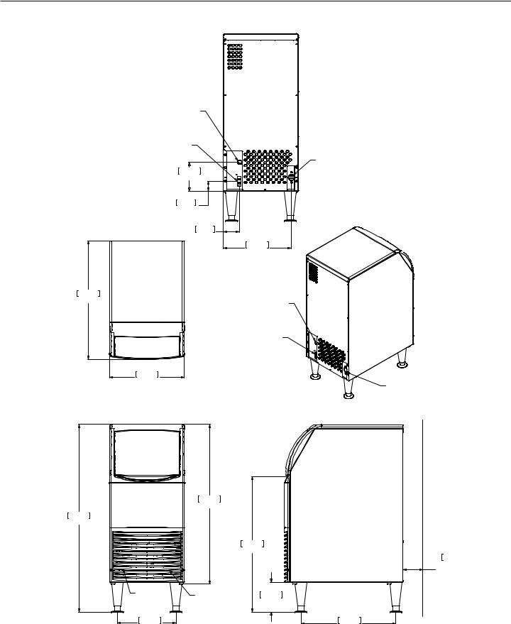
Cabinet Layout, CU0415 and CU0715
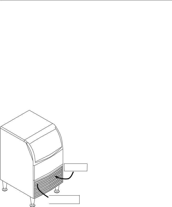
POWER CORD
POTABLE
WATER INLET 1/4" OD. PLASTIC TUBING (5ft)
14.6cm
5.8in
5.1cm
2.0in
8.2cm
3.2in
60.3cm
23.7in
38.1cm
15.0in
81.1cm
31.9in
95.4cm
37.6in
AIR |
AIR |
|
OUTLET |
||
INLET |
||
|
||
29.8cm |
|
|
11.8in |
|
DRAIN 3/4" FPT
34.5cm
13.6in
POWER CORD
POTABLE
WATER INLET 1/4" OD. PLASTIC TUBING (5ft)
DRAIN 3/4" FPT
68.9cm
27.1in
M
CLE
15.2cm
6.0in
48.3cm
19.0in
August 2013
Page 4
Service Manual for Models CU0415, CU0715 and CU0920
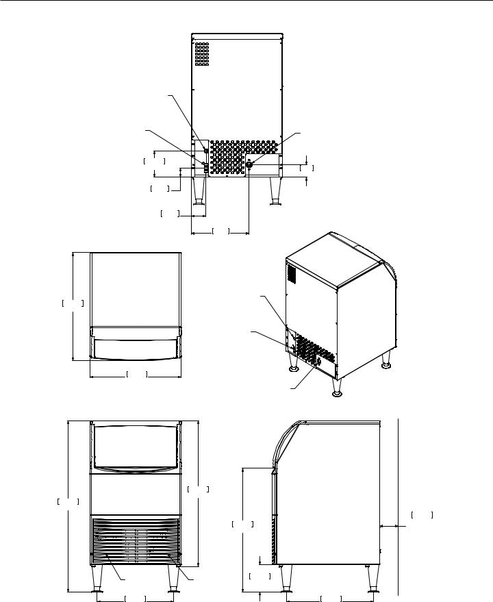
Cabinet Layout, CU0920
POWER CORD
POTABLE
WATER INLET 1/4" OD. PLASTIC TUBING (5ft)
14.6cm
5.75in
5.1cm
2.00in
8.2cm
3.23in
60.1cm
23.67in
50.8cm
20.00in
81.1cm
31.94in
95.4cm
37.56in
AIR |
AIR |
OUTLET |
INLET |
42.5cm |
|
16.75in |
|
DRAIN 3/4" FPT
7cm
2.75in
32cm
12.60in
POWER CORD
POTABLE
WATER INLET 1/4" OD. PLASTIC TUBING (5ft)
DRAIN 3/4" FPT
68.9cm
27.13in
15.2cm
6.00in
48.3cm
19.00in
10.2cm
4.00in MINIMUM UTILITY CLEARENCE
August 2013
Page 5

Service Manual for Models CU0415, CU0715 and CU0920
Component Location
Cube Deflector
Curtain
Bin
Thermostat
Sensing
Point
Thermostat
Condenser Fins
Drain Plug
 Bin Thermostat Adjustment
Controller
Control Area
Condenser Fan
August 2013
Page 6
Service Manual for Models CU0415, CU0715 and CU0920
Connect the water supply
Plumbing information:
•The water supply connection is at the back panel. It is a 5’ (1.5 meter) 1/4 inch (6.35 mm) OD plastic tube.
•A hand actuated valve within site of the machine is required to isolate the unit when it’s being serviced.
•The machine has a built-in back flow preventer (an air gap between the end of the water inlet hose and the top of the reservoir water), no additional back flow preventer is needed.
•Water flow rate into machine is .25 GPM / .94 LPM.
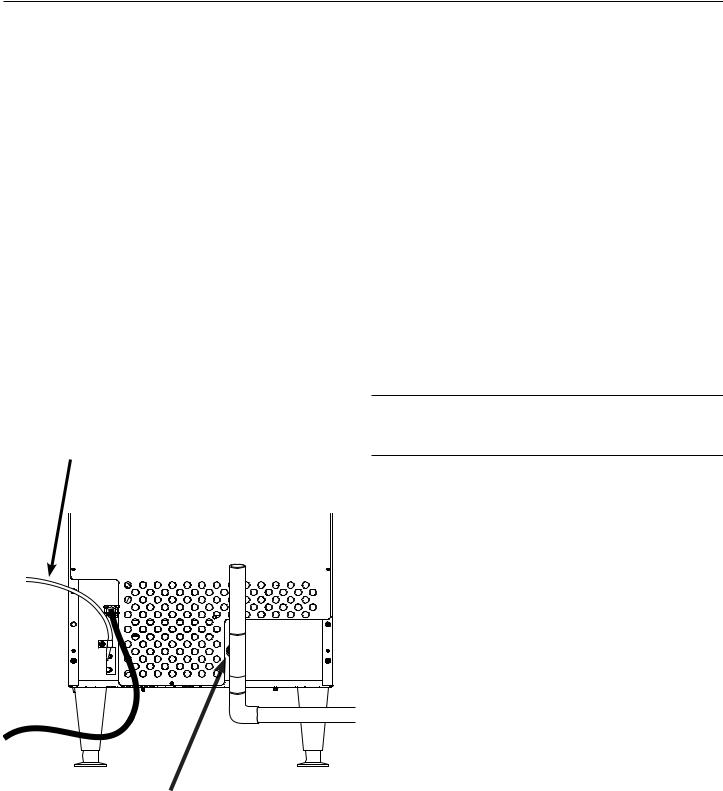
Units that are built into a cabinet:
Include a loop or coil of tubing between the water supply and the connection on the ice machine. When the machine is pushed back into the cabinet the tubing will coil and not kink.
Potable Water Inlet Tube
Drain Fitting, 3/4 FPT
Connection Information:
WARNING: connect to potable water supply only.
Important: Open the hand water valve to flush water through the connection point before connecting to the ice machine.
1.Cut cable ties securing hose and power cord to unit.
2.Connect to cold, potable water using the necessary adapters for the 1/4 inch OD plastic tube.
•If using compression fittings they require a ferrule or sleeve and insert.
•A female 3/8 compression adapter x 1/4 OD compression allows connection to a typical 3/8 OD compression angle valve.
•Another connection method is by quick connect fittings.
Note: Do not use a piercing-type saddle valve to connect to the building’s water supply. Valves of that type restrict water flow and clog easily.
Connect the drain
The drain connection is at the back panel. The fitting size is ¾ FPT.
1.Connect rigid tubing to this fitting and vent it at the machine, use an 8 inch or 200 mm vertical tube for the vent.
2.Slope drain tubing down from the ice machine to the building drain and the slope must be at least ¼ inch per foot or 20 mm per meter.
3.Insulate the drain tubing to reduce condensation and is recommended for environments that have high humidity.
Due to the potential for leaks, condensate pumps are not recommended.
August 2013
Page 7
Service Manual for Models CU0415, CU0715 and CU0920
Connect the power
This is a cord-connected unit, and must be connected to its own dedicated power supply. Check the dataplate on the back of the machine to confirm the voltage and per the dataplate use fuses or HACR circuit breakers.
Power Cord:
This 115 volt model is equipped with a cord and 5-15P plug.
Follow All Local Codes - This Unit Must Be Grounded. Do not use extension cords and do not disable or by-pass ground prong on electrical plug.
Plug the power cord into the proper power supply.
Installation check list
•Has the machine been installed indoors in an environment suitable for it?
•Have all of the shipping items and packaging been removed?
•Has the plastic covering the exterior panels been removed?
•Is the ice chute in the correct position?
•Is the clear plastic curtain hanging down and free to move?
•Has the water supply been connected and confirmed to not leak?
•Has a properly sized and sloped drain tube been attached?
•Has the correct voltage power supply been connected?
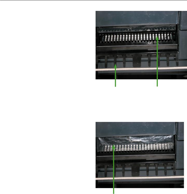
Front view of freezing compartment, right arrow points to Spray Platform, under the Cube Deflector. Push curtain back and check that it is in this position.
Left arrow points to Cube Deflector, it must be positioned as shown, it snaps onto front edge of reservoir. Remove any packing materials.
Curtain
Front view of freezing compartment, arrow points to clear plastic curtain. After checking spray platform, pull curtain down to hang freely. This is its normal position.
August 2013
Page 8
Service Manual for Models CU0415, CU0715 and CU0920
Control Panel and Adjustments
Ice Bridge Thickness Adjustment Area
Ice Bridge Thickness Adjustment |
ON / OFF / WASH |
||
Réglage de l'épaisseur du pont de glace |
MARCHE / ARRÊT / LAVAGE |
||
Ajuste del espesor del puente de hielo |
ENCENDIDO / APAGADO / LAVADO |
||
Regolazione spessore ponte di ghiaccio |
ON / OFF / LAVAGGIO |
||
EIN / AUS / WASCHEN |
|||
Anpassung der Eisbrückendicke |
|||
|
|||
- |
+ |
|
|
|
|
Harvest Time Adjustment |
|
|
|
Réglage du temps de récolte |
|
- |
+ |
Ajuste del tiempo de cosecha |
|
Regolazione orario di raccolta |
|||
Anpassung der Erntezeit |
|||
|
|
Freeze Mode |
|
|
|
Mode de congélation |
|
|
|
Modo de congelamiento |
|
|
|
Modalità congelamento |
|
|
|
Gefriermodus |
|
|
|
Timer On |
|
|
|
Minuterie allumée |
|
|
|
Cronómetro encendido |
|
17-3386-01 |
|
Timer attivato |
|
|
Timer eingeschaltet |
||
Master Switch. Move to ON (left side depressed) to make ice, OFF (centered) to shut off and WASH (right side depressed) for use in cleaning.
Harvest Time Adjustment Area
Indicator Light Area.
Freeze Mode light is ON when unit is in a Freeze cycle.
Timer On light is ON when trigger point temperature is reached in Freeze or Harvest.
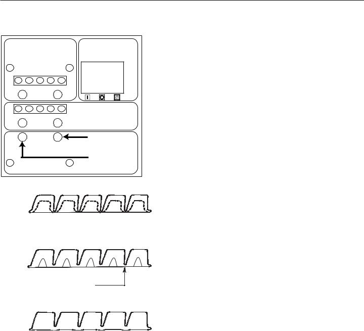
Ice Thickness Diagram |
Ice Bridge Thickness Adjustment |
Ice Too Thin
Ice Just Right
Bridge Thickness
Ice Too Thick
Adjustment Indicator Lights
Each push and release of the + or - button will change the lights that glow or blink indicating a change in ice size or harvest time. Example: pushing + one time changes a blinking light to steady on type. If the lights are on steady a single push of + will add one more light to the right and it will blink. There are 10 settings. All 5 lights on steady is the maximum setting and one blinking light is the minimum.
Refer to the Ice Thickness Diagram for proper ice size.
Adjust by pushing the + sign or – sign on the ice bridge adjustment section of the control panel. Changing bridge thickness should be a one-time adjustment as the machine will automatically maintain that ice thickness.
Harvest Cycle Time Adjustment
After ice has formed in the inverted mold, it must be released so it can be deposited in the storage bin section. The harvest cycle is when that occurs, and must be long enough for the ice to release. While the harvest cycle length is self adjusting it can also be manually adjusted if needed.
Proper harvest time is when the ice falls into the bin and there is about 10 seconds extra harvest time (pump and fan are off) before the freeze cycle restarts.
If the harvest time is too short to release the ice, the time may be increased by pushing the + sign on the harvest time adjustment section of the control panel. Operate the machine for another cycle to
confirm that the adjustment was correct. Note that too much harvest time will slightly decrease making ice capacity.
August 2013
Page 9
 Loading...