


CS60
INTRODUCTION
This service manual covers the installation, operation, maintenance and service of this ice machine.
Table of Contents
INTRODUCTION . . . . . . . . . . . . . . . . . . . . . . . . . . . . . . |
Page 1 |
SPECIFICATIONS . . . . . . . . . . . . . . . . . . . . . . . . . . . . . . |
Page 2 |
FOR THE INSTALLER . . . . . . . . . . . . . . . . . . . . . . . . . . . . |
Page 3 |
FOR THE PLUMBER . . . . . . . . . . . . . . . . . . . . . . . . . . . . . |
Page 4 |
INSTALLATION . . . . . . . . . . . . . . . . . . . . . . . . . . . . . . . |
Page 5 |
INITIAL START UP . . . . . . . . . . . . . . . . . . . . . . . . . . . . . . |
Page 6 |
HOW IT WORKS: COMPONENT DESCRIPTION . . . . . . . . . . . . . . . . . . |
Page 7 |
COMPONENT LOCATION . . . . . . . . . . . . . . . . . . . . . . . . . . . |
Page 8 |
HOW IT WORKS: WATER . . . . . . . . . . . . . . . . . . . . . . . . . . . |
Page 9 |
HOW IT WORKS: REFRIGERATION . . . . . . . . . . . . . . . . . . . . . . |
Page 10 |
HOW IT WORKS: REFRIGERATION . . . . . . . . . . . . . . . . . . . . . . |
Page 11 |
OPERATION & ADJUSTMENT: OPERATING CHARACTERISTICS . . . . . . . . . . |
Page 12 |
SANITIZING AND CLEANING . . . . . . . . . . . . . . . . . . . . . . . . . |
Page 13 |
SERVICE DIAGNOSIS . . . . . . . . . . . . . . . . . . . . . . . . . . . . |
Page 14 |
SERVICE DIAGNOSIS . . . . . . . . . . . . . . . . . . . . . . . . . . . . |
Page 15 |
REMOVAL AND REPLACEMENT . . . . . . . . . . . . . . . . . . . . . . . . |
Page 16 |
REMOVAL AND REPLACEMENT . . . . . . . . . . . . . . . . . . . . . . . . |
Page 17 |
Service Parts lists and Wiring diagrams are located in the center of this manual, printed on yellow paper.
This manual was printed on recycled paper.
Keep this manual for future reference.
Note the Warning symbol, it marks a possible hazard.
January 1995
Page 1
CS60
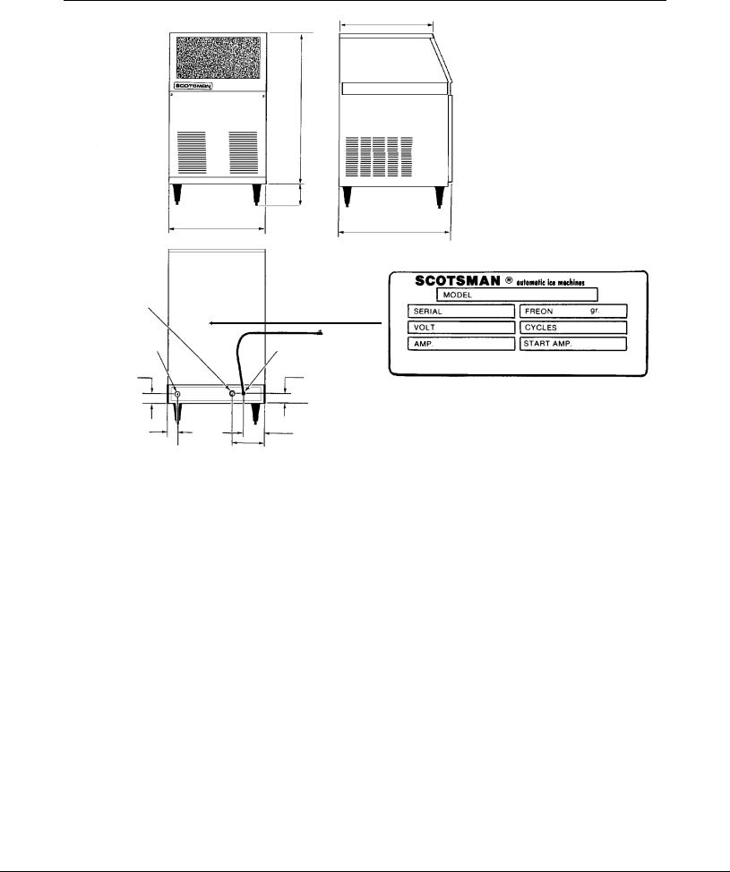
SPECIFICATIONS
17 9/16"
28.42"
|
5.5" |
18" |
20.6" |
|
NAMEPLATE LOCATION |
3/4" HOSE COUPLING |
|
THREAD |
|
25/32" |
POWER |
2 .2" |
2 .2" |
1 .76" |
3.83" |
|
5 |
.4"
SPECIFICATIONS
Model Number |
Dimensions |
Cube |
Basic |
Max. |
|
H" X W" X D" |
Size |
Electrical |
Fuse |
|
|
|
|
Size |
CS60MAS-1A |
28.42 X 18 X 20.6 |
Medium |
115/60/1 |
15 |
|
|
|
|
|
The finish is stainless steel. Minimum circuit ampacity is used to determine wire size per national electric code. Refrigerant type is R-22.
OPERATING REQUIREMENTS:
Refrigerant Charge is 12 oz of R-22. Always go by the namepate.
|
MINIMUM MAXIMUM |
|
Air Temperature |
500 F. |
1000 F. |
Water Temperature |
400 F. |
1000 F. |
Water Pressure |
20 PSIG |
100 PSIG |
Voltage |
103.5V |
126.5V |
Scotsman Ice Systems are designed and manufactured with the highest regard for safety and performance. They meet or exceed the standards of UL and NSF.
Scotsman assumes no liability or responsibility of any kind for products manufactured by Scotsman that have been altered in any way, including the use of any parts and/or other components not specifically approved by Scotsman.
Scotsman reserves the right to make design changes and/or improvements at any time. Specifications and designs are subject to change without notice.
January 1995
Page 2

CS60
FOR THE INSTALLER
Location:
Prior consideration for the location shall include:
∙Indoors, with a minimum room temperature of 500F. and a maximum room temperature of 1000F.
∙Water temperature to the machine should be between 400F. and 1000F.
∙Service Access. Allow enough space at the back of the cabinet for the utilities to be connected. Allow enough space for the machine to be pulled out from its installed location. Do not build a floor in front of the machine that would prevent its removal.
∙Air circulation: The front panel MUST remain unobstructed. Do not block with any type of door or curtain.
If the unit is built in, it will pull air in from the right side of the front panel, and exhaust it out the left side of the front panel. If the left side of the machine is left open, warm air will be discharged from the left side panel.
IF BUILT IN, THIS SIDE
SHOULD BE TIGHT AGAINST
THE CABINET TO PREVENT
AIR RECIRCULATION
COOL AIR INTAKE
WARM AIR DISCHARGE
January 1995
Page 3
CS60
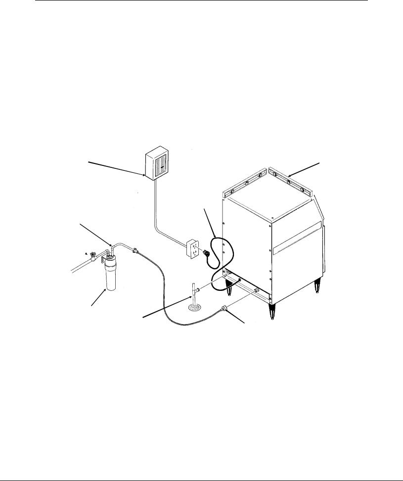
FOR THE PLUMBER
Water supply and drain connections.
1.The recommended water supply line is a 1/4" o.d. copper tube, the water pressure must have a minimum incoming pressure of 20 psig.
2.Connect the tubing to the 3/4" hose coupling thread water inlet fitting at the back of the ice maker. An optional adapter to go from the 3/4" hose coupling thread to 1/4" compression fitting is available from your dealer under part number 0533238.
Or a similar adapter can be purchased from a hardware store.
3.Install a shut off valve in the incoming water line near the ice maker so that the water can be shut off for service.
4.Connect a gravity drain line to the drain connection at the ice maker. A minimum slope of 1/4" fall per foot of horizontal run is recommended. Install the drains per the local codes.
A vent is recommended on the highest point of the drain tube, and the drain tubing must be rigid pipe. Do NOT use flexible tubing.
POWER
SUPPLY
POWER
CORD
WATER
SUPPLY
SHUT
OFF 
WATER FILTER |
|
(FIELD SUPPLIED) |
DRAIN |
ELECTRICAL
1. Locate the nameplate on the lower rear panel and check that the location source voltage and capacity are correct for this unit. The unit is equipped with a grounded plug connection.
Under no circumstances must the ground post be altered or removed.
Extension cords are not permitted.
LEVEL THE
UNIT
ADAPTER
(FIELD SUPPLIED)
Be certain that the ice maker is connected to its own electrical circuit and is individually fused. The maximum allowable voltage variation should not exceed ten percent of the nameplate rating.
All external wiring should conform to the National, State, and local electrical code requirements. Usually an electrical permit and the services of a licensed electrician will be required to install the receptacle.
January 1995
Page 4

CS60
INSTALLATION
FINAL CHECK
1.Is the Cabinet level?
2.Have all the electrical and piping connections been made?
3.Has the voltage been tested and checked against the nameplate rating?
4.Is the unit plugged into a separate electrical circuit?
5.Is the water supply line shut off valve installed and is the water turned on?
POWER?
6.Have the bin interior, and the cabinet exterior been wiped clean?
7.Are all internal parts in place, including the spray platform and curtain?
8.Have the internal refrigerant lines been checked for rubbing and chaffing?
9.Has the machine been installed where it is indoors, in a controlled environment, with adequate air circulation around the machine, and where it can be serviced?
LEVEL?
DRAINS?
WATER?
January 1995
Page 5

CS60
INITIAL START UP
1.Open water supply valve.
2.Move electrical breaker or switch to the on position.
3.Remove front panel.
4.Check the cube size control shaft, it should be in a preset cube size position. If not, turn it clockwise until the unit comes on. Note: cube size adjustments may be required. Start with the shaft in the "mid" position.
5.The machine will go thru a "dry" cycle, this will take about 10 minutes. Then the water fill and harvest cycle will begin.
6.Observe the water fill cycle:
∙The water inlet valve opens.
∙Incoming water flows from the valve through the tubing to the top of the ice maker.
∙Water flows around the inverted ice cube cups and drains through holes into the reservoir.
∙The reservoir begins to fill up with water.
∙Water continues to enter the machine and overflows a standpipe in the reservoir and down the drain.
This will take about 3 1¤2 minutes. After that the freeze cycle will begin.
7. Check the operation of the freezing cycle:
∙Compressor is running.
∙Water pump is spraying water through the spray nozzles.
∙Ice making begins, the water gets very cold, and ice begins to form in the cube molds.
8.Check that the plastic curtain assembly hangs down evenly in the opening and that no large streams of water are passing through.
Note: Some water will drip from the reservoir as the machine runs. This is normal.
9. After about 20 minutes the machine will begin to release the ice, this is called the harvest cycle.
Observe the first cube harvest:
∙Check the size of the ice cubes.
Note: The normal size of the ice cube has a 1/4" depression in the wide end.
If the cubes are not filled out, adjust the machine to make larger ice cubes by turning the cube size control shaft clockwise.
If the cubes are overfilled, adjust the machine to make smaller ice cubes by turning the cube size control counter-clockwise.
In both cases, the next cycle of cubes harvested must be observed, and further corrections may be needed.
If the ice cubes are cloudy, an extreme water condition may exist. Confirm that they are cloudy by placing them in a glass of cold water. If, in the water, they remain cloudy, you may want to have the water tested by a water treatment specialist.
If the ice cubes are cloudy only on the bottom or in the center, the machine may be running out of water before the end of the freezing cycle.
10.Test the bin full shut off. To test this, hold some ice on the bin thermostat bracket (the stainless steel tube on the left side of the ice storage bin). The ice maker should stop within a few minutes of having ice on that tube.
11.Fill out the Warranty Registration and Customer Evaluation form, and mail both to Scotsman.
12.Make sure the user understands the operation and maintenance requirements for the ice maker. Leave the service manual and the name of the local Scotsman service agency with the user.
January 1995
Page 6
 Loading...