

Schwinn A.C. Classic,A.C. Sport,A.C. Performance Service Manual
Schwinn A.C.™ Classic, Schwinn A.C.™ Sport,
and Schwinn A.C.™ Performance
Nautilus® Bowflex® Schwinn® Fitness StairMaster® Universal® Nautilus Institute
003-3331-051409A
®

© 2009 Nautilus, Inc., All rights reserved
™ and ® indicate a trademark or registered trademark. Nautilus, Inc. trademarks include NAUTILUS®, BOWFLEX®, STAIRMASTER®, SCHWINN® and UNIVERSAL® and respective logos.
1-800-NAUTILUS www.nautilus.com.. Other trademarks are the property of their respective owners.
Table of Contents
Important Safety Warnings..........................................................................................................................................................................3
Tools.................................................................................................................................................................................................................4
Serial Number.................................................................................................................................................................................................5
Troubleshooting.............................................................................................................................................................................................5
Console...........................................................................................................................................................................................10
Power Sensor................................................................................................................................................................................12
Speed Sensor.................................................................................................................................................................................13
Parts...............................................................................................................................................................................................................14
Contacts.........................................................................................................................................................................................................17
2

Important Safety Warnings
This icon means a potentially hazardous situation which, if not avoided, could result in death or serious injury. Failure to
follow these precautions can cause damage to the Schwinn® IC Bike series, serious injury to users and bystanders, and can
also compromise the effectiveness of your exercise program.
Before using this equipment, obey the following warnings:
Read and understand the Service Manual before working on the machine.
Failure to obey the instructions and safety warnings could cause injury to the service technician or bystanders.
Damaged machines or machines under repair must be marked as “Out of Service”, set aside and prevented from being 1.
used by customers.
Keep bystanders and children away from the product being serviced at all times.2.
Make sure that the repair is done in an appropriate work space away from foot traffic and exposure to bystanders. 3.
The adjustments and repairs to Nautilus equipment must only be done by a professional service technician trained to 4.
service Nautilus equipment.
Some components of the equipment can be heavy or awkward. Enlist the service of a second person when you do mainte-5.
nance steps involving these components. Do not try to do heavy or awkward steps on your own.
Use only genuine Nautilus replacement parts and hardware. Failure to use genuine replacement parts can adversely ef-6.
fect the safety and functionality of the equipment creating a risk to users.
Be sure that all warning stickers and instructional placards applied to the product stay present and in good condition 7.
when doing maintenance or replacing components. If necessary request replacement warning stickers or placards from
3

Too ls
We recommend the following tools and lubes to properly assemble, maintain and repair all Schwinn® Indoor Cycling bikes.
Tools
Torque wrench w/ 8mm Hex key socket: used to tighten the 1.
crank bolts of crank arms to the specified torque.
Pedal wrench: Has 15mm and 9/16” wrench to tighten and loosen 2.
pedals. 6mm hex key can be used on pedals with cage and toe
strap that come on the classic bike, but not on the pedals with spd
clips.
ISIS Crank puller: needed to take off right and left crank arms.3.
Bottom Bracket tool for removal and installation of ISIS BB. ISIS BB 4.
should be tightened to 600-700 kgf*cm / 44-51 lbs*ft / 60-69Nm on
both right and left sides.
Adjustable wrench: used to tighten or loosen the pop pin 5.
assembly from frame.
17mm wrench: used to adjust the inside axle nuts closest to the 6.
flywheel bearings.
15mm wrench: used to loosen the outside axle nut on each side 7.
of the flywheel bearings.
14mm wrench: used to tighten the nuts of the seat bracket.8.
Lubricants
Note: To obtain the recommended lubricates contact Nautilus
Inc. at 1-800-NAUTILUS.
Schwinn1.
®
Fit-Tech Silicone Spray: recommended for all
moving parts (e.g., handle bar post, seat post & slide, poppins, resistance knob etc.)
Schwinn2.
®
Equipment Polish: recommended on a damp cloth
when wiping down the frame after use.
Schwinn3.
®
Citrus Chain Wax: recommend to lubricate
the chain through the rear hole in the chain guard as the
flywheel is rotating.
Schwinn® Quick Shot: recommended for the threads of 4.
stabilizer bolts and pedals before tightening to crank arms.
5mm hex key and 13mm wrench used to tighten bolts on 9.
stabilizer.
The pivot bolt for the brake will use an 8mm hex wrench and a 10.
17mm wrench.
2.5 mm Hex key: used to adjust chain tensioner bolts during 11.
chain tightening, transport wheel nut and bolt and front nut of
the resistance assembly when centering brake pads.
13mm wrench for resistance knob nylon nut.12.
3mm Hex key: used for the screws of the water bottle cages.13.
Smart Release™ adjusting tool: high quality tool specifically 14.
designed for use with the new adjustable Smart Release™
mechanism. (SR Models only).
3mm Hex key: Install and remove the Console bracket and/15.
or Speed Sensor. Also attach the console bracket to the
handlebars. #2 philips screwdriver is required to remove
Console battery cover install/remove the console to the
bracket and power sensor to the brake mechanism.
2.5mm Hex key to install/service the Power Sensor.16.
4mm Hex key: All plastic hardware.17.
4
Serial Number
Serial Number
Find the serial number on the underside of the machine base. Decode the information in the serial number with the below instructions:
XXXXXX - SKU
VVV - NLS Vendor Code
WKYY - Week/Year
9999 - Machine that made production run
Troubleshooting
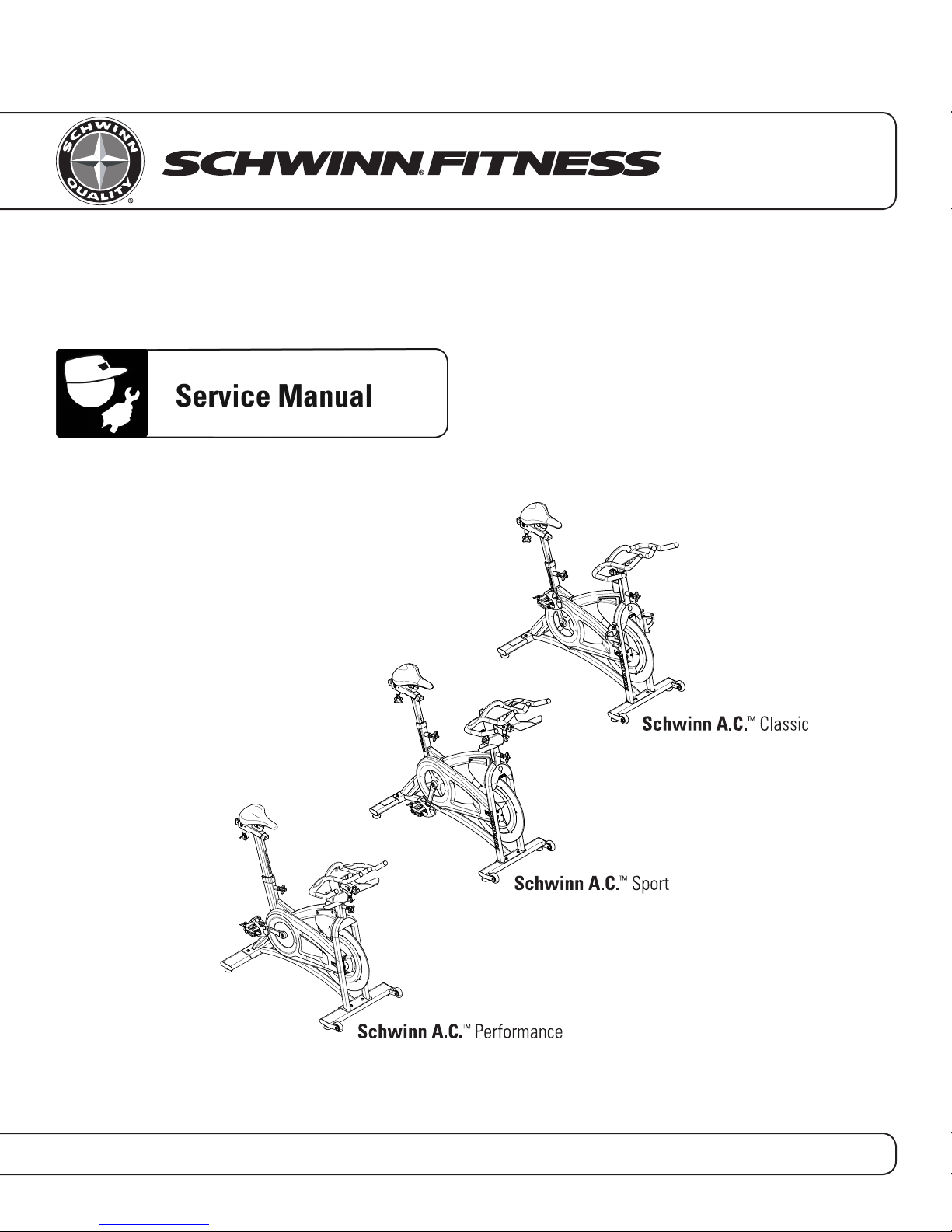
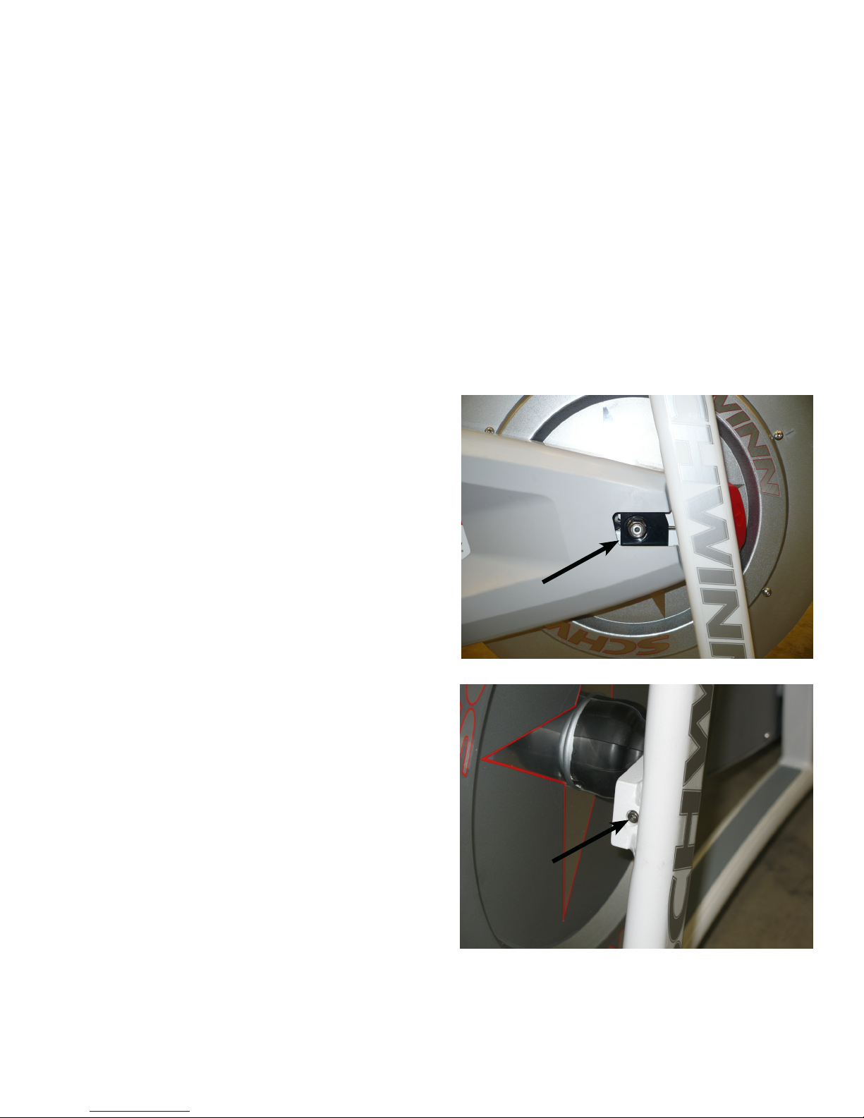
Problem: Chain is too loose, tight, or making a grinding sound.
Solution:
Use a 15mm wrench or socket to loosen flywheel nuts (A) and 1.
tensioning screws so that when you grab a pedal and try and
move it back and forth, you can feel play in the chain.
Use a 3mm Hex wrench to gradually tighten the drive side ten-2.
sioning screw (B) until you cannot feel any free play.
Check for free play with the crank in the 12, 3, 6, and 9 o’clock 3.
positions in case there is a loose or tight spot and make sure
there is no play.
Add an additional 1/2 turn on the drive side tensioning screw. 4.
This should help keep the chain tensioned as it is new and
breaks in.
Tighten the non-drive side tensioning screw to align and center 5.
the flywheel in the brake assembly.
Tighten both flywheel nuts.6.
NOTE: Make sure that the flywheel aligns with the frame.
A
B
5
Troubleshooting
Problem: Smart Release engages/disengages when pedaling
Solution: Adjust Smart Release
Attention: Only a mechanic trained to work on Schwinn® IC
bicycles should do this procedure. Make adjustments
to the Smart Release™ mechanism only to restore
the mechanism to factory specifications. Never
overtighten.
1. Begin by riding the bike. This forces the the Smart Release™
mechanism to break free. Pedal up to a moderate speed with
little or no resistance on the flywheel while applying enough
back pressure to the cranks to release the mechanism. Repeat
this several times to ensure that the mechanism is up to
operating temperature and to feel the initial setting.
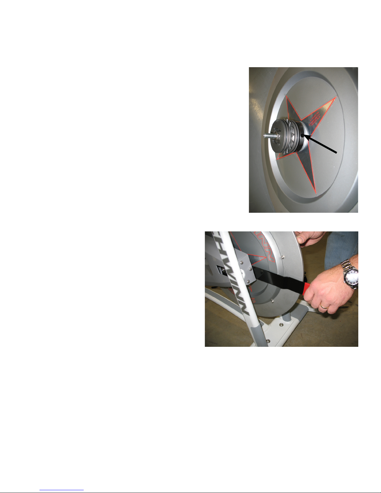
2. From the front of the bike, insert the Smart Release™ adjusting
tool into the space between the chain guard and the flywheel.
3. Rotate the flywheel until the 7mm diameter hole in the Smart
Release™ adjusting plate is visible from the front of the bike.
4. Tighten the resistance mechanism to prevent the flywheel
from rotating.
5. Place a 50 lb. dumbell or weight on the right side pedal (chain
guard side) with the crank in the 9 o’clock position.
Note: When properly adjusted, the Smart Release™
mechanism should break free allowing the crank arm
to rotate down under this amount of weight.
6. Insert the Smart Release™ Adjusting Tool so that the bend in
the tool corresponds to the shape of the flywheel.
7. Insert the pin of the tool into the hole of the Smart Release™
adjusting plate.
8. Pull the handle of the tool UP toward the top of the flywheel
to increase the release pressure (higher breakaway force)
and DOWN to decrease the release pressure (lower
breakaway force).
9. Ride the bike to test that the factory specified resistance has
been achieved.
6
 Loading...