

Page 1
BASIC MULTI-FUNCTION METERING FUNCTIONS AND CHARACTERISTICS
PM5350 series
Technical Datasheet
The PowerLogic PM5350 series power meters are the new benchmark in affordable, precision metering.
The PowerLogic PM5350, PM5350IB, PM5350PB, and PM5350P power meters offer all the measurement capabilities required
to monitor an electrical installation in a space-efficient, single 96 x 96 mm unit with small depth. DNC certifies for marine
applications.
Applications
• Panel instrumentation.
• Cost allocation or energy management
• Electrical installation remote monitoring
• Sophisticated alarming
• Circuit beaker monitoring and control
PB117510
Version: 1.0 - 05/03/2021
Version: 1.0 - 05/03/2021
PLSED310026EN
PLSED310026EN
METSEPM5350P
1
Page 2

BASIC MULTI-FUNCTION METERING FUNCTIONS AND CHARACTERISTICS
The solution for
Markets that can benefit from a solution that includes PowerLogic
PM5350 series meters:
• Buildings
• Industry
• Healthcare
• Data Centre and networks
• Infrastructure
Benefits
System integrators’ benefit
• Ease of integration
• Ease of setup
• Cost effectiveness
Panel builders’ benefit
• Ease of installation
• Cost effectiveness
• Aesthetically pleasing
• Simplified ordering
Power management solutions
Schneider Electric provides innovative
power management solutions to increase
your energy efficiency and cost savings,
maximise electrical network reliability and
availability, and optimise electrical asset
performance.
Conformity of standards
• IEC 62053-22
• IEC 61557-12
• IEC 62053-23
• IEC/UL 61010-1
• IEC 61326-1
• UL 61010-1
• IEC 61000-3-3
• FCC part 15 Class A
• DNV GL certified
End users’ benefit
• Ease of use
• Precision metering & sub-billing
• Billing flexibility
• Comprehensive, consistent and superior performance
Competitive advantages
• Easy to install and operate
• Easy for circuit breaker monitoring and control
• Power quality analysis
• Load management combined with alarm and timestamping
• High performance and accuracy
• Multi-tariff capabilities
• Individual harmonics up to 31st
2
Version: 1.0 - 05/03/2021
PLSED310026EN
Page 3
BASIC MULTI-FUNCTION METERING FUNCTIONS AND CHARACTERISTICS
PM5350 series
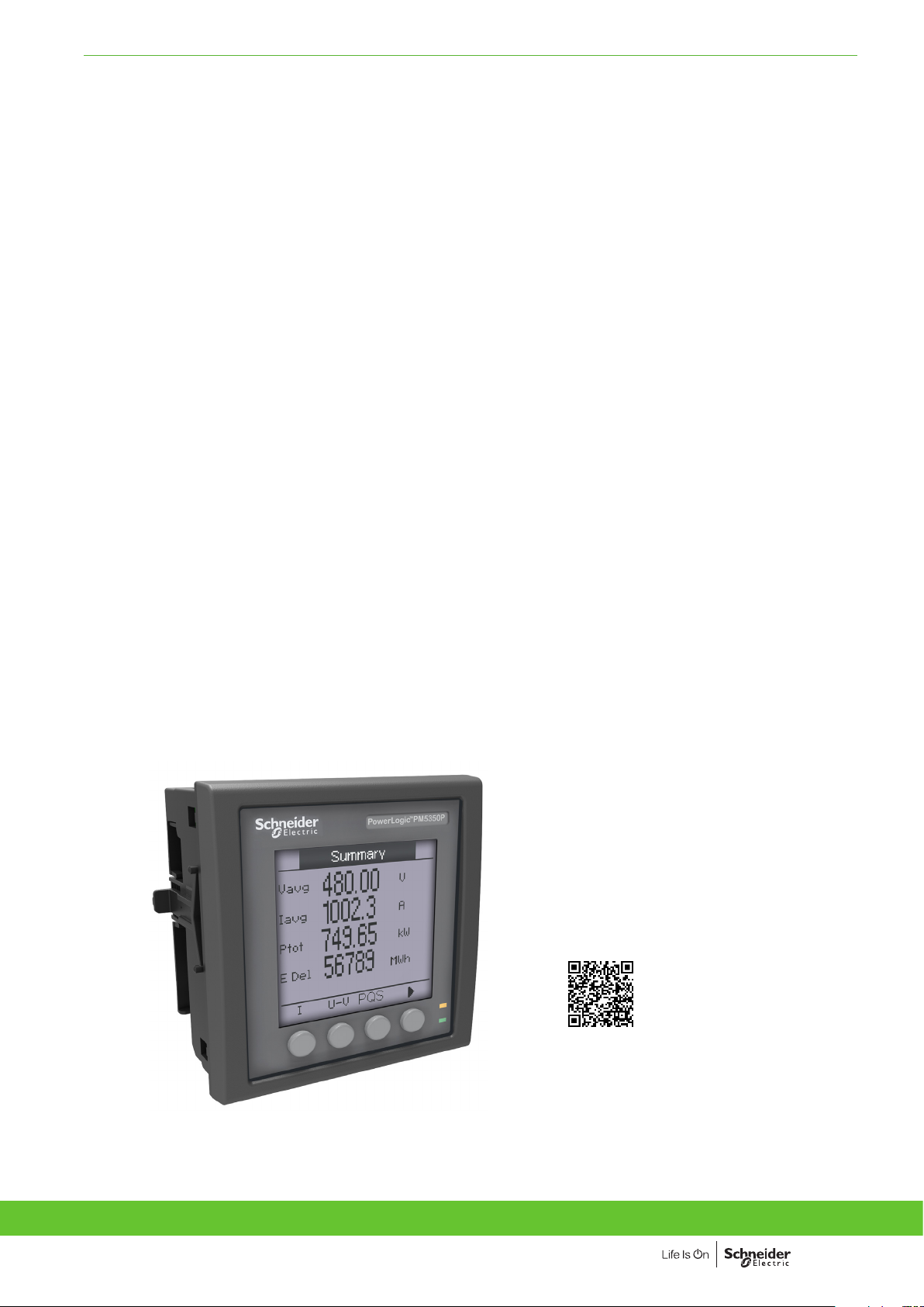
The PowerLogic PM5350 series power meter soffer electrical installation measurement
capabilities in a single 96 x 96 mm unit. Three-phases and neutral can be monitored
PB117511PB117512
simultaneously using a bright, anti-glare display with large characters and backlighting.
Menus are intuitive and the meter supports English, Chinese, Hebrew, and Spanish
languages. Its compact size and high performance make the PowerLogic PM5350
sereis suitable for many applications.
• Applications
– Panel instrumentation.
– Cost allocation or energy management.
– Electrical installation remote monitoring.
– Alarming with under/over, digital status, control power interruption, meter
reset, self diagnostic issue.
– Circuit Breaker monitoring and control with relay outputs and whetted digital
inputs.
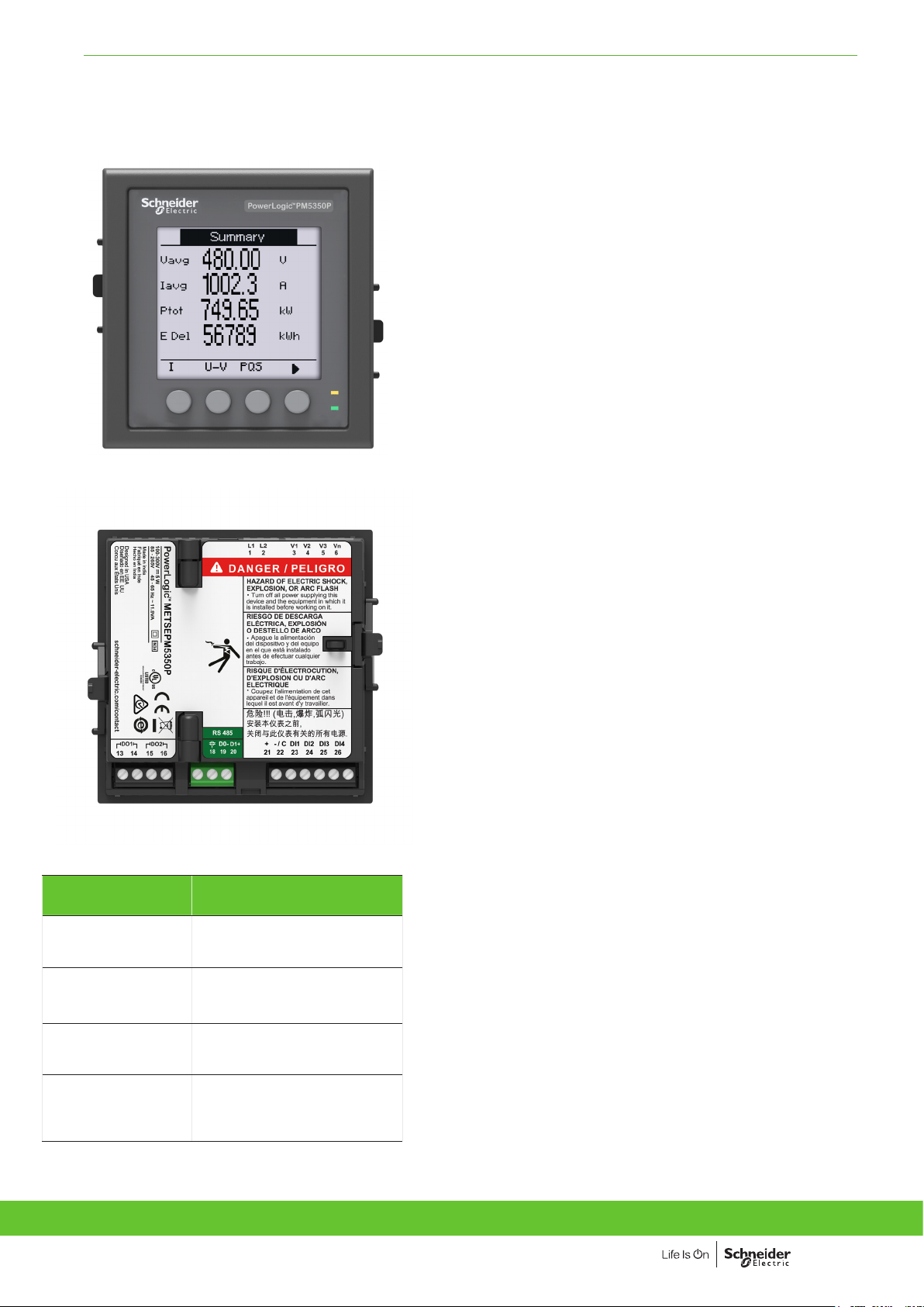
Front display of PowerLogic PM5350P front display
Rear view of PowerLogic PM5350P
Commercial
reference number
METSEPM5350
METSEPM5350IB
METSEPM5350PB
METSEPM5350P
Description
RS-485 Modbus, THD, 4DI,
2Relay
RS-485, 4DI/2Relay, Multi-level
alarm, UL480V, 4DI/2Relay
RS-485, 4DI/2Relay, Multi-level
alarm, UL300V, 4DI/2Relay
RS-485 Modbus, THD, 31st
Individual harmonics, Multitariff, 4DI/2Relay
• Main characteristics
– Easy to install
– Mounts using two clips, no tools required. Ultra compact meter
with 44 mm depth connectable up to 480 V L-L without voltage
transformers for installations compliant with category III, as per
IEC 61010-1. See specification table for UL voltage limits.
– Easy to operate
– Intuitive navigation with self-guided, language selectable menus, six
lines, four concurrent values. Two LEDs help confirm normal operation.
– Easy circuit breaker monitoring and control
– Two relay outputs (high performance) to command most circuit
breaker coils directly. Monitored switches can be wired directly without
external power supply.
– System status at a glance
– Bright, anti-glare, backlit display plus two LEDs; orange for energy
pulse or alarm and green for heartbeat/communications indication.
– IEC 62053-22 class 0.5S accuracy for active energy
– Accurate energy measurement for cost allocation.
– Power Quality analysis
– The PM5350P offers THD and TDD measurements as standard. Total
Demand Distortion is based on a point of common coupling (PCC),
which is a common point that each user receives power from the
power source. The TDD compares the contribution of harmonics
versus the maximum demand load. In addition, it has individual
harmonics (odd) measurement up to 31st harmonics. These types of
power quality parameters help to identify the source of harmonics that
can harm transformers, capacitors, generators, motors and electronic
equipment.
• Load management
– Peak demands with Timestamping are provided. Predicted demand
values can be used in basic load shedding applications.
Alarming with timestamping
– Over 30 alarm conditions, such as under/over conditions, digital input
changes, and phase unbalance inform you of events. A time-stamped
log maintains a record of the last 40 alarm events.
– Load timer setpoint adjustable to monitor and advise maintenance
requirements.
– Performance Standard Meets IEC 61557-12 PMD/Sx/K70/0.5.
Version: 1.0 - 05/03/2021
Version: 1.0 - 05/03/2021
PLSED310026EN
PLSED310026EN
3
Page 4

BASIC MULTI-FUNCTION METERING FUNCTIONS AND CHARACTERISTICS
PM5350 series
Feature guide
General
Use on LV and MV systems
Basic metering with THD and min/max readings
Instantaneous rms values
Current Total, Phases and neutral
Voltage Total, Ph-Ph and Ph-N
Frequency
Real, reactive, and
apparent power
True Power Factor Total and per phase
Displacement PF Total and per phase
Unbalanced I, VL-N, VL-L
Accumulated Active, Reactive and Apparent Energy
Stored in non-volatile memory
Demand values
Current average Present, Last, Predicted,
Active power Present, Last, Predicted,
Reactive power Present, Last, Predicted,
Apparent power Present, Last, Predicted,
Multi-tariff
Peak demand with timestamping D/T for current &
powers
Demand calculation Sliding, fixed and rolling
Synchronization of the measurement window
Other measurements
I/O timer
Operating timer
Active load timer
Alarm counters
Power quality measurements
THD, thd (Total Harmonic Distortion)
TDD, thd (Total Demand Distortion)
Harmonics Individual (Odd)
Data recording
Min/max of instantaneous values, plus phase
identification
Alarms with 1s timestamping
Alarms stored in non-volatile memory
Inputs/Outputs
Digital inputs
Digital outputs
Display
White backlit LCD display, 6 lines, 4 concurrent values
IEC or IEEE visualization mode
Communication
Modbus RTU, Modbus ASCII, Jbus Protocol
Firmware update via RS-485 serial port
(DLF3000 via the Schneider Electric website:
www.se.com)
Total and per phase
Peak, & Peak Date Time
Peak, & Peak Date Time
Peak, & Peak Date Time
Peak, & Peak Date Time
block, thermal
PM5350P PM5350 PM5350IB PM5350PB
b
b
b
b
b
Signed
Signed, Four Quadrant
Signed, Four Quadrant
b
Received/Delivered;
Net and absolute;
b
b
b
b
16 tariffs
b
b
b
b
b
b
b
I, V L-N, V L-L
b
31st
b
Standard 29; Unary 4; Digital 4
40 events
4 (DI1, DI2, DI3, DI4)
2 relay outputs
(DO1, DO2)
b
b
b
b
4
Version: 1.0 - 05/03/2021
PLSED310026EN
Page 5

BASIC MULTI-FUNCTION METERING FUNCTIONS AND CHARACTERISTICS
PM5350 series
Electrical characteristics
Type of measurement
Measurement
accuracy
Data update rate 1 second nominal (50/60 cycles)
Input-voltage VT primar y
Input-current
AC control
power
DC control
power
Real time clock Battery backup 30 seconds ride-through
Digital output Number/Type 2 - Mechanical Relays
Status Digital
Inputs
Whetting output Nominal voltage 24 V DC
Current, Phase
Voltage, L-N
Power Factor
Power, Phase
Frequency
Real Energy
Reactive Energy
U
nom
Measured voltage with
overrange & Crest
Factor
Permanent overload 700 V AC L-L, 404 V AC L-N
Impedance 10 MW
Burden 0.2 VA at 240 V AC L-N
Frequency range 45 to 70 Hz
CT ratings Secondary 1 A, 5 A nominal
Measured voltage with
overrange & crest factor
Withstand
Impedance < 0.3 mW
Frequency range 45 to 70 Hz
Burden < 0.024 VA at 9 A
Operating range 85 - 265 V AC
Burden At 120 V AC, 4.1 VA/ 1.5 W typical
Frequency 45 to 65 Hz
Ride-through time Typical at 120 V AC and with maximum burden
Operating range 100 to 300 V DC
Burden Typical/ Maximum at 125 V DC
Ride-through time Typical at 125 V DC and with maximum burden 50 mS 30 mS 50 mS
Output frequency 0.5 Hz maximum
Switching Current 30 V DC, 5 A
Isolation 2.5 kVrms
Voltage ratings ON 18.5 to 36 V DC,
Input Resistance 110 k W
Maximum Frequency 2 Hz (T ON min = T OFF min = 250 ms)
Response Time 10 ms
Isolation 2.5 kVrms
Allowable load 4 mA
Isolation 2.5 kVrms
(1)
(1)
(2)
(1)
(3)
True rms measurement in 1P, 2P, 3P network,
supports 13 wiring schemes.
32 samples per cycle, zero blind
(1)
±0.30 %
±0.30 %
±0.005
IEC 61557-12 Class 0.5; For 5 A nominal CT
±0.05 %
IEC 62053-22 Class 0.5S
IEC 61557-12 Class 0.5
(4)
IEC 62053-23 Class 2
IEC 61557-12 Class 2
1.0 MV AC max, starting voltage depends on VT ratio
277 V L-N
IEC: 20 to 480 V AC L-L; 20 to 277 V AC L-N, CAT III
IEC: 20 to 690 V AC L-L; 20 to 400 V AC L-N, CAT II
UL: 20 to 300 V AC L-L, CAT III
5 mA to 9 A
Continuous 20 A,10 sec/hr 50 A,1 sec/hr 500 A
At 230 V AC, 6.3 VA/ 2.0 W typical
At 265 V AC, 9.6 VA/ 3.5 W typical
Typical at 230 V AC and with maximum burden
Typical/ Maximum at 250 V DC
Typical Maximum at 300 V DC
(1 second ON / 1 second OFF - minimum times)
250 V AC, 8 A Cos φ = 1
250 V AC, 6 A Cos φ = 0.4
OFF 0 to 4 V DC
PM5350 PM5350P PM5350PB/IB
b
0.2% (Avg A)
b
0.2% (Avg A)
b
st
31
b
b
b
b
b
b
b
b
b
b and
UL: 20 to 480 V AC L-L
b
b
b
45 to 65 Hz
b
b
b
b
b
b
b
b
6.7 VA / 2.7 W
8.6 VA / 2.9 W
11.9 VA / 3.5 W
7 VA / 4 W
9 VA / 5 W
11.9 VA / 5 W
6.7 VA / 2.7 W
8.6 VA / 2.9 W
11.9 VA / 3.5 W
b
100 mS
400 mS
40 mS
250 mS
100 mS
400 mS
b
1.4 W / 2.6 W
1.8 W / 2.7 W
3.8 W max
b
4 W max
5 W max
5 W max
3 years backup
without control power
1.4 W / 2.6 W
1.8 W / 2.7 W
3.8 W max
b
b
b
b
b
b
b
b
b
b
b
b
b
b
b
b
b
(1) Measurements taken from 45 Hz to 65 Hz, 0.5 A to 9 A, 57 V to 347 V & 0.5 ind to 0.5 cap power factor with a sinusoidal wave.
(2) Active power: ±0.5 % from 0.25 A to 9.0 A at Cos φ = 1, ±0.6 % from 0.50 A to 9.0 A at Cos φ = 0.5 (ind or cap)
(3) Real/active Energy: ±0.5 % from 0.25 A to 9.0 A at Cos φ = 1, ±0.6 % from 0.50 A to 9.0 A at Cos φ = 0.5 (ind or cap) IEC 61557-12 Class 0.5
(4) Reactive energy: ±2.0 % from 0.25 A to 9.0 A at Sin φ = 1±2.5 % from 0
Version: 1.0 - 05/03/2021
Version: 1.0 - 05/03/2021
PLSED310026EN
PLSED310026EN
5
Page 6

BASIC MULTI-FUNCTION METERING DIMENSIONS AND CONNECTION
PM5350 / PM5350P series
Rear of meter - open
PE86279PE86274
Rear view retainers - installation
Rear view retainers - users
PE86275
For detailed installation instructions see the product's Installation Guide.
PB113626
PB113626
PM5350 / PM5350P meter parts
A Retainer clips.
B Control power supply connector.
C Voltage inputs.
D Digital outputs.
E RS-485 port (COM1).
F Digital input.
G Optical revenue switch.
H Current inputs.
For detailed installation instructions see the product’s Installation Guide.
6
Version: 1.0 - 05/03/2021
PLSED310026EN
Page 7

BASIC MULTI-FUNCTION METERING DIMENSIONS AND CONNECTION
PM5350IB/PB series
PB113626
Dimensions PM5350IB
PB113626
Dimensions PM5350PB
Parts of PM5350IB and PM5350PB (rear panel door removed)
PB113626
PB113626
PM5350IB
PM5350IB
A Control power
B Voltage inputs
C Current inputs
D Digital inputs
E Whetting voltage source (for digital inputs)
F RS-485 communications
G Digital outputs
H Retainer clips
PM5350PB
PM5350PB
For detailed installation instructions see the product’s Installation Guide.
Version: 1.0 - 05/03/2021
PLSED310026EN
7
Page 8

Schneider Electric Industries SAS
35, Rue Joseph Monier,
CS 30323
F - 92506 Rueil Malmaison Cedex
RCS Nanterre 954 503 439
Capital social 896 313 776
www.se.com
March 2021
PowerLogic™ PM5350 series
PLSED310026EN
As standards, specications and designs develop from time to time, please ask
for conrmation of the information given in this document.
Design: Schneider Electric
Photos: Schneider Electric
Over 75 % of Schneider Electric products
have been awarded the Green Premium ecolabel.
© 2021 – Schneider Electric - All rights reserved
 Loading...