

Page 1
Page 2

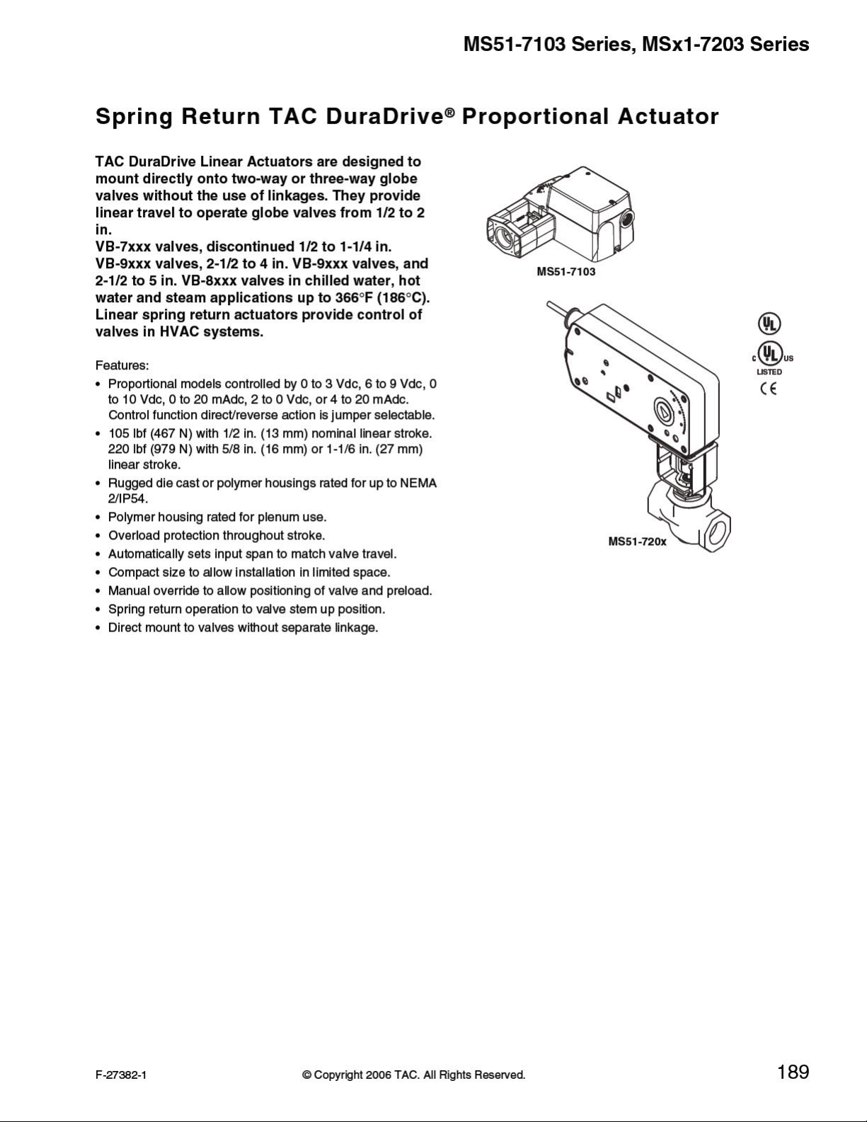
MS51-7103 Series, MSx1-7203 Series
Model Chart
Actuator Power Input
Part No.
MS51-7103-
b
000
MS51-7103-
b
100
MS51-7103-
b
020
MS51-7103-
b
120
MS51-7103-
b
030
MS51-7103-
b
130
MS51-7103-
d
040 b
MS51-7103-
b d
140
MS51-7103-
b
050
MS51-7103-
b
150
MS51-7103-
b
060
MS51-7103-
b
160
Control
Action
2 to 10 Vdc
Proportional
0 to 3 Vdc
Proportional
6 to 9 Vdc
Proportional
0 to 10 Vdc
Proportional
4 to 20 mAdc
c
24 Vac ±
Voltage
20%
20 to 30
Vdc
Running Holding
50 Hz 60 Hz
50/60 Hz
DC
VA W VA W W Powered
Amps
6.6 4.2 6.6 4.2 0.14 1.5
7.8 4.9 7.8 4.9 0.16 3.4
6.6 4.2 6.6 4.2 0.14 1.5
Linear
Stroke
Inches
1/2 in.
nominal
MS51-7203 2 to 10 Vdc
MS51-7203-
f
040
MS51-7203050
MS61-7203 2 to 10 Vdc
MS61-7203-
f
040
MS61-7203050
a
Timing was measured with no load applied to the actuator.
b
Proportional (MS) mo dels shipped with RA/DA jumper set for DA (actuator extends with increasing signal).
c
4 to 20 mAdc with AM-708 500 ohm field-installed resistor.
d
Has 20 Vdc 25 mA power supply for TAC System 8000 applications.
e
Current VB-7xxx Series valves and discontinued VB-9xxx Series valves (1-1/4 in. only).
f
20 Vdc 25 mA power supply included (replaces position feedback wires).
g
Current VB-9xxx Series valves (2-1/2 to 4 in.), current VB-8xxx (2 to 5 in.) Series valves, and discontinued VB-9xxx (1-1/2 to 2 in.) Series valves.
6-9 Vdc
0-10 Vdc
6-9 Vdc
0-10 Vdc
24 Vac ±
20%
22 to 30
Vdc
9.8 7.4 9.7 7.4 .28 2.9
1-1/16 <190 <40
Approximate Timing
in Seconds @ 70°F
60 16 105 215 1/2 to 2
5/8 <100
(21°C)
a
Spring
Return
<35
Output Force
Rating lb.-in.
(N-m)
Max.
Min.
Stall
220
(919)
495
(2202)
Valve
Size
inches
1-1/4 to
e
2
2-1/2 to
4 or 5
g
190
© Copyright 2006 TAC. All Rights Reserved. F-27382-1
Page 3

MS51-7103 Series, MSx1-7203 Series
Specifications
Inputs
Control signal See Model Chart for actuator models and control type.
Power
Connections
Outputs
Electrical
Mechanical
Environment
Ambient temperature limits
Humidity
Locations
Dimensions
Agency Listings
UL 873 Underwriters Laboratories (File #E9429 Category Temperature-Indicating and Regulating Equipment).
CUL UL Listed for use in Canada by Underwriters Laboratories. Canadian Standards C22-2 No. 24-93
European Community EMC Directive (89/336/EEC). Low Voltage Directive (72/23/EEC).
Australia
See Model Chart. All 24 Vac circuits are Class 2. All circuits 30 Vac and above are Class 1. Half wave
device.
Models with -0xx have 3 ft. (91 cm) appliance wire connections. Models with -1xx have 3 ft. (91 cm)
plenum wire connections. Enclosure accepts 1/2 in. (13 mm) conduit connectors.
For M20 Metric connector, use AM-756 adaptor.
Position Feedback Voltage: For voltage ranges, the feedback signal is the same range as the input
signal. The 4 to 20 mAdc current input range have a 2 to 10 Vdc position feedback signal. The position
feedback signal can supply up to 0.5 mAdc to operate up to four additional slave actuators. The MS517103-040 and -140, MS51-7203-040, MS61-7203-040 do not have feedback.
Linear Stroke: See Model Chart.
Approximate Stroke Timing: See Model Chart.
Manual Override: Allows positioning of valve and preload using manual crank.
Shipping and Storage: -40 to 160qF (-40 to 71qC). MS51-720x and MS61-720x: -40 to 180qF (-40 to
82qC).
Operating: -22 to 140qF (-30 to 60qC). MS51-720x and MS61-720x: 0 to 140qF (-18 to 60qC)
Temperature Restrictions: For maximum ambient 140qF (60qC) the maximum allowable fluid
temperature should not exceed valve rating. See F-27252 Selection Guide for specific ratings.
MS51-7103: 5 to 95% RH, non-condensing. MS51-7203 and MS61-7203: 15 to 95% RH, noncondensing.
NEMA 1. NEMA 2 (enclosure is air plenum rated), UL Type 2 (IEC IP54) with customer supplied water
tight conduit connections.
MS51-7103: 6-5/16 H x 6-49/64 W x 3-1/2 D in. (160 x 172 x 89 mm).
MS51-7203: 7 H x 10-5/8 W x 2-9/16 D in. (178 x 270 x 65 mm).
MS61-7203: 9-9/16 H x 10-5/8 W x 2-9/16 D in. (243 x 270 x 65 mm).
This product meets requirements to bear the C-Tick Mark according to the terms specified by the
Communications Authority under the Radio Communications Act 1992.
Accessories
Model No. Description
AM-703 Input rescaling module, adjust signals to 2 to 10 Vac, zero and span adjust.
AM-704 Interface, pulse width modulation (PWM).
AM-705 Positioner (NEMA 4 housing).
AM-706 Min and/or manual positioner for flush panel mount.
AM-708 500 ohm resistor for 4 to 20 mA control signal.
AM-756 Metric conduit adapter M20 x 1.5 to 1/2 in. NPT.
MS51-7103
AM-764 Linkage kit for damper applications.
AM-770 Replacement valve linkage parts kit.
MS51-71xx, MS51-72xx, and MS61-72xx
AM-731 Mounting kit - MS51-720x (stem extension, lock washer, jam nut, connecting pin; included with actuator).
AM-732 Mounting kit - MS61-720x (stem extension, lock washer, jam nut, connecting pin; included with actuator).
AM-733 Retrofit kit - discontinued VB-9xxx 1-1/2 to 2 in. valves after 9404 date code.
AM-734 Retrofit kit - discontinued VB-9xxx 1-1/2 to 2 in. valves prior to 9404 date code.
AM-756 Metric conduit adaptor M20 x 1.5 to 1/2 in. NPT.
AM-763 1/8 in. Hex crank for manual override.
F-27382-1 © Copyright 2006 TAC. All Rights Reserved. 191
 Loading...