

MasterPactMTZ2/MTZ3
DOCA0101EN-04 07/2020
MasterPact MTZ2/MTZ3
IEC Circuit Breakers and Switch-Disconnectors
from 800 to 6300 A
User Guide
07/2020
DOCA0101EN-04
www.schneider-electric.com

The information provided in this documentation contains general descriptions and/or technical characteristics of the performance of the products contained herein. This documentation is not intended as a
substitute for and is not to be used for determining suitability or reliability of these products for specific user
applications. It is the duty of any such user or integrator to perform the appropriate and complete risk
analysis, evaluation and testing of the products with respect to the relevant specific application or use
thereof. Neither Schneider Electric nor any of its affiliates or subsidiaries shall be responsible or liable for
misuse of the information contained herein. If you have any suggestions for improvements or amendments
or have found errors in this publication, please notify us.
You agree not to reproduce, other than for your own personal, noncommercial use, all or part of this
document on any medium whatsoever without permission of Schneider Electric, given in writing. You also
agree not to establish any hypertext links to this document or its content. Schneider Electric does not grant
any right or license for the personal and noncommercial use of the document or its content, except for a
non-exclusive license to consult it on an "as is" basis, at your own risk. All other rights are reserved.
All pertinent state, regional, and local safety regulations must be observed when installing and using this
product. For reasons of safety and to help ensure compliance with documented system data, only the
manufacturer should perform repairs to components.
When devices are used for applications with technical safety requirements, the relevant instructions must
be followed.
Failure to use Schneider Electric software or approved software with our hardware products may result in
injury, harm, or improper operating results.
Failure to observe this information can result in injury or equipment damage.
© 2020 Schneider Electric. All rights reserved.
2 DOCA0101EN-04 07/2020

Table of Contents
Safety Information. . . . . . . . . . . . . . . . . . . . . . . . . . . . . . . . . . . . . . . . . . . . 5
About the Book . . . . . . . . . . . . . . . . . . . . . . . . . . . . . . . . . . . . . . . . . . . . . . 7
Chapter 1 MasterPact MTZ2/MTZ3 Description . . . . . . . . . . . . . . . . . . . . . . . . . . . . . 9
MasterPact MTZ2/MTZ3 Range . . . . . . . . . . . . . . . . . . . . . . . . . . . . . . . . . . . . . . . . . . . . . .
Fixed Device . . . . . . . . . . . . . . . . . . . . . . . . . . . . . . . . . . . . . . . . . . . . . . . . . . . . . . . . . . . . .
Drawout Device . . . . . . . . . . . . . . . . . . . . . . . . . . . . . . . . . . . . . . . . . . . . . . . . . . . . . . . . . . .
Device Identification . . . . . . . . . . . . . . . . . . . . . . . . . . . . . . . . . . . . . . . . . . . . . . . . . . . . . . .
MicroLogic X Control Unit: Description . . . . . . . . . . . . . . . . . . . . . . . . . . . . . . . . . . . . . . . . .
Go2SE Landing Page . . . . . . . . . . . . . . . . . . . . . . . . . . . . . . . . . . . . . . . . . . . . . . . . . . . . . .
Operating Conditions. . . . . . . . . . . . . . . . . . . . . . . . . . . . . . . . . . . . . . . . . . . . . . . . . . . . . . .
Chapter 2 MasterPact MTZ2/MTZ3 Normal Operation . . . . . . . . . . . . . . . . . . . . . . . . 33
2.1 Device Operating Actions . . . . . . . . . . . . . . . . . . . . . . . . . . . . . . . . . . . . . . . . . . . . . . . . . . .
Operating the Device. . . . . . . . . . . . . . . . . . . . . . . . . . . . . . . . . . . . . . . . . . . . . . . . . . . . . . .
Control Modes . . . . . . . . . . . . . . . . . . . . . . . . . . . . . . . . . . . . . . . . . . . . . . . . . . . . . . . . . . . .
Opening the Device. . . . . . . . . . . . . . . . . . . . . . . . . . . . . . . . . . . . . . . . . . . . . . . . . . . . . . . .
Closing the Device. . . . . . . . . . . . . . . . . . . . . . . . . . . . . . . . . . . . . . . . . . . . . . . . . . . . . . . . .
Resetting the Circuit Breaker. . . . . . . . . . . . . . . . . . . . . . . . . . . . . . . . . . . . . . . . . . . . . . . . .
Engaging the ERMS Function . . . . . . . . . . . . . . . . . . . . . . . . . . . . . . . . . . . . . . . . . . . . . . . .
Operating Accessories . . . . . . . . . . . . . . . . . . . . . . . . . . . . . . . . . . . . . . . . . . . . . . . . . . . . .
2.2 Drawout Device Racking Actions . . . . . . . . . . . . . . . . . . . . . . . . . . . . . . . . . . . . . . . . . . . . .
Drawout MasterPact MTZ2/MTZ3 Device Status . . . . . . . . . . . . . . . . . . . . . . . . . . . . . . . . .
Disconnecting the Drawout Device . . . . . . . . . . . . . . . . . . . . . . . . . . . . . . . . . . . . . . . . . . . .
Connecting the Drawout Device . . . . . . . . . . . . . . . . . . . . . . . . . . . . . . . . . . . . . . . . . . . . . .
Removing the Drawout Device . . . . . . . . . . . . . . . . . . . . . . . . . . . . . . . . . . . . . . . . . . . . . . .
Installing the Drawout Device in the Chassis . . . . . . . . . . . . . . . . . . . . . . . . . . . . . . . . . . . .
2.3 Device Locking Actions . . . . . . . . . . . . . . . . . . . . . . . . . . . . . . . . . . . . . . . . . . . . . . . . . . . . .
Locking the Pushbuttons . . . . . . . . . . . . . . . . . . . . . . . . . . . . . . . . . . . . . . . . . . . . . . . . . . . .
Locking the Device in Open Position with Padlocks . . . . . . . . . . . . . . . . . . . . . . . . . . . . . . .
Locking the Device in Open Position with Keylocks . . . . . . . . . . . . . . . . . . . . . . . . . . . . . . .
Chassis Locking in Disconnected Position . . . . . . . . . . . . . . . . . . . . . . . . . . . . . . . . . . . . . .
Chassis Locking in Any Position . . . . . . . . . . . . . . . . . . . . . . . . . . . . . . . . . . . . . . . . . . . . . .
Locking the Safety Shutters. . . . . . . . . . . . . . . . . . . . . . . . . . . . . . . . . . . . . . . . . . . . . . . . . .
2.4 Device Interlocking Actions . . . . . . . . . . . . . . . . . . . . . . . . . . . . . . . . . . . . . . . . . . . . . . . . . .
Mismatch Protection . . . . . . . . . . . . . . . . . . . . . . . . . . . . . . . . . . . . . . . . . . . . . . . . . . . . . . .
VPEC Door Interlock . . . . . . . . . . . . . . . . . . . . . . . . . . . . . . . . . . . . . . . . . . . . . . . . . . . . . . .
VPOC Open-door Racking Interlock . . . . . . . . . . . . . . . . . . . . . . . . . . . . . . . . . . . . . . . . . . .
IPA Cable-type Door Interlock . . . . . . . . . . . . . . . . . . . . . . . . . . . . . . . . . . . . . . . . . . . . . . . .
Mechanical Interlocking for Transfer Switches . . . . . . . . . . . . . . . . . . . . . . . . . . . . . . . . . . .
DAE Automatic Spring-Discharge Interlock. . . . . . . . . . . . . . . . . . . . . . . . . . . . . . . . . . . . . .
IBPO Racking Interlock Between Racking Handle and Opening Pushbutton . . . . . . . . . . . .
Chapter 3 MasterPact MTZ Critical Cases . . . . . . . . . . . . . . . . . . . . . . . . . . . . . . . . . 107
Finding the Cause of a Trip or an Alarm in Critical Cases. . . . . . . . . . . . . . . . . . . . . . . . . . .
Resetting the Circuit Breaker After a Trip Due to an Electrical Fault . . . . . . . . . . . . . . . . . .
Resetting the Circuit Breaker After a Trip Due to an Incident Detected by the MicroLogic X
Self-tests . . . . . . . . . . . . . . . . . . . . . . . . . . . . . . . . . . . . . . . . . . . . . . . . . . . . . . . . . . . . . . . .
Diagnosing Alarms . . . . . . . . . . . . . . . . . . . . . . . . . . . . . . . . . . . . . . . . . . . . . . . . . . . . . . . .
Diagnosing Error Messages . . . . . . . . . . . . . . . . . . . . . . . . . . . . . . . . . . . . . . . . . . . . . . . . .
10
12
16
23
26
29
31
34
35
39
44
47
50
51
53
60
61
65
68
71
74
77
78
80
82
84
88
90
93
94
96
99
102
103
105
105
108
111
114
116
124
DOCA0101EN-04 07/2020 3

Chapter 4 MasterPact MTZ Commissioning . . . . . . . . . . . . . . . . . . . . . . . . . . . . . . . . . 127
Introduction to Commissioning. . . . . . . . . . . . . . . . . . . . . . . . . . . . . . . . . . . . . . . . . . . . . . . .
Inspection and MicroLogic X Settings . . . . . . . . . . . . . . . . . . . . . . . . . . . . . . . . . . . . . . . . . .
Tests . . . . . . . . . . . . . . . . . . . . . . . . . . . . . . . . . . . . . . . . . . . . . . . . . . . . . . . . . . . . . . . . . . .
Communication Tests . . . . . . . . . . . . . . . . . . . . . . . . . . . . . . . . . . . . . . . . . . . . . . . . . . . . . .
Final Checks and Reporting. . . . . . . . . . . . . . . . . . . . . . . . . . . . . . . . . . . . . . . . . . . . . . . . . .
MasterPact MTZ Test Form . . . . . . . . . . . . . . . . . . . . . . . . . . . . . . . . . . . . . . . . . . . . . . . . . .
128
130
132
135
136
137
Chapter 5 MasterPact MTZ Troubleshooting . . . . . . . . . . . . . . . . . . . . . . . . . . . . . . . . 141
Introduction to Troubleshooting . . . . . . . . . . . . . . . . . . . . . . . . . . . . . . . . . . . . . . . . . . . . . . .
Troubleshooting: Chassis Operation . . . . . . . . . . . . . . . . . . . . . . . . . . . . . . . . . . . . . . . . . . .
Troubleshooting: Unexpected Tripping . . . . . . . . . . . . . . . . . . . . . . . . . . . . . . . . . . . . . . . . .
Troubleshooting: Mechanical Control Operations . . . . . . . . . . . . . . . . . . . . . . . . . . . . . . . . .
Troubleshooting: Electrical Control Operations . . . . . . . . . . . . . . . . . . . . . . . . . . . . . . . . . . .
Troubleshooting: Control Operations from EcoStruxure Power Device App . . . . . . . . . . . . .
Troubleshooting: Control Operations from IO Module . . . . . . . . . . . . . . . . . . . . . . . . . . . . . .
Troubleshooting: Control Operations from EcoStruxure Power Commission Software . . . . .
Troubleshooting: Control Operations from IFE/EIFE Webpages . . . . . . . . . . . . . . . . . . . . . .
Troubleshooting: Control Operations from Communication Network. . . . . . . . . . . . . . . . . . .
Troubleshooting: Control Operations from FDM128 Display . . . . . . . . . . . . . . . . . . . . . . . . .
142
144
145
146
147
149
151
152
154
156
158
Chapter 6 Schneider Electric Green Premium™ Ecolabel . . . . . . . . . . . . . . . . . . . . . . 159
Schneider Electric Green Premium™ Ecolabel . . . . . . . . . . . . . . . . . . . . . . . . . . . . . . . . . . .
159
4 DOCA0101EN-04 07/2020
Safety Information
Important Information
NOTICE
Read these instructions carefully, and look at the equipment to become familiar with the device before
trying to install, operate, service, or maintain it. The following special messages may appear throughout
this documentation or on the equipment to warn of potential hazards or to call attention to information that
clarifies or simplifies a procedure.
PLEASE NOTE
Electrical equipment should be installed, operated, serviced, and maintained only by qualified personnel.
No responsibility is assumed by Schneider Electric for any consequences arising out of the use of this
material.
A qualified person is one who has skills and knowledge related to the construction and operation of
electrical equipment and its installation, and has received safety training to recognize and avoid the
hazards involved.
DOCA0101EN-04 07/2020 5
SAFETY NOTICE
HAZARD OF ELECTRIC SHOCK, EXPLOSION, OR ARC FLASH
Apply appropriate personal protective equipment (PPE) and follow safe electrical work practices. See
NFPA 70E, CSA Z462, NOM 029-STPS or local equivalent.
This equipment must only be installed and serviced by qualified electrical personnel.
Turn off all power supplying this equipment before working on or inside this equipment.
Always use a properly rated voltage sensing device to confirm power is off.
Replace all devices, doors, and covers before turning on power to this equipment.
Beware of potential hazards, and carefully inspect the work area for tools and objects that may have
been left inside the equipment.
Failure to follow these instructions will result in death or serious injury.
CYBERSECURITY SAFETY NOTICE
POTENTIAL COMPROMISE OF SYSTEM AVAILABILITY, INTEGRITY, AND CONFIDENTIALITY
Change default passwords at first use to help prevent unauthorized access to device settings,
controls, and information.
Disable unused ports/services and default accounts to help minimize pathways for malicious
attackers.
Place networked devices behind multiple layers of cyber defenses (such as firewalls, network
segmentation, and network intrusion detection and protection).
Use cybersecurity best practices (for example, least privilege, separation of duties) to help prevent
unauthorized exposure, loss, modification of data and logs, or interruption of services.
Failure to follow these instructions can result in death, serious injury, or equipment damage.
DANGER
WARNING
6 DOCA0101EN-04 07/2020
At a Glance
Document Scope
Validity Note
Online Information
About the Book
The aim of this guide is to provide users, installers, and maintenance personnel with technical information
needed to operate MasterPact™ MTZ2/MTZ3 circuit breakers and switch-disconnectors, in compliance
with the IEC standards.
This guide applies to MasterPact MTZ2/MTZ3 circuit breakers and switch-disconnectors.
This guide applies to MicroLogic™ X control units:
With firmware version 004.000.000 or greater
With hardware version 001.000.000 or greater
NOTE: This guide also applies to MicroLogic™ Xi control units. A MicroLogic Xi control unit is a
MicroLogic X control unit without Bluetooth low energy (BLE) communication.
The specific features of the MicroLogic Xi control units are described in the appendix in
MasterPact MTZ - MicroLogic X Control Unit - User Guide
.
DOCA0102EN
The information contained in this guide is likely to be updated at any time. Schneider Electric strongly
recommends that you have the most recent and up-to-date version available on
www.se.com/ww/en/download
.
The technical characteristics of the devices described in this guide also appear online. To access the
information online, go to the Schneider Electric home page at
www.se.com
.
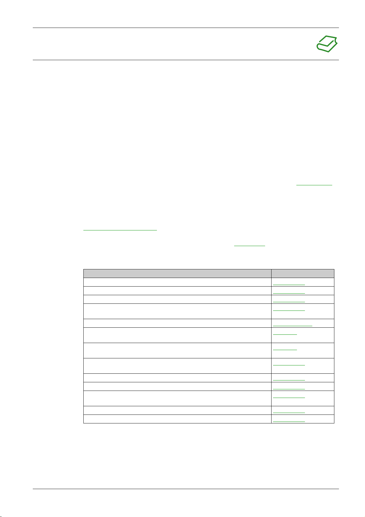
Related Documents
Title of Documentation Reference Number
MasterPact MTZ - MicroLogic X Control Unit - User Guide DOCA0102EN
MasterPact MTZ - Modbus Communication Guide DOCA0105EN
MasterPact MTZ - IEC 61850 Communication Guide DOCA0162EN
MasterPact MTZ - IEC Circuit Breakers and Switch-Disconnectors - Maintenance
Guide
MasterPact MTZ Catalogue LVPED216026EN
MasterPact MTZ2/MTZ3 - Fixed IEC Circuit Breaker or Switch-Disconnector Instruction Sheet
MasterPact MTZ2/MTZ3 - Drawout IEC Circuit Breaker or Switch-Disconnector Instruction Sheet
Enerlin'X IO - Input/Output Application Module for One IEC Circuit Breaker - User
Guide
Enerlin'X IFE - Ethernet Switchboard Server - User Guide DOCA0084EN
Enerlin'X IFE - Ethernet Interface for One IEC Circuit Breaker - User Guide DOCA0142EN
Enerlin'X EIFE - Embedded Ethernet Interface for One MasterPact MTZ Drawout
Circuit Breaker - User Guide
Enerlin’X FDM128 - Ethernet Display for Eight Devices - User Guide DOCA0037EN
ULP System for MasterPact and ComPact (IEC Standard) - User Guide DOCA0093EN
DOCA0099EN
NVE35469
NVE35470
DOCA0055EN
DOCA0106EN
You can download these technical publications and other technical information from our website at
https://www.se.com/ww/en/download/ .
Trademark Notice
All trademarks are owned by Schneider Electric Industries SAS or its affiliated companies.
DOCA0101EN-04 07/2020 7

8 DOCA0101EN-04 07/2020
MasterPact MTZ2/MTZ3
MasterPact MTZ2/MTZ3 Description
DOCA0101EN-04 07/2020
MasterPactMTZ2/MTZ3 Description
Chapter 1
MasterPact MTZ2/MTZ3 Description
What Is in This Chapter?
This chapter contains the following topics:
MasterPact MTZ2/MTZ3 Range 10
Fixed Device 12
Drawout Device 16
Device Identification 23
MicroLogic X Control Unit: Description 26
Go2SE Landing Page 29
Operating Conditions 31
Topic Page
DOCA0101EN-04 07/2020 9
MasterPact MTZ2/MTZ3 Description
MasterPact MTZ2/MTZ3 Range
Description
The MasterPact MTZ2/MTZ3 range of circuit breakers and switch-disconnectors offers current ratings from
800 A to 6,300 A, for AC power systems up to 1,150 Vac.
The MasterPact MTZ2/MTZ3 range is available in the following frame sizes:
MasterPact MTZ2 for current ratings from 800 A to 4,000 A
MasterPact MTZ3 for current ratings from 4,000 A to 6,300 A
Each frame size is available in the following power systems:
3-pole (3P)
4-pole (4P)
Devices are available in the following installation types:
Fixed-mounted devices
Drawout devices
Convention
In this guide, the term
Circuit Breakers
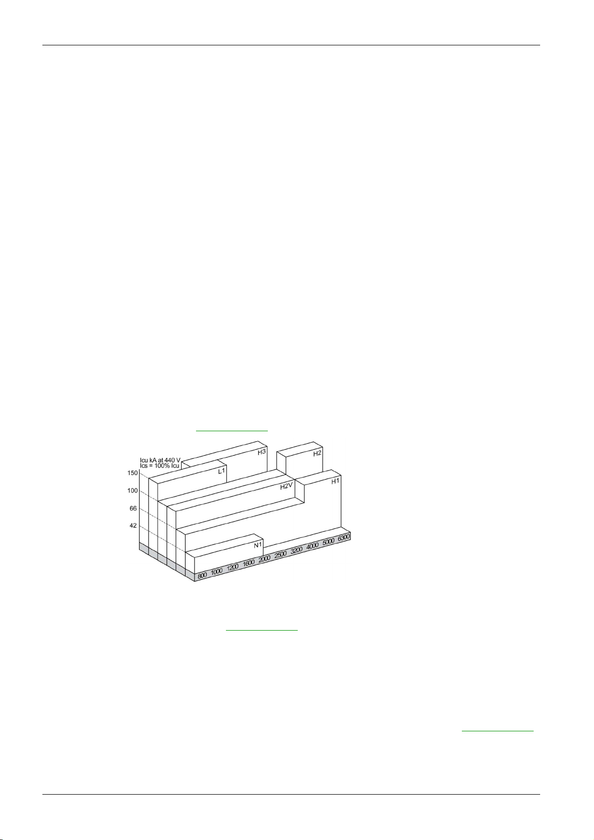
The following performance levels are available:
N1: standard short-circuit level (42 kA) with total selectivity
H1: high short-circuit level (66 kA) with total selectivity
H2: very high short-circuit level (100 kA) with very high selectivity (85 kA)
H2V: very high short-circuit level (100 kA) with very high selectivity (100 kA) (Rated operational voltage
Ue limited to 440 Vac)
H3: extremely high short-circuit level (150 kA) with high selectivity (66 kA)
L1: extremely high short-circuit level (150 kA) with strong current limitation and significant selectivity
(30 kA)
NOTE: The values above correspond to a 440 Vac network, for higher voltage levels the values can be
different. Refer to
MasterPact MTZ device
covers circuit breakers and switch-disconnectors.
LVPED216026EN MasterPact MTZ Catalogue
.
Switch-Disconnectors
10
Circuit breakers are fitted with a MicroLogic X control unit.
For full information about available circuit breaker models, frame sizes, interrupting ratings, sensor ratings,
and control units, refer to
LVPED216026EN MasterPact MTZ Catalogue
.
The following performance levels are available:
NA: Icw = 42 kA/1s
HA: Icw = 66 kA/1s
HF: Icw = 85 kA/1s
HH: Icw = 100 kA/1s
For information about available switch-disconnector models and frame sizes, refer to
MasterPact MTZ Catalogue
.
LVPED216026EN
DOCA0101EN-04 07/2020

Neutral Position on 4P Devices
On 4P circuit breakers:
For MasterPact MTZ2 N1, H3, L1, H10, the neutral position is on the left side as standard.
For MasterPact MTZ2 H1, H2, and H2V, the neutral position is on the left side as standard. A version
with neutral position on the right side is available when ordering.
For MasterPact MTZ3 H1, H2, the neutral position is on the left side as standard. A version with neutral
position on the right side is available when ordering.
On 4P switch-disconnectors:
For MasterPact MTZ2 NA, HA, HF, the neutral position can be switched from the left side to the right
side using the label provided.
For MasterPact MTZ2 HH, the neutral position is on the left side as standard. A version with neutral
position on the right side is available when ordering.
For MasterPact MTZ3 HA, the neutral position is on the left side as standard.
MasterPact MTZ2/MTZ3 Description
DOCA0101EN-04 07/2020 11
MasterPact MTZ2/MTZ3 Description
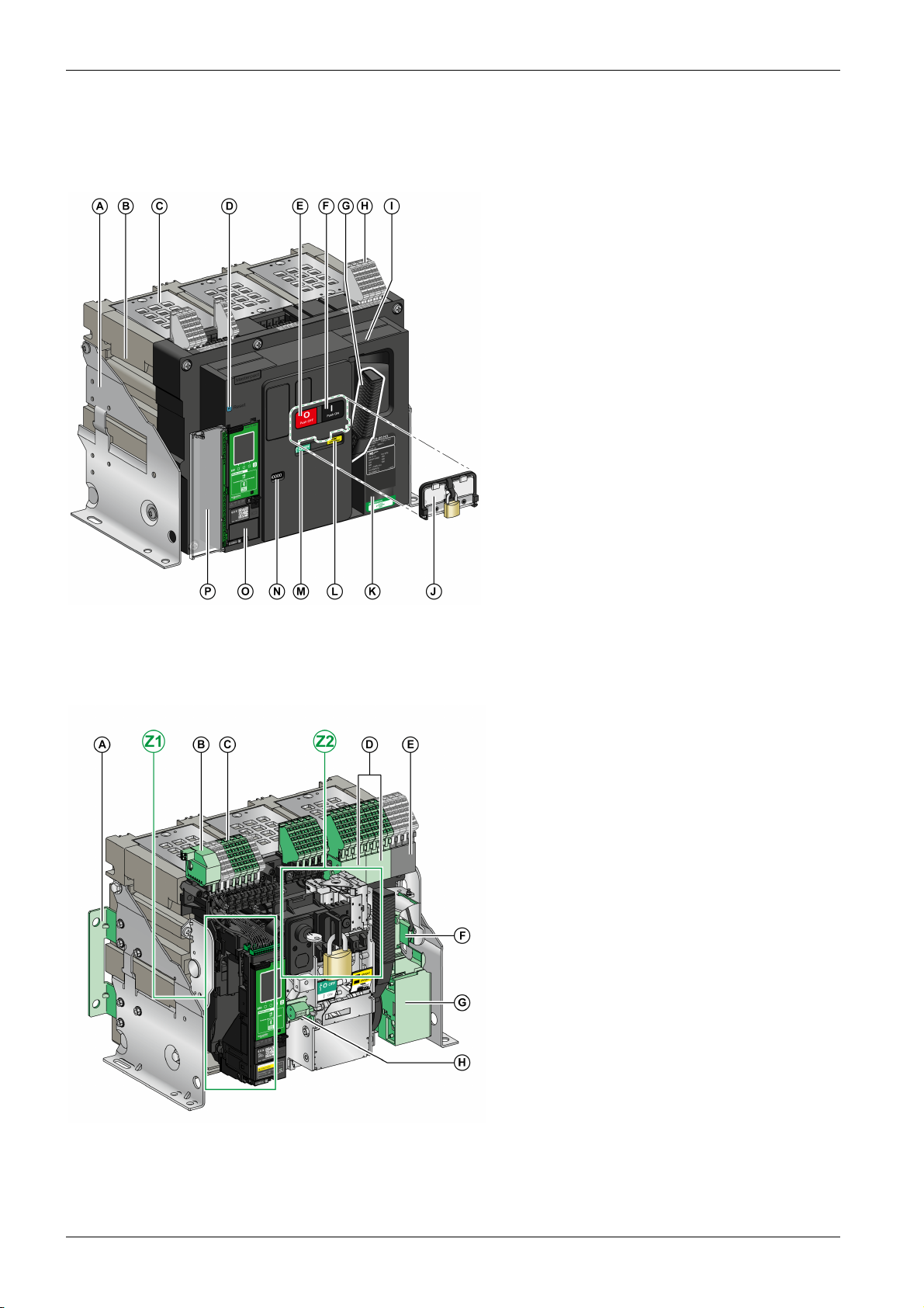
Fixed Device
Fixed Device Description
The following image shows the standard version of the fixed device (no optional accessories).
A Mounting side plate
B Carrying grip
C Arc chute
D Blue fault-trip reset button
E Opening pushbutton
F Closing pushbutton
G Spring charging handle
H Terminal blocks for standard accessories
I Front cover
J VBP pushbutton locking cover (optional)
K Rating plate
L Spring charged and ready-to-close indicator
M Main-contact position indicator
N Window to read the (optional) CDM mechanical
operation counter
O Control unit
P Control unit transparent cover
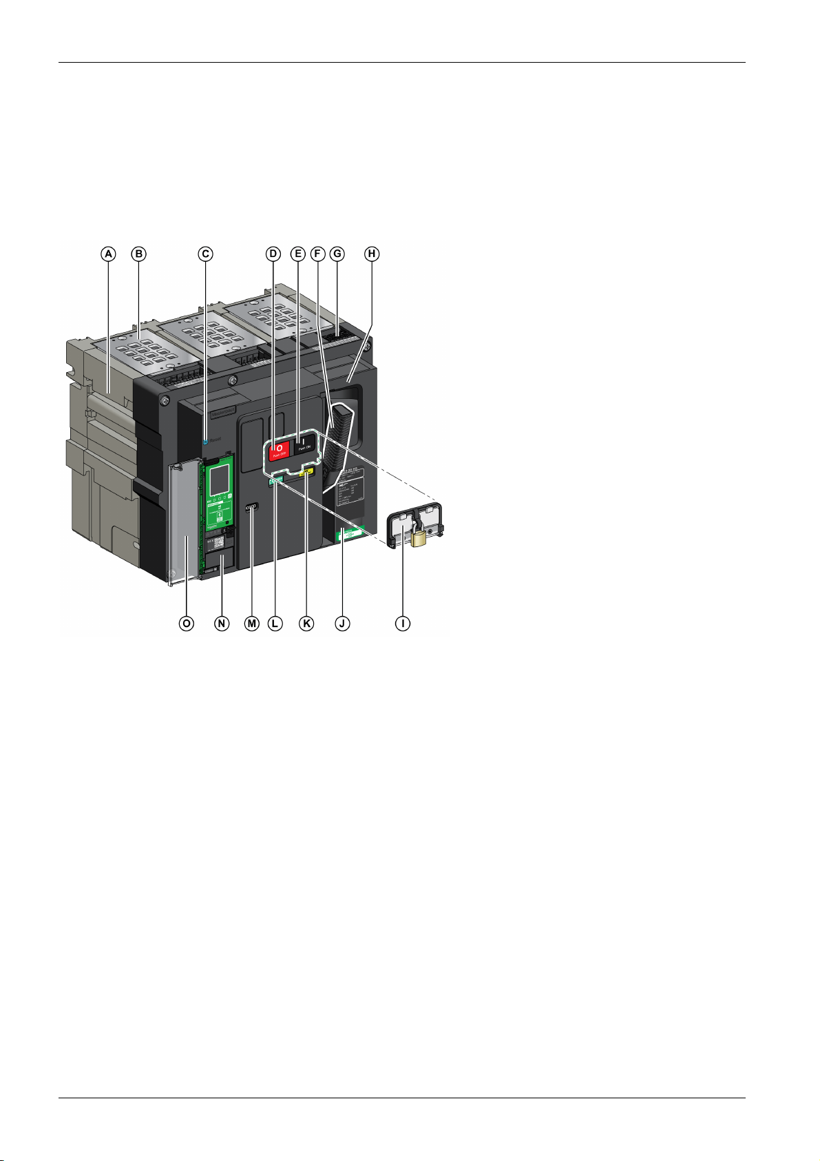
Fixed Device Accessories Description
The following image shows the accessories available for the fixed device.
A Additional support brackets for mounting on a
backplate
B ULP port module
C Terminal blocks for optional accessories
D Four OF indication contacts (optional)
E Four OF indication contacts (delivered as
standard)
F KMT grounding kit
G MCH gear motor
H CDM mechanical operation counter
Z1, Z2 See following images
12
DOCA0101EN-04 07/2020
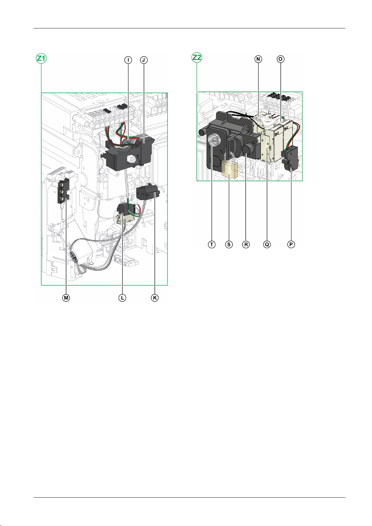
The following images zoom in on the accessories for the fixed device:
MasterPact MTZ2/MTZ3 Description
I Standard SDE1 fault-trip indication contact
J Optional SDE2 fault-trip indication contact or RES electrical
remote reset
K Microswitch
L M2C programmable contacts or ESM ERMS switch module
M Isolation module
N MN undervoltage release or MX2 opening voltage release
O MX1 opening voltage release
P PF ready-to-close contact
Q XF closing voltage release
R BPFE electrical closing pushbutton
S VCPO OFF-position locking by padlocks
T VSPO OFF-position locking by keylocks
DOCA0101EN-04 07/2020 13

MasterPact MTZ2/MTZ3 Description
Fixed Device Terminal Block Description
Terminal block supplied as standard on the circuit breaker
Terminal block for optional accessories on the circuit breaker
14
DOCA0101EN-04 07/2020
Assignment of Terminal Blocks
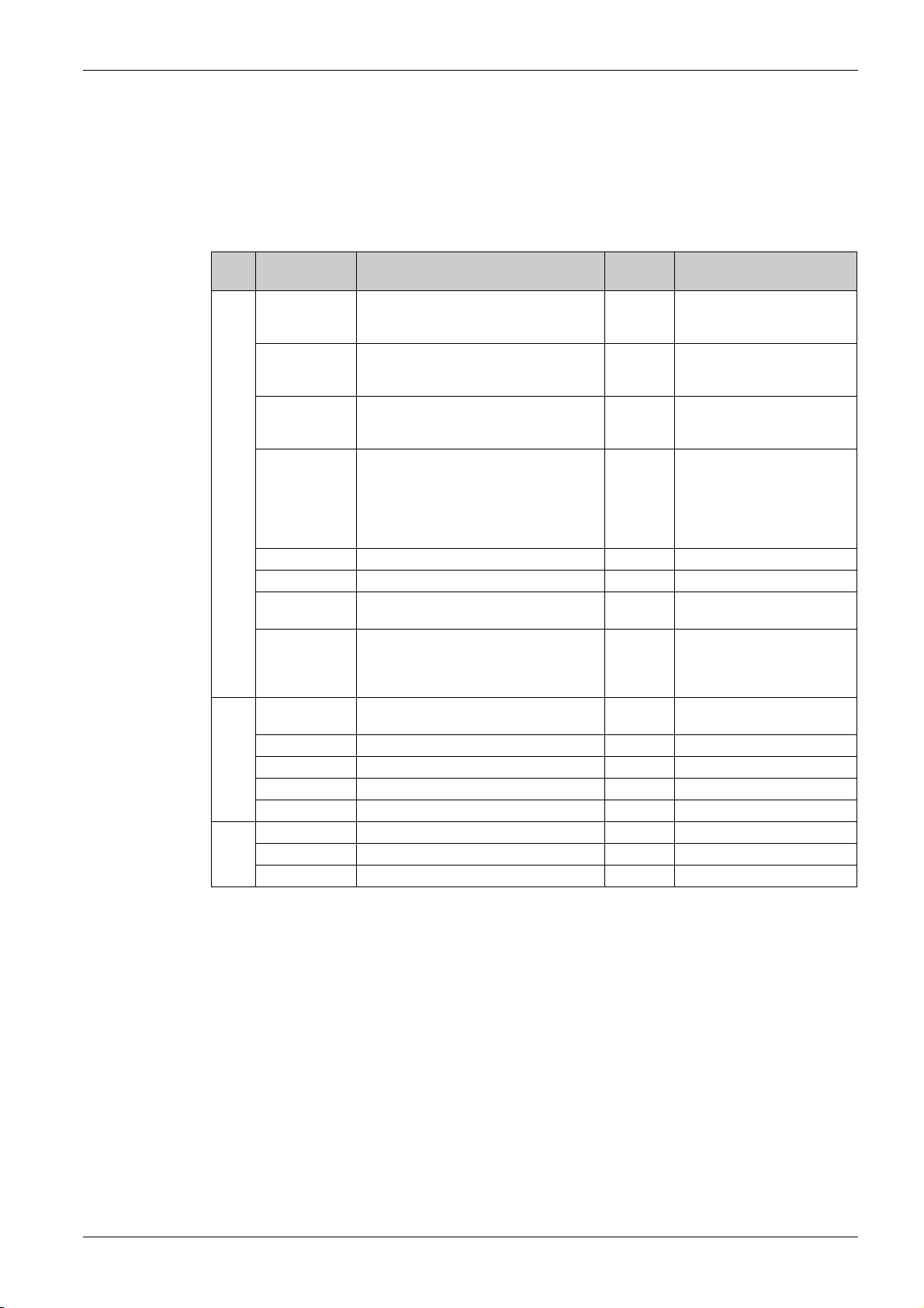
The following table describes the assignment and the availability of the terminal blocks for circuit breakers
and switch-disconnectors for fixed devices:
Standard terminal blocks and the associated accessories are delivered with the device.
Optional terminal blocks are delivered with the device only if the associated optional accessories are
installed in the device.
N/A indicates that the terminal blocks and the associated optional accessories are not compatible with
the device.
MasterPact MTZ2/MTZ3 Description
Block Marking Description Circuit
breaker
A COM Terminal block for the external power supply
of the MicroLogic X control unit
or ULP port module
UC1 Zone selective interlocking (ZSI),
rectangular sensor for earth-leakage
protection, or MDGF module input
UC2 Neutral external sensor, rectangular sensor
for earth-leakage protection, or MDGF
module input
SDE2/RES SDE2 additional fault-trip indication contact
or RES electrical remote reset
UC4 External voltage connector Optional N/A
UC3 External voltage connector Optional N/A
M2C/ESM M2C programmable contacts or ESM ERMS
switch module
SDE1 SDE1 fault-trip indication contact Standard N/A on MasterPact MTZ NA,
B MN/MX2 MN undervoltage release
or MX2 opening voltage release
MX1 MX1 opening voltage release Optional Optional
XF XF closing voltage release Optional Optional
PF PF ready-to-close contact Optional Optional
MCH MCH gear motor Optional Optional
C OF21–OF24 4 OF indication contacts Optional Optional
OF11–OF14 4 OF indication contacts Optional Optional
OF1–OF4 4 OF indication contacts Standard Standard
Standard
Optional
Standard N/A
Standard N/A
Optional N/A on MasterPact MTZ NA,
Optional N/A
Optional Optional
Switch-disconnector
N/A
N/A
HA, HA10
Optional on MasterPact MTZ2
HF, HH
N/A
HA, HA10
Standard on MasterPact MTZ2
HF, HH
DOCA0101EN-04 07/2020 15
MasterPact MTZ2/MTZ3 Description
Drawout Device
Definition
A drawout device is composed of the moving part (also called the device) and the fixed part (or chassis).
Drawout Device Moving Part Description
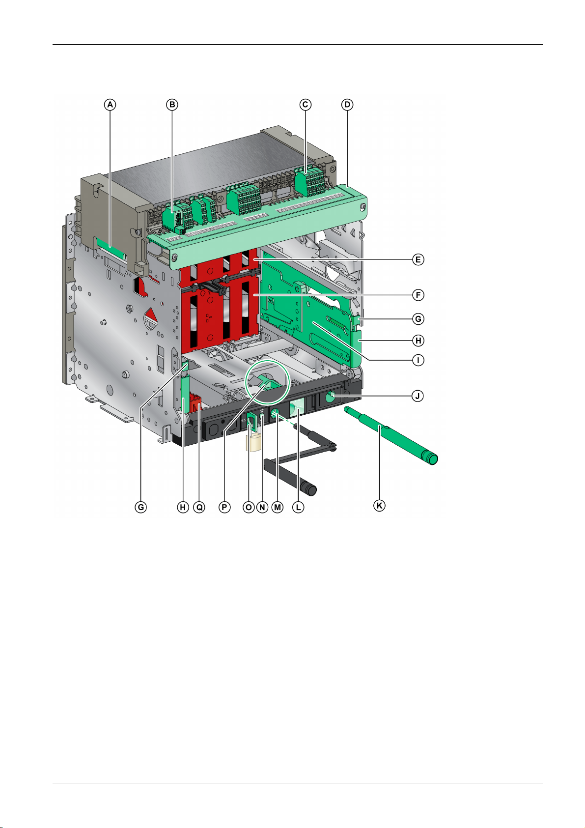
The following image shows the standard version of the moving part of a drawout device (no optional
accessories).
A Carrying grip
B Arc chute
C Blue fault-trip reset button
D Opening pushbutton
E Closing pushbutton
F Spring charging handle
G Terminal block connectors
H Front cover
I VBP pushbutton locking cover (optional)
J Rating plate
K Spring charged and ready-to-close indicator
L Main-contact position indicator
M Window to consult the (optional) CDM
mechanical operation counter
N Control unit
O Control unit transparent cover
16
DOCA0101EN-04 07/2020
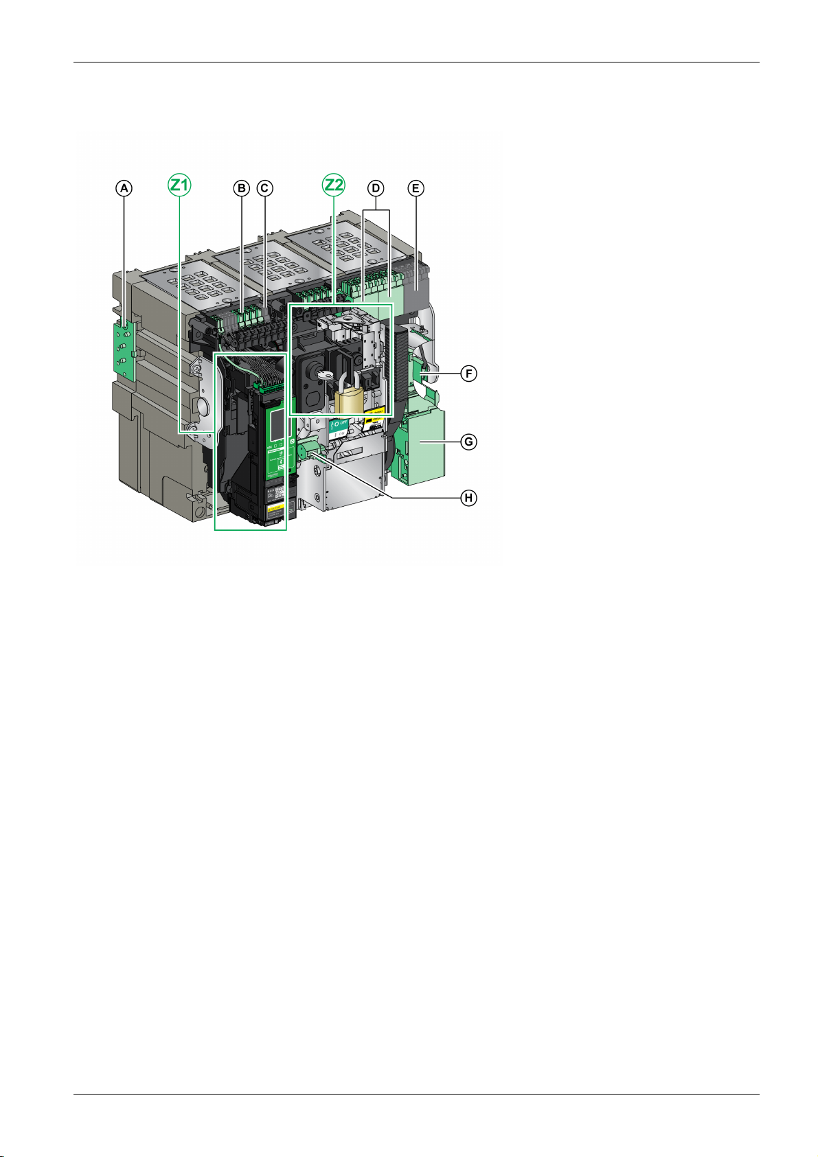
Drawout Device Accessories Description
The following image shows the accessories available for the moving part of a drawout device.
MasterPact MTZ2/MTZ3 Description
A VDC mismatch protection
B Terminal block connectors for optional
accessories
C Terminal block connectors for standard
accessories
D Optional block of four OF indication contacts
or EF combined connected/closed contacts
E Four OF indication contacts (delivered as
standard)
F KMT grounding kit
G MCH gear motor
H CDM mechanical operation counter
Z1, Z2 See following images
DOCA0101EN-04 07/2020 17
MasterPact MTZ2/MTZ3 Description
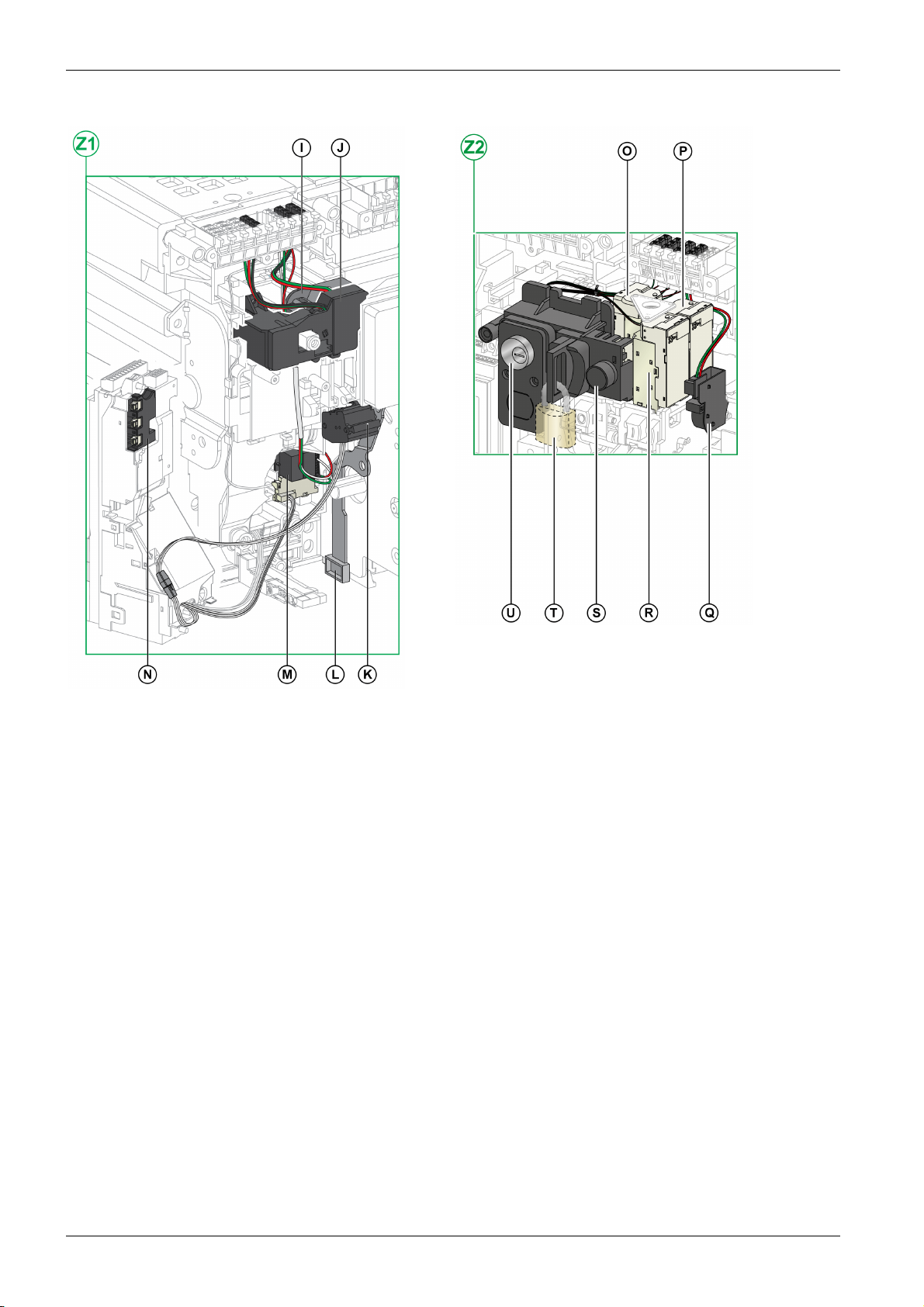
The following images zoom in on the accessories for the moving part of a drawout device.
I Standard SDE1 fault-trip indication contact
J Optional SDE2 fault-trip indication contact or RES electrical
remote reset
K Microswitch
L IBPO interlock between racking handle and opening pushbutton
M M2C programmable contacts or ESM ERMS switch module
N Isolation module
O MN undervoltage release or MX2 opening voltage release
P MX1 opening voltage release
Q PF ready-to-close contact
R XF closing voltage release
S BPFE electrical closing pushbutton
T VCPO OFF-position locking by padlocks
U VSPO OFF-position locking by keylocks
18
DOCA0101EN-04 07/2020
Chassis Description
MasterPact MTZ2/MTZ3 Description
The following image shows the standard version of the chassis (no optional accessories).
A Carrying grip
B ULP port module
C Terminal blocks supplied as standard
D Terminal block identification plate
E Top safety shutter
F Bottom safety shutter
G Rail release tab
H Drawout grip
I Extension rail
J Racking handle storage space
DOCA0101EN-04 07/2020 19
K Racking handle
L Moving part position indicator
M Racking handle socket
N Position release button
O Chassis locking by padlocks
P Latch for switching chassis locking from disconnected position to
any position (connected, test, disconnected)
Q Shutter locking block
MasterPact MTZ2/MTZ3 Description
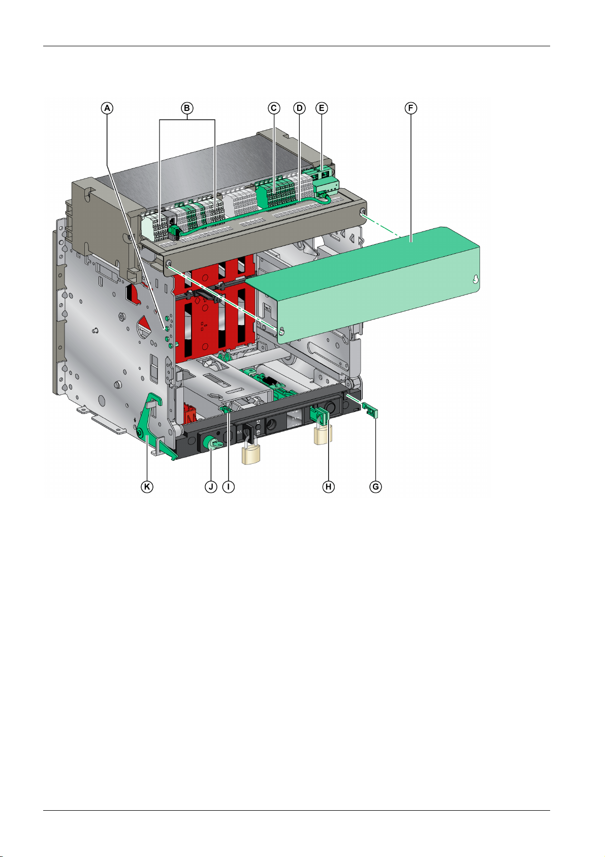
Chassis Accessories Description
The following image shows the accessories available for the chassis.
A VDC mismatch protection
B Drawout device position contacts
C Optional terminal block
D Cord between ULP port module and EIFE interface
E EIFE embedded Ethernet interface
F Circuit breaker auxiliary terminal shield
G VPOC open-door racking interlock
H VIVC shutter position indication and locking
I IBPO interlock between racking handle and opening pushbutton
J VSPD chassis locking by keylocks
K VPEC door interlock
20
DOCA0101EN-04 07/2020
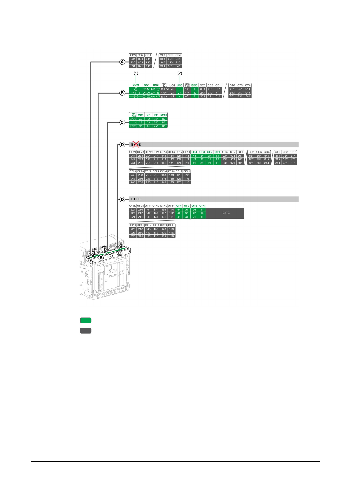
Chassis Terminal Block Description
MasterPact MTZ2/MTZ3 Description
Terminal block supplied as standard on the chassis
Optional terminal block on the chassis
(1) Supplied as standard with chassis for MasterPact MTZ2/MTZ3 circuit breakers only
(2) Supplied as standard with 3P chassis only
DOCA0101EN-04 07/2020 21
MasterPact MTZ2/MTZ3 Description
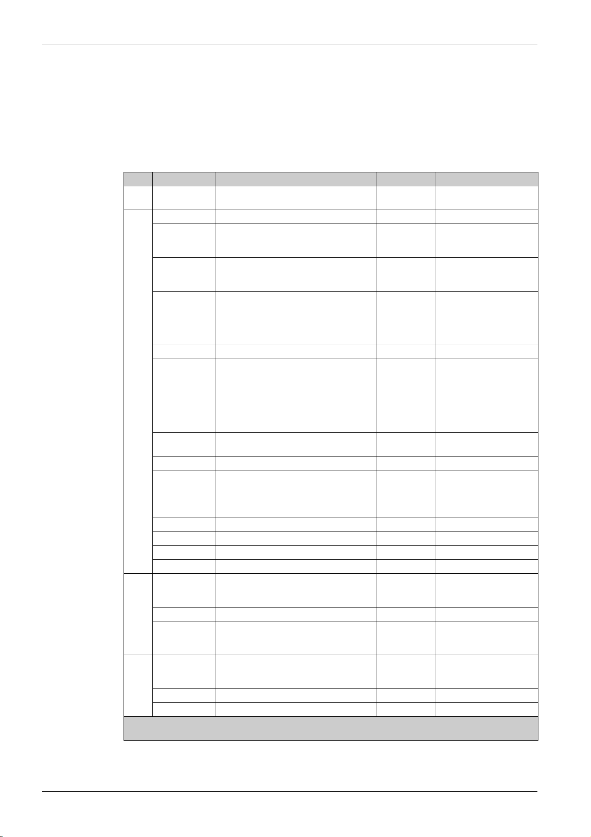
Assignment of Terminal Blocks
The following table describes the assignment and the availability of the terminal blocks for circuit breakers
and switch-disconnectors for drawout devices:
Standard terminal blocks are delivered on the chassis, even if the associated optional accessories are
not installed in the device.
Optional terminal blocks are delivered on the chassis only if the associated optional accessories are
installed in the device.
N/A indicates that the terminal blocks and the associated optional accessories are not compatible with
the device.
Block Marking Description Circuit breaker Switch-disconnector
A CD1–CD3
CE4–CE6
B COM ULP port module Standard N/A
UC1 Zone selective interlocking (ZSI), rectangular
UC2 Neutral external sensor, rectangular sensor
SDE2/RES SDE2 additional fault-trip indication contact
UC4 External voltage connector Optional N/A
UC3 External voltage connector Standard on
3 CD disconnected position contacts
or 3 CE connected position contacts
sensor for earth-leakage protection, or
MDGF module input
for earth-leakage protection, or MDGF
module input
or RES electrical remote reset
Optional Optional
Standard Standard
Standard Standard
Optional N/A on MasterPact MTZ
NA, HA, HA10
Optional on
MasterPact MTZ2 HF, HH
N/A
Standard on 3P switch-
3P circuit
disconnectors
breakers
Optional on 4P
circuit
breakers
M2C/ESM M2C programmable contacts
Optional N/A
or ESM ERMS switch module
SDE1 SDE1 fault-trip indication contact Standard Standard
CE1–CE3
CT4–CT6
C MN/MX2 MN undervoltage release
3 CE connected position contacts
or 3 CT test position contacts
Optional Optional
Standard Standard
or MX2 opening voltage release
MX1 MX1 opening voltage release Standard Standard
XF XF closing voltage release Standard Standard
PF PF ready-to-close contact Standard Standard
MCH MCH gear motor Standard Standard
(1)
D
OF11–OF24
EF11–EF24
8 OF indication contacts
or 8 EF combined connected/closed position
Optional Optional
auxiliary contacts
OF1–OF4 4 OF indication contacts Standard Standard
Optional Optional
Optional N/A
(2)
D
CT1–CT3
CD4–CD6
CE7–CE9
OF11–OF22
EF11–EF22
3 CT test position contacts
or 3 CD disconnected position contacts
or 3 CE connected position contacts
6 OF indication contacts
or 6 EF combined connected/closed position
auxiliary contacts
OF1–OF4 4 OF indication contacts Standard Standard
EIFE EIFE embedded Ethernet interface Optional N/A
(1) Without EIFE interface
(2) With EIFE interface
N/A on 4P switchdisconnectors
22
DOCA0101EN-04 07/2020
Device Identification
Identification
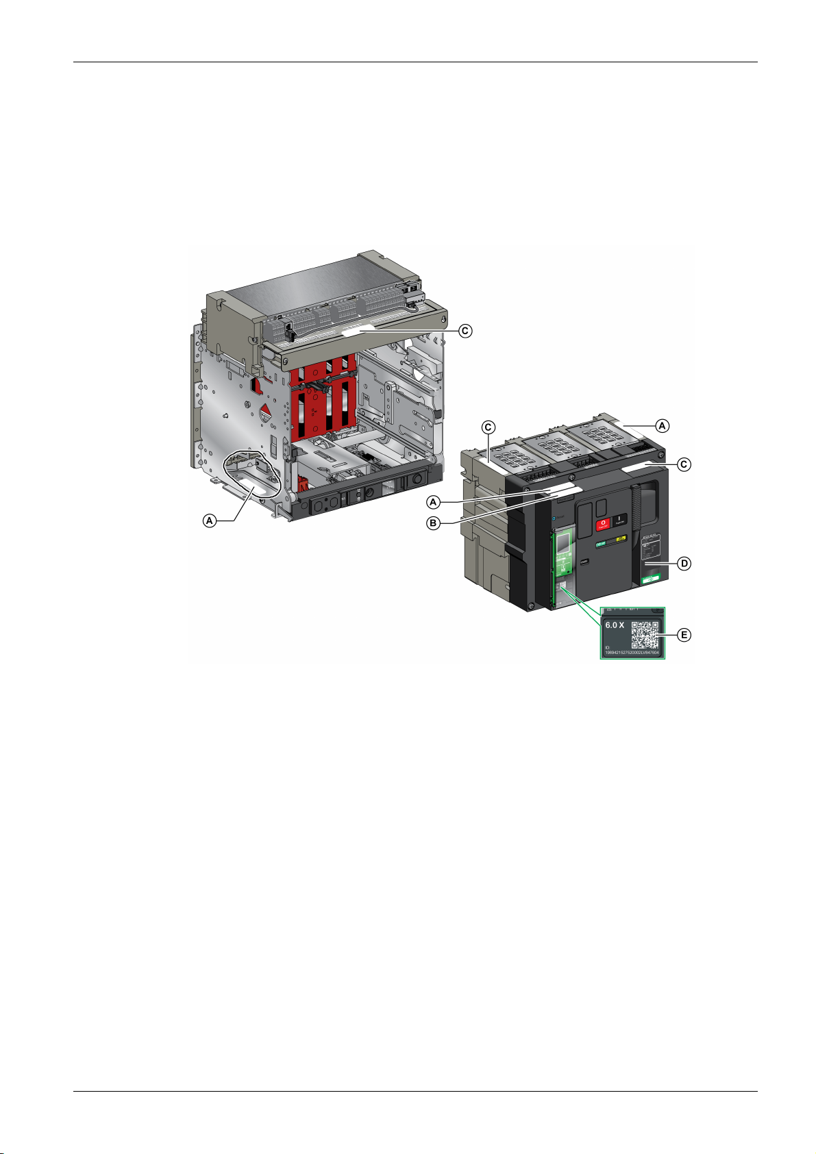
The MasterPact MTZ2/MTZ3 device can be identified in the following ways:
Rating plate on device
QR code located:
Identification labels on the device and on the chassis
MasterPact MTZ2/MTZ3 Description
On the front face of the control unit of the circuit breaker
On the front face of the switch-disconnector
A Product identification label
B Product checked label
C Accessory voltages label
D Rating plate
E QR code to access product information
DOCA0101EN-04 07/2020 23
MasterPact MTZ2/MTZ3 Description
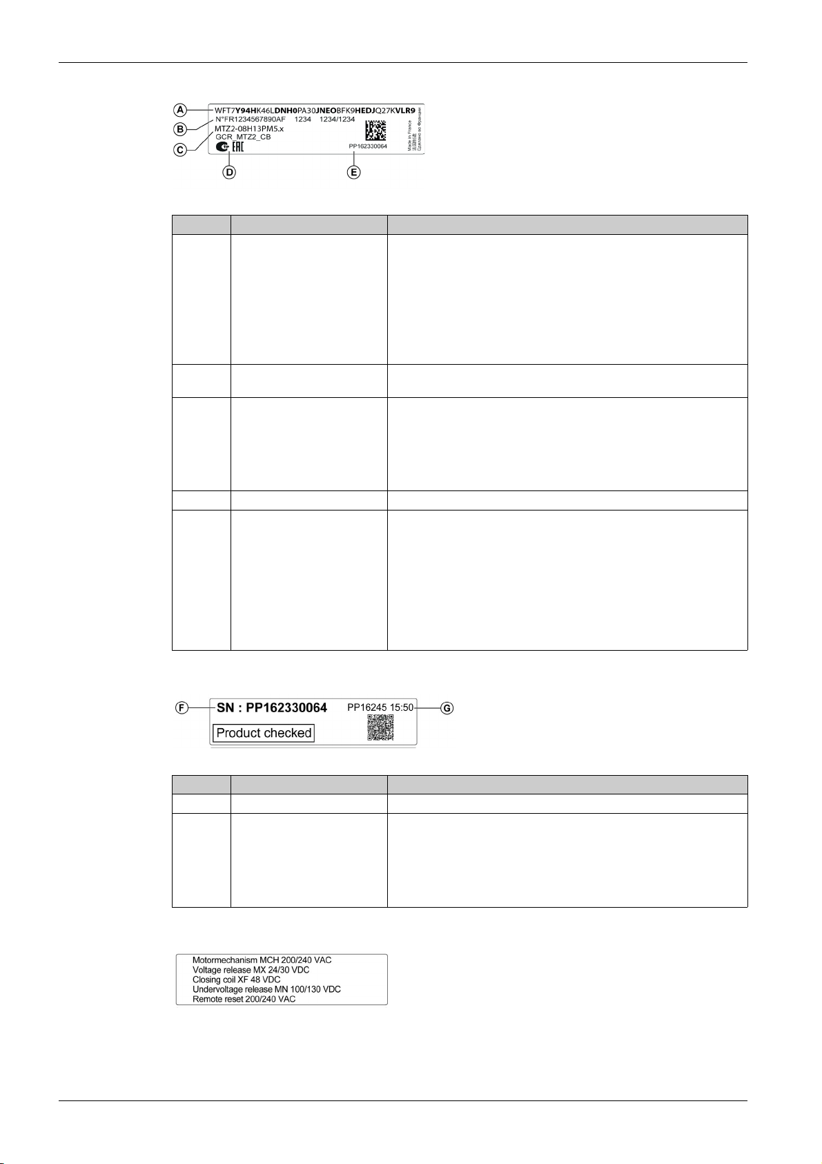
Product Identification Label
Legend Description Explanation
A Product code The product code is a line of code representing the complete
B Schneider Electric internal
C Description of device The description of the device, specifies the following characteristics:
D Certification logos The logos of the mandatory certifications of the device.
E Device serial number The device serial number is coded PPYYWWDXXXX, where:
configuration of a MasterPact circuit breaker or switch-disconnector. It is
automatically generated for each MasterPact device after completing the
configuration using the Product Selector configuration tool.
The product code appears on the invoice and on the delivery documents
as well as on the MasterPact device and packaging labels.
The product code can be entered in the Product Selector configuration
tool, which generates the complete configuration of the MasterPact
device.
–
identification numbers
Range
Rating
Performance level
Number of poles
Control unit type
PP: Plant code
YY: Year of manufacture
WW: Week of manufacture
D: Day of the week of manufacture (Monday = 1)
XXXX: The production number of the product on the day. Ranges from
0001 to 9999
For example, PP162330064 is the sixty fourth device manufactured at
plant PP on Wednesday, June 8, 2016.
Product Checked Label
Legend Description Explanation
F Device serial number See explanation in preceding table.
G Device test date code The device test date code is coded PPYYWWD HH:MM, where:
Accessory Voltages Label
The accessory voltages label gives the voltage of the accessories which are installed in the device and
which need to be connected to a power supply.
PP: plant code
YY: year of test
WW: week of test
D: day of the week of test (Monday = 1)
HH:MM: the time of test in hours and minutes
24
DOCA0101EN-04 07/2020
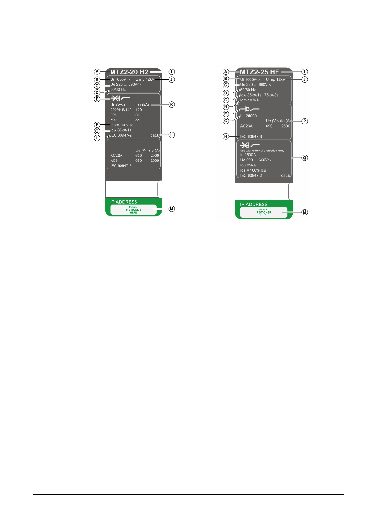
Rating Plate
MasterPact MTZ2/MTZ3 Description
The rating plate with the device information is located on the front cover of the device.
Circuit breaker rating plate Switch-disconnector rating plate
QR Code
A Device size and rated current x 100 A
B Ui: rated insulation voltage
C Ue: rated operational voltage
D Frequency
E Type of device: circuit breaker or switch-disconnector,
suitable for insulation
F Ics: rated service short-circuit breaking capacity
G Icw: rated short-time withstand current
H Standards
I Performance level
J Uimp: rated impulse withstand voltage
K Icu: rated ultimate short-circuit breaking capacity
L Selectivity category as per IEC 60947-2
M Place for sticker with IP address of the optional EIFE
interface
N Icm: rated short-circuit making capacity
O Ith: conventional free air thermal current
P Ie: rated operational current
Q Information related to switch-disconnectors used as
unprotected circuit breakers
When the QR code on the front face of a MasterPact MTZ device is scanned with a smartphone running a
QR code reader and connected to the Internet, the Go2SE landing page is displayed
(see page 29)
. The
landing page displays some information about the device and a list of menus.
DOCA0101EN-04 07/2020 25
MasterPact MTZ2/MTZ3 Description
MicroLogic X Control Unit: Description
Introduction
The MicroLogic X control unit includes:
LEDs to monitor the status of the circuit breaker
A local Human Machine Interface comprising a graphic display with colored backlight, contextual
buttons, and dedicated buttons
LEDs to monitor the cause of trips and alarms
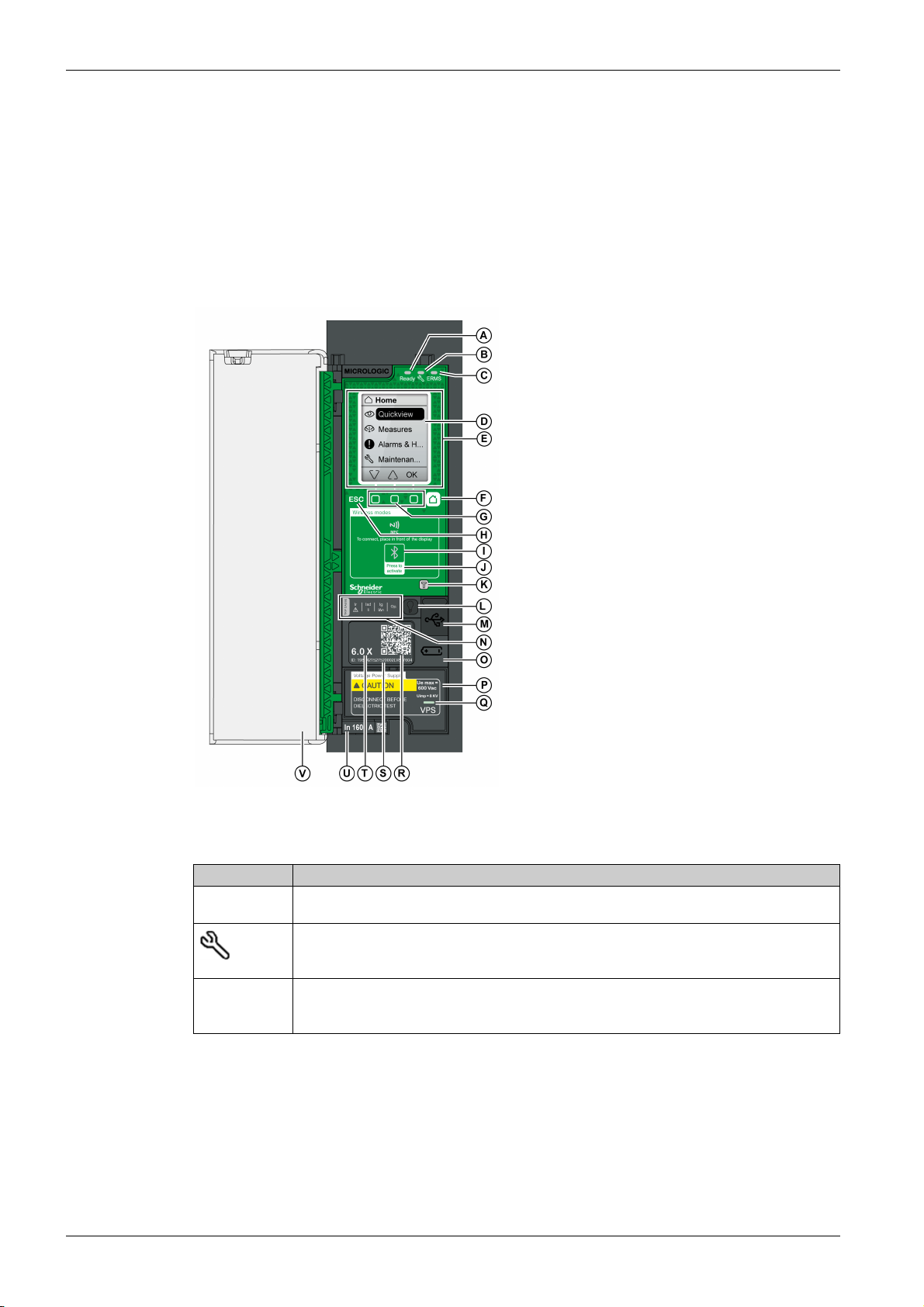
Control Unit Description
A Ready LED
B Service LED
C ERMS LED
D Graphic display screen
E NFC wireless communication zone
F Home button
G Three contextual buttons
H Escape button ESC
I Bluetooth LED
J Bluetooth activation button
K Test button for ground-fault and earth-leakage
protection (MicroLogic 6.0 X and 7.0 X)
L Test/Reset button for trip cause LEDs and alarms
M Mini USB port under rubber cover
N Overload and trip cause LEDs
O Cover for internal battery
P VPS voltage power supply module (optional)
Q VPS LED to indicate that the VPS module is
supplying the control unit
R QR code to access product information
S Control unit identification number
T Control unit type
U Sensor plug with the rated current of the circuit
breaker
V Plastic cover
Status LEDs
LED Description
Ready The Ready LED blinks slowly when the standard protection functions of the control unit are
operational.
The service LED alerts the user to the health state of the circuit breaker.
Orange LED: medium severity detected alarm that requires non-urgent maintenance action.
Red LED: high severity detected alarm that requires immediate maintenance action.
ERMS The ERMS (Energy Reduction Maintenance Setting) LED has the following statuses:
Blue LED: ERMS engaged
Off LED: ERMS disengaged
Display Screen with Contextual Buttons and Dedicated Buttons
The local HMI screen and buttons are used to:
Navigate the menu structure.
Display monitored values.
Access and edit configuration settings.
26
DOCA0101EN-04 07/2020
NFC Communication Zone
The NFC communication zone is used to establish an NFC connection between a smartphone running the
EcoStruxure Power Device app and the MicroLogic X control unit. When the connection is established, the
circuit breaker operating data is automatically uploaded to the smartphone.
Bluetooth Activation Button and LED
The Bluetooth activation button is used to establish a Bluetooth low energy connection between a
smartphone running the EcoStruxure Power Device app and the MicroLogic X control unit. When the
connection is established, the circuit breaker can be monitored and controlled from the smartphone.
When the Bluetooth LED is blinking, it indicates that the MicroLogic X control unit is in communication with
a Bluetooth device.
Test Button
The test button is used to test the ground-fault protection for MicroLogic 6.0 X and the earth-leakage
protection for MicroLogic 7.0 X.
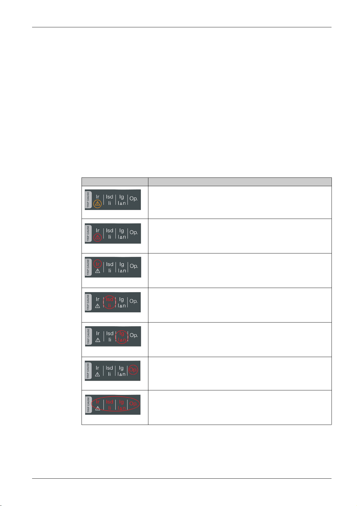
Overload and Trip Cause LEDs
The indications of the four trip cause LEDs depend on the type of MicroLogic X control unit.
LEDs Description
MasterPact MTZ2/MTZ3 Description
MicroLogic 2.0 X, 5.0 X, 6.0 X, 7.0 X: Overload pre-alarm, the load exceeds 90%
and is lower than 105% of the Ir setting of the long-time protection.
o
MicroLogic 2.0 X, 5.0 X, 6.0 X, 7.0 X: Overload alarm, the load exceeds 105% of
the Ir setting of the long-time protection.
MicroLogic 2.0 X, 5.0 X, 6.0 X, 7.0 X: Trip due to long-time protection.
MicroLogic 2.0 X: Trip due to instantaneous protection.
MicroLogic 5.0 X, 6.0 X, 7.0 X: Trip due to short-time protection or instantaneous
protection.
MicroLogic 2.0 X, 5.0 X: Not applicable.
MicroLogic 6.0 X: Trip due to ground-fault protection.
MicroLogic 7.0 X: Trip due to earth-leakage protection.
MicroLogic 2.0 X, 5.0 X, 6.0 X, 7.0 X: Trip due to optional protections.
MicroLogic 2.0 X, 5.0 X, 6.0 X, 7.0 X: MicroLogic control unit invalid result detected
during self test.
NOTE: If the MicroLogic X control unit is not powered, the trip cause LEDs go off after 4 hours. After this
period, press the Test/Reset button to light them again.
DOCA0101EN-04 07/2020 27

MasterPact MTZ2/MTZ3 Description
Test/Reset Button
The Test/Reset button performs the following functions:
Test of the internal battery or check LED functionality: press and hold the Test/Reset button for less than
3 seconds, the four trip cause LEDs switch off for one second. One of the following results:
The four trip cause LEDs switch on for two seconds: the battery is OK.
The four trip cause LEDs flash sequentially for two seconds: the battery is near the end of its life.
Replace the battery.
The four trip cause LEDs do not light: replace the battery.
NOTE: This test must be carried out immediately after the replacement of the internal battery to check
the correct functioning of the new battery. It can then be carried out at any time in the life of the internal
battery.
Reset of the latched events: press and hold the Test/Reset button for more than 3 seconds to reset the
latched events. The trip cause LEDs and the service LED switch off.
Mini USB Port
Remove the rubber cover of the mini USB port to connect the following devices:
A Mobile Power Pack to supply power to the MicroLogic X control unit.
A smartphone running the EcoStruxure Power Device app through USB OTG connection.
A PC running EcoStruxure Power Commission software.
NOTE: The MicroLogic X control unit does not support USB keys. Even if a USB key is connected using
an adapter, data is not transferred.
QR Code
When the QR code on the front face of a MicroLogic X control unit is scanned with a smartphone running
a QR code reader and connected to the Internet, the Go2SE landing page is displayed
landing page displays some information about the device and a list of menus.
Control Unit Identification Number
The identification number is made up as follows:
The serial number of the MicroLogic X control unit in the format FFFFFFYYWWDLXXXX
The commercial reference of the control unit in the format LV8•••••
Use the identification number to register your MicroLogic X control unit through mySchneider app, the
customer care mobile application.
Registering your MicroLogic X control unit enables you to keep your records up to date and enables
traceability.
Control Unit Type
This code indicates the type of MicroLogic control unit:
The number (for example, 6.0) defines the types of protection provided by the control unit.
The letter (X) identifies the range of the control unit.
Internal Battery
The internal battery powers the trip cause LEDs and the main diagnostic functions in the absence of any
other power supply.
(seepage29)
. The
VPS Voltage Power Supply Module
The VPS module provides an internal voltage supply to the MicroLogic X control unit.
The VPS module is optional for MicroLogic 2.0 X, 5.0 X, and 6.0 X. It is installed as standard on
MicroLogic 7.0 X.
Sensor Plug
The protection ranges depend on the rated current In, defined by the sensor plug present below the
MicroLogic X control unit.
28
DOCA0101EN-04 07/2020
Go2SE Landing Page
Presentation
When the QR code on the front face of a MasterPact MTZ device is scanned with a smartphone running a
QR code reader and connected to the Internet, the Go2SE landing page is displayed.
The landing page displays information about the device and a list of menus.
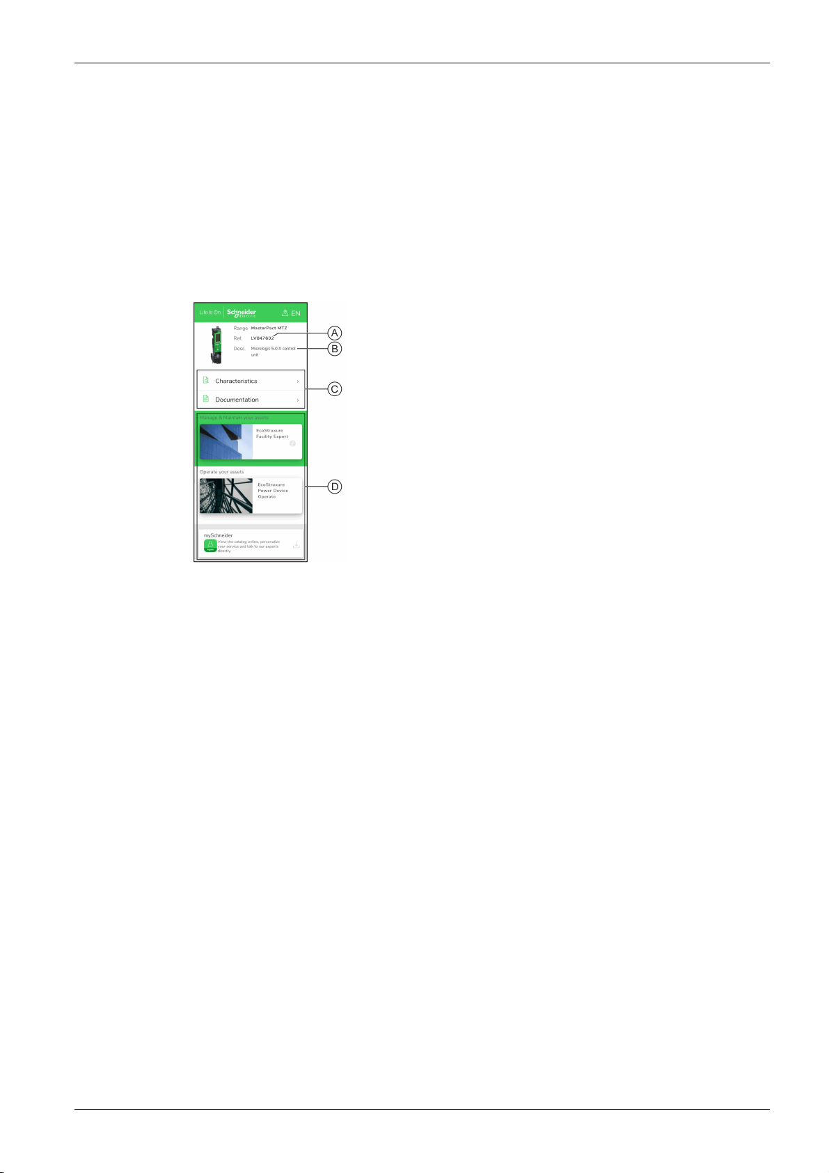
Landing Page Description
The landing page is accessible from Android and iOS smartphones. It displays the same list of menus with
slight differences in presentation.
The following example shows the landing page displayed on an Android smartphone:
MasterPact MTZ2/MTZ3 Description
A Commercial reference of MicroLogic X control unit
B Type of MicroLogic X control unit
C Landing page menus. See the following menu descriptions
for details.
D Downloadable applications
Characteristics
Documentation
Selecting this menu gives access to a product datasheet with detailed information about the MicroLogic X
control unit.
Selecting this menu gives access to a sub-menu with the following options:
Asset Life Cycle Documents: gives access to Safe Repository.
Safe Repository is a web service allowing documentation linked to assets to be consulted, stored, and
shared in a Schneider Electric environment. Access to Safe Repository is restricted to authorized users.
Safe Repository gives access to the bill of materials of the MasterPact MTZ circuit breaker.
Technical Guidance at Glance: gives access to the MasterPact MTZ technical publications, including:
MasterPact MTZ - MicroLogic X Control Unit - User Guide
MasterPact MTZ1 - Circuit Breakers and Switch-Disconnectors - User Guide
MasterPact MTZ2/MTZ3 - Circuit Breakers and Switch-Disconnectors - User Guide
All the instruction sheets for MasterPact MTZ devices and MicroLogic X control units
Product Documentation: gives access to the MicroLogic X technical publications
DOCA0101EN-04 07/2020 29

MasterPact MTZ2/MTZ3 Description
EcoStruxure Facility Expert App
Selecting this application gives access to the EcoStruxure Facility Expert mobile application that can be
downloaded on Android and iOS smartphones. For smartphone compatibility, check on your application
store.
EcoStruxure Facility Expert optimizes operations and maintenance, helping to ensure business continuity,
and provides insights to service providers or facility managers.
EcoStruxure Facility Expert is a real-time collaborative technology available on mobile devices and PCs
that enables managers and maintenance personnel to be connected with facilities and equipment.
Information exchange between users is simple and fast.
The QR code on MasterPact MTZ devices enables managers and maintenance personnel to access the
following automatic downloads:
MasterPact MTZ device identifier.
Technical documentation.
The maintenance plan for the MasterPact MTZ device.
EcoStruxure Facility Expert enables managers and maintenance personnel to access the maintenance
plan for MasterPact MTZ devices.
EcoStruxure Facility Expert helps maintenance personnel to diagnose issues remotely and manage
maintenance efficiently by:
Providing relevant information on critical assets.
Sending immediate state of the equipment and detailed information helping for diagnostics.
EcoStruxure Power Device App
Selecting this application gives access to the EcoStruxure Power Device app that can be downloaded and
installed on Android and iOS smartphones. For smartphone compatibility, check on your application store.
mySchneider App
Selecting this application gives access to the Schneider Electric customer care mobile application
mySchneider app that can be downloaded on Android and iOS smartphones. For smartphone
compatibility, check on your application store. The customer care application offers self-service
instructions and easy access to expert support and information.
30
DOCA0101EN-04 07/2020

Operating Conditions
Introduction
MasterPact MTZ devices are designed and tested for operation in industrial atmospheres. It is
recommended that equipment is cooled or heated to the proper operating temperature and kept free of
excessive vibration and dust.
Ambient Temperature
MasterPact MTZ devices can operate under the following temperature conditions:
Electrical and mechanical characteristics specified for an ambient temperature of -25 °C to +70 °C .
Circuit-breaker closing specified down to -35 °C by manual operation with closing pushbutton.
Storage conditions are as follows:
-40 °C to +85 °C for the device without the control unit.
-25 °C to +85 °C for the control unit.
Extreme Atmospheric Conditions
MasterPact MTZ devices have successfully passed tests for extreme atmospheric conditions, defined by
the following standards:
Standard Title
IEC 60068-2-1 Dry cold, at -40 °C
IEC 60068-2-2 Dry heat, at +85 °C
IEC 60068-2-30 Damp heat (temperature +55 °C, relative humidity 95%)
IEC 60068-2-52 level 2 Salt mist
MasterPact MTZ2/MTZ3 Description
Industrial Environments
MasterPact MTZ devices can operate in the industrial environments defined by IEC 60947 (pollution
degree up to 3).
It is advisable to check that devices are installed in suitably cooled switchboards without excessive dust.
Conditions Standard
Corrosive industrial atmospheres Category 3C3 compliant with IEC 60721-3-3
Sea salts 0.8 to 8 mg/m² day average over the year Compliant with IEC 60721-2-5
Mechanically active substances Category 3S3 compliant with IEC 60721-3-3
Beyond these conditions, MasterPact MTZ devices must be installed inside switchboards with an IP rating
equal to or greater than IP54.
Vibration
MasterPact MTZ devices have successfully passed tests for the following vibration levels, in compliance
with IEC 60068-2-6 and IEC 60068-2-27:
2 Hz to 13.2 Hz: amplitude +/- 1 mm.
13.2 Hz to 100 Hz: constant acceleration of 0.7 g.
Vibration testing to these levels is required by merchant marine inspection organizations (for example,
Veritas, Lloyd’s).
MasterPact MTZ devices have also been successfully tested according to:
Annex Q - IEC 60947-1: Special tests – damp heat, salt mist, vibration and shock
IEC 60947-1 - Category D: Environment subject to temperature, humidity and vibration
DOCA0101EN-04 07/2020 31

MasterPact MTZ2/MTZ3 Description
Altitude
MasterPact MTZ devices are designed and tested to operate at altitudes below 2,000 m.
At altitudes above 2,000 m, the characteristics of the ambient air (electrical resistance, cooling capacity)
lower product characteristics as follows:
Characteristics Altitude
Impulse withstand voltage Uimp (kV) 12 11 10 8
Rated insulation voltage (Ui) (V) 1,000 900 780 700
Maximum rated operational
voltage 50/60 Hz Ue (V)
Rated current (A) at 40 °C 1 x In 0.99 x In 0.96 x In 0.94 x In
NOTE: Intermediate values can be obtained by interpolation.
Electromagnetic Disturbances
MasterPact MTZ devices have protection against:
Overvoltages caused by devices that generate electromagnetic disturbance.
Overvoltages caused by atmospheric disturbance or by a distribution-system outage (for example, a
lighting system failure).
Devices emitting radio waves (for example, radio transmitters, walkie-talkies, or radar).
Electrostatic discharge produced by users.
MasterPact MTZ devices have successfully passed the electromagnetic-compatibility tests (EMC) defined
by the following international standards:
IEC 60947-2, appendix F.
IEC 60947-2, appendix B (control units with earth-leakage function).
The devices have passed the above tests and therefore:
No nuisance tripping occurs.
Tripping times are respected.
2,000 m 3,000 m 4,000 m 5,000 m
MasterPact MTZ2/MTZ3
except H10
MasterPact MTZ2/MTZ3 H10 1,000 890 795 700
690 690 630 560
32
DOCA0101EN-04 07/2020

MasterPact MTZ2/MTZ3
MasterPactMTZ2/MTZ3 Normal Operation
DOCA0101EN-04 07/2020
MasterPactMTZ2/MTZ3 Normal Operation
Chapter 2
MasterPact MTZ2/MTZ3 Normal Operation
What Is in This Chapter?
This chapter contains the following sections:
Section Topic Page
2.1 Device Operating Actions 34
2.2 Drawout Device Racking Actions 60
2.3 Device Locking Actions 77
2.4 Device Interlocking Actions 93
DOCA0101EN-04 07/2020 33

MasterPact MTZ2/MTZ3 Normal Operation
Device Operating Actions
Section 2.1
Device Operating Actions
What Is in This Section?
This section contains the following topics:
Operating the Device 35
Control Modes 39
Opening the Device 44
Closing the Device 47
Resetting the Circuit Breaker 50
Engaging the ERMS Function 51
Operating Accessories 53
Topic Page
34
DOCA0101EN-04 07/2020

Operating the Device
Device Status
The indicators on the front of the device show the following information:
Reset button:
In: the device is closed or open voluntarily (not tripped)
Out: the device has tripped
Position indicator of main contacts: ON or OFF.
Closing spring and ready-to-close indicator. The state can be one of the following:
Discharged (no energy to close the circuit breaker)
Charged not ready-to-close
Charged ready-to-close
MasterPact MTZ2/MTZ3 Normal Operation
A Reset button
B Position indicator of main contacts
C Closing spring and ready-to-close indicator
The combination of both indicators gives the device status:
Position indicator of main
contacts
Closing spring and readyto-close indicator
Device status description
Device is off (main contacts are open) and closing spring is
discharged.
Device is off (main contacts are open) and closing spring is
charged. The device is not ready-to-close because at least
one of the following conditions is true:
The device has tripped and must be reset.
The MX opening voltage release is energized.
The MN undervoltage release is not energized.
The device is mechanically locked in the open position
by using padlock or keylock or by using an interlocking
system.
Device is off (main contacts are open) and closing spring is
charged.
The device is ready-to-close.
Device is on (main contacts are closed) and closing spring
is discharged.
Device is on (main contacts are closed) and closing spring
is charged.
The device is not ready-to-close because it is already
closed.
DOCA0101EN-04 07/2020 35

MasterPact MTZ2/MTZ3 Normal Operation
Device Indication Contacts
The position of the device main contacts is indicated by OF indication contacts.
Anti-Pumping Function
MasterPact MTZ devices provide a mechanical anti-pumping function. In the event of simultaneous
maintained opening and closing orders, the standard mechanism blocks the main contacts in the open
position. After a trip due to an electrical fault or intentional opening using the manual or electrical controls,
the closing order must first be discontinued, then reactivated to close the circuit breaker. This prevents a
cycle of closing and opening.
When remote operation features are used, allow at least four seconds for the MCH gear motor to charge
the device closing spring completely before the XF closing voltage release is actuated.
To prevent the device from closing prematurely, the PF ready-to-close contact can be series connected
with the XF closing voltage release.
Name Contact
number
Device status – ON OFF Tripped (by
Position indicator of
main contacts
Main contact position – Closed Open Open
Reset button position – IN IN OUT
OF indication contact
position
SDE indication contact
position
–
1–2 Open Closed Closed
1–4 Closed Open Open
1–2 Closed Closed Open
1–4 Open Open Closed
Position of indicators and contacts
MicroLogic X control
unit)
Charging the Closing Spring
The closing spring must be charged with sufficient energy to close the MasterPact MTZ:
Manual charge: Charge the mechanism by pulling the spring charging handle down seven times.
Automatic charge: If the optional MCH gear motor is installed, the spring is automatically charged after
closing.
NOTE: For drawout devices fitted with the optional DAE automatic spring-discharge before device removal
(see page 105)
withdrawn position.
, the closing spring is discharged when the device is moved from disconnected to
36
DOCA0101EN-04 07/2020

Manual Operation Cycle with the Spring Charging Handle
The following image shows an Open/Close/Open (OCO) cycle for manually charged devices without MCH
gear motor:
MasterPact MTZ2/MTZ3 Normal Operation
DOCA0101EN-04 07/2020 37

MasterPact MTZ2/MTZ3 Normal Operation
Electrical Operation Cycle with an MCH Gear Motor
The following image shows an Open/Close/Open (OCO) cycle for electrically charged devices using an
MCH gear motor:
38
DOCA0101EN-04 07/2020

Control Modes
Presentation
MasterPact MTZ2/MTZ3 Normal Operation
The circuit breaker control mode is a MicroLogic X setting which defines the means to control the opening
and closing functions of the circuit breaker.
Two control modes are available: Manual and Auto.
Manual control mode only accepts orders made using one of the following:
The mechanical buttons on the front of the circuit breaker.
The external pushbutton connected to the MN/MX/XF voltage releases.
The BPFE electrical closing pushbutton.
Auto control mode has two settings: Local or Remote. All orders accepted in Manual control mode are
accepted in Auto control mode, as well as orders from local or remote communication as follows:
Auto Local: the operator needs to be close to the circuit breaker to establish communication and only
orders sent from a local source through communication are accepted:
EcoStruxure Power Commission software through USB connection
EcoStruxure Power Device app with MasterPact Operation Assistant Digital Module through
Bluetooth or USB OTG connection
Auto Remote: the operator does not need to be next to the circuit breaker to establish communication
and orders are accepted only when sent from a remote source through the communication network.
NOTE: EcoStruxure Power Commission software connected through the communication network can be
used to send control orders to the circuit breaker.
The control mode factory setting is Auto Remote.
NOTE: The switch-disconnector control mode corresponds to the Manual control mode of circuit breakers.
To operate a switch-disconnector through communication, it is possible to use an IO module. Refer to
DOCA0055EN Enerlin'X IO - Input/Output Application Module for One IEC Circuit Breaker - User Guide
.
Operation According to Control Mode Configured
The following table summarizes the opening and closing operations available, depending on the control
mode configured:
Control mode Type of order and delivery method
Mechanical Electrical Through communication
Pushbutton BPFE Point to
point
(voltage
release)
Manual ✔ ✔ ✔ – – – – –
Auto: Local ✔ ✔ ✔
Auto: Remote ✔ ✔ ✔
(1) Through USB
(2) Through Bluetooth or USB OTG
(3) According to IO input mode setting
IO
module
(3)
✔
(3)
✔
EcoStruxure Power
Commission software
✔✔––
––✔✔
EcoStruxure Power
(1)
Device app +
MasterPact
Operation Assistant
Digital Module
Communication
network
(2)
IFE/EIFE
Webpages
DOCA0101EN-04 07/2020 39

MasterPact MTZ2/MTZ3 Normal Operation
Operation in Manual Control Mode
A MicroLogic X control unit
B ULP port module
C EIFE embedded Ethernet interface
D Circuit breaker mechanism
Opening and closing operations available in Manual control mode:
0: mechanical opening pushbutton
1: mechanical closing pushbutton
BPFE: electrical closing pushbutton
External pushbuttons wired by customer, and connected to:
XF: standard or communicating and diagnostic closing voltage release
MX: standard or communicating and diagnostic opening voltage release
MN: standard or diagnostic undervoltage release
40
DOCA0101EN-04 07/2020

Operation in Auto: Local Mode
A MicroLogic X control unit
B ULP port module
C EIFE embedded Ethernet interface
D Circuit breaker mechanism
E IO input/output application module
MasterPact MTZ2/MTZ3 Normal Operation
Opening and closing operations available in Auto: Local mode:
0: mechanical opening pushbutton
1: mechanical closing pushbutton
BPFE: electrical closing pushbutton
External pushbuttons wired by customer, and connected to:
XF: communicating and diagnostic closing voltage release
MX: communicating and diagnostic opening voltage release
MN: standard or diagnostic undervoltage release
IO: with the Breaker Operation predefined application of the IO module set to local control mode
EcoStruxure Power Commission software: command sent through USB connection
EcoStruxure Power Device app with MasterPact Operation Assistant Digital Module:
Through Bluetooth low energy wireless communication
Through USB OTG connection
DOCA0101EN-04 07/2020 41

MasterPact MTZ2/MTZ3 Normal Operation
Operation in Auto: Remote Mode
A MicroLogic X control unit
B ULP port module
C EIFE embedded Ethernet interface
D Circuit breaker mechanism
E IO input/output application module
Opening and closing operations available in Auto: Remote mode:
0: mechanical opening pushbutton
1: mechanical closing pushbutton
BPFE: electrical closing pushbutton
External pushbuttons wired by customer, and connected to:
IO: with the Breaker Operation predefined application of the IO module set to remote control mode
Communication: remote command through IFE, EIFE, or IFM interface.
Setting the Control Mode
The Auto or Manual control mode can be set as follows:
On the MicroLogic X display screen, at Home → Configuration → Communication → Control Mode →
With the EcoStruxure Power Device app through Bluetooth or USB OTG connection.
The Local or Remote mode can be set as follows:
When the IO module is used with the Breaker Operation predefined application, the local or remote
When the IO module is not used with the Breaker Operation predefined application, the local or remote
NOTE:
The Local or Remote mode cannot be set on the MicroLogic X display screen.
When Auto control mode is set, the control mode is Auto Local or Auto Remote, depending on the last
XF: communicating and diagnostic closing voltage release
MX: communicating and diagnostic opening voltage release
MN: standard or diagnostic undervoltage release
Mode.
mode is defined only by the control mode selector switch wired on the digital input I1 of the IO module.
mode can be set as follows:
With EcoStruxure Power Commission software through USB connection
With the EcoStruxure Power Device app through Bluetooth or USB OTG connection.
setting.
42
DOCA0101EN-04 07/2020

Displaying the Control Mode
The control mode (Manual, Auto Local, or Auto Remote) is displayed as follows:
On the MicroLogic X display screen, at Home → Configuration → Communication → Control Mode →
Mode
With EcoStruxure Power Commission software through USB connection
With the EcoStruxure Power Device app through Bluetooth or USB OTG connection
On the IFE/EIFE webpages
By a remote controller using the communication network.
Predefined Events
Changing the control mode settings generates the following events:
Code Event History Severity
0x1002 (4098) Manual mode enabled Operation Low
0x1004 (4100) Local mode enabled Operation Low
0x0D0D (3341) Config. error IO and CU - Local/Remote mode Configuration Medium
Recommended Actions
Code Event Recommended actions
0x0D0D (3341) Config. error IO and CU - Local/Remote mode Correct the configuration error with EcoStruxure
MasterPact MTZ2/MTZ3 Normal Operation
Power Commission:
If you want the L/R mode to be controlled by
the IO module, connect an IO module with
L/R mode assignment.
If you do not want the L/R mode to be
controlled by the IO module, connect an IO
module without L/R mode assignment.
DOCA0101EN-04 07/2020 43

MasterPact MTZ2/MTZ3 Normal Operation
Opening the Device
Opening Conditions
To open the device, the device must be closed (I).
NOTE: An opening order always takes priority over a closing order.
Opening the Device
The following tables present the different ways to open the device in the different control modes available.
The device can be opened in the following ways in all control modes:
Opening type Control
mode
Mechanical Manual,
Auto:
Local, or
Auto:
Remote
Automatic Manual,
By external
pushbutton
Auto:
Local, or
Auto:
Remote
Manual,
Auto:
Local, or
Auto:
Remote
Accessories Opening action
– Press the opening
pushbutton on the front
of the device.
This opening action is
possible at any time.
MN undervoltage
release, with or without
MN delay unit
External pushbutton
wired by customer
One of the following
accessories:
MX standard or
communicating
opening voltage
release
MN undervoltage
release, with or
without MN delay
unit
The MN undervoltage release opens the device
automatically in the case of voltage drop.
Press the external pushbutton which is connected to the MX
opening voltage release or to the MN undervoltage release
via the customer terminal block.
When the MN undervoltage release is connected to the MN
delay unit, the device opens with the corresponding time
delay.
44
DOCA0101EN-04 07/2020

MasterPact MTZ2/MTZ3 Normal Operation
In addition, the circuit breaker can be opened in the following ways when Auto control mode is configured.
DANGER
HAZARD OF ELECTRIC SHOCK, EXPLOSION, OR ARC FLASH
Do not operate the circuit breaker without confirming that doing so will not create a hazardous
situation.
Do not allow any person to work on the electrical network without physically validating the successful
execution of the local or remote software actions for opening the circuit breaker or switching off the
electrical circuit.
Failure to follow these instructions will result in death or serious injury.
Opening type Control mode Accessories Opening action
Through IO module Auto: Local or
Auto: Remote
Through EcoStruxure
Auto: Local
Power Commission
software
Through EcoStruxure
Auto: Local
Power Device app
Through Modbus
Auto: Remote
communication
MX communicating
opening voltage release
Isolation module
ULP port module
IO module
MX communicating
opening voltage release
Isolation module
MX communicating
opening voltage release
Isolation module
MasterPact Operation
Assistant Digital Module
MX communicating
opening voltage release
Isolation module
ULP port module
IFE, EIFE, or IFM interface,
or IFE server
Open the circuit breaker by using the
predefined application 2 Breaker
Operation of the IO module.
When the circuit breaker is set to
local control mode by the IO
module, the command to open is
issued from local pushbuttons
wired on digital inputs.
When the circuit breaker is set to
remote control mode by the IO
module, the command to open is
issued from remote PLC outputs
wired on digital inputs.
Refer to
DOCA0055EN Enerlin'X IO -
Input/Output Application Module for
One IEC Circuit Breaker - User
Guide
.
Send a command to open the circuit
breaker from EcoStruxure Power
Commission software running on a
PC connected locally to the device
through the mini USB port on the
MicroLogic X control unit.
This opening action is passwordprotected.
Refer to
Commission Online Help
EcoStruxure Power
.
Send a command to open the circuit
breaker from the EcoStruxure Power
Device app with MasterPact
Operation Assistant Digital Module,
through Bluetooth wireless
communication or USB OTG
connection. The opening action is
password-protected.
Send a command to open the circuit
breaker through the Modbus
communication network.
This opening action is passwordprotected.
Refer to
DOCA0105EN
MasterPact MTZ - Modbus
Communication Guide
.
NOTE: EcoStruxure Power
Commission software running on a
PC connected to the device through
the communication network can be
used to send commands to open.
DOCA0101EN-04 07/2020 45

MasterPact MTZ2/MTZ3 Normal Operation
Opening type Control mode Accessories Opening action
Through IEC 61850
communication
Through IFE/EIFE
webpages
Auto: Remote MX communicating
opening voltage release
Isolation module
ULP port module
IFE or EIFE interface
IEC 61850 for MasterPact
MTZ Digital Module
Auto: Remote
MX communicating
opening voltage release
Isolation module
ULP port module
IFE or EIFE interface, or
IFE server
Send a command to open the circuit
breaker through the IEC 61850
communication network.
This opening action is passwordprotected.
Refer to
DOCA0162EN MasterPact
MTZ - IEC 61850 Communication
Guide
.
Send a command to open the circuit
breaker from the IFE/EIFE control
webpage.
This opening action is passwordprotected.
Refer to the relevant document:
DOCA0084EN Enerlin'X IFE -
Ethernet Switchboard Server User Guide
DOCA0142EN Enerlin'X IFE -
Ethernet Interface for One IEC
Circuit Breaker - User Guide
DOCA0106EN Enerlin'X EIFE -
Embedded Ethernet Interface for
One MasterPact MTZ Drawout
Circuit Breaker - User Guide
If the device does not open, refer to the troubleshooting chapter
(see page 142)
.
46
DOCA0101EN-04 07/2020

Closing the Device
Closing Conditions
To close the device, the following conditions must be met:
Device is open (O).
Closing spring is charged.
The device is ready to close, OK is displayed.
NOTE: An opening order always takes priority over a closing order. The device cannot be closed while an
opening order is being received. If OK is crossed-out on the ready-to-close indicator, an order to open is
being received (either electrically or mechanically) and must be ended before OK can be displayed.
Closing the Device
The following tables present the different ways to close the device in the different control modes available.
The device can be closed in the following ways in all control modes:
MasterPact MTZ2/MTZ3 Normal Operation
DANGER
HAZARD OF ELECTRIC SHOCK, EXPLOSION, OR ARC FLASH
Do not re-close the device on an electrical fault.
First inspect and, if necessary, repair the downstream equipment.
Failure to follow these instructions will result in death or serious injury.
Closing type Control
mode
Mechanical Manual,
Electrical with
BPFE
External
pushbutton
Auto: Local,
or Auto:
Remote
Manual,
Auto: Local,
or Auto:
Remote
Manual,
Auto: Local,
or Auto:
Remote
Accessories Closing action
– Press the closing
BPFE electrical
closing pushbutton
XF communicating
closing voltage
release
Isolation module
External pushbutton
wired by customer
XF standard or
communicating
closing voltage
release
Isolation module
MCH gear motor
pushbutton on the front of
the device.
The closing action is
possible when the closing
conditions are met.
Press the BPFE electrical
closing pushbutton,
mounted on the front cover.
The closing action takes
into account internal closing
conditions of the device and
the external conditions that
are part of the control and
monitoring system of the
installation.
Press the external pushbutton, which is connected to the XF
closing voltage release through the customer terminal block.
DOCA0101EN-04 07/2020 47

MasterPact MTZ2/MTZ3 Normal Operation
In addition, the circuit breaker can be closed in the following ways when Auto control mode is configured.
HAZARD OF ELECTRIC SHOCK, EXPLOSION, OR ARC FLASH
Do not operate the circuit breaker without confirming that doing so will not create a hazardous
situation.
Do not allow any person to work on the electrical network without physically validating the successful
execution of the local or remote software actions for closing the circuit breaker or switching on the
electrical circuit.
Failure to follow these instructions will result in death or serious injury.
DANGER
Closing type Control
mode
Through IO module Auto: Local
or Auto:
Remote
Through
Auto: Local
EcoStruxure Power
Commission
software
Through
Auto: Local
EcoStruxure Power
Device app
Through Modbus
communication
Auto:
Remote
Accessories Closing action
XF communicating
closing voltage
release
Isolation module
MCH gear motor
ULP port module
IO module
Close the circuit breaker by using the predefined
application 2 Breaker Operation of the IO module:
When the circuit breaker is set to local control mode by
the IO module, the command to close is issued from
local pushbuttons wired on digital inputs.
When the circuit breaker is set to remote control mode
by the IO module, the command to close is issued
from remote PLC outputs wired on digital inputs.
DOCA0055EN Enerlin'X IO - Input/Output
Refer to
Application Module for One IEC Circuit Breaker - User
Guide
.
XF communicating
closing voltage
release
Isolation module
MCH gear motor
XF communicating
closing voltage
release
Isolation module
MCH gear motor
MasterPact
Send a command to close the circuit breaker from
EcoStruxure Power Commission software running on a
PC connected locally to the circuit breaker through the
mini USB port on the MicroLogic X control unit.
The closing action is password-protected.
Refer to
EcoStruxure Power Commission Online Help
Send a command to close the circuit breaker from the
EcoStruxure Power Device app with MasterPact
Operation Assistant Digital Module, through Bluetooth
wireless communication or USB OTG connection.
The closing action is password-protected.
Operation Assistant
Digital Module
XF communicating
closing voltage
release
Isolation module
MCH gear motor
ULP port module
IFE, EIFE, or IFM
interface, or IFE
server
Send a command to close the circuit breaker through the
Modbus communication network.
The closing action is password-protected.
Refer to
DOCA0105EN MasterPact MTZ - Modbus
Communication Guide
NOTE: EcoStruxure Power Commission software
running on a PC connected to the circuit breaker through
the communication network can be used to send
commands to close.
.
.
48
DOCA0101EN-04 07/2020

MasterPact MTZ2/MTZ3 Normal Operation
Closing type Control
mode
Through
IEC 61850
communication
Through IFE/EIFE
webpages
Auto:
Remote
Auto:
Remote
Accessories Closing action
XF communicating
closing voltage
release
Isolation module
MCH gear motor
ULP port module
IFE or EIFE
interface
IEC 61850 for
MasterPact MTZ
Digital Module
XF communicating
closing voltage
release
Isolation module
MCH gear motor
ULP port module
IFE or EIFE
interface, or IFE
server
Send a command to close the circuit breaker through the
IEC 61850 communication network.
This closing action is password-protected.
Refer to
DOCA0162EN MasterPact MTZ - IEC 61850
Communication Guide
Send a command to close the circuit breaker from the
IFE/EIFE control webpage.
The closing action is password-protected.
Refer to the relevant document:
DOCA0084EN Enerlin'X IFE - Ethernet Switchboard
Server - User Guide
DOCA0142EN Enerlin'X IFE - Ethernet Interface for
One IEC Circuit Breaker - User Guide
DOCA0106EN Enerlin'X EIFE - Embedded Ethernet
Interface for One MasterPact MTZ Drawout Circuit
Breaker - User Guide
If the device does not close, refer to the troubleshooting chapter
.
(see page 142)
.
Inhibiting the Closing Function
The closing function can be inhibited by sending a command through:
The communication network or EcoStruxure Power Commission software
The IO module
NOTE: Using EcoStruxure Power Commission software, you can determine whether the closing inhibition
can be controlled using the IO module. For more information, refer to
Online Help
RESTRICTED CLOSING INHIBITION
Do not use the inhibit closing order to lock the circuit breaker in open position.
Failure to follow these instructions can result in death, serious injury, or equipment damage.
The inhibit close order inhibits only the closing orders allowed in Auto control mode. The closing orders
issued from the mechanical closing pushbutton or BPFE, or from the pushbutton directly connected to the
XF voltage release are not inhibited.
EcoStruxure Power Commission
.
WARNING
DOCA0101EN-04 07/2020 49

MasterPact MTZ2/MTZ3 Normal Operation
Resetting the Circuit Breaker
Resetting Conditions
After a trip, the circuit breaker must be reset before closing it.
Resetting is possible in all control modes.
Resetting the Circuit Breaker
The circuit breaker can be reset in different ways, according to the circuit breaker configuration and its
accessories:
Type of resetting Accessories Resetting action
Mechanical with
the blue fault-trip
reset button
– Push in the blue fault-trip reset
button on the front of the circuit
breaker. This resetting action is
always possible. Pushing in the
blue fault-trip reset button
resets the SDE fault-trip
indication contact, and allows
the circuit breaker to be closed.
Automatic (RAR
automatic reset
option)
Electrical with
external
pushbutton
XF communicating or
standard closing voltage
release
Isolation module
MCH gear motor
External pushbutton
wired by customer
RES electrical remote
reset
XF communicating or
standard closing voltage
release
Isolation module
MCH gear motor
After a trip, RAR automatic reset allows the circuit breaker to be
closed without the blue fault-trip reset button being pushed in. The
use of XF closing voltage release is compulsory with this option.
The mechanical indicator and the SDE fault-trip indication contact
remain in detected fault position.
To reset the SDE fault-trip indication contact and the mechanical
indicator, push in the blue fault-trip reset button.
Press the external pushbutton which is connected to the RES
electrical remote reset via the customer terminal block.
The use of XF closing voltage release is compulsory with this option.
The RES electrical remote reset resets the SDE fault-trip indication
contact and the mechanical indicator, and allows the circuit breaker
to be closed.
NOTE: The RES electrical remote reset is not compatible with the
SDE2 option.
50
DOCA0101EN-04 07/2020

Engaging the ERMS Function
Presentation
Engage the ERMS function to reduce protection settings so that the circuit breaker trips as soon as
possible when an internal arc fault occurs. Minimizing the time between fault and trip helps to reduce the
risk of injury when qualified electrical personnel are near energized equipment.
Conditions for Engaging the ERMS Function
The ERMS function is available when the Energy Reduction Maintenance Settings Digital Module is
purchased and installed on the MicroLogic X control unit.
Operating Principle
MasterPact MTZ2/MTZ3 Normal Operation
The ERMS function can be engaged as follows:
With the EcoStruxure Power Device app
(password-protected).
There is a digital lock between a smartphone
running the EcoStruxure Power Device app and
the MicroLogic X control unit.
By using an external selector switch connected
to the optional ESM ERMS switch module.
The ESM module is installed in the circuit
breaker and is connected to an external selector
switch, which can be padlocked. The ERMS
function is engaged by turning the external
selector switch.
The ERMS function can be engaged with both the EcoStruxure Power Device app (password-protected)
and an external selector switch.
The ERMS function must be disengaged by the interface that engaged it:
If it is engaged on a smartphone, it must be disengaged by the same smartphone.
If it is engaged by the external ERMS switch connected to the ESM module, it must be disengaged by
the ERMS switch.
If it is engaged by both smartphone and ERMS switch, it must be disengaged by both smartphone and
ERMS switch.
While the ERMS function is engaged:
A blue ERMS LED (A) is lit on the front face of the MicroLogic X
control unit
Quick View scrolling is interrupted and the ERMS engaged message
is displayed with a blue backlight
All screens, except pop-up messages, are displayed with a blue
backlight
For more information, refer to
DOCA0102EN MasterPact MTZ - MicroLogic X Control Unit - User Guide
.
DOCA0101EN-04 07/2020 51

MasterPact MTZ2/MTZ3 Normal Operation
Engaging the ERMS Function
HAZARD OF LOSS OF POWER
Ensure that the ERMS protection settings are properly configured prior to engagement.
Failure to follow these instructions can result in loss of service due to power loss.
The ERMS can be engaged in different ways, according to the circuit breaker configuration and its
accessories:
Type Accessories Action
Through EcoStruxure Power Device
app
Through an external selector switch
connected to the ESM module
Disengaging the ERMS Function
NOTICE
– Send a command from the
ESM ERMS switch module
External selector switch
EcoStruxure Power Device app to
engage the ERMS function, through
Bluetooth wireless communication or
USB OTG connection. The action is
password-protected.
Turn the external selector switch to
the Engaged position
DANGER
HAZARD OF ELECTRIC SHOCK, EXPLOSION, OR ARC FLASH
Prior to disengaging ERMS:
Carefully inspect your work area, and remove any tools and objects left inside the equipment.
Ensure that all personnel are away from the equipment, and devices, doors, and covers are in place.
Failure to follow these instructions will result in death or serious injury.
A digital lock function establishes a digital lock between a smartphone running the EcoStruxure Power
Device app and the MicroLogic X control unit when ERMS is engaged by the smartphone. The digital lock
function ensures that when the ERMS function is engaged by a smartphone, it must be disengaged by the
same smartphone.
The way to disengage the ERMS function depends on how it was engaged:
Type Accessories Action
Through EcoStruxure Power Device
app
Through an external selector switch
Through EcoStruxure Power Device
app and an external selector switch
– Disengage the ERMS function on the
same smartphone that engaged it
ESM ERMS switch module
External selector switch
ESM ERMS switch module
External selector switch
Turn the external selector switch to
the Disengaged position
Disengage the ERMS function on
the same smartphone that
engaged it
Turn the external selector switch to
the Disengaged position
52
DOCA0101EN-04 07/2020

MasterPact MTZ2/MTZ3 Normal Operation
Operating Accessories
XF, MX, and MN Voltage Releases
XF, MX, and MN voltage releases are optional accessories mounted inside the device. They can be of
standard type or diagnostic and communicating type (standard or with diagnostic function for MN
undervoltage release).
The standard voltage releases are designed to receive either pulse-type or maintained voltage operating
orders.
XF Closing Voltage Release (Standard or With Diagnostic and Communicating Function)
The XF closing voltage release closes the circuit breaker instantaneously when powered if the spring
mechanism is charged. The minimum duration of the pulse operating order must be 200 ms.
For information on installation, consult the instruction sheet on the Schneider Electric website:
XF standard closing voltage release:
XF communicating closing voltage release:
NVE40749
NVE40766
MX Opening Voltage Release (Standard or With Diagnostic and Communicating Function)
The MX opening voltage release opens the circuit breaker instantaneously when powered. The minimum
duration of the pulse operating order must be 200 ms. The MX standard opening voltage release locks the
circuit breaker in OFF position if the command is maintained.
For information on installation, consult the instruction sheet on the Schneider Electric website:
MX standard opening voltage release:
MX communicating opening voltage release:
NVE40749
NVE40766
DOCA0101EN-04 07/2020 53

MasterPact MTZ2/MTZ3 Normal Operation
MN Undervoltage Release (Standard or With Diagnostic Function)
The MN undervoltage release instantaneously opens the circuit breaker when its supply voltage drops to
a value between 35% and 70% of its rated voltage. If there is no supply to the release, it is impossible to
close the circuit breaker, either manually or electrically. Any attempt to close the circuit breaker has no
effect on the main contacts. Circuit breaker closing is enabled again when the supply voltage of the release
returns to 85% of its rated value.
For information on installation, consult the instruction sheet on the Schneider Electric website:
MN standard undervoltage release:
MN undervoltage release with diagnostic function:
NVE40749
Isolation Module for Communicating Voltage Releases
The internal isolation module for MicroLogic X control units provides double insulation in compliance with
IEC 60664-1 (up to 12 kV). It also provides insulation between the XF, MX, and MN types of voltage
release.
NVE40766
For information on installation, consult the instruction sheet on the Schneider Electric website:
BPFE Electrical Closing Pushbutton
This is an optional accessory that is mounted on the front cover of the device.
The BPFE electrical closing pushbutton carries out electrical closing of the circuit breaker. It takes into
account the internal closing conditions of the device and the external conditions that are part of the control
and monitoring system of the installation. It connects to the XF standard or communicating closing voltage
release.
If BPFE is being used, it is recommended to lock access to the closing pushbutton using the VBP
accessory because the closing pushbutton does not take into account internal and external conditions.
For information on installation, consult the instruction sheet on the Schneider Electric website:
NVE40748
NVE40773
.
.
54
DOCA0101EN-04 07/2020

PF Ready-to-close Contact
This is an optional accessory that is mounted inside the device.
The PF ready-to-close contact delivers remotely, the indication delivered locally by the ready-to-close
indicator.
It consists of a changeover contact indicating remotely that the circuit breaker is ready to close, that is:
The circuit breaker is in the open position.
The spring mechanism is charged.
There is no maintained opening order.
MasterPact MTZ2/MTZ3 Normal Operation
For information on installation, consult the instruction sheet on the Schneider Electric website:
MCH Gear Motor
This is an optional accessory that is mounted inside the device.
The MCH gear motor automatically charges the spring mechanism when the device is closed, allowing
instantaneous closing of the device following opening.
For information on installation, consult the instruction sheet on the Schneider Electric website:
RES Electrical Remote Reset
This is an optional accessory that is mounted inside the device.
Following tripping, this function resets the SDE fault-trip indication contact, and the mechanical indicator
and enables circuit breaker closing.
The use of an XF closing release is compulsory with this option.
The RES electrical remote reset is not compatible with the SDE2 additional fault-trip indication contact
because they are installed in the same physical place.
NVE35466
NVE35483
.
.
For information on installation, consult the instruction sheet on the Schneider Electric website:
DOCA0101EN-04 07/2020 55
NVE35503
.

MasterPact MTZ2/MTZ3 Normal Operation
ESM ERMS Switch Module
This is an optional accessory that is mounted inside the device.
The ESM ERMS switch module is used to engage ERMS protection settings.The ESM module works in
conjunction with the ERMS Digital Module, which must also be installed.
The ESM ERMS switch module is not compatible with M2C programmable contacts because they are
installed in the same physical place.
For installation of the ESM ERMS switch module, contact your Schneider Electric field service
representative.
KMT Grounding Kit
This is an optional accessory that is mounted inside the device.
This option allows the device mechanism to be grounded when the front cover is removed. The grounding
is made through the chassis for the drawout version and through the mounting side plate for the fixed
version.
For information on installation, consult the instruction sheet on the Schneider Electric website:
CDM Mechanical Operation Counter
This is an optional accessory that is mounted inside the device.
The CDM mechanical operation counter counts the number of operating cycles and is visible on the front
panel. It is compatible with manual and electrical control functions.
This option is compulsory for all source-changeover systems.
For information on installation, consult the instruction sheet on the Schneider Electric website:
NVE35480
NVE35485
.
.
56
DOCA0101EN-04 07/2020

ULP Port Module
MasterPact MTZ2/MTZ3 Normal Operation
The ULP port module is optional on the fixed circuit breaker and standard on the drawout circuit breaker.
It is mounted with the terminal blocks of the circuit breaker.
The ULP port module:
Supplies the MicroLogic X control unit.
Integrates the ULP termination.
Allows the connection to external ULP modules, like the IO module or the IFE Ethernet interface.
Fixed circuit breaker: Drawout circuit breaker:
For information on installation, consult the instruction sheet on the Schneider Electric website:
ULP port module for fixed MasterPact MTZ2/MTZ3:
ULP port module for drawout MasterPact MTZ2/MTZ3:
EIFE Embedded Ethernet Interface
This is an optional accessory that is mounted on the chassis of the drawout circuit breaker.
The EIFE embedded Ethernet interface enables drawout MasterPact MTZ circuit breakers to be connected
to an Ethernet network with the following protocols:
Modbus TCP/IP
IEC 61850 with addition of the IEC 61850 for MasterPact MTZ Digital Module
It provides digital access to all the data delivered by the MicroLogic X control unit. In addition, it monitors
the position of the device in the chassis: connected, test, and disconnected.
For information on installation, consult the instruction sheet on the Schneider Electric website:
For information on usage, refer to
MasterPact MTZ Drawout Circuit Breaker - User Guide
NVE40791
NVE40797
NVE23550
DOCA0106EN Enerlin'X EIFE - Embedded Ethernet Interface for One
.
.
DOCA0101EN-04 07/2020 57

MasterPact MTZ2/MTZ3 Normal Operation
IFE Ethernet Interface for One Circuit Breaker
The IFE Ethernet interface provides an Ethernet access to a single circuit breaker with the following
protocols:
Modbus TCP/IP
IEC 61850 with addition of the IEC 61850 for MasterPact MTZ Digital Module
The circuit breaker is connected to the IFE interface through the ULP port module and a prefabricated ULP
cord.
For information on installation, consult the instruction sheet on the Schneider Electric website:
For information on usage, refer to
Breaker - User Guide
.
IFE Ethernet Switchboard Server
The IFE Ethernet switchboard server provides an Ethernet access to one or several circuit breakers with
the Modbus TCP/IP protocol. It allows the following communication architectures:
One single circuit breaker connected to the IFE server through the ULP port module.
Up to 11 circuit breakers through IFM Modbus-SL interfaces stacked to the IFE server.
For information on installation, consult the instruction sheet on the Schneider Electric website:
For information on usage, refer to
Guide
.
IFM Modbus-SL Interface for One Circuit Breaker
The IFM Modbus-SL interface provides an access to a Modbus serial line communication network to a
single device. The device is connected to the IFM interface through the ULP port module and a
prefabricated ULP cord.
HRB49218
DOCA0142EN Enerlin'X IFE - Ethernet Interface for One IEC Circuit
HRB49218
DOCA0084EN Enerlin'X IFE - Ethernet Switchboard Server - User
.
.
58
For information on installation, consult the instruction sheet on the Schneider Electric website:
DOCA0101EN-04 07/2020
NVE85393
.

IO Input/Output Application Module for One Circuit Breaker
The IO input/output application module for one circuit breaker is one of the components of the ULP
architecture.
The IO application module enhances control and monitoring functions, thanks to its built-in applications. Its
resources are:
Six digital inputs that are self-powered for either NO and NC dry contact or pulse counter.
Three digital outputs that are bistable relay (5 A maximum).
One analog input for Pt100 temperature sensor.
MasterPact MTZ2/MTZ3 Normal Operation
For information on installation, consult the instruction sheet on the Schneider Electric website:
For information on usage, refer to
IEC Circuit Breaker - User Guide
DOCA0055EN Enerlin'X IO - Input/Output Application Module for One
.
HRB49217
.
DOCA0101EN-04 07/2020 59

MasterPact MTZ2/MTZ3 Normal Operation
Drawout Device Racking Actions
Section 2.2
Drawout Device Racking Actions
What Is in This Section?
This section contains the following topics:
Drawout MasterPact MTZ2/MTZ3 Device Status 61
Disconnecting the Drawout Device 65
Connecting the Drawout Device 68
Removing the Drawout Device 71
Installing the Drawout Device in the Chassis 74
Topic Page
60
DOCA0101EN-04 07/2020

Drawout MasterPact MTZ2/MTZ3 Device Status
Drawout Device Handling Conditions
Connection or disconnection of the drawout device requires insertion of the racking handle. When
interlocks, padlocks, or an open door lock are in place, the racking handle cannot be inserted.
HAZARD OF ELECTRIC SHOCK, EXPLOSION OR ARC FLASH
Apply appropriate personal protective equipment (PPE) and follow safe electrical work practices. See
NFPA 70E or CSA Z462 or local equivalent.
This equipment must only be installed and serviced by qualified electrical personnel.
Failure to follow these instructions will result in death or serious injury.
Drawout Device Positions
The indicator located on the front of the chassis locally signals the position of the device in the chassis.
MasterPact MTZ2/MTZ3 Normal Operation
DANGER
Device
position
Connected
Test
Position indicator and
position contact state
Connector position Device status
Can be operated.
Ready for service.
Disconnecting contact clusters: engaged
Control: engaged
Can be operated.
Can have
operation and
control systems
tested.
Disconnecting contact clusters: disengaged -
the minimum distance between the device
racking terminals and the chassis clusters is
reached.
Control: engaged
DOCA0101EN-04 07/2020 61

MasterPact MTZ2/MTZ3 Normal Operation
Device
position
Disconnected
Withdrawn
Position indicator and
position contact state
Connector position Device status
Can be operated.
Can be removed
from chassis.
Disconnecting contact clusters: disengaged
Control: disengaged
Removed from
chassis.
Disconnecting contact clusters: disengaged
Control: disengaged
62
DOCA0101EN-04 07/2020

Drawout Device Position Contacts
The position of the device in the chassis is indicated remotely by the following position contacts:
CE: connected position.
CT: test position.
CD: disconnected position.
The state of the position contacts changes according to the device position during racking-in and rackingout operations, as shown in the diagram below.
MasterPact MTZ2/MTZ3 Normal Operation
A Device in connected position
B Separation of the main circuits
Position contact is open
C Device in test position
D Separation of auxiliary circuits
Position contact is closed
E Device in disconnected position
Drawout Device Position Contacts Without EIFE Ethernet Interface
Without EIFE Ethernet interface, the standard configuration of the position contacts is the following:
3 CD disconnected position contacts
3 CE connected position contacts
3 CT test position contacts
The following optional configurations are available:
6 CE + 3 CT
3 CD + 6 CE
6 CD + 3 CE
9 CE
DOCA0101EN-04 07/2020 63

MasterPact MTZ2/MTZ3 Normal Operation
Drawout Device Position Contacts With EIFE Ethernet Interface
With EIFE Ethernet interface, the standard configuration of the position contacts is the following:
3 CD disconnected position contacts
3 CE connected position contacts
The following optional configurations are available:
3 CE + 3 CT
3 CD + 3 CT
6 CE
Chassis Management Function
The chassis management function is used to:
Record and check the position of the moving part of the drawout device in the chassis
Provide information about preventive maintenance actions
Notify the remote controller about the position of the drawout device
The chassis management function is performed by:
The EIFE Ethernet interface, refer to
DOCA0106EN Enerlin'X EIFE - Embedded Ethernet Interface for
One MasterPact MTZ Drawout Circuit Breaker - User Guide
The IO module, refer to
Circuit Breaker - User Guide
DOCA0055EN Enerlin'X IO - Input/Output Application Module for One IEC
.
.
64
DOCA0101EN-04 07/2020

Disconnecting the Drawout Device
Drawout Device Handling Conditions
Connection or disconnection of the drawout device requires insertion of the racking handle. When chassis
locking by keylocks, padlocks, or an open door lock are in place, the racking handle cannot be inserted.
HAZARD OF ELECTRIC SHOCK, EXPLOSION OR ARC FLASH
Apply appropriate personal protective equipment (PPE) and follow safe electrical work practices. See
NFPA 70E or CSA Z462 or local equivalent.
This equipment must only be installed and serviced by qualified electrical personnel.
Failure to follow these instructions will result in death or serious injury.
HAZARD OF EQUIPMENT DAMAGE
Use the provided racking handle to rack the device into or out of chassis.
Do not use power tools for racking.
Do not turn the handle after position release button has popped out.
Failure to follow these instructions can result in equipment damage.
MasterPact MTZ2/MTZ3 Normal Operation
DANGER
NOTICE
Racking-out a Drawout Device Demonstration Video
To access a demonstration video about racking-out a drawout device, you can click the image, scan the
QR code, or copy and paste the link to your Web browser:
The video also includes demonstration of:
Racking-in a drawout device
Removing a drawout from the chassis
Installing a drawout in the chassis
DOCA0101EN-04 07/2020 65

MasterPact MTZ2/MTZ3 Normal Operation
Racking-out the Device from Connected to Test Position
Step Action
1 Press the opening pushbutton to open
the device.
2 Remove the racking handle from its
storage space.
3 Insert the racking handle into the
racking handle socket.
NOTE: If the IBPO racking interlock
option is installed, press the opening
pushbutton to allow insertion of the
racking handle
4 Push in the position release button.
5 Turn the racking handle
counterclockwise.
Result: The device moves forward in
the chassis.
6 When the test position is reached, the
position release button pops out and the
mechanism blocks the racking handle.
Result: The device is in the test
position.
(see page 105)
.
66
DOCA0101EN-04 07/2020

Racking-out the Device from Test to Disconnected Position
Step Action
1 Push in the position release button.
2 Turn the racking handle
counterclockwise.
Result: The device moves forward in
the chassis.
3 When the disconnected position is
reached, the position release button
pops out and the mechanism blocks the
racking handle.
Result: The device is in the
disconnected position.
MasterPact MTZ2/MTZ3 Normal Operation
4 Remove the racking handle from the
racking socket.
5 Put the racking handle back into its
storage space.
DOCA0101EN-04 07/2020 67

MasterPact MTZ2/MTZ3 Normal Operation
Connecting the Drawout Device
Drawout Device Handling Conditions
Connection or disconnection of the drawout device requires insertion of the racking handle. When chassis
locking by keylocks, padlocks, or an open door lock are in place, the racking handle cannot be inserted.
HAZARD OF ELECTRIC SHOCK, EXPLOSION OR ARC FLASH
Apply appropriate personal protective equipment (PPE) and follow safe electrical work practices. See
NFPA 70E or CSA Z462 or local equivalent.
This equipment must only be installed and serviced by qualified electrical personnel.
Failure to follow these instructions will result in death or serious injury.
HAZARD OF EQUIPMENT DAMAGE
Use the provided racking handle to rack the device into or out of chassis.
Do not use power tools for racking.
Do not turn the handle after position release button has popped out.
Failure to follow these instructions can result in equipment damage.
DANGER
NOTICE
Racking-in a Drawout Device Demonstration Video
To access a demonstration video about racking-in a drawout device, you can click the image, scan the QR
code, or copy and paste the link to your Web browser:
The video also includes demonstration of:
Racking-out a drawout device
Removing a drawout device from the chassis
Installing a drawout device in the chassis
68
DOCA0101EN-04 07/2020

Racking-in the Device from Disconnected to Test Position
Step Action
1 Remove the racking handle from its
storage space.
2 Insert the racking handle into the
racking handle socket.
NOTE: If the IBPO racking interlock
option is installed, press the opening
pushbutton to allow insertion of the
racking handle
3 Push the position release button.
4 Turn the racking handle clockwise.
Result: The device moves back in the
chassis.
5 When the test position is reached, the
position release button pops out and the
mechanism blocks the racking handle.
Result: The device is in the test
position.
(see page 105)
MasterPact MTZ2/MTZ3 Normal Operation
.
DOCA0101EN-04 07/2020 69

MasterPact MTZ2/MTZ3 Normal Operation
Racking-in the Device from Test to Connected Position
Step Action
1 Push the position release button.
2 Turn the racking handle clockwise.
Result: The device moves back in the
chassis.
3 When the connected position is
reached, the position release button
pops out and the mechanism blocks the
racking handle.
Result: The device is in the connected
position.
4 Remove the racking handle from the
racking socket.
5 Put the racking handle back into its
storage space.
70
DOCA0101EN-04 07/2020

Removing the Drawout Device
Removing a Drawout Device Demonstration Video
To access a demonstration video about removing a drawout device, you can click the image, scan the QR
code, or copy and paste the link to your Web browser:
The video also includes demonstration of:
Racking-out a drawout device
Racking-in a drawout device
Installing a drawout device in the chassis
MasterPact MTZ2/MTZ3 Normal Operation
DOCA0101EN-04 07/2020 71

MasterPact MTZ2/MTZ3 Normal Operation
Device Removal
HAZARD OF EQUIPMENT DAMAGE
The chassis must be securely fastened when installing or removing the device.
Failure to follow these instructions can result in equipment damage.
Step Action
1 With the device in the disconnected
position
closing spring by pressing the closing
pushbutton.
If the closing spring is charged, the device
closes.
NOTE: For drawout devices fitted with the
optional DAE automatic spring-discharge
interlock
is discharged when the device is moved
from disconnected to withdrawn position.
2 Press the opening pushbutton to open the
device.
(see page 84)
( see page 105)
NOTICE
, discharge the
, the closing spring
3 Press and hold the rail release tabs
towards the back.
4 Pull out the rails to the maximum by pulling
on the drawout grips.
Result: The device is supported on the
rails, clear of the chassis and ready to be
lifted.
72
DOCA0101EN-04 07/2020

Lifting the Device
MasterPact MTZ2/MTZ3 Normal Operation
Both the device and chassis have a carrying grip for lifting. To lift the device, use an overhead lifting device
attached to the carrying grip, following the directions given in this section.
DANGER
HAZARD OF DEVICE FALLING
Be sure that lifting equipment has lifting capacity for the device being lifted.
Follow manufacturer’s instructions for use of lifting equipment.
Wear hard hat, safety shoes, and heavy gloves.
Failure to follow these instructions will result in death or serious injury.
Lift the device from the chassis rails by using the carrying grip located on the sides of the device.
Device Weights
The following table shows the weights of the different devices available.
Number of poles Device MTZ2 MTZ3
3P Moving part (Drawout) 50 kg 120 kg
Chassis 40 kg 105 kg
Fixed Device 50 kg 120 kg
4P Moving part (Drawout) 65 kg 160 kg
Chassis 55 kg 140 kg
Fixed Device 65 kg 160 kg
DOCA0101EN-04 07/2020 73

MasterPact MTZ2/MTZ3 Normal Operation
Installing the Drawout Device in the Chassis
Drawout Device Handling Conditions
Connection or disconnection of the drawout device requires insertion of the racking handle. When chassis
locking by keylocks, padlocks, or an open door lock is in place, the racking handle cannot be inserted.
HAZARD OF ELECTRIC SHOCK, EXPLOSION OR ARC FLASH
Apply appropriate personal protective equipment (PPE) and follow safe electrical work practices. See
NFPA 70E or CSA Z462 or local equivalent.
This equipment must only be installed and serviced by qualified electrical personnel.
Failure to follow these instructions will result in death or serious injury.
HAZARD OF EQUIPMENT DAMAGE
Use the provided racking handle to rack the device into or out of chassis.
Do not use power tools for racking.
Do not turn the handle after position release button has popped out.
Failure to follow these instructions can result in equipment damage.
DANGER
NOTICE
Optional Mismatch Protection
Mismatch protection
(see page 94)
compatible characteristics.
Installing a Drawout Device Demonstration Video
To access a demonstration video about installing a drawout device, you can click the image, scan the QR
code, or copy and paste the link to your Web browser:
The video also includes demonstration of:
Racking-out a drawout device
Racking-in a drawout device
Removing a drawout device from the chassis
allows the installation of a drawout device only in a chassis with
74
DOCA0101EN-04 07/2020

Installing the Device
MasterPact MTZ2/MTZ3 Normal Operation
DANGER
HAZARD OF DEVICE FALLING
Be sure that lifting equipment has lifting capacity for the device being lifted.
Follow manufacturer’s instructions for use of lifting equipment.
Wear hard hat, safety shoes, and heavy gloves.
Failure to follow these instructions will result in death or serious injury.
NOTICE
HAZARD OF EQUIPMENT DAMAGE
Chassis must be securely fastened when installing or removing the device.
Before mounting the device, make sure that it matches the chassis.
Failure to follow these instructions can result in equipment damage.
Step Action
1 If the chassis is not installed yet in a switchboard or panelboard, securely fasten the chassis on a pallet.
2 Remove the racking handle from its storage space.
3 Check that the chassis indicator is in the disconnected position:
If the chassis indicator is not in the disconnected position, follow the steps on disconnecting the drawout
(see page 67)
device
4 Press the rail release tabs.
5 Pull out the drawout grips until the
extension rails are fully extended.
.
NOTE: The right-hand rail cannot be
extended if the racking handle has not
been removed.
DOCA0101EN-04 07/2020 75

MasterPact MTZ2/MTZ3 Normal Operation
Step Action
6 Install the device on the extension rails
by using appropriate lifting equipment.
Check that the slots on the device are
correctly aligned with the guides on the
rails while bringing the device down.
7 Detach the lifting equipment.
8 Check that the device is in the open
position.
9 Using both hands, push in the device
so that the rails are inserted to the
maximum in the chassis. Take care not
to push the control unit.
10 Check that the rail release tabs are in
the correct position.
Result: The device is in the
disconnected position.
76
DOCA0101EN-04 07/2020

Device Locking Actions
Section 2.3
Device Locking Actions
About Locking Actions
A locking action is a manual locking operation made by the user. A number of optional locking accessories
are available for the MasterPact MTZ2/MTZ3 device and chassis. For a complete listing of available locks,
refer to
What Is in This Section?
This section contains the following topics:
Locking the Pushbuttons 78
Locking the Device in Open Position with Padlocks 80
Locking the Device in Open Position with Keylocks 82
Chassis Locking in Disconnected Position 84
Chassis Locking in Any Position 88
Locking the Safety Shutters 90
LVPED216026EN MasterPact MTZ Catalogue
Topic Page
MasterPact MTZ2/MTZ3 Normal Operation
.
DOCA0101EN-04 07/2020 77

MasterPact MTZ2/MTZ3 Normal Operation
Locking the Pushbuttons
Description
The pushbutton locking cover is an optional accessory for the MasterPact MTZ2/MTZ3 device that forbids
access to the closing and opening pushbuttons:
Together or separately.
By using a padlock (shackle diameter 5–8 mm).
By using a lead seal.
By using screws.
VBP Pushbutton Locking Accessory
The pushbutton locking accessory is an optional transparent cover, mounted on the front cover of the
device, which covers the closing and opening pushbuttons.
For information on the accessory installation, consult the instruction sheet on the Schneider Electric
website:
NVE16147
.
78
DOCA0101EN-04 07/2020

Locking the Pushbuttons
Step Action
MasterPact MTZ2/MTZ3 Normal Operation
1 Close the transparent covers of the locking
accessory.
NOTE: One or both transparent covers of
the locking accessory can be closed and
locked.
2 Lock the transparent covers in place by
using a padlock, lead seal, or screws.
Padlock
Lead seal
Screws
DOCA0101EN-04 07/2020 79

MasterPact MTZ2/MTZ3 Normal Operation
Locking the Device in Open Position with Padlocks
Description
Optional padlocks can be used to lock the MasterPact MTZ2/MTZ3 in the open position. When locked the
device cannot be closed either locally with the closing pushbutton or remotely.
To use padlocks to lock the device in the open position, an optional OFF-position locking accessory is
necessary. This accessory allows the use of up to three padlocks with shackle diameter 5–8 mm.
VCPO OFF-Position Locking Accessory
The off-position locking accessory is an optional accessory that is mounted on the front face of the device.
For information on the accessory installation, consult the instruction sheet on the Schneider Electric
website:
NVE16146
.
Locking the Device in the Open Position
Step Action
1 Press and hold down the opening pushbutton.
2 With the opening button pressed, pull out the tab of the
off-position locking accessory.
3 Insert the padlock in the tab and close the padlock.
Release the opening pushbutton.
80
DOCA0101EN-04 07/2020

Unlocking the Device
MasterPact MTZ2/MTZ3 Normal Operation
Step Action
1 Remove the padlock.
2 The tab of the OFF-position locking accessory
retracts.
3 Press the closing pushbutton to close the device.
DOCA0101EN-04 07/2020 81

MasterPact MTZ2/MTZ3 Normal Operation
Locking the Device in Open Position with Keylocks
Description
Optional keylocks can be used:
To lock one MasterPact MTZ2/MTZ3 in the open position. When locked the device cannot be closed
either locally with the closing pushbutton or remotely.
To interlock several MasterPact MTZ2/MTZ3 devices locked with the same key.
To use keylocks to lock the device in the open position, an optional OFF-position locking accessory is
necessary.
The keylocks can be used in addition to padlocks.
VSPO OFF-Position Locking Accessory
The OFF-position locking accessory is an optional accessory that is mounted on the front of the device.
The OFF-position locking accessory can be fitted with either:
One keylock.
Two keylocks with identical keys or different keys.
The following types of keylocks can be fitted:
Ronis keylock Profalux keylock Castell keylock (keylock not
provided)
Kirk keylock (keylock not
provided)
For information on the accessory installation, consult the instruction sheet on the Schneider Electric
website:
NVE16146
.
82
DOCA0101EN-04 07/2020

Locking the Device in the Open Position
For devices equipped with two keylocks, locking with one key is sufficient to lock the device in the open
position.
Step Action
1 Press and hold the opening pushbutton.
2 With the opening pushbutton pressed, turn the key
counterclockwise to lock the device.
3 Remove the key.
4 Release the opening pushbutton.
5 Check that the device is locked in the open position
and cannot be closed either locally with the closing
pushbutton or remotely.
MasterPact MTZ2/MTZ3 Normal Operation
Unlocking the Device
For devices equipped with two keylocks, both keys must be inserted in the keylocks to unlock the device.
Step Action
1 Put the key in the keylock.
2 Turn the key clockwise to unlock the device.
3 Press the closing pushbutton to close the device.
NOTE: The key remains captive in the keylock.
DOCA0101EN-04 07/2020 83

MasterPact MTZ2/MTZ3 Normal Operation
Chassis Locking in Disconnected Position
Description
The chassis can be locked in the disconnected position. When the chassis is locked in the disconnected
position, the racking handle cannot be inserted.
The chassis can be locked in the disconnected position:
By up to three padlocks with shackle diameter 5–8 mm.
By optional keylocks.
Keylocks can be used in addition to padlocks.
Chassis locking by padlock is always possible and does not require any accessory.
VSPD Chassis Locking by Keylock Accessory
The chassis locking by keylock accessory can be fitted with either:
One keylock.
Two keylocks with identical keys or different keys.
The following types of keylocks can be fitted:
Ronis keylock Profalux keylock Castell keylock (keylock not
provided)
Kirk keylock (keylock not
provided)
84
For information on the accessory installation, consult the instruction sheet on the Schneider Electric
website:
NVE16142
.
DOCA0101EN-04 07/2020

Chassis Locking with Padlocks
Step Action
1 Check that the chassis indicator is in the
2 Pull out the padlocking tab.
3 Insert the padlocks in the tab and close
MasterPact MTZ2/MTZ3 Normal Operation
disconnected position.
the padlocks.
4 Check that the racking handle cannot be
Chassis Unlocking with Padlocks
Step Action
1 Remove the padlocks.
2 Check that the racking handle can be
inserted into the racking handle socket.
The tab retracts.
inserted into the racking handle
socket.
DOCA0101EN-04 07/2020 85

MasterPact MTZ2/MTZ3 Normal Operation
Chassis Locking with Keylocks
For chassis equipped with two keylocks, locking with one key is sufficient to lock the chassis in the
disconnected position.
Step Action
1 Check that the chassis indicator is in
the disconnected position.
2 Turn the key counterclockwise to
lock the chassis.
3 Remove the key.
4 Check that the racking handle
cannot be inserted into the racking
handle socket.
86
DOCA0101EN-04 07/2020

Chassis Unlocking with Keylocks
For chassis equipped with two keylocks, both keys must be inserted in the keylocks to unlock the chassis.
Step Action
1 Put the key in the lock.
2 Turn the key clockwise to unlock the
3 Check that the racking handle can
MasterPact MTZ2/MTZ3 Normal Operation
chassis.
NOTE: The key remains captive in
the keylock.
be inserted into the racking handle
socket.
DOCA0101EN-04 07/2020 87

MasterPact MTZ2/MTZ3 Normal Operation
Chassis Locking in Any Position
Description
The chassis can be locked in any position (connected, test, or disconnected position).
This locking function requires a mechanical adaptation of the chassis, explained in the following procedure.
When the chassis is locked, the racking handle cannot be inserted in the racking handle socket.
The chassis can be locked in any position:
By up to three padlocks with shackle diameter 5–8 mm as standard.
By one or two optional keylocks.
Keylocks can be used in addition to padlocks.
VSPD Chassis Locking by Keylock Accessory
The chassis locking by keylock accessory and the locking and unlocking procedures are the same as for
chassis locking in disconnected position
Adapting the Chassis
HAZARD OF DEVICE FALLING
Be sure that lifting equipment has lifting capacity for the device being lifted.
Follow manufacturer’s instructions for use of lifting equipment.
Wear hard hat, safety shoes, and heavy gloves.
Failure to follow these instructions will result in death or serious injury.
(see page 84)
DANGER
.
NOTICE
HAZARD OF EQUIPMENT DAMAGE
The chassis must be securely fastened when installing or removing the device.
Failure to follow these instructions can result in equipment damage.
Follow this procedure to adapt the chassis locking mechanism so that the chassis can be locked in any
position.
Step Action
1 Make sure that chassis indicator is
in the disconnected position.
2 Remove the device from the chassis
(see page 71)
.
88
DOCA0101EN-04 07/2020

Step Action
3 Insert the racking handle into the
racking handle socket.
4 Rotate the latch to the front.
The chassis can now be locked in
any position.
MasterPact MTZ2/MTZ3 Normal Operation
NOTE: To return the chassis to locking only in the disconnected position, rotate the latch to its original
position at the rear.
Latch position for locking in disconnected position. Latch position for locking in any position.
DOCA0101EN-04 07/2020 89

MasterPact MTZ2/MTZ3 Normal Operation
Locking the Safety Shutters
Description
A shutter lock locks the safety shutter in closed position so that the moving part of a
MasterPact MTZ2/MTZ3 device cannot be connected in its chassis.
The top and bottom safety shutters can be locked independently.
The safety shutters can be locked by padlocks either inside the chassis or on the front of the chassis.
The safety shutters can be locked by optional accessories:
VIVC shutter position indication and locking accessory
Shutter locking blocks
The accessories can be locked with one padlock with maximum shackle diameter 5–8 mm.
VIVC Shutter Position Indication and Locking Accessory
Use the shutter position indication and locking accessory to perform the following functions:
Indicate the position of each safety shutter: open or closed.
Padlock either or both of the safety shutters in closed position with the moving part in test or
disconnected position.
For information on the accessory installation, consult the instruction sheet on the Schneider Electric
website:
Shutter Locking Blocks
The shutter locking blocks allow the locking of the safety shutters inside the chassis. Shutter locking blocks
are delivered with each chassis as standard, and can be stored in the chassis:
Two shutter locking blocks on a MasterPact MTZ2
Four shutter locking blocks on a MasterPact MTZ3
NVE35478
.
90
DOCA0101EN-04 07/2020

Locking the Safety Shutters by Using Shutter Position Indication and Locking Accessory
Step Action
1 The shutter indicator arms can be
locked individually or together:
To lock the top safety shutter, pull
the left shutter indicator arm tab out
of the slot.
To lock the bottom safety shutter,
pull the right shutter indicator arm
tab out of the slot.
2 Insert the padlock in the padlock tab
and close the padlock.
3 Check that the bottom safety shutters
do not open when the actuator on the
right is pressed.
MasterPact MTZ2/MTZ3 Normal Operation
DOCA0101EN-04 07/2020 91

MasterPact MTZ2/MTZ3 Normal Operation
Locking the Safety Shutters by Using Shutter Locking Blocks
Step Action
1 Remove the shutter locking blocks
stored in the chassis.
2 Place the shutter locking blocks in
the appropriate guides:
To lock the top safety shutter,
install a shutter locking block on
the shutter mechanism on the left.
To lock the bottom safety shutter,
install a shutter locking block on
the shutter mechanism on the
right.
3 Insert a padlock in each shutter
locking block tab and close the
padlock.
92
DOCA0101EN-04 07/2020

Device Interlocking Actions
Section 2.4
Device Interlocking Actions
About Interlocking Actions
An interlocking action is an automatic locking operation provided by interlocking accessories added to the
MasterPact MTZ2/MTZ3 device or chassis.
A number of optional interlocking accessories are available for the MasterPact MTZ2/MTZ3 device and
chassis. For a complete listing of available interlocks, refer to
Catalogue
For detailed installation instructions on field-installable interlocks, refer to the installation instructions
shipped with these accessories.
What Is in This Section?
This section contains the following topics:
Mismatch Protection 94
VPEC Door Interlock 96
VPOC Open-door Racking Interlock 99
IPA Cable-type Door Interlock 102
Mechanical Interlocking for Transfer Switches 103
DAE Automatic Spring-Discharge Interlock 105
IBPO Racking Interlock Between Racking Handle and Opening Pushbutton 105
MasterPact MTZ2/MTZ3 Normal Operation
LVPED216026EN MasterPact MTZ
.
Topic Page
DOCA0101EN-04 07/2020 93

MasterPact MTZ2/MTZ3 Normal Operation
Mismatch Protection
Description
Mismatch protection allows the installation of a MasterPact MTZ2/MTZ3 device only in a chassis with
compatible characteristics.
Mismatch protection offers 35 different combinations that can be selected so that a device can only be
mounted on a chassis with the matching combination.
Accessory
The use of mismatch protection is optional. One mismatch protection accessory is required for each
device.
For information on the accessory installation, consult the instruction sheet on the Schneider Electric
website:
NVE35465
.
Pin Location of Mismatch Protection
The following illustration shows the pin location on the chassis and device, respectively.
The pin combination selected on the chassis must correspond to the pin combination selected on the
device (see following table). For example, the combination ABCD on the chassis corresponds to the
combination 567 on the device.
Pins on the chassis are labeled A, B, C, D, E, F, G.
Pins on the device are labeled 1, 2, 3, 4, 5, 6, 7.
94
DOCA0101EN-04 07/2020

Recommended Pin Combinations
The following are the recommended pin combinations:
Pins on chassis Pins on device Pins on chassis Pins on device
ABCD 567 BCDE 167
ABCE 467 BCDF 157
ABCF 457 BCDG 156
ABCG 456 BCEF 147
ABDE 367 BCEG 146
ABDF 357 BCFG 145
ABDG 356 BDEF 137
ABEF 347 BDEG 136
ABEG 346 BDFG 135
ABFG 345 BEFG 134
ACDE 267 CDEF 127
ACDF 257 CDEG 126
ACDG 256 CDFG 125
ACEF 247 CEFG 124
ACEG 246 DEFG 123
ACFG 245
ADEF 237
ADEG 236
ADFG 235
AEFG 234
MasterPact MTZ2/MTZ3 Normal Operation
DOCA0101EN-04 07/2020 95

MasterPact MTZ2/MTZ3 Normal Operation
VPEC Door Interlock
Description
With the door interlock:
The equipment door is locked and cannot be opened when the drawout device is in connected or test
position.
The equipment door can be opened when the drawout device is in disconnected position.
The equipment door can be closed with the drawout device in any position.
Accessory
The VPEC door interlock accessory is an optional accessory that is mounted on the left side or on the right
side of the chassis. One door interlock is necessary for each chassis.
For information on the accessory installation, consult the instruction sheet on the Schneider Electric
website:
NVE35493
.
96
DOCA0101EN-04 07/2020

Locking the Equipment Door
Step Action
1 Close the equipment door.
2 Put the device into the test or
connected position
(see page 68)
.
MasterPact MTZ2/MTZ3 Normal Operation
3 Check that the equipment door
is locked.
DOCA0101EN-04 07/2020 97

MasterPact MTZ2/MTZ3 Normal Operation
Unlocking the Equipment Door
Step Action
1 Put the device into the disconnected position
(see page 65)
2 Check that the equipment door is unlocked.
.
98
DOCA0101EN-04 07/2020

VPOC Open-door Racking Interlock
Description
With the racking interlock installed, a drawout MasterPact MTZ2/MTZ3 device cannot be racked in or out
when the equipment door is open because the racking handle cannot be inserted.
Accessory
The optional VPOC racking interlock can be installed on the right side of the chassis.
For information on the accessory installation, consult the instruction sheet on the Schneider Electric
website:
NVE35494
.
MasterPact MTZ2/MTZ3 Normal Operation
DOCA0101EN-04 07/2020 99

MasterPact MTZ2/MTZ3 Normal Operation
Activating the Racking Interlock
Step Action
1 Insert the racking interlock.
2 Check that the racking
handle cannot be inserted
into the racking handle
socket when the equipment
door is open.
3 Check that the racking
handle can be inserted into
the racking handle socket
when the equipment door is
closed.
100
DOCA0101EN-04 07/2020
 Loading...