

Page 1
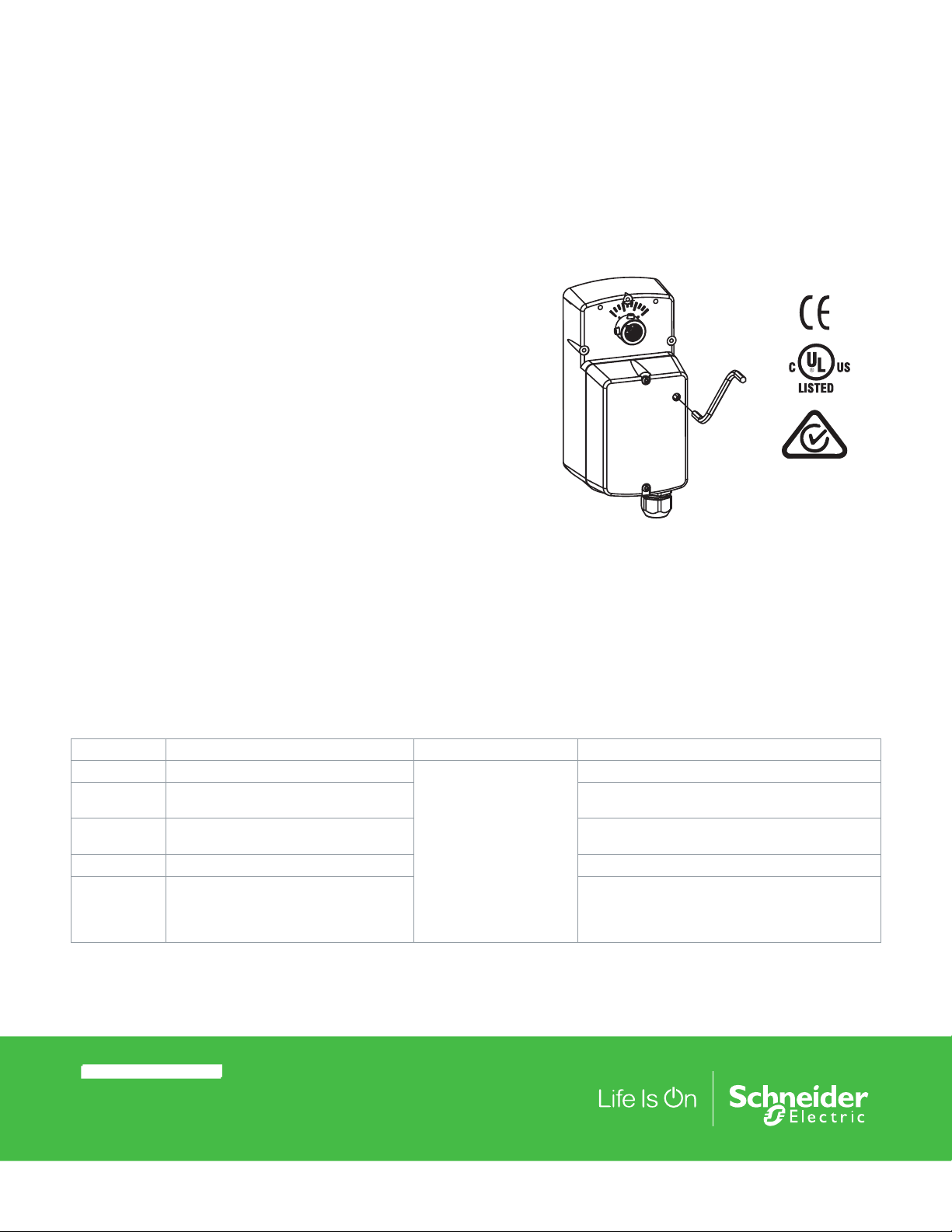
Installation Instructions
MA/F/S 4D-xxxx-xxx Two Position,
Floating and Proportional Series
SmartX Actuators Rotary Overshaft Actuators
Application
Rotary overshaft SmartX Actuators provide an economical and
reliable solution for many overshaft damper and Schneider
Electric VB2000 ball valve requirements. All products accommodate shaft sizes up to 1/2” (13 mm) in diameter.
Spring return models provide 30 in-lb (3.4 N-m) of torque in
either two position, floating or proportional control. Non-spring
return models provide either 35 in-lb (4 N-m) or 70 in-lb (8 N-m)
in either floating or proportional control.
Features
• Two position models controlled by SPST controller
• Floating models controlled by SPDT floating controllers
• Proportional models controlled by 0 to 3 Vdc, 6 to 9 Vdc, 0
to 10 Vdc, 2 to 10 Vdc or 4 to 20 mAdc with the addition of
a 500 ohm resistor. Control function direct/reverse action is
jumper selectable
• Spring return models provide 30 in-lb (3.4 N-m) of torque
• Non-spring return models supply 35 in-lb (4 N-m) or 70 in-lb
(8 N-m) of torque
• Polymer housing rated for NEMA 2/IP54
F-Number Description Audience Purpose
F-25097 Accessory AM-714 General Instructions
F-26080 EN-205 Water System Guidelines Describes Schneider Electric approved water treat-
F-26895 Accessories AM-703, AM-704, AM-705,
AM-706, AM-708 General Instructions
F-26899 Accessory AM-756 General Instructions
F-27086 Vx-2x13-5xx-9-xx Series, VB-2x13-500-9-
xx Series Schneider Electric VB2000 Ball
Valve Assemblies Ball Valve Body/LInkage
Selection Guide
– Sales Personnel
– Application Engineers
– Installers
– Service Personnel
– Start-up Technicians
MA4D-xxxx
• Overload protection throughout stroke
• Floating and proportional models automatically adjust the
input span to match the damper/valve travel
• Compact size to allow installation in limited space
• Manual override to allow positioning of dampers and valves
• Directly mounts to 1/2 to 3” Schneider Electric VB2000 ball
valves
• Polymer housing rated for plenum use
Provides step-by-step installation procedures.
ment practices.
Provides step-by-step installation procedures.
Provides features, specifications, mounting dimensions, and other criteria useful in the selection of
ball valve assemblies.
Note: All performance specifications are nominal and conform to acceptable industry standards. For applications at conditions
beyond these specifications, consult Schneider Electric. Schneider Electric shall not be liable for damages resulting from misapplication or misuse of its products.
© 2018 Schneider Electr ic. All right s reserve d. All tradem arks are owne d by Schneider Electric Ind ustries SA S or its aff iliated compa nies. Novemb er, 2018 tc
Docume nt Number: F-2 7170-7
Page 2
Installation Instructions
Specifi
Actuator Inputs
Control Signal
Power Input
Connections
Actuator Outputs
Electrical
Position Feedback Voltage
(proportional or floating only)
Mechanical
Timing
Travel
Manual Override
cations
See Table-1 thru 4 for actuator mod-
els and control types.
See Table-1 thru 4. All 24 Vac circuits
are Class 2. All circuits 30 Vac and
above are Class 1.
3 ft (91 cm) appliance or plenum ca-
bles, enclosure accepts 1/2” (13 mm)
conduit connector. For M20 Metric
conduit, use AM-756 adaptor.
For voltage ranges, the feedback
signal is the same range as the input
signal. The 4 to 20 mA current range
and floating actuators have a 2 to 10
Vdc feedback signal. The feedback
signal can supply up to 0.5 mA to
operate up to four additional slave
actuators.
See Figure-1 to Figure-4.
93° nominal.
Allows positioning of damper or valve
using manual crank.
Environment
Ambient Temperature Limits
Shipping & Storage
Operating
Humidity
Location
Agency Listings
UL 873
CUL
European Community
Australia
-40 to 160°F (-40 to 71°C).
-22 to 140°F (-30 to 60°C).
15 to 95% RH, non-condensing.
NEMA 1. NEMA 2, UL Type 2 (IEC
IP54) with customer supplied water
tight conduit connectors. Enclosure is
air plenum rated.
Underwriters Laboratories (File
#E9429 Category Temperature-Indi-
cating and Regulating Equipment).
UL Listed for use in Canada by
Underwriters Laboratories. Canadian
Standards C22.2 No. 24-93.
EMC Directive (89/336/EEC). Low
Voltage Directive (72/23/EEC). This
product fits in Installation Category
(Overvoltage Category) II per EN
61010-1.
This product meets requirements to
bear the RCM according to the terms
specified by the Communications
Authority under the Radiocommuni-
cations Act 1992.
RA/DA Jumper
Table 1. 30 in-lb (3.4 N-m) Spring Return CCW Actuators (Viewed from cover side)
Part Number Control Signal Voltage Wiring System
MA4D-7033-000
MA4D-7033-100 Plenum Cable
2
MA4D-7030-000
MA4D-7031-000
MF4D-7033-000
MF4D-7033-100 Plenum Cable
MS4D-7033-000
MS4D-7033-100 Plenum Cable
MS4D-7033-020
MS4D-7033-120 Plenum Cable
MS4D-7033-030
MS4D-7033-130 Plenum Cable
MS4D-7033-050
MS4D-7033-150 Plenum Cable
MS4D-7033-060
MS4D-7033-160 Plenum Cable
a Timing was measured with no load applied to actuator.
b 4 to 20 mAdc with field-installed 500 ohm resistor.
Position
SPST
Floating
2 to 10 Vdcb
Proportional
0 to 3 Vdc
Proportional
6 to 9 Vdc
Proportional
0 to 10 Vdc
Proportional
4 to 20 mAdc
Proportional
Permits reverse acting/direct acting
control (MS4D models only).
24 VAC
+/-20%
or 20-30
Vdc
120 Vac ±
10%
50/60 Hz
230 Va ±
10%
50/60 Hz
24 Vac
+/-20%
or 20-30
Vdc
Appliance Wire
Appliance Wire
Appliance Wire
Appliance Wire
Appliance Wire
Appliance Wire
Appliance Wire
Appliance Wire
50/60 Hz
VA W W
5.1 3.6 0.14 1.3
7.8 5.0 — 2.5
7.2 5.2 — 2.4
6.8 4.2 0.15 1.9
6.1 3.4 0.12 1.4
Actuator Power Input
Running Holding
DC
Amps
50/60 Hz
Approximate Timinga in
Sec. @ 70 °F (21 °C)
Pow-
ered
56 23
85 21
Spring Return
(CCW)
November, 2018 tc © 2018 Schneider Electr ic. All right s reserve d. All tradem arks are owne d by Schneider Electric Ind ustries SA S or its aff iliated compa nies.
Document Number: F-27170-7
Page 3
Installation Instructions
Table 2. 30 in-lb (3.4 N-m) Spring Return CW Actuators (Viewed from cover side)
Part Number
Control
Signal
Voltage Wiring System
50/60 Hz
VA W W
MA4D-8033-000
MA4D-8033-100 Plenum Cable
MA4D-8030-000
2
Position
SPST
MA4D-8031-000
MF4D-8033-000
MF4D-8033-100 Plenum Cable
MS4D-8033-000
MS4D-8033-100 Plenum Cable
MS4D-8033-020
MS4D-8033-120 Plenum Cable
MS4D-8033-030
MS4D-8033-130 Plenum Cable
MS4D-8033-050
MS4D-8033-150 Plenum Cable
MS4D-8033-060
MS4D-8033-160 Plenum Cable
a Timing was measured with no load applied to actuator.
b 4 to 20 mAdc with field-installed 500 ohm resistor.
Floating
2 to 10 Vdcb
Proportional
0 to 3 Vdc
Proportional
6 to 9 Vdc
Proportional
0 to 10 Vdc
Proportional
4 to 20 mAdc
Proportional
24 VAC +/-20%
or 20-30 Vdc
120 Vac ± 10%
50/60 Hz
230 Va ± 10%
50/60 Hz
24 Vac +/-20%
or 20-30 Vdc
Appliance Wire
Appliance Wire
Appliance Wire
Appliance Wire
Appliance Wire
Appliance Wire
Appliance Wire
Appliance Wire
5.1 3.6 0.14 1.3
7.8 5.0 — 2.5
7.2 5.2 — 2.4
6.8 4.2 0.15 1.9
6.1 3.4 0.12 1.4
Actuator Power Input Approximate Timing
Running Holding
DC
50/60
Hz
Amps
in Sec. @ 70 °F (21
°C)
Pow-
ered
Spring Re-
turn (CW)
56 23
85 21
a
Table 3. Non-Spring Return 35 in-lb (4 N-m) Actuators.
Part Number
MF4D-6043-000
MF4D-6043-100 Plenum Cable
MS4D-6043-000
MS4D-6043-100 Plenum Cable
MS4D-6043-020
MS4D-6043-120 Plenum Cable
MS4D-6043-030
MS4D-6043-130 Plenum Cable
MS4D-6043-050
MS4D-6043-150 Plenum Cable
MS4D-6043-060
MS4D-6043-160 Plenum Cable
a Timing was measured with no load applied to actuator.
b 4 to 20 mAdc with field-installed 500 ohm resistor.
Control
Signal
Floating
2 to 10 Vdcb
Proportional
0 to 3 Vdc
Proportional
6 to 9 Vdc
Proportional
0 to 10 Vdc
Proportional
4 to 20 mAdc
Proportional
Voltage Wiring System
Appliance Wire
Appliance Wire
Appliance Wire
24 Vac +/-20%
or 20-30 Vdc
Appliance Wire
Appliance Wire
Appliance Wire
Actuator Power Input
Running Holding
50/60 Hz
VA W W
DC
Amps
4.4 2.7 0.1 1.7
4.2 2.2 0.08 1.2
50/60
Hz
Approximate Timinga
in Sec. @ 70 °F (21
°C)
85
© 2018 Schneider Electr ic. All right s reserve d. All tradem arks are owne d by Schneider Electric Ind ustries SA S or its aff iliated compa nies. Novemb er, 2018 tc
Docume nt Number: F-2 7170-7
Page 4
Installation Instructions
Table 4. Non-Spring Return 70 in-lb (8 N-m) Actuators.
Part Number
MF4D-6083-000
MF4D-6083-100 Plenum Cable
MS4D-6083-000
MS4D-6083-100 Plenum Cable
MS4D-6083-020
MS4D-6083-120 Plenum Cable
MS4D-6083-030
MS4D-6083-130 Plenum Cable
MS4D-6083-050
MS4D-6083-150 Plenum Cable
MS4D-6083-060
MS4D-6083-160 Plenum Cable
a Timing was measured with no load applied to actuator.
b 4 to 20 mAdc with field-installed 500 ohm resistor.
Control
Signal
Floating
2 to 10 Vdcb
Proportional
0 to 3 Vdc
Proportional
6 to 9 Vdc
Proportional
0 to 10 Vdc
Proportional
4 to 20 mAdc
Proportional
Voltage Wiring System
Appliance Wire
Appliance Wire
Appliance Wire
24 Vac +/-20%
or 20-30 Vdc
Appliance Wire
Appliance Wire
Appliance Wire
Actuator Power Input
Running Holding
50/60 Hz
VA W W
5.9 3.6 0.13 1.6
5.2 2.7 0.10 1.4
DC
Amps
50/60
Hz
Approximate Timing
in Sec. @ 70 °F (21
°C)
85
a
Ball Valve Close-Off Pressures: For close-off pressure ratings on Schneider Electric VB2000 ball valves, consult Schneider Electric VB2000 Ball Valve Assemblies Ball Valve Body/Linkage Selection Guide F-27086.
Accessories
AM-763 1/8” Hexcrank for manual override
AM-756 Metric Conduit Adapter M20 x 1.5 to 1/2” NPT
AM-771 Crank Arm and bracket kit
AM-772 Bracket for reverse mounting
AM-714 Weathershield Kit
MS4D-xxx3-xxx
AM-703 Input rescaling module, adjust signals to 2-10 Vac, zero and span adjust
AM-704 Interface, pulse width modulation (PWM)
AM-705 Positioner (NEMA 4 housing)
AM-706 Min and/or manual positioner for flush panel mount
AM-708 500 Ω resistor for 4 to 20 mA control signal
November, 2018 tc © 2018 Schneider Electr ic. All right s reserve d. All tradem arks are owne d by Schneider Electric Ind ustries SA S or its aff iliated compa nies.
Document Number: F-27170-7
Page 5
120 Vac or
Volts
(+)
Installation Instructions
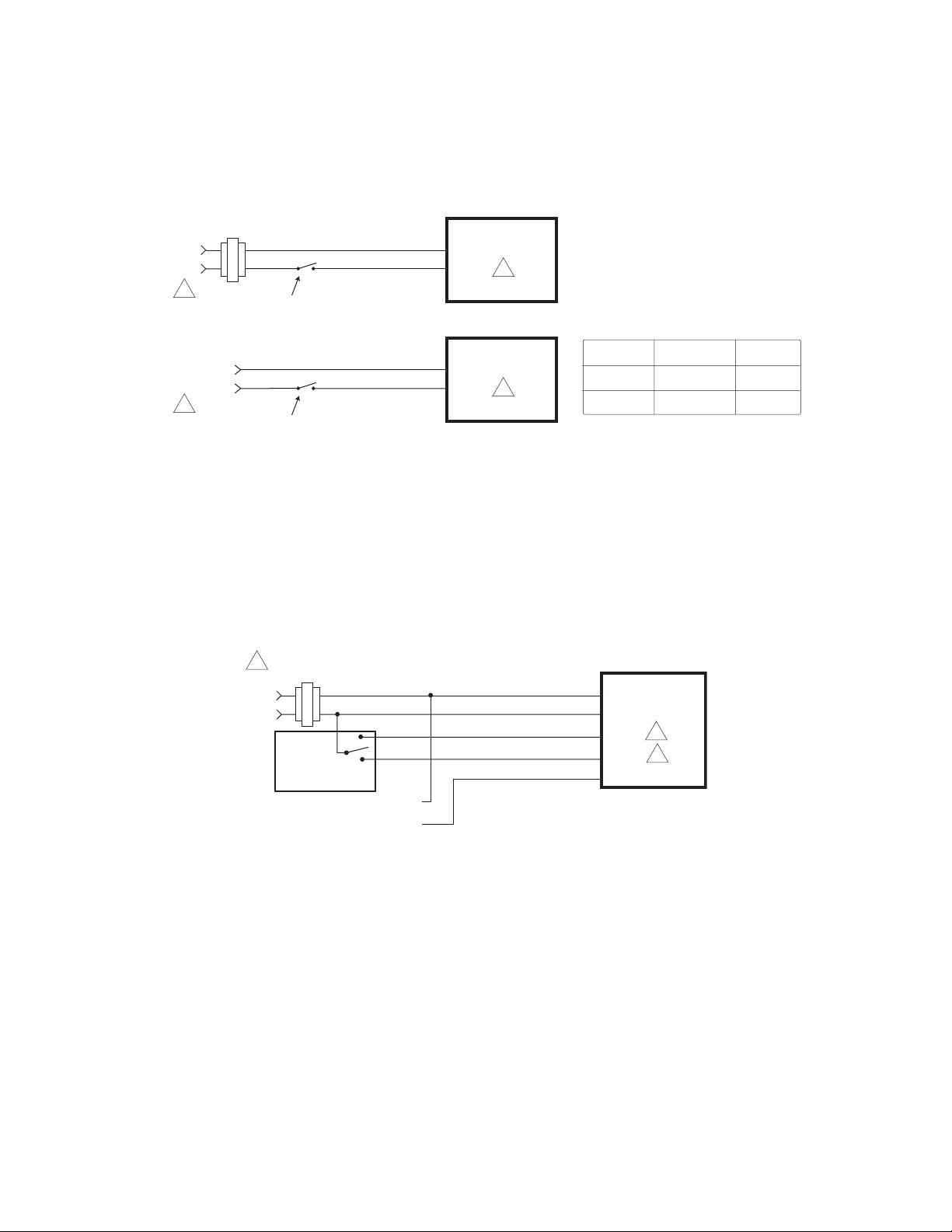
Typical Two Position Control (Wiring Diagrams)
Figure-1 illustrates typical wiring diagrams for spring return twoposition MA4D-x03x-xxx SmartX Actuators. See Tables1-2 for model selection.
24 Vac Transformer
or 22-30 Vdc
Line
Volts
1
Blk
Red
SPST Control Contact
Hot (+DC)
Com
MA4D-X033-X00
2
Voltage L1 N L2 Hot
120 Vac White Black
230 Vac Blue Brown
230 Vac
1
L1
L2
SPST Control Contact
Hot
MA4D-X033-X00
N
2
Figure-1 Typical Wiring Diagrams for Two Position SmartX Actuators.
Typical Floating Control (Wiring Diagrams)
Figure-2 through Figure-5 illustrate typical wiring diagrams for floating MF4D-xxx3-x00 actuators. See Tables 1-4 for
model selection.
Caution: This product contains a half-wave rectifier power supply and must not be powered off transformers used to
power other devices utilizing non-isolated full-wave rectifier power supplies. Refer to EN-206, Guidelines for Power Multiple Devices from a Common Transformer, F-26363 for detailed information.
24 Vac Transformer
1
or 20-30 Vdc
Line
Typical
Floating
Controller
Feedback Signal
2 to 10 Vdc
Black
Red
Blue
(-)
Common
Hot (+DC)
Drive Open
Drive Closed Yellow/Black
Violet
MF4D-XXX3-X00
2
7
Figure-2 Floating Point Control.
© 2018 Schneider Electr ic. All right s reserve d. All tradem arks are owne d by Schneider Electric Ind ustries SA S or its aff iliated compa nies. Novemb er, 2018 tc
Docume nt Number: F-2 7170-7
Page 6

24 Vac Transformer
1
Volts
Volts
24 Vac Transformer
24 Vac Transformer
Volts
Line
Installation Instructions
or 20-30 Vdc
1
Line
Hot
Controller
or 20-30 Vdc
Hot
Controller
Common
Feedback Signal
2 to 10 Vdc
Common
Feedback Signal
2 to 10 Vdc
Black
Red
Blue
Yellow/Black
Drive Closed
(-)
(+)
Figure-3 Triac source.
Black
Red
Blue
Yellow/Black
Violet
(-)
(+)
Common
Hot (+DC)
Drive Open
Violet
Common
Hot (+DC)
Drive Open
Drive Closed
MF4D-XXX3-X00
2 7
MF4D-XXX3-X00
2
AO
4 7
3
November, 2018 tc © 2018 Schneider Electr ic. All right s reserve d. All tradem arks are owne d by Schneider Electric Ind ustries SA S or its aff iliated compa nies.
24 Vac Transformer
1
or 20-30 Vdc
Line
Hot
Controller
Figure-4 Triac Sink.
1
or 20-30 Vdc
Line
Volts
Common
Yellow/Black
Feedback Signal
2 to 10 Vdc
Black
Red
Blue
(-)
(+)
Common
Hot (+DC)
Drive Open
Drive Closed
Violet
AO
Figure-5 Triac Sink With Separate Transformers.
MF4D-XXX3-X00
2
3
4 7
Document Number: F-27170-7
Page 7

Feedback Signal
Actuators
Feedback Signal
Installation Instructions
Typical Proportional Control (Wiring Diagrams)
Figure-6 illustrates typical wiring diagrams for proportional MS4D-xxx3-xx0 actuators. See Table-1 for model selection.
Caution: This product contains a half-wave rectifier power supply and must not be powered off transformers used to power other
devices utilizing non-isolated full-wave rectifier power supplies. Refer to EN-206, Guidelines for Powering Multiple Devices from a
Common Transformer, F-26363 for detailed information.
24 Vac Transformer
1
Line
Volts
Vdc or mAdc
Control Signal
Vdc
or 20-30 Vdc
(-)
(+)
(-)
(+)
Vdc Proportional Control
Blk
Com
Red
Hot (+DC)
Yel/Blk
Violet AO
MS4D-XXX3-XX0
AI
2
6 7
24 Vac Transformer
1
Line
Volts
4
Control Signal
4 to 20 mAdc
Feedback Signal
4
2 to 10 Vdc
4 to 20 mAdc Proportional Control
or 20- 30 Vdc
(-)
(+)
(-)
500 Ω
Blk
5
Yel/Blk
Violet
(+)
To Additional
2
Com
Hot (+DC)Red
AI
AO
Figure-6 Typical Wiring Diagrams for Proportional Control 24 Vac Basic Models.
24 Vac Transformer
1
or 20- 30 Vdc
Line
Volts
Control Signal
2 to 10 Vdc
2 to 10 Vdc
(-)
(+)
(-)
(+)
Blk
Red
Yel/Blk
Violet
Blk
Red
Yel/Blk
Violet
Com
Hot (+DC)
AI
AO
Com
Hot (+DC)
AI
AO
MS4D-XXX3-XX0
2 3
7
MS4D-XXX3-XX0
2 3
7
MS4D-XXX3-X00
2
4
7
© 2018 Schneider Electr ic. All right s reserve d. All tradem arks are owne d by Schneider Electric Ind ustries SA S or its aff iliated compa nies. Novemb er, 2018 tc
Docume nt Number: F-2 7170-7
Figure-7 Typical Wiring Diagrams for Proportional Control 24 Vac Models
Wired in Parallel.
1 Provide overload protection and disconnect as
required.
2 Actuators may be wired in parallel. All actuator black
wires are connected to the transformer common and
all red wires are connected to the hot lead. Power
consumption must be observed.
3 The Common connection from the actuator must be
connected to the Hot connection of the controller. The
actuator Hot must be connected to the controller
Common.
4 If the controller uses a full-wave power supply and
does not provide isolated outputs, a separate
transformer is required.
5 A field-supplied 500 ohm resistor (AM-708) is
required for this application.
6 On MS4D-XXX3-X60 (0-20 mAdc) models a
500 resistor is incorporated in the product. Do
not use an external resistor.
7 Cable on some models contains more wires
than are used in applications. Only those
wires actually used are shown.
Figure-8 Triangle Notes for Wiring Diagrams.
Page 8

Installation Instructions
Installation
Inspect the package for damage. If damaged, notify the appropriate carrier immediately. If undamaged, open the package and
inspect the device for obvious damage. Return damaged products.
Requirements
• Job wiring diagrams
• Appropriate accessories
• Installer must be a qualified, experienced technician
• 1/8” hex allen wrench (not provided)
• #8 Torx screwdriver (not provided)
• #8 sheet metal screws (2) (not provided)
• Appropriate drill bits (not provided
Precautions
Warning:
• Electrical shock hazard! Disconnect the power supply (line power) before installation to prevent electric shock and equipment
damage.
• Make all connections in accordance with the job wiring diagram and in accordance with national and local electrical codes.
Use copper conductors only.
• Floating and Proportional Models: These products contain a half-wave rectifier power supply. They must not be powered with
transformers that are used to power other devices utilizing non-isolated full-wave rectifier power supplies. Refer to EN-206,
Guidelines For Powering Devices From A Common Transformer, F-26363 for detailedinformation.
Caution:
• Avoid electrical noise interference. Do not install near large contactors, electrical machinery, or welding equipment.
• Manual override to be used only when power is not applied to unit.
• When operating manual override (observe position indicator), back off 5° from full extended mechanical stop to ensure proper
release.
Federal Communications Commission (FCC)
Note: This equipment has been tested and found to comply with the limits for a Class B digital device, pursuant to Part 15 of the
FCC Rules. These limits are designed to provide reasonable protection against harmful interference in residential installations.
This equipment generates, uses, and can radiate radio frequency energy and may cause harmful interference if not installed and
used in accordance with the instructions. Even when instructions are followed, there is no guarantee that interference will not
occur in a particular setting—Which can be determined by turning the equipment off and on—the user is encouraged to try to
correct the interference by one or more of the following measures:
• Reorient or relocate the receiving antenna.
• Increase the separation between the equipment and receiver.
• Connect the equipment to an outlet on a circuit different from that to which the receiver is connected.
• Consult the dealer or an experienced radio/television technician for help.
Canadian Department of Communications (DOC)
Note: This Class B digital apparatus meets all requirements of the Canadian Interference- Causing Equipment Regulations.
Cet appareil numerique de la classe B respecte toutes les exigences du Reglement sur le material broilleur du Canada.
European Standard EN 55022
Note: This is a Class B digital (European Classification) product. In a domestic environment this product may cause radio interference in which case the user may be required to take adequate measures.
Location
Caution: Avoid locations where excessive moisture, corrosive fumes, vibration, or explosive vapors are present.
November, 2018 tc © 2018 Schneider Electr ic. All right s reserve d. All tradem arks are owne d by Schneider Electric Ind ustries SA S or its aff iliated compa nies.
Document Number: F-27170-7
Page 9

Installation Instructions
Mounting
Changing Control Function (proportional units only)
These actuators are equipped with a jumper to control the function of the signal as received. See Figure-9. Factory setting is for direct
acting (actuator moves away from normal position as signal increases). Remove cover to change jumper settings.
Direct Acting
(pins connected)
Reverse Acting
(pins open)
Note: Cover screws are #8 Torx.
Figure-9 RA/DA Jumper Setting for Proportional Models.
Figure-10 Location of Manual Override.
© 2018 Schneider Electr ic. All right s reserve d. All tradem arks are owne d by Schneider Electric Ind ustries SA S or its aff iliated compa nies. Novemb er, 2018 tc
Docume nt Number: F-2 7170-7
Page 10

)
Move the damper to its normal position. Verify the controller action is set to match the
damper application.
Installation Instructions
Manual Override Operation
When necessary, the actuator’s output shaft can be repositioned using the manual override mechanism (Figure-10) as follows:
1. Disconnect power from the actuator. Spring return models will fully return to their normal position. Non-spring return
models will remain in position.
2. Insert the crank in the product. Without pushing in on the crank, rotate the manual override crank in the direction shown
by the arrow on the product label until the actuator rotates to the desired position. Push in until the mechanism locks in
position. Non-spring return models do not have the locking feature.
3. If you desire to reposition a spring return actuator manually from a locked position, turn crank 1/8 turn counterclockwise
and pull out to release. Adjust position as desired.
4. If you desire to reposition a non-spring return actuator manually, turn the crank in either direction as needed until you
reach the desired position.
Caution:
• Only use manual override when the actuator drive motor is not powered.
• Engaging the manual override when the actuator is powered will cause damage to the gears.
• Using power tools to adjust the override will cause damage to the gears.
• Avoid manually repositioning the actuator beyond its adjustable travel limit setting.
Damper Mounting
Mx4D-xxxx-xxx SmartX Actuator Rotary Damper
Installation
Caution: Do not drill additional holes in the actuator body. Pre-drilled holes are located on gear plate side to accept #8-32
thread-forming screws for mounting accessories.
Note: The Mx4D-xxxx-xxx rotary actuators mount on shafts up to 1/2” diameter. Two set screws secure the actuator to the
shaft.
Spring return models can be mounted from top or bottom. When mounting from the
top, use AM-772 bracket. See Figure-12.
Normally closed damper: when damper is closed, actuator position indicator should
be at 0°. When damper is open, actuator position indicator should be at 90°.
Normally opened damper: when damper is open, actuator position indicator should
be at 0°. When damper is closed, actuator position indicator should be at 90°.
This step determines
shaft rotation. Linkage
may change damper direction.
Min. 2-3/8" (60 mm
Shaft Rotates
Clockwise
To Open
Shaft Rotates
Counterclockwise
To Open
Figure-11 Rotary Damper Position.
November, 2018 tc © 2018 Schneider Electr ic. All right s reserve d. All tradem arks are owne d by Schneider Electric Ind ustries SA S or its aff iliated compa nies.
Document Number: F-27170-7
Page 11

Clockwise to open
unter clockwise to open
Installation Instructions
C
L
Centerline
6
Co
C
L
Centerline
7216
MX4D-6XXX
MX4D-7XXX
45
#8 sheet metal screws
(not provided)
MX4D-6XXX
MX4D-8XXX
3
1/2
1/2
Reverse mounting
using bracket
provided
AM-772
Figure-12 Shaft Installation.
Crankarm Kit
AM-771
1. Slide actuator over damper shaft.
2. To set a damper preload of 5°, use manual crank to position the actuator 2 full turns from the desired damper
closed position. On spring return models, lock the crank in position. See Manual Override Operation, page 10.
3. Hand tighten clamping set screws using 1/8” hex wrench.
4. Center the anti-rotation bracket in the slot and drill holes for two mounting screws.
5. Insert anti-rotation bracket mounting screws and tighten.
6. Tighten the two shaft set screws evenly to 50 to 60 in-lb (5.7 to 6.8 Nm) using a 1/8” hex wrench.
© 2018 Schneider Electr ic. All right s reserve d. All tradem arks are owne d by Schneider Electric Ind ustries SA S or its aff iliated compa nies. Novemb er, 2018 tc
Docume nt Number: F-2 7170-7
Page 12

Installation Instructions
Ball Valve Mounting
Installation of Mx4D-xxxx-xxx Actuators on 1/2” to 3” Schneider Electric VB2000 Ball Valves
Install the actuator onto the ball valve according to Figure-16.
Note: If space constraints do not allow the actuator to be installed in the standard position, reposition the mounting plate
before mounting the actuator.
The valve should be mounted in a weather-protected area, in a location that is within the ambient temperature limits of the
actuator. The installation of the actuator assembly should provide clearance on all sides to allow for any maintenance that
may be needed (see Figure-13 thru Figure-15).
1. Follow the general piping practices.
2. Apply pipe sealant sparingly to all but the last two threads of a properly threaded, reamed, and cleaned pipe. Make sure
the pipe chips, scale, etc. do not get into the pipe since this material may lodge in the valve seat and prevent proper
operation of the valve. The valve must be piped with an inlet and an outlet.
3. Start the joint hand-threading the pipe into the valve. If the thread alignment feels normal, continue to turn the pipe by
hand as far as it will go.
4. Use a pipe wrench to fully tighten the pipe to the valve.
5. Caution: Do not over-tighten the pipe, which may cause stripped threads. Avoid twisting or crushing the valve while tight-
ening the pipe.
6. Insulate only the valve body and associated piping. Do not insulate the actuator.
7. In chilled or cold water systems where the environment is humid, use a drip pan under the valve to catch condensate.
Caution: The Schneider Electric SmartX Actuator is designed to effectively support its own weight. No load or weight should
be resting on the actuator. Long term damage may occur to the actuator, mounting connection, or valve.
• Do not insulate the actuator/linkage. Doing so will result in excess heat buildup within the actuator.
• For non-steam applications the ball valve assembly must be mounted so the actuator is at least 5° above horizontal
(Figure-13) to ensure that any condensate that forms will not travel into the mounting bracket or actuator.
• On steam applications, the ball valve assembly must be mounted approximately 45° from horizontal (Figure-14).
• Temperature Restrictions: To maintain the maximum ambient temperature 140 °F (60 °C) of the actuator/valve, the
maximum allowable fluid temperature should not exceed the 250 °F(121 °C) ball valve maximum rating.
85˚
Max
0˚
3-7/8" (99 mm) Min.
Clearance
85˚
Max
Figure-13 Acceptable Mounting Orientations.
November, 2018 tc © 2018 Schneider Electr ic. All right s reserve d. All tradem arks are owne d by Schneider Electric Ind ustries SA S or its aff iliated compa nies.
Document Number: F-27170-7
Page 13

0˚0˚
180˚
90˚
Installation Instructions
0˚
45˚
45˚
Figure-14 Mounting Orientations for Steam Applications.
90˚
180˚
Figure-15 Unacceptable Mounting Orientation.
© 2018 Schneider Electr ic. All right s reserve d. All tradem arks are owne d by Schneider Electric Ind ustries SA S or its aff iliated compa nies. Novemb er, 2018 tc
Docume nt Number: F-2 7170-7
Page 14

Index Mark on
=
Top of Shaft
Installation Instructions
3-Way Mixing
AB
AB
Inlet
Closed
(Fully CW)
Outlet
2-Way
Inlet
Open
Outlet
A
B Full Open to
(Fully CW)
1
5
2
6
3
4
Figure-16 Installation of Mx4D-xxxx-xxx SmartX Actuator.
AB
A
A Full Open to AB
Installation
For Normally Open 2-Way and Normally Open A to AB 3-Way (Mx4D-7xxx)
1. Verify that the valve is in the open position (A to AB open on 3-way valves). This position of the ball opening is indicated by
the index mark on top of the shaft.
For Normally Closed 2-Way and Normally Closed A to AB 3-Way (Mx4D-8xxx)
1. Verify that the valve is in the closed position (A to AB closed on 3-way valves). The position of the ball opening is indicated by
the index mark on top of the shaft.
For Non-Spring Return 2-Way and 3-Way (Mx4D-8xxx)
1. Verify that the valve is in the closed position (A to AB closed on 3-way valves). The position of the ball opening is indicated by
the index mark on top of the shaft.
2. Align the actuator with the mounting plate, then slide the anti-rotation clip half-way into the slot on the bottom of the actuatoR.
3. Tighten the wing nut to secure the anti-rotation clip in place. Be careful not to overtighten the wing nut.
4. Using a 1/8” hex wrench, evenly tighten the two setscrews to 50 to 60 in-lb (5.7 Nm to 6.8 Nm).
To reposition Base:
1. With actuator removed, remove screws.
2. Lift mounting plate while holding valve stem in position.
3. Rotate base in 45 degree increments.
4. Replace screws after reseating base in position.
November, 2018 tc © 2018 Schneider Electr ic. All right s reserve d. All tradem arks are owne d by Schneider Electric Ind ustries SA S or its aff iliated compa nies.
Document Number: F-27170-7
Page 15

Installation Instructions
Wiring
Requirements
Control Leads
See Table-5 for power wiring data. Refer to Figure-1 through Figure-8 for typical wiring.
Table-5 Power Wiring.
SmartX
Actuator
Voltage
24 Vac and
22-30 Vdc
Part Number
MA4D-7033
MA4D-8033
MF4D-7033
MF4D-8033
MS4D-7033
MS4D-8033
MF4D-6083
MS4D-6083
MF4D-6043
MS4D-6043
12 AWG 14 AWG 16 AWG 18 AWG 20 AWG 22 AWG
1744
(532)
1308
(399)
1458
(444)
1508
(459)
1710
(521)
2021
(616)
2118
(645)
Maximum Wire Run in ft. (m)
1097
(534)
822
(251))
917
(279)
948
(289)
1075
(328)
1271
(387)
1331
(406)
690
(210)
517
(158)
577
(276)
596
(182)
676
(206)
799
(244)
837
(255)
434
(132)
325
(99)
325
(99)
375
(114)
425
(130)
503
(153)
527
(161)
273
(83)
205
(62))
228
(70)
236
(72)
268
(82)
268
(82)
331
(101)
216
(66)
162
(49)
181
(55)
187
(57)
212
(65)
251
(76)
263
(80)
Checkout
With the correct control signals applied, power the actuator. Observe movement of the output shaft to check for proper operation. If a spring return model, removing power should cause the actuator to spring return to its rest position. If problems are
encountered, check the suggestions below.
Note: Check that the transformer(s) are sized properly.
• If a common transformer is used with multiple actuators, make sure that polarity is observed on the secondary. This means
connecting all black wires to one leg of the transformer and all red wires to the other leg of the transformer.
• If multiple transformers are used with one control signal, make sure all black wires are tied together and tied to control
signal negative (-).
• If the controller uses a full-wave power supply and does not provide isolated outputs, a separate transformer is required to
power the actuator.
© 2018 Schneider Electr ic. All right s reserve d. All tradem arks are owne d by Schneider Electric Ind ustries SA S or its aff iliated compa nies. Novemb er, 2018 tc
Docume nt Number: F-2 7170-7
Page 16

1-1/8 ( 29 mm)
Installation Instructions
Theory Of Operation
The MA series SmartX Actuators provide two position spring return operation. They are equipped with a mechanical spring return
mechanism. When power is applied, the actuator moves to its powered position, at the same time tensing the spring return safety
mechanism. When power is removed, the spring returns the actuator to its normal position (retracted). The spring return system
provides consistent close-off for sensitive damper or valve applications.
MA series two position actuators use a brush DC motor controlled by on-board electronics. When the actuator encounters a stall
or end of travel position, the motor current is automatically reduced, preventing damage to the actuator or motor.
MF or MS series floating or proportional SmartX Actuators use a brush DC motor which is controlled by a microprocessor. The microprocessor supplies the intelligence to provide a constant speed and to know the actuators exact position. The microprocessor
monitors and controls the DC motors rotation and provides a digital rotation sensing function to prevent damage to the actuator in
a stall condition.
All actuators may be stalled anywhere in their normal rotation without the need of mechanical end switches.
Maintenance
Regular maintenance of the total system is recommended to assure sustained optimum performance. The Linear series actuators
are maintenance free.
Field Repair
None. Replace with functional actuator.
Dimensional Data
3-1/2 (89 mm)
3-1/2 (89 mm)
Note: -1XX models only
6-3/4 (172 mm)
Figure-17 Mx4D-xxxx-xxx Spring Return Valve Actuator
Dimensions.
November, 2018 tc © 2018 Schneider Electr ic. All right s reserve d. All tradem arks are owne d by Schneider Electric Ind ustries SA S or its aff iliated compa nies.
Document Number: F-27170-7
 Loading...