


TAC I/A Series
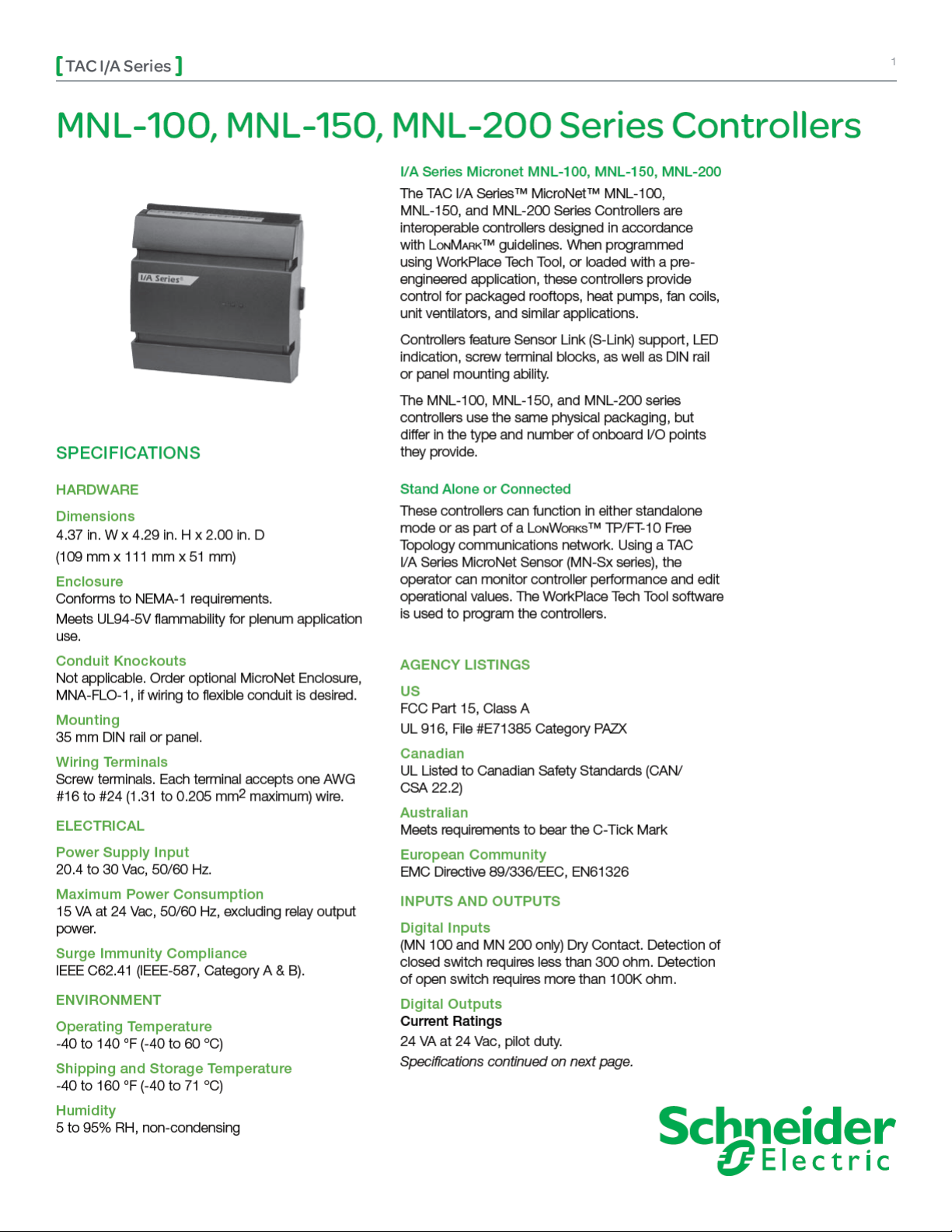
MNL-100, MNL-150, and MNL-200 Series Controllers
2
Specifications continued from first page.
Universal Inputs
1K ohm Balco Input
-40 to 250 °F (-40 to 121°C) range. TSMN-81011,
TS-8000 Series or equivalent.
1K ohm Platinum Input
-40 to 240 °F (-40 to 116 °C) range. TSMN-58011,
TS-5800 Series or equivalent.
1k Resistance
0 to 1.5k ohms.
10K ohm Thermistor w/ 11K ohm Shunt Resistor
-40 to 250 °F (-40 to 121 °C) range. TSMN-57011850, TS-5700-850 Series or equivalent.
10k Resistance
0 to 10.5k ohms.
Voltage
0 to 5 Vdc.
Current
0 to 20 mA requires an external 250 ohm shunt
resistor.
Digital Input
Dry Contact. Detection of closed switch requires less
than 300 ohms. Detection of open switch requires
more than 1.5K ohms.
Analog Outputs
(MN 150 and MN 200 only).
Current
0 to 20 mA. (Output load from 80 to 550 ohms).
FEATURES
Designed for new or existing system installations, •
the MN 100, 150, and 200 controllers provide
control for: unit ventilators; series fan; heat
pumps; fan coils; and packaged rooftops.
Conforms to the • L
HVAC interoperability achieved through use of •
o n Ma r k HVAC profiles.
L
A complete, custom application can be designed •
for each controller, using WorkPlace Tech Tool.
All controllers are field programmable, using •
WorkPlace Tech Tool, but controllers with satellite
profiles are especially suited for a broad range of
applications, providing solutions for your building
control needs.
Capability to function in standalone mode or •
as part of a Lo n Wo r k s TP/FT-10 Free Topology
communications network.
Multiple controllers on a • L
creates a complex network of controllers for
virtually any building control need.
Proportional (P), Proportional Plus Integral (PI), •
and Proportional Plus Integral and Derivative (PID)
control for cooling and heating.
Onboard LED indication without cover removal.•
Plenum-rated enclosure allows direct mounting in •
plenum.
Protective hinged covers provide access to field •
wiring terminals.
o n Ma r k guidelines.
o n Wo r k s FTT network
COMMUNICATIONS
Lo n Wo r k s Networks
A L
o n Wo r k s communications network uses a
TP/FT-10 Free Topology configuration. Controllers
on a L
o n Wo r k s network can communicate with each
other in a peer-to-peer fashion. A L
has a communications speed of 78 kbps, using
unshielded, twisted-pair cabling, with connections
that are not polarity sensitive.
S-Link
The Sensor Link (S-Link) communications wiring
provides power and a communication interface for an
MN-Sx MicroNet sensor. The various MN-Sx sensors
can provide room temperature, room humidity,
setpoint adjustment, and occupancy override. This
connection uses two-wire, unshielded cable and is
not polarity sensitive. Maximum wire length allowed
between a controller and a MicroNet Sensor is 200 ft
(61 m).
o n Wo r k s network
Schneider Electric
F-26291-8 Novemb er 2009 pm
© 2009 Schneider Electr ic. All rights reserved.

TAC I/A Series
MNL-100, MNL-150, and MNL-200 Series Controllers
INPUTS FROM MN-SX I/A SERIES MICRONET SENSORS
Inputs Description MN-Sx Sensor
Space Temperature 32 to 122 °F (0 to 50 °C) MN-S1, MN-S1HT, MN-S2, MN-S2HT, MN-S3, MN-S3HT, MN-S4,
MN-S4HT, MN-S4-FCS, MN-S4HT-FCS, MN-S5 and MN-S5HT
Space Humidity 5 to 95% RH, Non-condensing MN-S1HT, MN-S2HT, MN-S3HT, MN-S4HT, MN-S4HT-FCS, and
MN-S5HT
Adjustable Setpoint 40 to 95 °F (4 to 35°C) MN-S3, MN-S3HT, MN-S4, MN-S4HT, MN-S4-FCS,
MN-S4HT-FCS, MN-S5, and MN-S5HT
Override Pushbutton For standalone occupancy control or remote
status monitoring of local status condition.
Fan Operation and Speed Fan mode selection: On, Speed (Low/Medium/
High), or Auto.
System Mode System mode selection: Heat, Cool, Off, or
MN-S2, MN-S2HT, MN-S3, MN-S3HT, MN-S4, MN-S4HT, MN-S5,
and MN-S5HT
MN-S4, MN-S4HT, MN-S4-FCS, MN-S4HT-FCS, MN-S5, and
MN-S5HT
MN-S4, MN-S4HT, MN-S5, and MN-S5HT
Auto.
Emergency Heat Emergency heat mode selection: Enable or
MN-S5 and MN-S5HT
Disable
MODELS
Part Number Description Inputs/Outputs Profiles
M N L-1 0 R x x
M N L-1 5 R x x
M N L- 2 0 R x x
a
“xx” denotes L
a
a
a
TAC I/A Series MicroNet 100
series controller
1 Digital Input (DI)
2 Universal Inputs (UI)
4 Digital Outputs (DO)
TAC I/A Series MicroNet 150
series controller
TAC I/A Series MicroNet 200
series controller
3 Universal Inputs (UI)
2 Digital Outputs (DO)
2 Analog Outputs (AO)
2 Digital Inputs (DI)
3 Universal Inputs (UI)
Heat Pump
Fan Coil
Packaged Rooftop
Satellite
6 Digital Outputs (DO)
2 Analog Outputs (AO)
o n Ma r k profile and profile version (F=Fan Coil, H=Heat Pump, R=Rooftop, S=Satellite). Satellite profile is based on Rooftop profile.
3
Schneider Electric
F-26291-8 Novemb er 2009 pm
© 2009 Schneider Electr ic. All rights reserved.

 Loading...