

GENERAL INFORMATION
Proportiona l pneumatic actuator with 11 sq. in. (71 cm2)
effectiv e area used to control damper and air valves in
heating, vent il ating and air conditioning systems.
OPERATION
The type of positioning, proportional or two-position, is
determined by the controller, such as a thermostat or relay.
Actuators are posit ioned by air pressure acting upon a
diaphragm and piston. Opposing the force on the top of the
piston is a spring. The piston force overcomes the spring
force, as the air pre ssure increases, extending the actuator
shaft if the pressure lessens, the spr ing force retracts the
shaft.
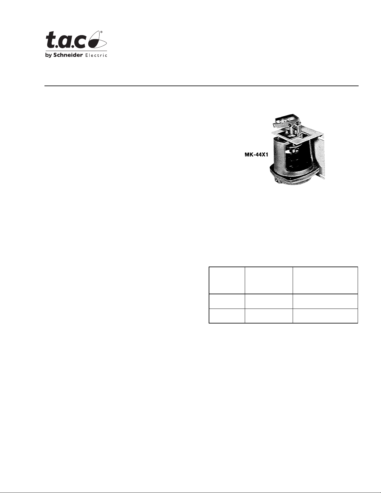
MK-44X1
Pneumatic Damp er Actu ato r
General Instructions
CONSTRUCTION
Units are constructed of a sturdy die cast alumin um housing
enclosing an easily replaceable beaded molded neoprene
diaphragm, steel piston, piston shaft, sintered bronze
shaft-gui de bushing and steel spring .
The molded neoprene diaphragm has a circular bead which
mates with a gr oove in the pr essure housi ng insuri ng positive
locating and sea li ng of the diaphragm with the housing.
Stroke Length: Adjustable 1/2 to 3" (13 t o 76 mm). Factor y
set at 2" (51 mm).
Maximum Safe Air Pressure:
30 psig (207 kPa).
Ambient Temperature Limi ts: -20 to 160°F (-29 to
71
°C).
Mounting: In any position. Mounting bracket, linkage and
connector for 5/16" (8 mm ) di am eter push rod included.
Air Connections: 1/8" FNPT.
Dimensions: 7-7/16" (189 mm) high x 5-3/4" (146 m m) wide
x 4-7/8" (124 mm) deep.
OPTIONS
None.
ACCESSORIES
AM-111 Crank arm for 5/1 6" di am eter damp er sh aft.
AM-112 Crank a rm for 3/8" diameter damper shaft
AM-113 Crank a rm for 1/2" diameter damper shaft
AM-115 Crank arm for 7/1 6" di am eter damp er sh aft
AM-122 Linkage connector straight type
AM-123 Damper clip
AM-125 5/16" x 20 " da m pe r ro d
AM-125- 0 4 8 5/16" x 48 " da m pe r ro d
AM-132 Ball joint connector
AM-161-3 Damper linkage kit
Tool-95 Pneumatic calibration tool kit
Table-1
Nominal Damper
Damper Type
Parallel
Blade
Opposed
Blade
a
MK-4421 requires 15 psi be available to actuator, MK-4461 requires 20
psi be available to actuator.
b
Damper ratings are nominal and based on standard (not low leakage)
damper at 1" W.C. static pressure and 2000 fpm (10 m/s) velocity.
Area for
Proportional
b
Control
4.4 sq. ft. 13.2 sq. ft.
5.6 sq. ft. 16.8 sq. ft.
Nominal Damper Area for
Two-Position Control
a
MK-4421 (8-13 Spring, 20
psi Supply)
b
Printed in U.S.A. 10/08 © Copyright 2008 TAC All Rights Reserved. F-13776-4

Table-2
15 psi
Supply
Single
Press.
System
a
c
20 psi
Supply
Single or
Dual Pres s.
System
c
Nominal Torque
Proportional Control
15 psi
Supply
Dual
Press.
System
15 psi
Supply
Single
Press.
System
b
20 psi Supply
Sing le or Dual
c
Maximum Force
Power Stroke
Dual
Part
Number
Nominal
Operating
Range
Starting
Pressure
Adjustable
Stroke
Based on
1.5 psi
Pressure
to Actuator
15 psi
Supply
Press.
System
psi psi lb. lb. lb. lb. lb-in. lb-in. lb-in.
MK-4401 3-8 3 ± 1 8.25 30.25 38.5 66 7.9 7.9 7.9
MK-4411 5-10 5 ± 1 19.25 19.25 27.5 55 7.9 7.9 7.9
MK-4421 8-13 8 ± 1 35.75 2.75 11 38.5 2.6 7.9 7.9
MK-4451 3-6, 9-12 3 to 6 8.25 8.25 16.5 44 7.9 7.9 7.9
MK-4461 3-6, 11-17 3 to 6 8.25 0 0 16.5 0 0 7.9
a
Force and torques based on factory set stroke and starting pressure.
b
Nominal torque for actuators is based on 1.5 psi pressure change at the actuator..
c
Adjust pressure reducing valve so that listed pressures are available at the actuator.
aReturn
Press.
System
c
Figure-1 Relationship between Strok e and Control Air
Pressure for MK-4451 Two-Stage Actuators.
Figure-2 Relationship between Strok e and Control Air
Pressure for MK-4461 Two-Stage Actuators.
2 © Copyright 2008 TAC All Rights Rese rved. F-13776-4

INSTALLATION
MAINTENANCE
Make all connections in accordance with job piping diagram.
Use 1/4" OD copper or plastic tubing to connect the actuator
to the controller. Units have 1/8" NPT female inl et f or
connection to the suppl y air. Actuators are mounted by means
of four screws (no t in cluded) through the mounting bracket.
See Figure 3 for mounting dimensions.
Insert the pu sh rod in the actuato r and damper connector s and
tighten the set s crews. See Figure 4 for da mper linkage for 90°
rotation. Apply air pressure and run the actuator through the
entire stroke. Readjust linkage if binding occurs during
damper shaft rot ation. Readjustment may also be necessary
if damper shaft does not achieve acceptable rotation.
ADJUSTABLE STARTING
PRESSURE
The start point is t he air pressure value that caus es the
actuator shaf t to just begi n to exte nd. If ad justmen t of sta rting
pressure is req uir ed, turn adjustin g nut supporting the spring
clockwise to dec rease and counterclockwise to increase the
starting pressure, when viewing the actuator from the shaft
end (Figure 3). Eac h ro tation of the ad ju sting nut chan ges t he
starting pressure 0.04 psi (.28 kPa).
Note:
The stroke during the first stage of operat ion (MK-4451
& MK-4461) is adjust able from 0 to 50% of total stroke.
This is a quality produc t. Regular maintenance of the total
system is recommende d to assure sustained opti m um
performance.
DIAPHRAGM REPLACEMENT
If the actuator diaphragm should leak, it may easily be
replaced:
1. Disconnect air li ne to th e actu ator.
2. Remove the screws on the top power housing, the top
cover and the old diaphragm.
3. Insert new diaphr agm over piston.
Note:
Put the top power housing back in place making sure
the bead on the diaphra gm is in the housing groove and the
screw holes are lined up.
4. Tighten the top power housing screws.
Figure-3
Figure-4
F-13776-4 © Copyright 2008 TAC All Rights Reserved. 3

Copyright 2008, TAC
All brand names, trademarks and registered
trademarks are the property of their respective
owners. Information contained within this
document is subject to change without notice.
F-13776-4
TAC
 Loading...