

Page 1

ModiconM340
35012676 10/2019
Modicon M340
Processors
Setup Manual
Original instructions
10/2019
35012676.14
www.schneider-electric.com
Page 2

The information provided in this documentation contains general descriptions and/or technical
characteristics of the performance of the products contained herein. This documentation is not
intended as a substitute for and is not to be used for determining suitability or reliability of these
products for specific user applications. It is the duty of any such user or integrator to perform the
appropriate and complete risk analysis, evaluation and testing of the products with respect to the
relevant specific application or use thereof. Neither Schneider Electric nor any of its affiliates or
subsidiaries shall be responsible or liable for misuse of the information contained herein. If you
have any suggestions for improvements or amendments or have found errors in this publication,
please notify us.
You agree not to reproduce, other than for your own personal, noncommercial use, all or part of
this document on any medium whatsoever without permission of Schneider Electric, given in
writing. You also agree not to establish any hypertext links to this document or its content.
Schneider Electric does not grant any right or license for the personal and noncommercial use of
the document or its content, except for a non-exclusive license to consult it on an "as is" basis, at
your own risk. All other rights are reserved.
All pertinent state, regional, and local safety regulations must be observed when installing and
using this product. For reasons of safety and to help ensure compliance with documented system
data, only the manufacturer should perform repairs to components.
When devices are used for applications with technical safety requirements, the relevant
instructions must be followed.
Failure to use Schneider Electric software or approved software with our hardware products may
result in injury, harm, or improper operating results.
Failure to observe this information can result in injury or equipment damage.
© 2019 Schneider Electric. All rights reserved.
2 35012676 10/2019
Page 3

Table of Contents
Safety Information. . . . . . . . . . . . . . . . . . . . . . . . . . . . . . 5
About the Book . . . . . . . . . . . . . . . . . . . . . . . . . . . . . . . . 9
Part I Modicon M340 PLCs . . . . . . . . . . . . . . . . . . . . . . . .
Chapter 1 Introduction to Modicon M340 PLC Stations . . . . . . . . . 13
Modicon M340 PLC Station. . . . . . . . . . . . . . . . . . . . . . . . . . . . . . . . .
Chapter 2 General Introduction to PLC Station Components . . . . . 15
General Introduction to Processors . . . . . . . . . . . . . . . . . . . . . . . . . . .
General Introduction to Racks . . . . . . . . . . . . . . . . . . . . . . . . . . . . . . .
General Introduction to Power Supply Modules . . . . . . . . . . . . . . . . .
General Introduction to Rack Extender Module. . . . . . . . . . . . . . . . . .
General Introduction to Input/Output Modules. . . . . . . . . . . . . . . . . . .
General Introduction to Counting Modules . . . . . . . . . . . . . . . . . . . . .
General Introduction to Communication . . . . . . . . . . . . . . . . . . . . . . .
Grounding of Installed Modules . . . . . . . . . . . . . . . . . . . . . . . . . . . . . .
Modicon M340H (Hardened) Processors, Modules and Equipment . .
Chapter 3 General Introduction to PLC Networks . . . . . . . . . . . . . . 31
General Introduction to the Modbus Protocol . . . . . . . . . . . . . . . . . . .
General Introduction to an Ethernet Network . . . . . . . . . . . . . . . . . . .
General Introduction to the CANopen Field Bus . . . . . . . . . . . . . . . . .
Chapter 4 Operating Standards and Conditions . . . . . . . . . . . . . . . 35
Standards and Certifications . . . . . . . . . . . . . . . . . . . . . . . . . . . . . . . .
Part II BMX P34 xxxx Processors . . . . . . . . . . . . . . . . . . . .
Chapter 5 Introduction to BMX P34 xxxx Processors . . . . . . . . . . . 39
General Introduction . . . . . . . . . . . . . . . . . . . . . . . . . . . . . . . . . . . . . .
Physical Description of BMX P34 xxxx Processors. . . . . . . . . . . . . . .
USB Link . . . . . . . . . . . . . . . . . . . . . . . . . . . . . . . . . . . . . . . . . . . . . . .
Modbus Link . . . . . . . . . . . . . . . . . . . . . . . . . . . . . . . . . . . . . . . . . . . .
CANopen Link . . . . . . . . . . . . . . . . . . . . . . . . . . . . . . . . . . . . . . . . . . .
Ethernet Link . . . . . . . . . . . . . . . . . . . . . . . . . . . . . . . . . . . . . . . . . . . .
BMX P34 xxxxx Processors Catalog . . . . . . . . . . . . . . . . . . . . . . . . . .
Real-Time Clock . . . . . . . . . . . . . . . . . . . . . . . . . . . . . . . . . . . . . . . . .
11
13
16
17
18
19
20
23
25
26
28
32
33
34
35
37
40
43
45
46
48
50
53
54
35012676 10/2019 3
Page 4

Chapter 6 General Characteristics of the BMX P34 xxxx Processors 57
Electrical Characteristics of the BMX P34 xxxxx Processors. . . . . . . .
General Characteristics of the BMX P34 1000 Processor . . . . . . . . . .
General Characteristics of the BMX P34 2000 Processor . . . . . . . . . .
General Characteristics of the BMX P34 2010/20102 Processors . . .
General Characteristics of the BMX P34 2020 Processor . . . . . . . . . .
General Characteristics of the BMX P34 2030/20302 Processor . . . .
Characteristics of the BMX P34 xxxxx Processor Memory . . . . . . . . .
58
60
62
64
66
68
70
Chapter 7 Installation of BMX P34 xxxx Processors . . . . . . . . . . . . . 73
Fitting of Processors . . . . . . . . . . . . . . . . . . . . . . . . . . . . . . . . . . . . . .
Memory Cards for BMX P34 xxxxx Processors . . . . . . . . . . . . . . . . . .
74
76
Chapter 8 BMX P34 xxxx Processors Diagnostics . . . . . . . . . . . . . . 85
Display . . . . . . . . . . . . . . . . . . . . . . . . . . . . . . . . . . . . . . . . . . . . . . . . .
Searching for Errors Using the Processor Status LEDs. . . . . . . . . . . .
Blocking Errors. . . . . . . . . . . . . . . . . . . . . . . . . . . . . . . . . . . . . . . . . . .
Non-Blocking Errors . . . . . . . . . . . . . . . . . . . . . . . . . . . . . . . . . . . . . . .
Processor or System Errors . . . . . . . . . . . . . . . . . . . . . . . . . . . . . . . . .
86
91
92
94
96
Chapter 9 Processor Performance . . . . . . . . . . . . . . . . . . . . . . . . . . 97
Execution of Tasks. . . . . . . . . . . . . . . . . . . . . . . . . . . . . . . . . . . . . . . .
MAST Task Cycle Time: Introduction. . . . . . . . . . . . . . . . . . . . . . . . . .
MAST Task Cycle Time: Program Processing. . . . . . . . . . . . . . . . . . .
MAST Task Cycle Time: Internal Processing on Input and Output . . .
MAST Task Cycle Time Calculation. . . . . . . . . . . . . . . . . . . . . . . . . . .
FAST Task Cycle Time . . . . . . . . . . . . . . . . . . . . . . . . . . . . . . . . . . . .
Event Response Time . . . . . . . . . . . . . . . . . . . . . . . . . . . . . . . . . . . . .
Index . . . . . . . . . . . . . . . . . . . . . . . . . . . . . . . . . . . . . . . . .
98
102
103
104
107
108
109
111
4 35012676 10/2019
Page 5

Safety Information
Important Information
NOTICE
Read these instructions carefully, and look at the equipment to become familiar with the device
before trying to install, operate, service, or maintain it. The following special messages may appear
throughout this documentation or on the equipment to warn of potential hazards or to call attention
to information that clarifies or simplifies a procedure.
35012676 10/2019 5
Page 6

PLEASE NOTE
Electrical equipment should be installed, operated, serviced, and maintained only by qualified
personnel. No responsibility is assumed by Schneider Electric for any consequences arising out of
the use of this material.
A qualified person is one who has skills and knowledge related to the construction and operation
of electrical equipment and its installation, and has received safety training to recognize and avoid
the hazards involved.
BEFORE YOU BEGIN
Do not use this product on machinery lacking effective point-of-operation guarding. Lack of
effective point-of-operation guarding on a machine can result in serious injury to the operator of
that machine.
UNGUARDED EQUIPMENT
Do not use this software and related automation equipment on equipment which does not have
point-of-operation protection.
Do not reach into machinery during operation.
Failure to follow these instructions can result in death, serious injury, or equipment damage.
This automation equipment and related software is used to control a variety of industrial processes.
The type or model of automation equipment suitable for each application will vary depending on
factors such as the control function required, degree of protection required, production methods,
unusual conditions, government regulations, etc. In some applications, more than one processor
may be required, as when backup redundancy is needed.
Only you, the user, machine builder or system integrator can be aware of all the conditions and
factors present during setup, operation, and maintenance of the machine and, therefore, can
determine the automation equipment and the related safeties and interlocks which can be properly
used. When selecting automation and control equipment and related software for a particular
application, you should refer to the applicable local and national standards and regulations. The
National Safety Council's Accident Prevention Manual (nationally recognized in the United States
of America) also provides much useful information.
In some applications, such as packaging machinery, additional operator protection such as pointof-operation guarding must be provided. This is necessary if the operator's hands and other parts
of the body are free to enter the pinch points or other hazardous areas and serious injury can occur.
Software products alone cannot protect an operator from injury. For this reason the software
cannot be substituted for or take the place of point-of-operation protection.
WARNING
6 35012676 10/2019
Page 7
Ensure that appropriate safeties and mechanical/electrical interlocks related to point-of-operation
protection have been installed and are operational before placing the equipment into service. All
interlocks and safeties related to point-of-operation protection must be coordinated with the related
automation equipment and software programming.
NOTE: Coordination of safeties and mechanical/electrical interlocks for point-of-operation
protection is outside the scope of the Function Block Library, System User Guide, or other
implementation referenced in this documentation.
START-UP AND TEST
Before using electrical control and automation equipment for regular operation after installation,
the system should be given a start-up test by qualified personnel to verify correct operation of the
equipment. It is important that arrangements for such a check be made and that enough time is
allowed to perform complete and satisfactory testing.
EQUIPMENT OPERATION HAZARD
Verify that all installation and set up procedures have been completed.
Before operational tests are performed, remove all blocks or other temporary holding means
used for shipment from all component devices.
Remove tools, meters, and debris from equipment.
Failure to follow these instructions can result in death, serious injury, or equipment damage.
Follow all start-up tests recommended in the equipment documentation. Store all equipment
documentation for future references.
Software testing must be done in both simulated and real environments.
Verify that the completed system is free from all short circuits and temporary grounds that are not
installed according to local regulations (according to the National Electrical Code in the U.S.A, for
instance). If high-potential voltage testing is necessary, follow recommendations in equipment
documentation to prevent accidental equipment damage.
Before energizing equipment:
Remove tools, meters, and debris from equipment.
Close the equipment enclosure door.
Remove all temporary grounds from incoming power lines.
Perform all start-up tests recommended by the manufacturer.
WARNING
35012676 10/2019 7
Page 8

OPERATION AND ADJUSTMENTS
The following precautions are from the NEMA Standards Publication ICS 7.1-1995 (English
version prevails):
Regardless of the care exercised in the design and manufacture of equipment or in the selection
and ratings of components, there are hazards that can be encountered if such equipment is
improperly operated.
It is sometimes possible to misadjust the equipment and thus produce unsatisfactory or unsafe
operation. Always use the manufacturer’s instructions as a guide for functional adjustments.
Personnel who have access to these adjustments should be familiar with the equipment
manufacturer’s instructions and the machinery used with the electrical equipment.
Only those operational adjustments actually required by the operator should be accessible to
the operator. Access to other controls should be restricted to prevent unauthorized changes in
operating characteristics.
8 35012676 10/2019
Page 9

About the Book
At a Glance
Document Scope
This manual describes the hardware installation of the Modicon M340 PLCs and installation of their
main accessories.
This document is also valid for the Modicon M340H PLCs and their accessories.
Validity Note
This documentation is valid for EcoStruxure™ Control Expert 14.1 or later.
You need Modicon M340 firmware 2.4 or later.
The technical characteristics of the devices described in the present document also appear online.
To access the information online:
Step Action
1 Go to the Schneider Electric home page
2 In the Search box type the reference of a product or the name of a product range.
3 If you entered a reference, go to the Product Datasheets search results and click on the
4 If more than one reference appears in the Products search results, click on the reference that
5 Depending on the size of your screen, you may need to scroll down to see the datasheet.
6 To save or print a datasheet as a .pdf file, click Download XXX product datasheet.
www.schneider-electric.com
Do not include blank spaces in the reference or product range.
To get information on grouping similar modules, use asterisks (
reference that interests you.
If you entered the name of a product range, go to the Product Ranges search results and click
on the product range that interests you.
interests you.
.
*
).
The characteristics that are presented in the present document should be the same as those
characteristics that appear online. In line with our policy of constant improvement, we may revise
content over time to improve clarity and accuracy. If you see a difference between the document
and online information, use the online information as your reference.
35012676 10/2019 9
Page 10

Related Documents
Title of documentation Reference number
Modicon M580, M340, and X80 I/O Platforms,
Standards and Certifications
Modicon X80 Racks and Power Supplies, Hardware,
Reference Manual
EcoStruxure™ Control Expert, Program Languages
and Structure, Reference Manual
EcoStruxure™ Control Expert, Operating Modes 33003101 (English),
EIO0000002726 (English),
EIO0000002727 (French),
EIO0000002728 (German),
EIO0000002730 (Italian),
EIO0000002729 (Spanish),
EIO0000002731 (Chinese)
EIO0000002626 (English),
EIO0000002627 (French),
EIO0000002628 (German),
EIO0000002630 (Italian),
EIO0000002629 (Spanish),
EIO0000002631 (Chinese)
35006144 (English),
35006145 (French),
35006146 (German),
35013361 (Italian),
35006147 (Spanish),
35013362 (Chinese)
33003102 (French),
33003103 (German),
33003104 (Spanish),
33003696 (Italian),
33003697 (Chinese)
You can download these technical publications and other technical information from our website
www.schneider-electric.com/en/download
at
.
Product Related Information
WARNING
UNINTENDED EQUIPMENT OPERATION
The application of this product requires expertise in the design and programming of control
systems. Only persons with such expertise should be allowed to program, install, alter, and apply
this product.
Follow all local and national safety codes and standards.
Failure to follow these instructions can result in death, serious injury, or equipment damage.
10 35012676 10/2019
Page 11

ModiconM340
ModiconM340 PLCs
35012676 10/2019
ModiconM340 PLCs
Part I
Modicon M340 PLCs
Subject of this Part
This part provides a general overview of the Modicon M340 PLC configurations and the various
sub-assemblies, as well as the networks and field buses used.
What Is in This Part?
This part contains the following chapters:
Chapter Chapter Name Page
1 Introduction to Modicon M340 PLC Stations 13
2 General Introduction to PLC Station Components 15
3 General Introduction to PLC Networks 31
4 Operating Standards and Conditions 35
35012676 10/2019 11
Page 12

Modicon M340 PLCs
12
35012676 10/2019
Page 13
ModiconM340
Introduction to ModiconM340 PLC Stations
35012676 10/2019
Introduction to ModiconM340 PLC Stations
Chapter 1
Introduction to Modicon M340 PLC Stations
Modicon M340 PLC Station
General
Modicon M340 automated platform processors manage the entire PLC station, which is made up
of discrete I/O modules, analog I/O modules, counting modules, discrete I/O modules, analog I/O
modules, other expert modules, and communication modules. These are distributed across one or
more racks connected on the local bus. Each rack must include a power supply module; the main
rack supports the CPU.
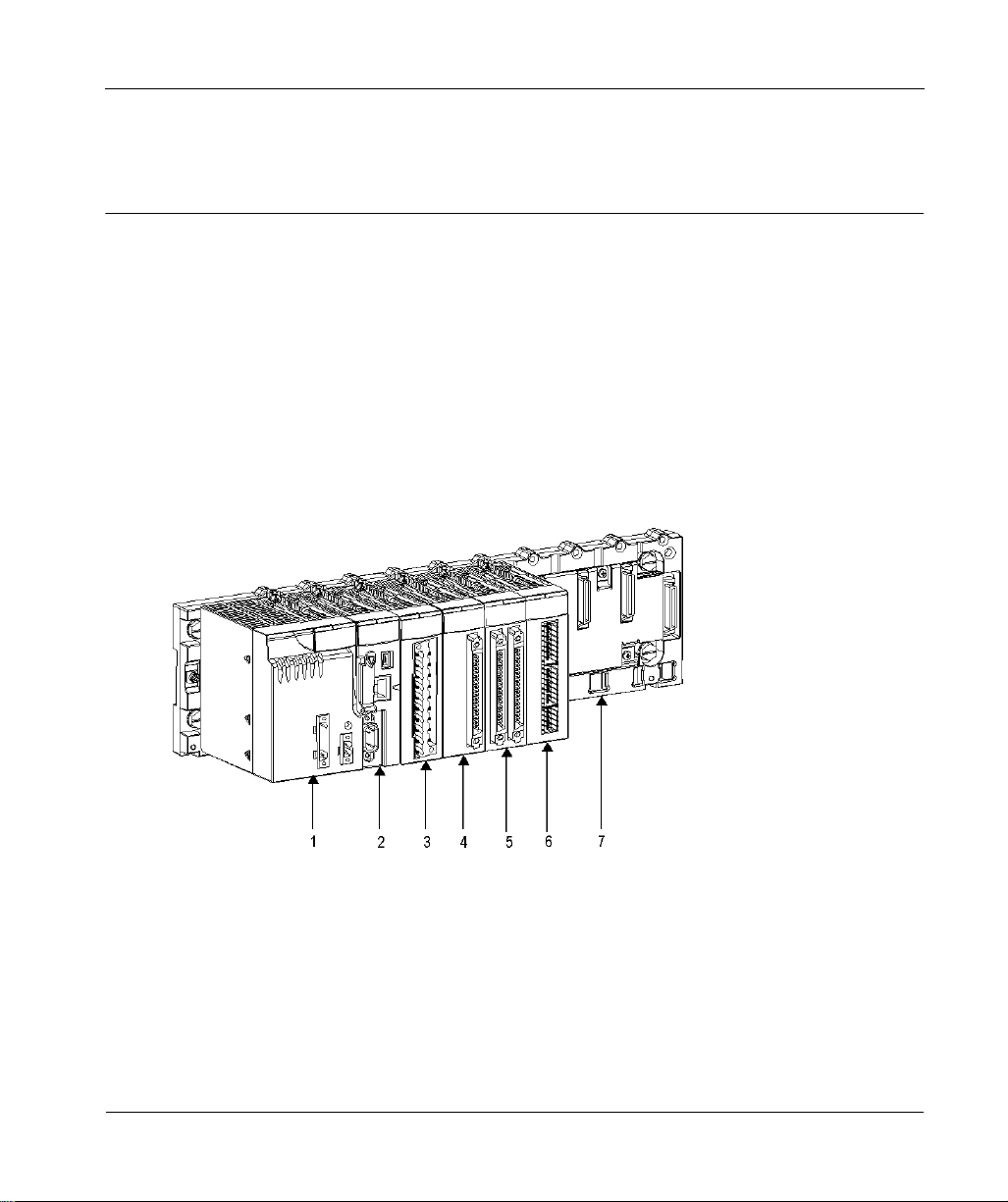
Illustration
The following diagram shows a configuration example for the Modicon M340 PLC with one rack:
35012676 10/2019 13
Page 14

Introduction to Modicon M340 PLC Stations
Number Table
The following table describes the numbered components of the PLC station above.
Number Description
1 Power supply module
2 Processor
3 20-pin terminal block I/O module
4 40-pin single connector I/O module
5 40-pin 2-connector I/O module
6 Counting module
7 8-slot rack
14
35012676 10/2019
Page 15

ModiconM340
General Introduction to PLC station components
35012676 10/2019
General Introduction to PLC Station C omponents
Chapter 2
General Introduction to PLC Station Components
Subject of this Section
This section provides a general overview of the various components of which a PLC station may
consist.
What Is in This Chapter?
This chapter contains the following topics:
General Introduction to Processors 16
General Introduction to Racks 17
General Introduction to Power Supply Modules 18
General Introduction to Rack Extender Module 19
General Introduction to Input/Output Modules 20
General Introduction to Counting Modules 23
General Introduction to Communication 25
Grounding of Installed Modules 26
Modicon M340H (Hardened) Processors, Modules and Equipment 28
Topic Page
35012676 10/2019 15
Page 16

General Introduction to PLC station components
General Introduction to Processors
General
Each PLC station is equipped with a processor, chosen according to the following characteristics:
processing power (number of inputs/outputs managed)
memory capacity
communication ports
For further information, please refer to
Introduction to BMX P34 xxxx Processors, page 39
).
16
35012676 10/2019
Page 17
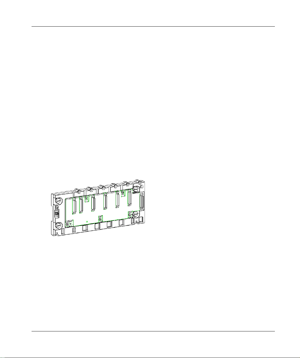
General Introduction to Racks
General
There are various sizes of racks. The following list presents the quantity of slots available for the
CPU and modules for each rack reference:
4 slots: BMXXBP0400(H) or BMEXBP0400(H)
6 slots: BMXXBP0600(H)
8 slots: BMXXBP0800(H) or BMEXBP0800(H)
12 slots: BMXXBP1200(H) or BMEXBP1200(H)
racks with redundant power supplies:
6 slots: BMEXBP0602(H)
10 slots: BMEXBP1002(H)
Each rack includes one extra slot that is reserved for the power supply module, and one slot on the
right is reserved for the BMXXBE1000 rack extender module.
For further information, refer to the chapter
Racks and Power Supplies, Hardware Reference Manual)
Representation of the Racks
The following diagram shows the BMXXPB0400 rack:
General Introduction to PLC station components
Modicon X80 Racks Description (see Modicon X80,
.
35012676 10/2019 17
Page 18
General Introduction to PLC station components
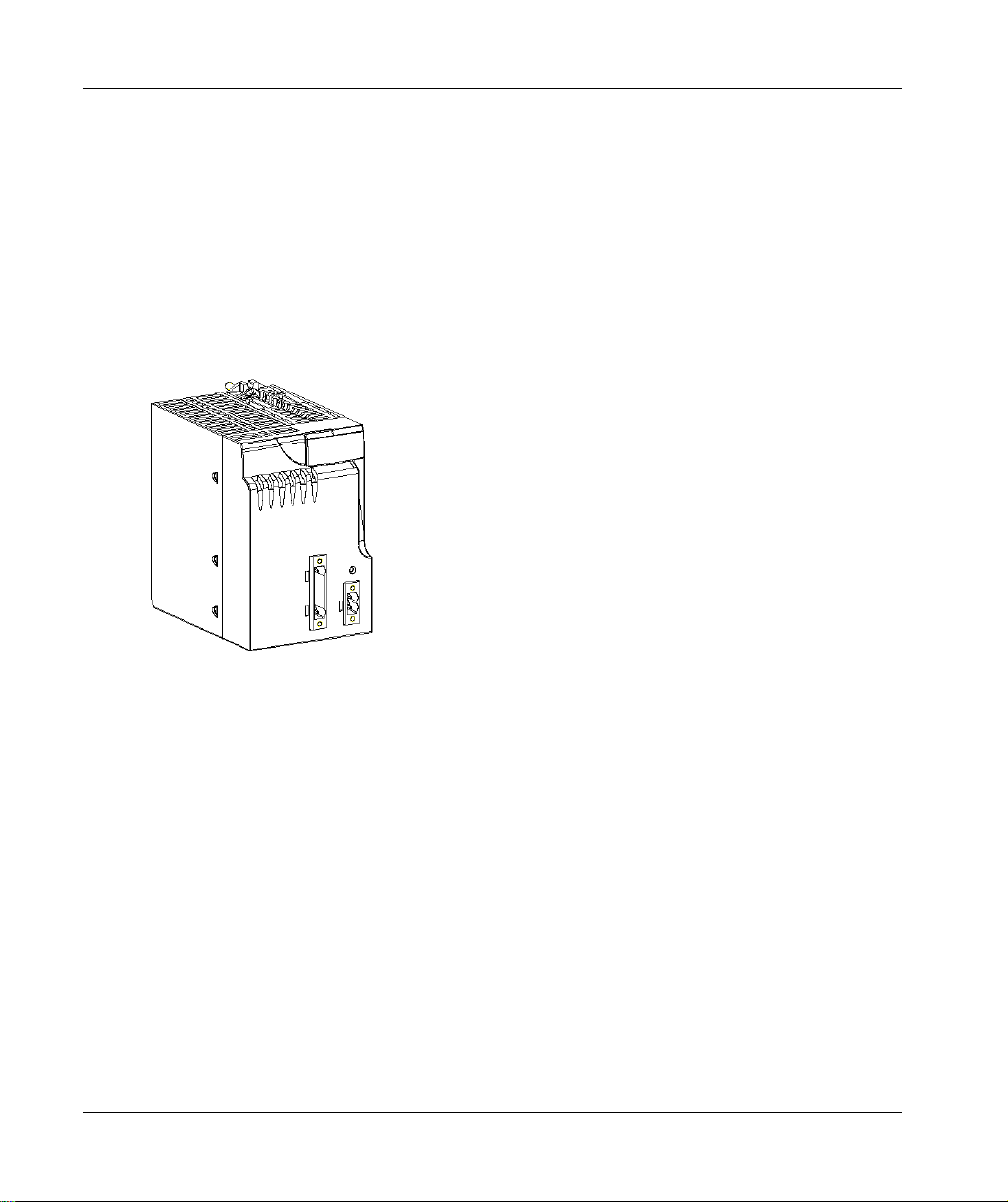
General Introduction to Power Supply Modules
General
Each rack requires one power supply module defined according to the distributed network
(alternating or direct current) and the power necessary at rack level.
For further information, refer to the chapter
(see Modicon X80, Racks and Power Supplies, Hardware Reference Manual)
Illustration
The following illustration shows a BMXCPS•••• power supply module:
Modicon X80 Power Supply Modules Description
.
18
35012676 10/2019
Page 19

General Introduction to Rack Extender Module
General
This module allows connecting a maximum of 4 chained racks, depending on the CPU, distributed
along a maximum length of 30 meters.
For further information, refer to chapter
Racks and Power Supplies, Hardware Reference Manual)
Illustration
Illustration of the BMXXBE1000 rack extender module:
BMXXBE1000 Rack Extender Module (see Modicon X80,
General Introduction to PLC station components
.
35012676 10/2019 19
Page 20
General Introduction to PLC station components
General Introduction to Input/Output Modules
General
The Modicon M340 range includes discrete and analog input/output modules.
Discrete Input/Output
A wide range of discrete input/output modules enables you to select the module best suited to your
needs. The characteristics of these modules differ as follows:
Characteristics Description
Modularity
Type of Inputs
Type of Outputs
Type of Connector
8 channels
16 channels
32 channels
64 channels
Modules with direct current inputs (24 VCC and 48 VCC)
Modules with alternating current inputs (24 VCA, 48 VCA
and 120 VCA)
Modules with relay outputs
Modules with direct current static outputs (24 VCC / 0.1 A
- 0.5 A - 3 A)
Modules with alternating current static outputs (24 VCC /
240 VAC / 3 A)
20-pin terminal blocks
40-pin connectors allowing connection to sensors and pre-
actuators by means of the TELEFAST 2 prewiring system
20
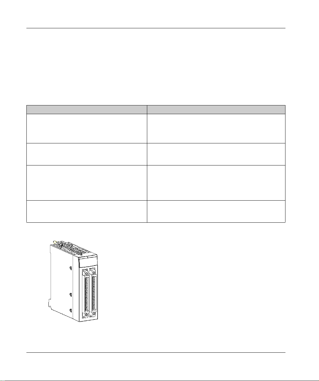
The following illustration shows a discrete input/output modules with 40-pin connectors:
35012676 10/2019
Page 21
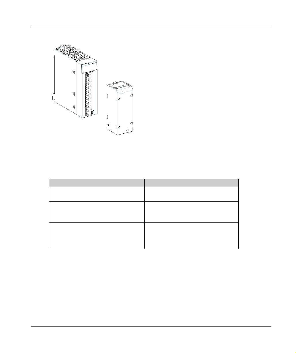
The following illustration shows a discrete input/output module with a 20-pin terminal block:
Analog Inputs/Outputs
A wide range of analog input/output modules enables you to select the module best suited to your
needs. The characteristics of these modules differ as follows:
Characteristics Description
Modularity
Performance and Range of Signals Offered
Type of Connector
General Introduction to PLC station components
2 channels
4 channels
Voltage/current
Thermocouple
Thermowell
20-pin terminal blocks
40-pin connectors allowing connection to
sensors and pre-actuators by means of
the TELEFAST 2 prewiring system
35012676 10/2019 21
Page 22
General Introduction to PLC station components
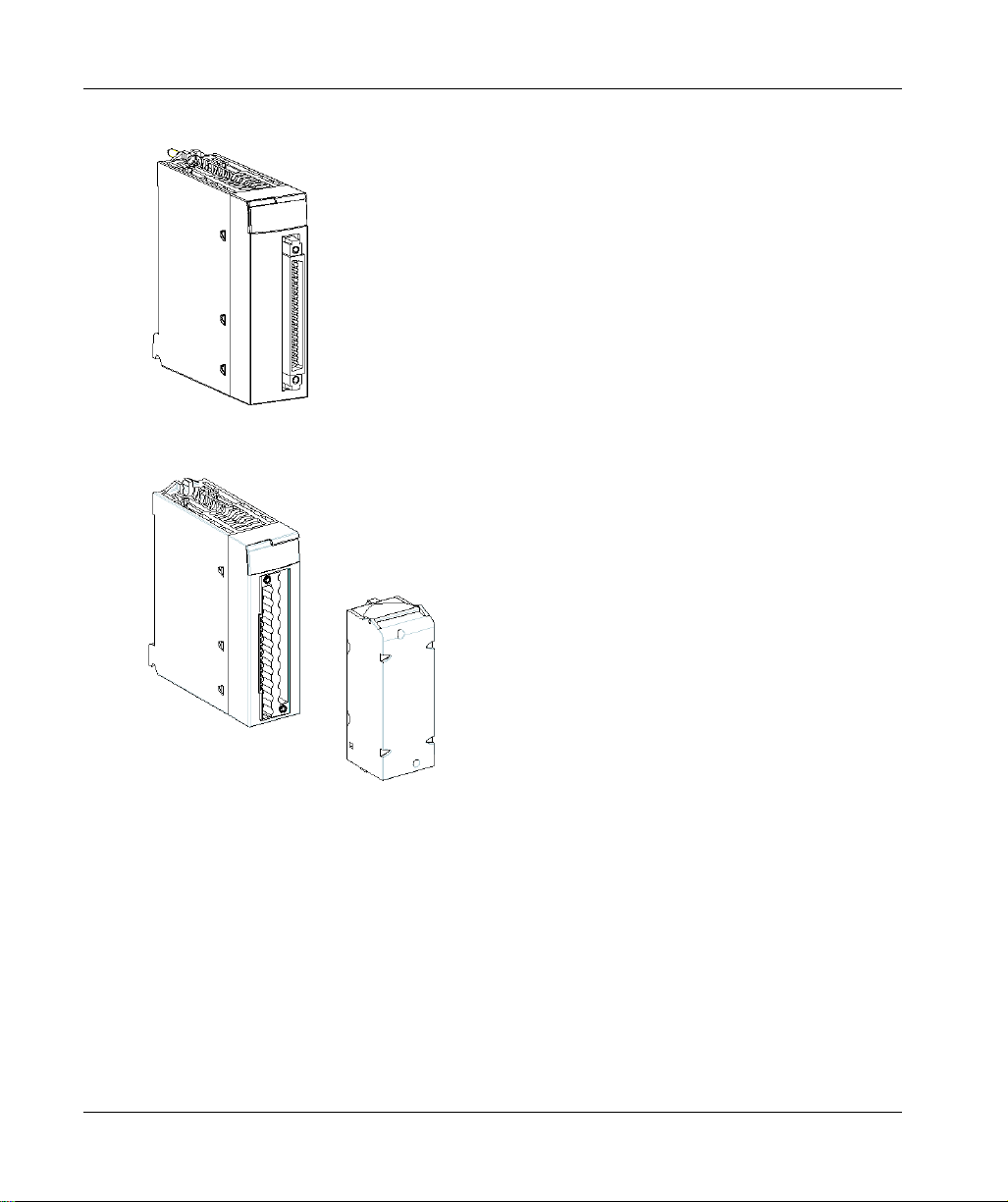
The following illustration shows an analog input/output module with one 40-pin connector:
The following illustration shows an analog input/output module with 20-pin terminal block:
22
35012676 10/2019
Page 23
General Introduction to Counting Modules
General
The PLCs in the Modicon M340 range offer counting functions (downcounting, counting,
counting/downcounting) by utilizing the application-specific counting modules.
Two counting modules are offered:
BMX EHC 0200 module with two counting channels and a maximum acquisition frequency of
60 kHz
BMX EHC 0800 module with eight counting channels and a maximum acquisition frequency of
10 kHz
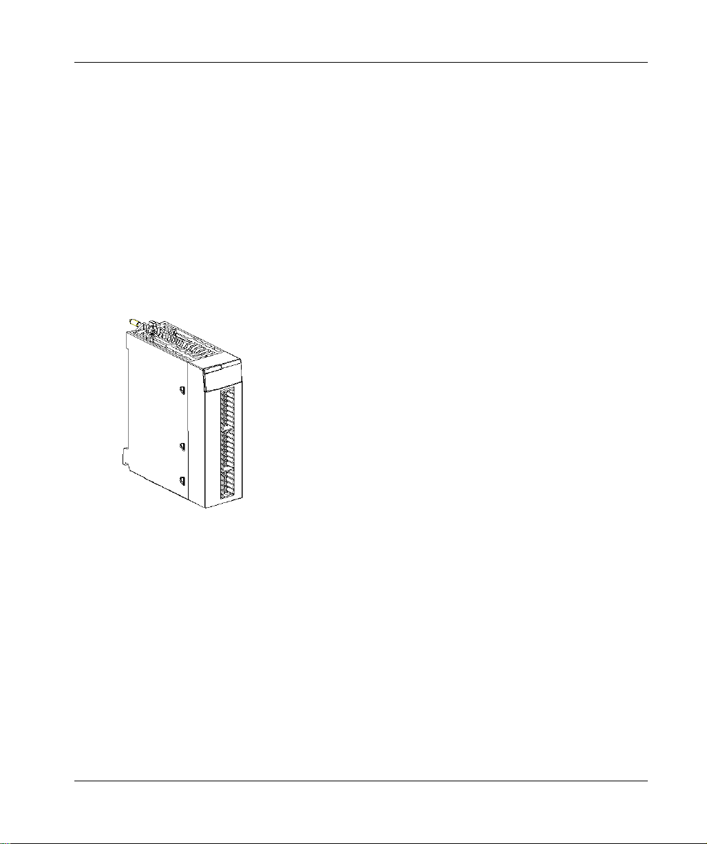
Illustration
The following illustration shows a BMX EHC 0200 counting module:
General Introduction to PLC station components
35012676 10/2019 23
Page 24
General Introduction to PLC station components
The following illustration shows a BMX EHC 0800 counting module:
24
35012676 10/2019
Page 25

General Introduction to Communication
General
PLCs from the Modicon M340 range can be used in different communication modes:
USB
Serial
Ethernet
CANopen
AS-Interface
General Introduction to PLC station components
35012676 10/2019 25
Page 26
General Introduction to PLC station components
Grounding of Installed Modules
General
The grounding of Modicon M340 modules is crucial to avoid electric shock.
Grounding Processors and Power Supplies
HAZARD OF ELECTRIC SHOCK, EXPLOSION OR ARC FLASH
Ensure ground connection contacts are present and not bent out of shape. If they are, do not use
the module and contact your Schneider Electric representative.
Failure to follow these instructions will result in death or serious injury.
UNINTENDED EQUIPMENT OPERATION
Tighten the clamping screws of the modules. A break in the circuit could lead to an unexpected
behavior of the system.
Failure to follow these instructions can result in death, serious injury, or equipment damage.
DANGER
WARNING
26
35012676 10/2019
Page 27
General Introduction to PLC station components
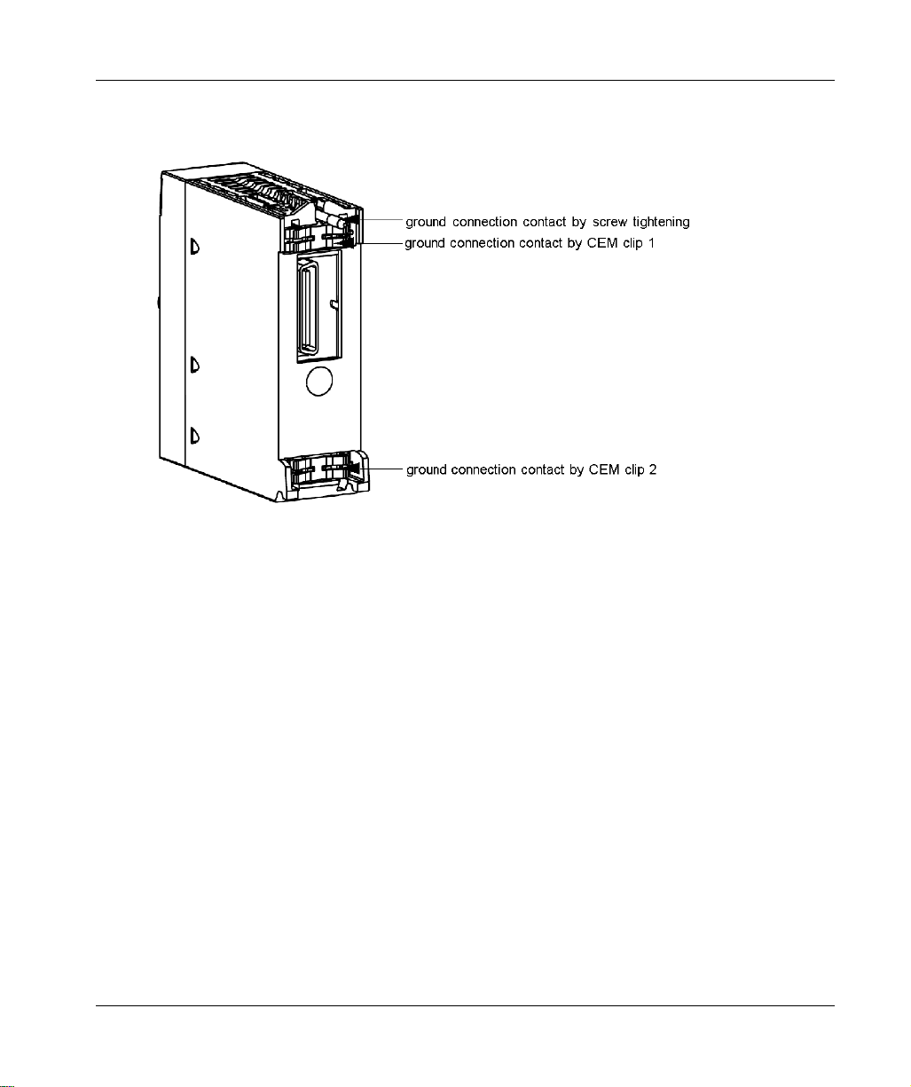
All Modicon M340 modules are equipped with ground connection contacts at the rear for grounding
purposes:
These contacts connect the grounding bus of the modules to the grounding bus of the rack.
35012676 10/2019 27
Page 28

General Introduction to PLC station components
Modicon M340H (Hardened) Processors, Modules and Equipment
At a Glance
Hardened equipment can operate in extended temperature ranges and harsher environments
compared to standard M340 equipment.
NOTE: For more information, refer to chapter
(see Modicon M580, M340, and X80 I/O Platforms, Standards and Certifications)
“H” Equipment
The follow equipment are available in Hardened versions:
CPUs:
BMX P34 2020H
BMX P34 2030 2H
Power Supplies:
BMX CPS 3020H
BMX CPS 3500H
BMX CPS 4002H
Backplanes:
BMX XBP 0400H
BMX XBP 0600H
BMX XBP 0800H
BMX XBP 1200H
BME XBP 0400H
BME XBP 0800H
BME XBP 1200H
BME XBP 0602H
BME XBP 1002H
Backplane Extension:
BMX XBE 1000H
Counting Modules:
BMX ECH 0200H
BMX ECH 0800H
Analog Input Modules:
BMX ART 0414H
BMX ART 0814H
BMX AMI 0810H
Analog Output Modules:
BMX AMO 0210H
BMX AMO 0410H
Installation in More Severe Environments
.
28
35012676 10/2019
Page 29

Analog Input/Output Module:
BMX AMM 0600H
TELEFAST Wiring Accessories
ABE7 CPA 0410H
ABE7 CPA 0412H
Digital Input modules:
BMX DDI 1602H
BMX DDI 1603H
Digital Input/Output modules:
BMX DAI 1602H
BMX DAI 1603H
BMX DAI 1604H
BMX DAI 1614H
BMX DAI 1615H
BMX DDM 16022H
BMX DDM 16025H
Digital Output modules:
BMX DAO 1605H
BMX DAO 1615H
BMX DDO 1602H
BMX DDO 1612H
BMX DRA 0805H
BMX DRA 0815H
BMX DRA 1605H
BMX DRC 0805H
Synchronous Serial Interface (SSI) Modules:
BMX EAE 0300H
General Introduction to PLC station components
35012676 10/2019 29
Page 30

General Introduction to PLC station components
30
35012676 10/2019
Page 31

ModiconM340
General Introduction to PLC Network s
35012676 10/2019
General Introduction to PLC Network s
Chapter 3
General Introduction to PLC Networks
Subject of this Section
This section provides a general overview of PLC networks.
What Is in This Chapter?
This chapter contains the following topics:
General Introduction to the Modbus Protocol 32
General Introduction to an Ethernet Network 33
General Introduction to the CANopen Field Bus 34
Topic Page
35012676 10/2019 31
Page 32

General Introduction to PLC Networks
General Introduction to the Modbus Protocol
General
The Modbus protocol creates a hierarchical structure (one master and several slaves).
The master manages all exchanges according to two types of dialog:
the master exchanges with a slave and awaits the response
the master exchanges with all slaves without awaiting a response (broadcast queries).
Illustration
The following illustration shows a Modbus network:
32
35012676 10/2019
Page 33

General Introduction to an Ethernet Network
General
Ethernet communication essentially targets applications of:
coordination between PLCs
local or centralized monitoring
communication with the production management information system
communication with remote inputs/outputs
Acting as an agent, Ethernet communication also supports management of the network monitoring
standard SNMP.
Illustration
The following illustration shows an Ethernet network:
General Introduction to PLC Networks
35012676 10/2019 33
Page 34

General Introduction to PLC Networks
General Introduction to the CANopen Field Bus
General
The CANopen structure consists of:
a bus master
slave devices, also called nodes
Bus operation is point to point. At any time, each device can send a request on the bus and the
affected devices answer.
Bus request priority is calculated by an identifier in each message.
Illustration
The following example illustrates a CANopen field bus architecture:
34
35012676 10/2019
Page 35

ModiconM340
Operating Standards an d Conditions
35012676 10/2019
Operating Standards an d Conditions
Chapter 4
Operating Standards and Conditions
Standards and Certifications
Download
Click the link that corresponds to your preferred language to download standards and certifications
(PDF format) that apply to the modules in this product line:
Title Languages
Modicon M580, M340, and X80 I/O Platforms,
Standards and Certifications
English:
French:
German:
Italian:
Spanish:
Chinese:
EIO0000002730
EIO0000002726
EIO0000002727
EIO0000002728
EIO0000002729
EIO0000002731
35012676 10/2019 35
Page 36

Operating Standards and Conditions
36
35012676 10/2019
Page 37

ModiconM340
BMXP34 •••• Processors
35012676 10/2019
BMXP34 xxxx Processors
Part II
BMX P34 xxxx Processors
Subject of this Part
This part describes the BMX P34 •••• processors and their installation.
What Is in This Part?
This part contains the following chapters:
Chapter Chapter Name Page
5 Introduction to BMX P34 xxxx Processors 39
6 General Characteristics of the BMX P34 xxxx Processors 57
7 Installation of BMX P34 xxxx Processors 73
8 BMX P34 xxxx Processors Diagnostics 85
9 Processor Performance 97
35012676 10/2019 37
Page 38

BMX P34 •••• Processors
38
35012676 10/2019
Page 39

ModiconM340
Introduction to BMX P34 xxxx Processors
35012676 10/2019
Introduction to BMX P34 xxxx Processors
Chapter 5
Introduction to BMX P34 xxxx Processors
Subject of this Section
This section describes the BMX P34 •••• processors.
What Is in This Chapter?
This chapter contains the following topics:
General Introduction 40
Physical Description of BMX P34 xxxx Processors 43
USB Link 45
Modbus Link 46
CANopen Link 48
Ethernet Link 50
BMX P34 xxxxx Processors Catalog 53
Real-Time Clock 54
Topic Page
35012676 10/2019 39
Page 40

Introduction to BMX P34 xxxx Processors
General Introduction
Introduction
A wide range of BMX P34 ••••• processors, with increasing performance and capability, are
available to respond to various needs.
General
BMX P34 ••••• processors can be installed onto Modicon X80 racks.
Functions
BMX P34 ••••• processors manage the entire PLC station, which includes the following elements:
discrete input/output modules
analog input/output modules
other expert modules
communication modules.
40
35012676 10/2019
Page 41

Illustration
The figure below shows a processor-managed architecture:
Introduction to BMX P34 xxxx Processors
The following table gives the numbered components of the configuration above.
Number Designation
1 Power supply module
2 Processor
3 20-pin terminal block module
4 40-pin single connector module
5 40-pin twin connector module
6 Counting module
7Rack
35012676 10/2019 41
Page 42

Introduction to BMX P34 xxxx Processors
Processor product references
The following diagram shows the location of the product references on the side of the processor:
Main Characteristics of the BMX P34 ••••• Processors
The following table shows the main characteristics of the BMX P34 ••••• processors.
Processor Global maximum
number of
discrete
inputs/outputs
BMX P34 1000 512 128 2048 Kb X - -
BMX P34 2000 1024 256 4096 Kb X - -
BMX P34 2010/20
102
BMX P34 2020 1024 256 4096 Kb X - X
BMX P34 2030/20
302
Key
X Available
- Not available
42
1024 256 4096 Kb X X -
1024 256 4096 Kb - X X
Global
maximum
number of
analog
inputs/outputs
Maximum
memory size
Modbus
Connection
Integrated
CANopen
Master
Connection
Integrated
Ethernet
Connection
35012676 10/2019
Page 43

Physical Description of BMX P34 xxxx Processors
General
The BMX P34 •••• processors differ according to the various components they include.
Illustration
The following diagrams identify the various components of a BMX P34 •••• processor:
Introduction to BMX P34 xxxx Processors
35012676 10/2019 43
Page 44

Introduction to BMX P34 xxxx Processors
Description
The following table shows the components of a BMX P34 •••• processor.
Number Function
1 Display panel
2 USB port
3 Memory card protection port
4 Serial port
5 Serial port identification ring (black)
6 Ethernet port
7 Ethernet port identification ring (green)
8 CANopen port
44
35012676 10/2019
Page 45

USB Link
General
All processors have a USB link.
Description
Two connection cables are available to connect a human-machine interface to the processor USB
port:
BMX XCA USB 018, 1.8 m (5.91 ft) in length
BMX XCA USB 045, 4.5 m (14.76 ft) in length
Both of these cables are fitted with a connector at each end:
Type A USB: connects to the console
Type mini B USB: connects to the processor
In fixed assembly with an XBT type console connected to the processor via the USB port, you are
advised to connect the USB cable to the shielding connection kit
Power Supplies, Hardware Reference Manual)
NOTE: When using the M340, it is strongly recommended to use a USB 2.0 shielded cable
following the USB international standard. The cables BMX XCA USB 018 and BMX XCA USB 045
are designed for this type of use and avoid unexpected behavior of the PLC. Those cables are
shielded and tested against electrical noises.
Introduction to BMX P34 xxxx Processors
(see Modicon X80, Racks and
.
35012676 10/2019 45
Page 46

Introduction to BMX P34 xxxx Processors
Modbus Link
General
The following processors have a built-in communication channel dedicated to serial
communication, and support communication via a Modbus link:
BMX P34 1000,
BMX P34 2000,
BMX P34 2010/20102,
BMX P34 2020.
Introduction to the Serial Port
The following table describes the characteristics of the serial communication channels:.
Characteristic Description
Channel number Channel 0
Protocols supported
Connection RJ45 female connector
Physical link
Modbus protocol (ASCII and RTU)
Character Mode protocol
RS 485 non-insulated serial link
RS 232 non-insulated serial link
46
The following illustration shows the RJ45 serial port:
35012676 10/2019
Page 47

Introduction to BMX P34 xxxx Processors
The following table shows the pin assignment of the serial port for the BMX P34 xxxxx processors:
The RJ45 connector has eight pins. The pins used differ according to the physical link used.
The pins used by the RS 232 serial link are as follows:
Pin 1: RXD signal
Pin 2: TXD signal
Pin 3: RTS signal
Pin 6: CTS signal
The pins used by the RS 485 serial link are as follows:
Pin 4: D1 signal
Pin 5: D0 signal
Pins 7 and 8 are dedicated to the power supply of the man-machine interface via the serial link:
Pin 7: 5 VDC/190 mA network power supply
Pin 8: common of the network power supply (0 V)
NOTE: The RS 232 4-wire, RS 485 2-wire, and RS 485 2-wire and power supply cables all use the
same RJ45 male connector.
35012676 10/2019 47
Page 48

Introduction to BMX P34 xxxx Processors
CANopen Link
Introduction
The following processors have a built-in communication channel dedicated to CANopen
communication,and support communication via CANopen link:
BMX P34 2010/20102,
BMX P34 2030/20302.
Introduction to the CANopen Port
The following illustration shows the position of the BMX P34 2030 processor’s CANopen port:
48
35012676 10/2019
Page 49

CANopen Connectors
The CANopen port of the processor module is fitted with a SUB-D9 connection.
The following illustration shows the processor CANopen port and the pins labels:
The following table shows the pin assignment of the CANopen link.
Pin Signal Description
1- Reserved
2 CAN_L CAN_L bus line (low dominant)
3 CAN_GND CAN ground
4- Reserved
5 Reserved Optional CAN protection
6 (GND) Optional ground
7 CAN_H CAN_H bus line (high dominant)
8- Reserved
9 Reserved Positive external CAN power supply
Introduction to BMX P34 xxxx Processors
(dedicated to the power supply of optocouplers and
transmitters/receivers)
Optional
NOTE: CAN_SHLD and CAN_V+ are not installed on the Modicon M340 range processors. These
are reserved connections.
35012676 10/2019 49
Page 50

Introduction to BMX P34 xxxx Processors
Ethernet Link
General
The following processors have a built-in communication channel dedicated to Ethernet
communication, with 2 rotary switches which enable easy selection of the IP address processor.
BMX P34 2020,
BMX P34 2030/20302.
NOTE: These processors have only one IP address.
Introduction to the Ethernet Port
The following illustration shows the processor of the RJ45 Ethernet port:
The following illustration shows the pin assignment of the Ethernet port:
Introduction to the MAC address
The MAC address is located on the front panel of the processor below the processor display panel.
50
35012676 10/2019
Page 51

Introduction to the Rotary Switches
This processor operates as a single node on an Ethernet and possibly other networks. The module
must have a unique IP address. The 2 rotary switches on the back of the module provide a simple
way to select an IP address:
NOTE: Set the arrow firmly into the desired position. If you do not feel the switch click into place,
the value of the switch may be incorrect or undetermined.
Each rotary switch position that you can use to set a valid IP address is marked on the module.
The following information summarizes the valid address settings:
device name: for a switch-set device name, select a numeric value from 00 to 159. You can use
both switches:
On the upper switch (TENS digit), the available settings are 0 to 15
On the lower switch (ONES digit), the available settings are 0 to 9.
For example, a BMX P34 2020 processor with the switch setting in the above figure is assigned
the DHCP device name BMX_2020_123.
The selection on the lower switch of any non-numeric parameter (BOOTP, STORED, CLEAR
IP, DISABLED) makes the setting on the upper switch inconsequential.
BOOTP: To get an IP address from a BOOTP server, select either of the two BOOTP positions
on the bottom switch.
STORED: The device uses the application’s configured (stored) parameters.
CLEAR IP: The device uses the default IP parameters.
DISABLED: The device does not respond to communications.
The functionality of the rotary switch when used in conjunction with the IP Configuration tab
(see Modicon M340 for Ethernet, Communications Modules and Processors, User Manual)
discussed throughout the IP Address chapter
Modules and Processors, User Manual)
Introduction to BMX P34 xxxx Processors
is
(see Modicon M340 for Ethernet, Communications
.
35012676 10/2019 51
Page 52

Introduction to BMX P34 xxxx Processors
Switch Labels
To assist you in setting the rotary switches to their proper positions, a label is affixed to the right
side of the module. The switch settings are described in this table:
Upper Switch
0 to 9: Tens value for the device name
(0, 10, 20 . . . 90)
10(A) to 15(F): Tens value for the
device name (100, 110, 120 . . . 150)
Lower Switch
0 to 9: Ones value for the device name
(0, 1, 2...9)
Bootp: Set the switch to A or B to
receive an IP address from a BOOTP
server.
Stored: Set the switch to C or D to use
the application’s configured (stored)
parameters.
Clear IP: Set the switch to E to use the
default IP parameters.
Disabled: Set the switch to F to disable
communications.
52
35012676 10/2019
Page 53

BMX P34 xxxxx Processors Catalog
Introduction
The choice of BMX P34 xxxxx processor is made, primarily, according to its characteristics and
possibilities.
BMX P34 xxxxx Processors Catalog
The following table describes the important maximum characteristics of the BMX P34 xxxxx
processors.
Introduction to BMX P34 xxxx Processors
Characteristic BMX P34 1000 BMX P34 2000 BMX P34 2010
/20102
Maximum
Number of
channels
Maximum
Number of
modules
Memory
size
Legend 1 The AS-i field bus requires at least PLC Operating System V2.10.
Discrete rack
inputs/outputs
Analog
inputs/outputs
Expert
channels
(counting, PTO,
MPS, NOM,
etc.)
Embedded
Serial port
Embedded
Ethernet port
Embedded
CANopen port
Network
communication
(TCP/IP)
AS-i fieldbus
communication
User
application
512 1024 1024 1024 1024
128 256 256 256 256
20 36 36 36 36
1111-
---11
--1-1
23333
1
24444
2048 Kb 4096 Kb 4096 Kb 4096 Kb 4096 Kb
BMX P34 2020 BMX P34 2030
/20302
35012676 10/2019 53
Page 54

Introduction to BMX P34 xxxx Processors
Real-Time Clock
Introduction
Each BMX P34 xxxxx processor has a real-time clock which manages:
The current date and time
The date and time of the last application shut-down
When power of the processor is turned off, the real-time clock continues counting during four
weeks. This duration is guarantied for a temperature below 45°C (113°F). At a higher temperature
this duration is reduced. No maintenance is requested for a real-time clock back up.
Current Date and Time
The processor updates the current date and time in the system words %SW49...%SW53 and %SW70.
This data is in BCD (Binary Coded Decimal).
System Word Most Significant Byte Least Significant Byte
%SW49
%SW50
%SW51
%SW52
%SW53
%SW70
00 Days of the week in the range of values
Seconds (0 - 59) 00
Hours (0 - 23) Minutes (0 - 59)
Month (1 - 12) Days of the month (1 - 31)
Century (0 - 99) Year (0 - 99)
1 - 7 (1 for Monday and 7 for Sunday)
Week (1 - 52)
Accessing the Date and Time
You can access the date and time as follows:
through the processor debug screen.
with the program:
Reading system words: %SW49 - %SW53 if the system bit %S50 is at 0,
immediate update: writing system words %SW50 to %SW53 if the system bit %S50 is at 1,
incremental update: writing the system word %SW59. With this word the date and time can be
set field by field from the current value (if the system bit %S59 is at 1), or an overall
increment/decrement can be done.
The following table shows the function performed by each bit in the word %SW59.
Bit Range Function
0 Increments the day of the week
1 Increments the seconds
2 Increments the minutes
3 Increments the hours
54
35012676 10/2019
Page 55

Bit Range Function
4 Increments the days
5 Increments the months
6 Increments the years
7 Increments the centuries
8 Decrements the day of the week
9 Decrements the seconds
10 Decrements the minutes
11 Decrements the hours
12 Decrements the days
13 Decrements the months
14 Decrements the years
15 Decrements the centuries
NOTE: The function is performed when the corresponding bit %S59 is at 1.
NOTE: The processor does not automatically manage Daylight Savings Time.
Date and Time of the Last Application Shutdown
The date and time of the last application shutdown are in BCD in the system words %SW54 - %SW58.
Introduction to BMX P34 xxxx Processors
System Word Most Significant Byte Least Significant Byte
%SW54
%SW55
%SW56
%SW57
%SW58
Seconds (0 to 59) 00
Hours (0 to 23) Minutes (0 to 59)
Month (1 to 12) Days of the month (1 to 31)
Century (0 to 99) Year (0 to 99)
Day of the week (1 to 7) Reason for the last application shutdown
The reason for the last application shutdown can be accessed by reading the least significant byte
of the system word %SW58 (value in BCD) which can have the following values.
Word value %SW58 Meaning
1 Application switched to STOP mode.
2 Application stopped by watchdog.
4 Power loss or memory card lock operation.
5 Stop on hardware fault.
6 Stop on software fault (HALT instruction, SFC errors,
35012676 10/2019 55
application CRC check fail, undefined system function call,
etc). Details on the software fault type are stored in %SW125.
Page 56

Introduction to BMX P34 xxxx Processors
56
35012676 10/2019
Page 57

ModiconM340
General Characteristics of the BMXP34 •••• Processors
35012676 10/2019
General Characteristics of the BMXP34 xxxx Processors
Chapter 6
General Characteristics of the BMX P34 xxxx Processors
Subject of this Section
This section describes the general characteristics of the BMX P34 •••• processors used during
installation.
What Is in This Chapter?
This chapter contains the following topics:
Electrical Characteristics of the BMX P34 xxxxx Processors 58
General Characteristics of the BMX P34 1000 Processor 60
General Characteristics of the BMX P34 2000 Processor 62
General Characteristics of the BMX P34 2010/20102 Processors 64
General Characteristics of the BMX P34 2020 Processor 66
General Characteristics of the BMX P34 2030/20302 Processor 68
Characteristics of the BMX P34 xxxxx Processor Memory 70
Topic Page
35012676 10/2019 57
Page 58

General Characteristics of the BMX P34 •••• Processors
Electrical Characteristics of the BMX P34 xxxxx Processors
General
The processors can support certain devices which do not have their own power supply. It is,
therefore, necessary to take the power consumption of these devices into account when
establishing the overall power consumption breakdown.
Processor Power Consumption
The following table shows the power consumption for all the BMX P34 xxxxx processors with no
connected devices.
Processor Average Consumption
BMX P34 1000 72 mA
BMX P34 2000 72 mA
BMX P34 2010/20102 90 mA
BMX P34 2020 95 mA
BMX P34 2030/20302 135 mA
NOTE: The processor power consumption values are measured at the 24 V_BAC output of the
power supply module, which is the only power supply output used by the processors.
NOTE: When a device consumes power on the processor serial port connection, its power needs
to be added to the power consumed by the processor. The power supplied by the serial port is
5 VCC/190 mA.
58
NOTICE
IMPROPER POWER SUPPLY
Only use network power-supplied devices tested by Schneider Electric.
Failure to follow these instructions can result in equipment damage.
NOTE: It is possible to use network power-supplied devices not tested by Schneider Electric.
However, their operation is not guaranteed. For further information, please contact your Schneider
sales office.
35012676 10/2019
Page 59

Processor Dissipated Power
The following table shows the average dissipated power for all the BMX P34 xxxxx processors with
no connected devices.
Processor Average Dissipated Power
BMX P34 1000 1.7 W
BMX P34 2000 1.7 W
BMX P34 2010/20102 2.2 W
BMX P34 2020 2.3 W
BMX P34 2030/20302 3.2 W
General Characteristics of the BMX P34 •••• Processors
35012676 10/2019 59
Page 60

General Characteristics of the BMX P34 •••• Processors
General Characteristics of the BMX P34 1000 Processor
General
The characteristics of the BMX P34 1000 processor are presented below.
Ruggedized Version
The BMX P34 1000H (hardened) equipment is the ruggedized version of the BMX P34 1000
(standard) equipment. It can be used at extended temperatures and in harsh chemical
environments.
For more information, refer to chapter
M580, M340, and X80 I/O Platforms, Standards and Certifications)
Altitude Operating Conditions
The characteristics apply to the modules BMX P34 1000, and BMX P34 1000H for use at altitude
up to 2000 m (6560 ft). When the modules operate above 2000 m (6560 ft), apply additional
derating.
For detailed information, refer to chapter
M340, and X80 I/O Platforms, Standards and Certifications)
Installation in More Severe Environments (see Modicon
Operating and Storage Conditions (see Modicon M580,
.
.
60
35012676 10/2019
Page 61

BMX P34 1000 Processor Characteristics
The following table shows the general characteristics of the BMX P34 1000 processor.
Characteristic Available
Operating Temperature BMX P34 1000 0...+60 °C (+32...+140 °F)
BMX P34 1000H -25...+70 °C (-13...+158 °F)
Functions Maximum
Savable Application Data Memory Capacity 128 Kb
Application
Structure
Application Code
Execution Speed
Execution Time One basic Boolean instruction 0.18 μs (theoretical)
number of
Maximum
number of
modules
Savable real-time clock Yes
MAST task 1
FAST task 1
Event processing 32
Internal
RAM
One basic digital instruction 0.25 μs (theoretical)
One floating point instruction 1.74 μs (theoretical)
Discrete rack inputs/outputs 512
Analog rack inputs/outputs 128
Expert channels 20
Ethernet channels 2
AS-I Field Bus 2
Simultaneous communication EF 8
USB 1
Embedded Serial Modbus link port 1
Embedded CANopen master port -
Embedded Ethernet port -
100% Boolean 5.4 Kins/ms (1)
65% Boolean + 35% digital 4.2 Kins/ms (1)
General Characteristics of the BMX P34 •••• Processors
(1) Kins: 1024 instructions (list), theoretical
35012676 10/2019 61
Page 62

General Characteristics of the BMX P34 •••• Processors
General Characteristics of the BMX P34 2000 Processor
General
The characteristics of the BMX P34 2000 processor are presented below.
Altitude Operating Conditions
The characteristics apply to the module BMX P34 2000 for use at altitude up to 2000 m (6560 ft).
When the module operates above 2000 m (6560 ft), apply additional derating.
For detailed information, refer to chapter
M340, and X80 I/O Platforms, Standards and Certifications)
Operating and Storage Conditions (see Modicon M580,
.
62
35012676 10/2019
Page 63

BMX P34 2000 Processor Characteristics
The following table shows the general characteristics of the BMX P34 2000 processor.
Characteristic Available
Operating Temperature 0...+60 °C (+32...+140 °F)
Functions Maximum
number of
Maximum
number of
modules
Savable real-time clock Yes
Savable Application Data Memory Capacity 256 Kb
Application
Structure
Application Code
Execution Speed
Execution Time One basic Boolean instruction 0.12 μs
MAST task 1
FAST task 1
Event processing 64
Internal
RAM
One basic digital instruction 0.17 μs
One floating point instruction 1.16 μs
Discrete rack inputs/outputs 1024
Analog rack inputs/outputs 256
Counting channels 36
Ethernet channels 2
AS-i Field Bus 4
Simultaneous communication EF 16
USB 1
Embedded Serial Modbus link port 1
Embedded CANopen master port -
Embedded Ethernet port -
100% Boolean 8.1 Kins/ms (1)
65% Boolean + 35% digital 6.4 Kins/ms (1)
General Characteristics of the BMX P34 •••• Processors
(1) Kins: 1024 instructions (list)
35012676 10/2019 63
Page 64

General Characteristics of the BMX P34 •••• Processors
General Characteristics of the BMX P34 2010/20102 Processors
Altitude Operating Conditions
The characteristics apply to the modules BMX P34 2010, and BMX P34 20102 for use at altitude
up to 2000 m (6560 ft). When the modules operate above 2000 m (6560 ft), apply additional
derating.
For detailed information, refer to chapter
M340, and X80 I/O Platforms, Standards and Certifications)
Operating and Storage Conditions (see Modicon M580,
.
64
35012676 10/2019
Page 65

BMX P34 2010/20102 Processors Characteristics
The following table shows the general characteristics of the BMX P34 2010/20102 processors.
Characteristic Available
Operating Temperature 0...+60 °C (+32...+140 °F)
Functions Maximum
number of
Maximum
number of
modules
Savable real-time clock Yes
Savable Application Data Memory Capacity 256 Kb
Application
Structure
Application Code
Execution Speed
Execution Time One basic Boolean instruction 0.12 μs
MAST task 1
FAST task 1
Event processing 64
Internal
RAM
One basic digital instruction 0.17 μs
One floating point instruction 1.16 μs
Discrete rack inputs/outputs 1024
Analog rack inputs/outputs 256
Expert channels 36
Ethernet channels 2
AS-i field Bus BMX P34 2010: 0
Simultaneous communication EF 16
USB 1
Embedded Serial Modbus link port 1
Embedded CANopen master port 1
Embedded Ethernet port -
100% Boolean 8.1 Kins/ms (1)
65% Boolean + 35% digital 6.4 Kins/ms (1)
General Characteristics of the BMX P34 •••• Processors
BMX P34 20102: 4
(1) Kins: 1024 instructions (list)
NOTE: Expert mode function is available for BMX P34 20102 processors.
35012676 10/2019 65
Page 66

General Characteristics of the BMX P34 •••• Processors
General Characteristics of the BMX P34 2020 Processor
General
The characteristics of the BMX P34 2020 processor are presented below.
Ruggedized Version
The BMX P34 2020H (hardened) equipment is the ruggedized version of the BMX P34 2020
(standard) equipment. It can be used at extended temperatures and in harsh chemical
environments.
For more information, refer to chapter
M580, M340, and X80 I/O Platforms, Standards and Certifications)
Altitude Operating Conditions
The characteristics apply to the modules BMX P34 2020, and BMX P34 2020H for use at altitude
up to 2000 m (6560 ft). When the modules operate above 2000 m (6560 ft), apply additional
derating.
For detailed information, refer to chapter
M340, and X80 I/O Platforms, Standards and Certifications)
Installation in More Severe Environments (see Modicon
Operating and Storage Conditions (see Modicon M580,
.
.
66
35012676 10/2019
Page 67

BMX P34 2020 Processor Characteristics
The following table shows the general characteristics of the BMX P34 2020 processor.
Characteristic Available
Operating Temperature BMX P34 2020 0...+60 °C (+32...+140 °F)
BMX P34 2020H -25...+70 °C (-13...+158 °F)
Functions Maximum
Savable Application Data Memory Capacity 256 Kb
Application
Structure
Application Code
Execution Speed
Execution Time One basic Boolean instruction 0.12 μs
number of
Maximum
number of
modules
Savable real-time clock Yes
MAST task 1
FAST task 1
Event processing 64
Internal
RAM
One basic digital instruction 0.17 μs
One floating point instruction 1.16 μs
Discrete rack inputs/outputs 1024
Analog rack inputs/outputs 256
Expert channels 36
Ethernet channels 3
AS-i Field Bus 4
Simultaneous communication EF 16
USB 1
Embedded Serial Modbus link port 1
Embedded CANopen master port -
Embedded Ethernet port 1
100% Boolean 8.1 Kins/ms (1)
65% Boolean + 35% digital 6.4 Kins/ms (1)
General Characteristics of the BMX P34 •••• Processors
(1) Kins: 1024 instructions (list)
35012676 10/2019 67
Page 68

General Characteristics of the BMX P34 •••• Processors
General Characteristics of the BMX P34 2030/20302 Processor
Ruggedized Version
The BMX P34 20302H (hardened) equipment is the ruggedized version of the BMX P34 20302
(standard) equipment. It can be used at extended temperatures and in harsh chemical
environments.
For more information, refer to chapter
M580, M340, and X80 I/O Platforms, Standards and Certifications)
Altitude Operating Conditions
The characteristics apply to the modules BMX P34 2030, BMX P34 20302, and BMX P34 20302H
for use at altitude up to 2000 m (6560 ft). When the modules operate above 2000 m (6560 ft), apply
additional derating.
For detailed information, refer to chapter
M340, and X80 I/O Platforms, Standards and Certifications)
Installation in More Severe Environments (see Modicon
.
Operating and Storage Conditions (see Modicon M580,
.
68
35012676 10/2019
Page 69

BMX P34 2030/20302 Processor Characteristics
The following table shows the general characteristics of the BMX P34 2030/20302 processor.
Characteristic Available
Operating Temperature BMX P34 2030/20302 0...+60 °C (+32...+140 °F)
BMX P34 20302H -25...+70 °C (-13...+158 °F)
Functions Maximum
Savable Application Data Memory Capacity 256 Kb
Application
Structure
Application Code
Execution Speed
Execution Time One basic Boolean instruction 0.12 μs
number of
Maximum
number of
modules
Savable real-time clock Yes
MAST task 1
FAST task 1
Event processing 64
Internal
RAM
One basic digital instruction 0.17 μs
One floating point instruction 1.16 μs
Discrete rack inputs/outputs 1024
Analog rack inputs/outputs 256
Expert channels 36
Ethernet channels 3
AS-i Field Bus BMX P34 2030: 0
Simultaneous communication EF 16
USB 1
Embedded Serial Modbus link port -
Embedded CANopen master port 1
Embedded Ethernet port 1
100% Boolean 8.1 Kins/ms (1)
65% Boolean + 35% digital 6.4 Kins/ms (1)
General Characteristics of the BMX P34 •••• Processors
BMX P34 20302: 4
(1) Kins: 1024 instructions (list)
NOTE: Expert mode function is available for BMX P34 20302 processors.
35012676 10/2019 69
Page 70

General Characteristics of the BMX P34 •••• Processors
Characteristics of the BMX P34 xxxxx Processor Memory
Introduction
The following pages present the main characteristics of the BMX P34 ••••• processor memory.
Size of Located Data
The following table shows maximum size of located data according to the type of processor:
Type of
Objects
Internal bits
Input/Output
bits
System bits
Internal words
Constant
words
System words
Address Maximum Size for
the BMX P34 1000
Processor
%Mi
%Ir.m.c
%Qr.m.c
%Si
%MWi
%KWi
%SWi
16250 256 32634 512
(1) (1) (1) (1)
128 128 128 128
32464 512 32464 1024
32760 128 32760 256
168 168 168 168
(1) Depends on the equipment configuration declared (input/output modules).
Size of unlocated Data
Unlocated data is as follows:
Elementary Data Types (EDT)
Derived Data Types (DDT)
DFB and EFB function block data.
Size of Located and Unlocated Data
The total size of located and unlocated data is limited to:
128 kilobytes for the BMX P34 1000 processor.
256 kilobytes for the BMX P34 20x0x processors
Default Size for the
BMX P34 1000
Processor
Maximum Size for
the BMX P34 20x0x
Processors
Default Size for the
BMX P34 20x0x
Processors
70
35012676 10/2019
Page 71

Size of Located Data in Case of State RAM
The following table shows maximum and default size of located data in case of State RAM
configuration according to the type of processor.
General Characteristics of the BMX P34 •••• Processors
Type of
Objects
output bits
and internal
bits
input bits and
internal bits
input words
and internal
words
output words
and internal
words
Address BMX P34 1000 V2.40 Processor BMX P34 2000, 20102, 2020, 20302
Processors (all V2.40)
Maximum Size Default Size Maximum Size Default Size
%M (0x)
%I (1x)
%IW (3x)
%MW (4x)
32765 752 65530 1504
32765 752 65530 1504
32765 256 65530 512
32765 256 65530 512
NOTE: To use State RAM configuration you need Modicon M340 firmware 2.4 or later.
NOTE: When changing the processor type from a BMX P34 2xxx to a BMX P34 1000, remove the
unavailable features (DFBs, EFBs...) in the sections and in the data editor too (Purge Unused FB
Instances, Purge Unused Types, Purge Unused Private Data Instance if needed). Otherwise the
application can't be built.
35012676 10/2019 71
Page 72

General Characteristics of the BMX P34 •••• Processors
72
35012676 10/2019
Page 73

ModiconM340
Installation of BMX P34 •••• Processor s
35012676 10/2019
Installation of BMX P34 xxxx Process ors
Chapter 7
Installation of BMX P34 xxxx Processors
Subject of this Section
This section deals with the installation of BMX P34 •••• processors and memory extension cards.
What Is in This Chapter?
This chapter contains the following topics:
Fitting of Processors 74
Memory Cards for BMX P34 xxxxx Processors 76
Topic Page
35012676 10/2019 73
Page 74

Installation of BMX P34 •••• Processors
Fitting of Processors
At a Glance
BMX P34 xxxxx processors are powered by the rack bus.
Fitting operations (installation, assembly, and disassembly) are described below.
Installation Precautions
A BMX P34 xxxxx processor is always installed on the rack in slot marked 00.
Before installing a module, you must take off the protective cap from the module connector located
on the rack.
HAZARD OF ELECTRIC SHOCK
Disconnect all power sources before installing the processor.
Failure to follow these instructions will result in death or serious injury.
Installation
The following illustration shows a BMX P34 2010 processor mounted on a BMX XBP 0800 rack:
DANGER
74
The following table describes the different elements which make up the assembly below.
Number Description
1 Processor
2 Standard rack
35012676 10/2019
Page 75

Installation of BMX P34 •••• Processors
Installing the Processor on the Rack
The following table presents the procedure for installing a processor on a rack.
Step Action Illustration
WARNING
UNEXPECTED EQUIPMENT OPERATION
Ensure that the correct memory card is installed before plugging a new processor on the rack. An
incorrect card could lead to unexpected system behavior.
Refer to %SW97 to check the status of the card.
Failure to follow these instructions can result in death, serious injury, or equipment damage.
1 Verify that power is OFF and make
sure that the memory card is correct.
2 Position the locating pins situated at
the rear of the module (on the bottom
part) in the corresponding slots in the
rack.
Note: Before positioning the pins,
make sure that you have removed the
protective cover.
3 Swivel the module towards the top of
the rack so that the module sits flush
with the back of the rack. It is now set
in position.
The following illustration describes steps 1 and 2:
4 Tighten the mounting screw to ensure
that the module is held in place on the
rack.
Tightening torque: 0.4...1.5 N•m
(0.30...1.10 lbf-ft).
35012676 10/2019 75
The following illustration describes step 3:
Page 76

Installation of BMX P34 •••• Processors
Memory Cards for BMX P34 xxxxx Processors
General
All BMX P34 •••• processors require a memory card.
Memory Card Slot
The following illustration shows the memory card slot on a BMX P34 •••• processor with a
protective cover in place:
76
WARNING
UNEXPECTED EQUIPMENT OPERATION
Ensure that the protective cover is closed when the processor is running to maintain enclosure
environmental ratings.
Failure to follow these instructions can result in death, serious injury, or equipment damage.
35012676 10/2019
Page 77

Memory Card Description
Only Schneider memory cards are compatible with BMX P34 •••• processors.
Schneider memory cards use Flash technology and do not require a battery. These cards can
support about 100,000 write/delete cycles (typical).
Three models of memory card are available:
The BMX RMS 008MP card, used to save application and Web pages.
The BMX RMS 008MPF card, used to save applications and Web pages as well as to store user
files created by the application with the file management function blocks (or files transferred
through FTP). The available size for user files in the file system partition is 8 MB (Data Storage
area).
The BMX RMS 128MPF card, used to save applications and Web pages as well as to store user
files created by the application with the file management function blocks (or files transferred
through FTP). The available size for user files in the file system partition is 128 MB (Data
Storage area).
NOTE: The web pages are Schneider Electric pages and cannot be modified.
NOTE: The BMX RMS 008MP card is supplied with each processor, the other ones must be
ordered separately.
Memory Card Characteristics
The following table shows the main characteristics of the memory cards.
Memory Card Reference Application Storage Data Storage
BMX RMS 008MP Yes No
BMX RMS 008MPF Yes 8 MB
BMX RMS 128MPF Yes 128 MB
Installation of BMX P34 •••• Processors
NOTE: The size shown above for the Data Storage area is the maximum recommended size for
user files, although file storage is still possible until the global file system partition is full. The risk
of going over this recommended maximum is that sufficient free space may not be available for a
firmware upgrade, in this case it would be necessary to delete some user files.
35012676 10/2019 77
Page 78

Installation of BMX P34 •••• Processors
The compatibility of the two memory cards is as follows:
BMX RMS 008MP card compatible with all processors.
BMX RMS 008MPF and BMX RMS 128MPF cards compatible with the following processors:
BMX P34 2000,
BMX P34 2010,
BMX P34 20102,
BMX P34 2020,
BMX P34 2030,
BMX P34 20302.
NOTE: The memory card is formatted for use with Schneider Electric products. Do not attempt to
use or format the card in any other tool. Doing so will prevent program and data transfer usage in
a Modicon M340 PLC.
NOTE: For further information about the memory structure of the memory cards, see the Memory
Structure of Modicon M340 PLCs
Structure, Reference Manual)
NOTE: For further information about Ethernet services provided by memory cards, see the
Modicon M340 Memory cards
Processors, User Manual)
Memory Card Access LED
A memory card access LED is included on all Modicon M340 processors. This LED informs the
user of the memory card’s status for its removal.
The following illustration shows the physical location of the memory card access LED:
(see EcoStruxure™ Control Expert, Program Languages and
page.
(see Modicon M340 for Ethernet, Communications Modules and
page in the Ethernet Communication part.
78
35012676 10/2019
Page 79

This LED is green and has several different states:
On: the card is recognized and the processor has access to it,
Flashing: the LED goes off each time the processor accesses it and comes on again at the end
of access,
Off: the card may be removed as the processor has no access to it.
NOTE: A rising edge on the bit %S65 finishes the current actions, disables access to the card, then
switches off the CARDAC LED. As soon as this LED is off, the card can be removed.
NOTE: The memory card access LED is only visible if the cover is open.
NOTE: The red CARDERR LED shows that either the memory card is in error or the memorized
application is different from the one processed by the processor. It is located near the top of the
processor front panel.
LED States on Power Cycle
The following table presents the different states of the PLC, memory card access LED and
CARDERR LED on a power cycle or a PLC reset.
Installation of BMX P34 •••• Processors
PLC/memory card
behavior
No memory card - No configuration OFF ON
Memory card not OK - No configuration OFF ON
Memory card without
project
Memory card with a
non-compatible project
Memory card with a
compatible project
Memory card with a
compatible project
- No configuration ON ON
- No configuration ON ON
Error detected
when the restore
project from
memory card to
the PLC RAM
No Error when the
restore project
from memory card
to the PLC RAM
PLC state Memory
card access
LED
No configuration Flashing
during
transfer
Finally ON
Flashing
during
transfer
Finally ON
CARDERR
LED
ON
ON durring
transfer
Finally OFF
35012676 10/2019 79
Page 80

Installation of BMX P34 •••• Processors
Memory Card Insertion Procedure
The following illustration shows the procedure for inserting a memory card into a BMX P34 ••••
processor.
Step Description Illustration
WARNING
UNEXPECTED EQUIPMENT OPERATION
Ensure that the correct memory card is installed before plugging a new processor on the rack. An
incorrect card could lead to unexpected system behavior.
Refer to %SW97 to check the status of the card.
Failure to follow these instructions can result in death, serious injury, or equipment damage.
1 Open the processor’s protective cover by
pulling the cover towards you.
Opening the cover:
2 Insert the memory card into its slot by
pushing it right in.
Result: The card should now be clipped
into its slot.
Note: Insertion of the memory card does
not force an application restore.
3 Close the memory card protective cover.
80
Inserting the memory card:
35012676 10/2019
Page 81

Memory Card Removal Procedure
Before removing a memory card, a rising edge on bit %S65 has to be generated to ensure the
information consistency. When the CARDAC LED is off, then it is possible to extract the card.
There is a risk of inconsistency or loss of data if the extraction is done without the management of
the bit %S65. The following illustration shows the procedure for removing a memory card from a
BMX P34 •••• processor.
Step Description Illustration
1 Open the processor’s protective cover by
pulling the cover towards you.
Opening the cover:
Installation of BMX P34 •••• Processors
2 Push the memory card in its slot.
Result: The card should unclip from its slot.
3 Remove the card from its slot.
Note: The CARDERR LED is on when the
memory card is removed from the
processor.
4 Close the protective cover.
35012676 10/2019 81
Pushing the memory card in its slot:
Removing the memory card:
Page 82

Installation of BMX P34 •••• Processors
Update an Application
Before removing a memory card, a rising edge on bit %S65 has to be generated to ensure the
information consistency. When the CARDAC LED is off, then it is possible to extract the card.
There is a risk of inconsistency or loss of data if the extraction is done without the management of
the bit %S65.The following table shows the procedure for updating an application in a processor
using a master memory card.
Step Description
1 Put the PLC in STOP.
2 Set bit %S65 to 1 and check that the CARDAC LED is off.
3 Remove the currently used memory card, which includes the old application.
4 Insert the master memory card in the the processor.
5 Press the RESET button on the power supply.
Result: the new application is transferd to internal RAM.
6 Remove the master memory card.
7 Insert the memory card with the old application in the the processor.
8 Do a backup command.
9 Put the PLC in RUN mode.
Protect an Application
%SW146-147: those 2 system words contain the unique SD card serial number (32bits). If there is
not an SD card or an unrecognized SD card, the 2 system words are set to 0. This information can
be used to protect an application against duplication: the application is able to check the value of
serial number and can go to halt (or other convenient action) if it is different from the initial one.
Thus, this application cannot run on a different SD card.
With Control Expert, the application must be read-protected. To do that, uncheck the Upload
information in the Project settings.
NOTE: to enforce the protection, you can encrypt the value of the serial number used in the
comparison.
NOTE: the complete SD card identification comprises several parameters including the product
serial number (32bits).
82
35012676 10/2019
Page 83

Precautions
To keep the memory card in normal working order, the following precautions should be taken:
Avoid removing the memory card from its slot when the processor is accessing it (green access
Avoid touching the memory card connectors.
Keep the memory card away from electrostatic and electromagnetic sources as well as heat,
Avoid impacts to the memory card.
Before sending a memory card by post, check the postal service’s security policy. In some
If a card is extracted without generating a rising edge of the bit %S65 and without checking that
Installation of BMX P34 •••• Processors
LED on or flashing).
sunlight, water, and moisture.
countries the postal service exposes mail to high levels of radiation, as a security measure.
These high levels of radiation may erase the contents of the memory card and render it
unusable.
the CARDAC LED is off, there is a risk of loss of data (file, application).
35012676 10/2019 83
Page 84

Installation of BMX P34 •••• Processors
84
35012676 10/2019
Page 85

ModiconM340
BMXP34 • ••• Processors D iagnostics
35012676 10/2019
BMXP34 xxxx Processors Diagnostics
Chapter 8
BMX P34 xxxx Processors Diagnostics
Subject of this Section
This section deals with BMX P34 •••• processors’ diagnostics.
What Is in This Chapter?
This chapter contains the following topics:
Display 86
Searching for Errors Using the Processor Status LEDs 91
Blocking Errors 92
Non-Blocking Errors 94
Processor or System Errors 96
Topic Page
35012676 10/2019 85
Page 86

BMX P34 •••• Processors Diagnostics
Display
Introduction
There are several LEDs available on the front panel of each processor, enabling rapid diagnosis
of the PLC status.
These LEDs provide information on:
PLC functioning
the memory card
communication with the modules
serial communication
communication on the CANopen network
communication on the Ethernet network
Illustration
The following diagram shows the physical location of the LEDs on the front panel of a
BMX P34 ••••• processor:
BMX P34 1000/2000 Processors LEDs
The following diagram shows the diagnostic LEDs on the BMX P34 1000/2000 processors:
86
35012676 10/2019
Page 87

BMX P34 2010 Processor LEDs
The following diagram shows the diagnostic LEDs on the BMX P34 2010 processor:
BMX P34 2020 Processor LEDs
The following diagram shows the diagnostic LEDs on the BMX P34 2020 processor. Note that two
displays exist, depending on whether you are using V1 or V2 (or greater) of the processor.
BMX P34 •••• Processors Diagnostics
BMX P34 2030 Processor LEDs
The following diagram shows the diagnostic LEDs on the BMX P34 2030 processor. Note that two
displays exist, depending on whether you are using V1 or V2 (or greater) of the processor.
Memory Card Access LED
There is also a memory card access LED
35012676 10/2019 87
(see page 78)
on each BMX P34 ••••• processor.
Page 88

BMX P34 •••• Processors Diagnostics
Description
The following table describes the meaning of RUN, ERR, I/O, SER COM, CARDERR, CAN RUN,
CAN ERR, ETH STS and CARDAC LED on the front panel.
Label Pattern Indication
RUN (green): operational
state
on PLC functioning normally, program running
flashing PLC in STOP mode or blocked by a software detected error
off PLC not configured (absent, invalid, or incompatible application)
ERR (red): detected error on Processor or system detected error
flashing
PLC not configured (absent, invalid or incompatible application)
PLC blocked by a software detected error
off Normal status (no internal detected errors)
I/O (red): input/output
status
on
Input/output detected error originating from a module or channel
Configuration detected error
off Normal status (no internal detected errors)
SER COM (yellow): serial
data status
flashing Data exchange on the serial connection in progress (receiving or
sending)
off No data exchange on the serial connection
CARDERR (red): memory
card detected error
For further information, see
project backup
management for
Modicon M340 PLCs
(see EcoStruxure™
Control Expert, Operating
on Memory card absent
Memory card not recognized
Memory card content differs from the application saved in the
processor
off
Memory card recognized
Memory card content identical to the application saved in the
processor
Modes)
CAN RUN (green):
CANopen operations
on CANopen network operational
rapid flashing (on
for 50 ms, off for
Automatic detection of data flow or LSS services in progress
(alternates with CAN ERR)
50 ms, repeating)
slow flashing (on
CANopen network pre-operational
for 200 ms, off for
200 ms, repeating)
1 flash CANopen network stopped
3 flashes downloading CANopen firmware
88
35012676 10/2019
Page 89

Label Pattern Indication
CAN ERR (red): CANopen
detected errors
on CANopen bus stopped
rapid flashing (on
for 50 ms, off for
Automatic detection of data flow or LSS services in progress
(alternates with CAN RUN)
50 ms, repeating)
slow flashing (on
CANopen configuration not valid
for 200 ms, off for
200 ms, repeating)
1 flash At least one of the detected error counters has reached or
exceeded the alert level
2 flashes A guard event (NMT-slave or NMT-master) or a heartbeat event
has taken place
3 flashes The SYNC message was not received before the end of the
communication cycle period
off No CANopen detected error
off No communication activity
ETH STS (green): Ethernet
communication status
on Communication OK
2 flashes Invalid MAC address
3 flashes Ethernet link not connected
4 flashes Duplicate IP address
5 flashes Waiting for a server IP address
6 flashes Secure and safe mode (with default IP address)
7 flashes Configuration conflict between rotary switches and internal
configuration
CARDAC (green): memory
card access
Note: This LED is located
under the memory card
door.
on Access to the card is enabled
flashing Activity on the card; during each access, the card LED is set to
OFF, then back to ON
off Access to the card is disabled. It is possible to extract the card after
the access to the card has been disabled by generating a rising
edge on the bit %S65.
BMX P34 •••• Processors Diagnostics
35012676 10/2019 89
Page 90

BMX P34 •••• Processors Diagnostics
The following table describes the meaning of the ETH ACT and ETH 100 LED on the front panel
for V1.
Label Pattern Indication
ETH ACT (green): Ethernet
communication
(transmission/reception)
activity
ETH 100 (green): Ethernet
transmission speed
on Ethernet link detected: no communications activity.
off No Ethernet link detected.
flashing Ethernet link and communications activity detected.
on Ethernet transmission at 100 Mbit/s (Fast Ethernet).
off Ethernet transmission at 10 Mbit/s (Ethernet) or no link detected.
The following table describes the meaning of the ETH ACT and ETH LNK LED on the front panel
for V2.
Label Pattern Indication
ETH ACT (green): Ethernet
communication
(transmission/reception)
activity
ETH LNK (green): Ethernet
link status
on Communication activity detected.
off No communication activity detected.
on Ethernet link detected.
off No Ethernet link detected.
off No communication activity
90
NOTE: Rapid flashing is defined as ON for 50 ms and OFF for 50 ms.
NOTE: Slow flashing is defined as ON for 200 ms and OFF for 200 ms.
35012676 10/2019
Page 91

Searching for Errors Using the Processor Status LEDs
General
The status LEDs located on the processor inform the user of the PLC’s operating mode and any
possible errors.
The errors detected by the PLC concern:
circuits which constitute the PLC and/or its modules: internal errors
the process driven by the PLC or the process wiring: external errors
functioning of the application executed by the PLC: internal or external errors
Error Detection
Error detection is performed at startup (autotest) or during operation (which is the case for most
equipment errors), during exchanges with the modules, or during execution of a program
instruction.
Certain "serious" errors require the PLC to be restarted while others are left to the user to decide
how to proceed depending on the level of application required.
There are three types of error:
non-blocking
blocking
processor or system
BMX P34 •••• Processors Diagnostics
35012676 10/2019 91
Page 92

BMX P34 •••• Processors Diagnostics
Blocking Errors
General
Blocking errors, caused by the application program, do not cause system errors but prohibit
execution of the program. When such an error occurs, the PLC stops immediately and goes into
HALT mode (all tasks are stopped on the current instruction). The ERR LED flashes.
Restarting of the Application After a Blocking Error
To end this status it is necessary to init the PLC or to set the %S0 bit to 1.
The application is then in an initial state:
The data resumes its initial value.
Tasks are stopped at end of cycle.
The input image is refreshed.
Outputs are controlled in fallback position.
The RUN command then allows the application to be restarted.
Blocking Error Diagnosis
Indication of a blocking error is signaled by the ERR and RUN LEDs flashing on the processor front
panel.
The system words %SW126 and %SW127 indicate the address of the instruction which caused the
blocking error.
The nature of the error is indicated by the system word %SW125.
The following table presents the errors signaled by the values of the system word %SW125.
92
Hexadecimal Value of %SW125 Corresponding Error
23••• Execution of a CALL function towards an undefined
subroutine
0••• Execution of an unknown function
2258 Execution of the HALT instruction
9690 Failure of the application CRC check (checksum)
DEB0 Watchdog overrun
DE87 Calculation error on numbers with decimal points
DEF0 Division by 0
DEF1 Character string transfer error
DEF2 Capacity exceeded
DEF3 Index overrun
DEF7 SFC execution error
35012676 10/2019
Page 93

BMX P34 •••• Processors Diagnostics
Hexadecimal Value of %SW125 Corresponding Error
DEFE SFC steps undefined
81F4 SFC node incorrect
82F4 SFC code inaccessible
83F4 SFC work space inaccessible
84F4 Too many initial SFC steps
85F4 Too many active SFC steps
86F4 SFC sequence code incorrect
87F4 SFC code description incorrect
88F4 SFC reference table incorrect
89F4 SFC internal index calculation error
8AF4 SFC step status not available
8BF4 SFC memory too small after a change due to a
download
8CF4 Transition/action section inaccessible
8DF4 SFC work space too small
8EF4 Version of the SFC code older than the interpreter
8FF4 Version of the SFC code more recent than the
interpreter
90F4 Poor description of a SFC object: NULL pointer
91F4 Illegal action identifier
92F4 Poor definition of the time for an action identifier
93F4 Macro step cannot be found in the list of active steps for
deactivation
94F4 Overflow in the action table
95F4 Overflow in the step activation/deactivation table
35012676 10/2019 93
Page 94

BMX P34 •••• Processors Diagnostics
Non-Blocking Errors
General
A non-blocking error is caused by an input/output error on the bus or through execution of an
instruction. It can be processed by the user program and does not modify the PLC status.
Non-Blocking Errors Linked to Inputs/Outputs
Indication of a non-blocking error linked to the inputs/outputs is signaled by:
the processor’s I/O status LED on
the modules’ I/O status LEDs on
the error bits and words combined with the channel:
bit %Ir.m.c.ERR at 1 indicates the channel at error (implicit exchanges)
words %MWr.m.c.2 indicates the channel’s type of error (implicit exchanges)
system bits:
%S10: input/output error on one of the modules on the rack bus
%S16: input/output error in the task in progress
%S118: input/output error on the CANopen bus
%S40 - %S47: input/output error on address racks 0-7
The following table shows the diagnosis of non-blocking errors from the status LEDs and the
system bits.
94
RUN
Status LED
ERR
Status LED
I/O Status
LED
System Bit Error
--ON%S10 at 0 Input/Output error: channel power
supply error, broken channel,
module not compliant with the
configuration, inoperative or module
power supply error.
--ON%S16 at 0 Input/output error in a task.
--ON%S118 at 0 Input/output error on the CANopen
bus (the errors are the same as
those of the bit %S10).
--ON%S40 - %S47 at 0 Input/output error in at rack level.
(%S40: rack 0 - %S47: rack 7).
Key:
ON: LED on
-: Status undetermined
35012676 10/2019
Page 95

Non-Blocking Errors Linked to Execution of the Program
Indication of a non-blocking error linked to execution of the program is signaled by one or more
system bits %S15, %S18, and %S20 being set to 1. The nature of the error is indicated in the system
word %SW125 (always updated).
The following table shows the diagnosis of non-blocking errors linked to the execution of the
program.
System Bit Error
%S15 at 1 Character string manipulation error
%S18 at 1 Capacity overrun, error on a floating point or
division by 0
%S20 at 1 Index overrun
NOTE: There are two ways to change non-blocking errors linked to the execution of the program
to blocking errors:
Diagnostic program function, accessible through the Control Expert programming software
Bit %S78 (HALTIFERROR) when it is set to 1.
The processor’s HALT status is determined via the flashing ERR and I/O LEDs.
Testing and setting these system bits to 0 is the user’s responsibility.
BMX P34 •••• Processors Diagnostics
35012676 10/2019 95
Page 96

BMX P34 •••• Processors Diagnostics
Processor or System Errors
General
Processor or system errors are serious errors related either to the processor (equipment or
software) or to the rack bus wiring. The system can no longer operate correctly when these errors
occur. They cause the PLC to stop in ERROR status, which requires a cold restart. The next cold
restart will be forced in STOP status to prevent the PLC from returning to error.
Diagnosis of Processor and System Errors
The following table presents the diagnosis of processor and system errors.
RUN
Status LED
- ON ON 80 System watchdog error or rack bus
- ON ON 81 Rack bus wiring error
- ON ON 90 Unforeseen interruption.
Legend:
ON: On
-: Undetermined
ERR
Status
LED
I/O Status
LED
Hexadecimal
Value of the
System Word
%SW124
Error
wiring error
System task pile overrun.
96
35012676 10/2019
Page 97

ModiconM340
Processor Performance
35012676 10/2019
Processor Performance
Chapter 9
Processor Performance
Subject of this Section
This section presents BMX P34 20•0 processor performance. The BMX P34 20•0 processors have
150% of the BMX P34 1000 performance.
What Is in This Chapter?
This chapter contains the following topics:
Execution of Tasks 98
MAST Task Cycle Time: Introduction 102
MAST Task Cycle Time: Program Processing 103
MAST Task Cycle Time: Internal Processing on Input and Output 104
MAST Task Cycle Time Calculation 107
FAST Task Cycle Time 108
Event Response Time 109
Topic Page
35012676 10/2019 97
Page 98

Processor Performance
Execution of Tasks
General
BMX P34 •••• processors can execute single-task and multi-task applications. Unlike a single-task
application, which only executes master tasks, a multi-task application .defines the task execution
priorities.
Master Task
The master task represents the application program’s main task. You can choose from the
following MAST task execution modes:
Cyclical (default setup): execution cycles are performed in sequence, one after the other.
Periodical: a new cycle is started periodically, according to a user-defined time period (1 -
255 ms).
If the execution time is longer than the period configured by the user, the bit %S19 is se t to 1 and
a new cycle is launched.
The following illustration shows the cyclical execution of the MAST task:
98
The following illustration shows the periodical execution of the MAST task:
Both MAST task cycle modes are controlled by a watchdog.
35012676 10/2019
Page 99

Processor Performance
The watchdog is triggered if the MAST task execution time is longer than the maximum period
defined in the configuration, and causes a software error. The application then goes into HALT
status, and the bit %S11 is set to 1 (the user must reset it to 0).
The watchdog value (%SW11) may be configured between 10 ms and 1,500 ms (default value:
250 ms).
NOTE: Configuring the watchdog to a value that is less than the period is not allowed.
In periodical operating mode, an additional check detects when a period has been exceeded. The
PLC will not switch off if the period overrun remains less than the watchdog value.
Bit %S19 signals a period overrun. It is set to 1 by the system when the cycle time becomes longer
than the task period. Cyclical execution then replaces periodical execution.
The MAST task can be checked with the following system bits and system words:
System Object Description
%SW0
%S30
%S11
%S19
%SW27
%SW28
%SW29
%SW30
%SW31
%SW32
MAST task period
Activation of the master task
Watchdog default
Period exceeded
Last cycle overhead time (in ms)
Longest overhead time (in ms)
Shortest overhead time (in ms)
Last cycle execution time (in ms)
Longest cycle execution time (in ms)
Shortest cycle execution time (in ms)
Fast Task
The FAST task is for periodical processing and processing over short durations.
FAST task execution is periodical and must be quick so that no lower priority tasks overrun. The
FAST task period can be configured (1 - 255 ms). The FAST task execution principle is the same
as for periodical execution of the master task.
The FAST task can be checked with the following system bits and system words:
System Object Description
%SW1
%S31
%S11
%S19
%SW33
35012676 10/2019 99
FAST task period
Activation of the fast task
Watchdog default
Period exceeded
Last cycle execution time (in ms)
Page 100

Processor Performance
System Object Description
%SW34
%SW35
Event Tasks
With event processing, the application program’s reaction time can be reduced for events
originating from:
input/output modules (EVTi blocks),
events timers (TIMERi blocks).
Event processing execution is asynchronous. The occurrence of an event reroutes the application
program towards the process associated with the input/output channel, or to the event timer that
caused the event.
Event tasks can be checked with the following system bits and system words:
System Object Description
%S38
%S39
%SW48
Longest cycle execution time (in ms)
Shortest cycle execution time (in ms)
Activation of events processing
Saturation of the event signal management stack.
Number of IO events and telegram processes executed
NOTE: TELEGRAM is available only for PREMIUM (not on Quantum
neither M340)
Single Task Execution
A single-task application program is associated with one task; the MAST task.
The following diagram shows a single-task application’s execution cycle:
100
35012676 10/2019
 Loading...