


Applicable Documentation
F-Number Description Audience Purpose
F-26277
F-26303
F-26580
F-26507
F-26304
F-26363
TAC I/A Series
Micronet
MN-SX Series
Sensors General
Instructions
TAC I/A Series
MicroNet
System Overview
WorkPlace Tech Tool
Engineering Guide
TAC I/A Series
MicroNet System
Engineering Guide
WorkPlace Tech Tool
User’s Guide
EN-206 Guidelines
for Powering Multiple
Full-Wave and HalfWave Rectifier
Devices from a
Common
Transformer
– Application Engineers
– Installers
– Service Personnel
– Start-up Technicians
– Application Engineers
– Installers
– Start-up Technicians
– Service Personnel
– Application Engineers
– Installers
– Service Personnel
– Start-up Technicians
– Application Engineers
– Installers
– Service Personnel
– Start-up Technicians
– Application Engineers
– Installers
– Service Personnel
– Start-up Technicians
– Application Engineers
– Installers
– Service Personnel
Provides step-by-step installation and checkout procedures
for TAC I/A Series MicroNet MN-SX Series Sensors. Also
contains instructions for sensor operation.
Provides an overview of the TAC I/A Series MicroNet
System. It includes brief descriptions of the hardware and
software components, and how they may be combined to
create MicroNet networks and stand-alone systems.
Provides engineering and technical information for applying
and using all aspects of WorkPlace Tech Tool.
Provides engineering and technical information to assist in
designing a complete TAC MicroNet controller system using
different architectures, components, and software.
Provides step-by-step instructions for using WorkPlace
Te ch Too l .
Offers guidelines for avoiding equipment damage
associated with improperly wiring devices of varying
rectifier types. Contains instructions for identifying device
rectifier type, guidelines for correctly powering devices of
varying rectifier types, and examples illustrating proper
power wiring techniques.
Installation
Inspection Inspect carton for damage. If damaged, notify carrier immediately. Inspect controllers for
damage. Return damaged products.
Requirements • Training: Installer must be a qualified, experienced technician.
Note: The following items are not provided.
• Job wiring diagrams
• Tools
– Drill and bits for panel mounting screws
– Digital Volt-ohm meter (DVM)
– Static protection wrist strap
• Class 1 or Class 2 power transformer supplying a nominal 24 Vac (20.4 to 30 Vac) with
a minimum rating of 20 VA, 50/60 Hz per controller plus Digital Output (DO) loads (if
same transformer is used). In European Community, transformer must conform to local
standards.
• Terminators
– One LON-TERM1 terminator required for free topologies
– Two LON-TERM2 terminators required for bus topologies
© 2019 Schneider Electric. All rights reserved.
Schneider Electric | Energy Management Business
Trademarks and registered trademarks are the property of their respective owners.
2 F-26724-7

Mounting Panel Mount Installation (ENCL-MZ800-PAN)
ENCL-MZ800-PAN uses a sheet metal mounting plate. The enclosure has four mounting
holes. Mount in a vertical position as shown in Figure-1. Allow access for wiring and removal
of the assembly for service.
Use the mounting holes provided.
Caution:
• Drilling holes in the controller or mounting plate voids warranty.
• Do not drill into mounting plate or any other part of controller. Metal chips and other
debris may short-circuit electronic components.
1. Select mounting location.
2. Using four #8 pan head screws, mount base of controller to a panel.
3. Wire controller (See Wiring section).
4. After wiring, remove aluminum cover plate.
5. Remove protective tape from edge of card connector.
6. Install printed circuit board. (See MNL-800-101 Printed Circuit Board Installation.)
Figure-1 ENCL-MZ800-PAN Panel Mounting Dimensions.
Wall Mount Installation (ENCL-MZ800-WAL)
ENCL-MZ800-WAL use sa sheet metal enclosure. The enclosure has four mounting holes
and eight combination knockouts (1/2" to 3/4") (Figure-2). Mount in a vertical position and
allow access for wiring and removal of the printed circuit board assembly for service.
Use the mounting holes and knockouts provided.
Caution:
• Drilling holes in the controller or enclosure voids the warranty.
• Do not drill into the enclosure or any other part of the controller. Metal chips and other
debris may short-circuit electronic components.
1. Select mounting location.
2. Remove cover.
3. Using four #8 pan head screws, mount controller.
© 2019 Schneider Electric. All rights reserved.
Schneider Electric | Energy Management Business
Trademarks and registered trademarks are the property of their respective owners.
4 F-26724-7
4. Wire controller (see Wiring section).
5. Remove protective tape from edge of card connector.
6. Install printed circuit board. (See MNL-800-101 Printed Circuit Board Installation.)

Wiring
Figure-2 ENCL-MZ800-WAL Wall Mounting Dimensions.
See Figure-3 for terminal connections.
A power transformer supplying a nominal 24 Vac (20.4 to 30 Vac) with a minimum rating of
20 VA, 50/60 Hz per controller is required. The supply to the transformer must be provided
with a circuit breaker or disconnect. Use class 1 wiring for the transformer wiring.
Figure-3 Terminal Connections.
Schneider Electric | Energy Management Business
Trademarks and registered trademarks are the property of their respective owners.
F-26724-7 5
© 2019 Schneider Electric. All rights reserved.

Caution:
• Do not in s tall t he low volta ge inp u t/outp ut wiri ng (UI / AO) in t he same conduit with power
or DO wiring with a potential greater than 30 Vac rms.
• Use shielded cable if the low voltage input/output wiring (UI/AO) is installed in the same
conduit with power or DO wiring with a potential less than 30 Vac rms.
• Do not use the inside of the sensor enclosure or the wiring compartments of the MN
800 as a junction box for other control circuits.
Although not required, shielded cable may used for AI, DI, and AO wiring. Fold the foil shield
back over the cable jacket and compress it at the point of entry or exit of each controller. Use
a sheathed cable connector in the knockout at the point of entry or exit.
After the entire system has been installed and wired, verify wiring with the use of a DVM to
insure against wiring errors, overvoltage, or short circuits.
MNL-800-101 Printed Circuit Board Installation
Mount the controller and complete wiring before installing the printed circuit board.
1. Verify power is OFF.
2. Follow the Static Precautions.
3. Remove enclosure cover.
Caution: Do not pull or push on the circuit board components when installing or removing
the printed circuit board. Doing so may result in damage to the circuit board assembly.
© 2019 Schneider Electric. All rights reserved.
4. Remove and discard protected shipping tape from card slot.
5. Slide printed circuit board into place (Figure-4).
6. Replace enclosure cover.
Figure-4 Printed Circuit Board Installation.
Communications Wiring
Caution:
• Communication wire pairs must be dedicated to S-LK and MicroNet LONWORKS
network (LON) communications. They cannot be part of an active, bundled telephone
trunk.
• Shielded cable is not required for S-LK or LON wiring.
• If the cable is installed in areas of high RFI/EMI, the cable must be in conduit.
• If shielded wire is used, the shield must be connected to earth ground at one end only
by a 470K ohm 1/4 watt resistor. Shield must be continuous from one end of the trunk
to the other.
Schneider Electric | Energy Management Business
Trademarks and registered trademarks are the property of their respective owners.
6 F-26724-7

Communications wiring includes a connection between the controller and a TAC I/A Series
MicroNet Sensor via the S-LK and a connection between the controller and the MicroNet
LONWORKS Network (LON). An optional LON connection between the controller and one
TAC I/A Series MicroNet Sensor is also possible.
Sensor Link (S-LK) Wiring
S-LK wiring powers and enables the MN-SX Sensor. The S-LK needs at least 24 gage
(0.51mm), twisted pair, voice grade telephone wire. The capacitance between conductors
cannot be more than 32 pF per foot (0.3m). If shielded cable is used, the capacitance
between any one conductor and the others, connected to the shield, cannot be more than
60 pF per foot (0.3m). Maximum wire length is 200 ft. (61m).
Note:
• Controller supports one TAC I/A Series MicroNet Sensor (MN-SX).
• S-LK wiring is polarity insensitive.
• If conduit is used between a TAC I/A Series Sensor and a controller, the MicroNet
ONWORKS network and S-LK wiring can be in the same conduit.
L
• S-LK wiring (not LON wiring) can be in the same conduit with UI, AO, and DI wiring.
MicroNet LONWORKS Network (LON) Wiring
A Category 4, twisted-pair (two conductors) cable may be used for LON connection between
controllers and between a controller and an MN-SX sensor. LON wiring is polarity
insensitive.
Caution: Do not mix with UI, AO, DI or DO types of wiring. If conduit is used between a
TAC I/A Series Sensor and a controller, LON wiring and S-LK wiring can be in the same
conduit.
MN 800 controllers use L
polarity insensitive bus (daisy-chain) and free (all combinations of star, tee, and loop) wiring
topologies. A maximum of 62 nodes can be connected per segment.
See TAC I/A Series MicroNet System Engineering Guide, F-26507 to design a MicroNet
ONWORKS FTT-10 network, including recommended topologies and approved cable types.
L
ONWORKS Free Topology Transceiver (FTT-10) and support
Checkout
Stand-alone Controller
1. Verify controlled devices are not powered or are in a controlled manual condition.
2. Apply power to MN 800 controller.
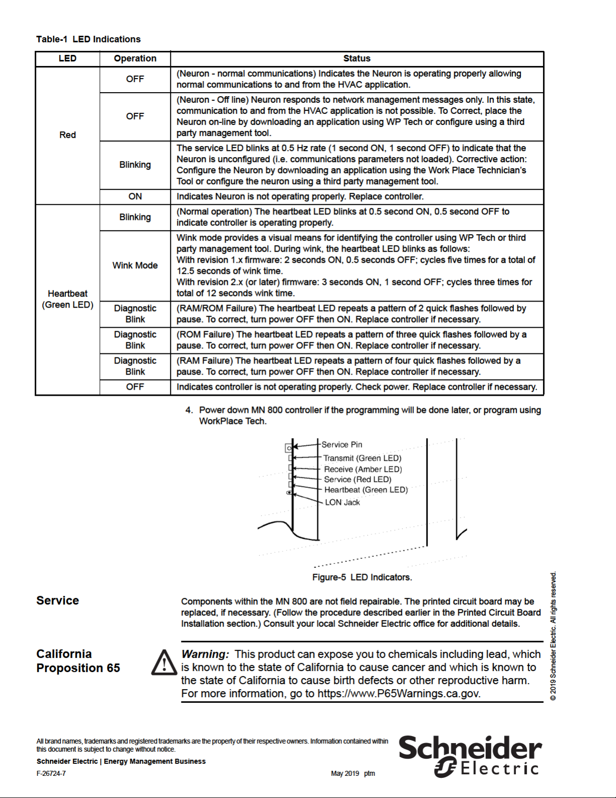
3. Check LED operation using Table-1.
Table-1 LED Indications
LED Operation Status
Normally ON indicating controller is powered and not actively transmitting data on the
LON.
Green
Amber
ON
Flashes OFF Flashes OFF while actively transmitting data on the LON.
OFF Normally OFF unless actively receiving data from the LON.
Flashes ON Flashes ON while actively receiving data from the LON.
Schneider Electric | Energy Management Business
Trademarks and registered trademarks are the property of their respective owners.
F-26724-7 7
© 2019 Schneider Electric. All rights reserved.
 Loading...