

Page 1
Application
The AV-7400 valve linkage kit is used to field assemble
MK-2690 pneumatic actuators to 1/2" through 2"
VB-7XXX series valve bodies.
Features
• Springs are provided for all control signal
applications, including 3 to 7, 5 to 10, and
8
to 13 psig.
AV-7400
Pneumatic Actuator Valve Linkage Kit
for VB-7XXX Series Valves
General Instructions
• Kit fits all VB-7XXX series valve bodies.
Applicable Literature
• Schneider Electric Environmental Controls Cross-
Reference Guide, F-23638
• Schneider Electric Environmental Controls
Reference Manual,
F-21683
• Schneider Electric Environmental Controls
Application Manual, F-21335
• Pneumatic Products Catalog, F-27383
• MK-2690 Pneumatic Valve Actuator General
Instructions, F-13893
• Schneider Electric Environmental Controls Valve
Selection Guide, F-26094
• EN-205 Water System Guidelines, F-26080
Printed in U.S.A. 6-10 Copyright 2010 Schneider Electric All Rights Reserved. F-26236-3
Page 2

INSTALLATION
C A U T I O N
C A U T I O N
Figure-1 Installation of Hexagon Coupler and Spring Compression Screw onto Valve Stem.
Spring
Compresion
Screw
Hexagon Coupler
Valve Stem
1/16" (1.6 mm)
Max.
Inspection
Requirements
Mounting
Inspect the package for damage. If damaged, notify the appropriate carrier immediately. If undamaged, open the package and inspect the device for obvious damage. Return any damaged products.
• Tools:
– Screwdriver appropriate for slotted spring compression screw (not provided)
– Linkage wrench (provided) or TOOL-20-1, packing and linkage wrench (not provided)
• Training: Installer must be a qualified, experienced technician
• Avoid locations where excessive moisture, corrosive fumes, or vibration are present. Do not
insulate piping above the actuator mounting nut preventing proper drainage.
• Install all two-way valves so that they close against the flow. An arrow on the valve body or
a tag indicates the proper flow direction.
• Always install three-way mixing valves with two inlets and one outlet.
• Always install three-way diverting valves with one inlet and two outlets.
• Do not install the actuator below the center line of the valve. For steam applications mount
the actuators above the valve body at 45° from vertical.
1. Actuators can be mounted in any upright position above the centerline of a valve body.
2. When selecting a location, allow sufficient room for accessories and for service of the product.
3. Maintain proper flow direction when installing all globe and radiator-type valves. Flow direction is indicated by an arrow on the valve body or by information on the attached tag.
Linkage Kit Installation
The AV-7400 linkage kit used with the MK-2690 actuator on VB-7XXX series valve bodies
requires no stem height setting. Refer to the Schneider Electric Environmental Controls
Valve Selection Guide, F-26094, for valves accommodating the MK-2690 actuator.
It is essential that the proper parts be used for the valve body on which the linkage is
being installed to ensure proper actuator operation and close off.
2 Copyright 2010 Schneider Electric All Rights Reserved. F-26236-3
Page 3

Procedure
C A U T I O N
Figure-2 Assembly of AV-7400 Linkage Kit onto VB-7XXX Series Valve.
Spring Retainer
Spring
Mounting Nut
Packing Nut
Spring
Compression
Screw
Hexagon Coupler
The linkage is assembled onto the VB-7XXX valve body with stem in the up position.
1. Thread the hexagon coupler onto the valve stem all the way to the bottom of the stem thread until it is finger-tight (Figure-1).
The hexagon coupler must reach to within 1/16" (1.6 mm) of the smooth section of the
stem to assure proper seating.
2. Start the spring compression screw one turn or more into the hexagon coupler. Pull the
valve stem completely up (
Figure-2).
3. Choose the correct spring for the desired actuator operating pressure range:
• Yellow spring — 3 to 7 psig (21 to 48 kPa)
• Black spring — 5 to 10 psig (34 to 68 kPa)
• Blue spring — 8 to 13 psig (55 to 89 kPa)
4. Slip the spring over the coupler and the spring compression screw.
5. Place the retainer over the screw. Twist the retainer 45° to lock it in place on the spring compression screw.
6. Insert the linkage wrench (supplied with kit, also included on TOOL-20-1) through the spring coils to hold the hexagon coupler.
7. Tighten the spring compression screw. To establish proper linkage height, run the
spring compression screw down until the screw end bottoms firmly on the stem top (Figure-3).
• On stem up closed valves (VB-722X) or three-way valves (VB-73XX), you can feel
the screw bottom.
• On stem up open valves (VB-721X), the stem and hexagon coupler begin to turn.
F-26236-3 Copyright 2010 Schneider Electric All Rights Reserved. 3
Page 4

MAINTENANCE
Figure-3 Installation of Linkage Spring.
Spring Retainer
(Turn 45 degrees to
lock in place.)
Wrench
(Hold to prevent turning.)
Spring
Screwdriver
2-1/8" (54 mm)—VB-721X
2-1/16" (52.4 mm)—VB-722X & VB-73XX
Turn until Spring Compression
Screw bottoms firmly on
valve stem.
Figure-4 MK-2690 Actuator Mounted on VB-7XXX Valve.
8. Confirm the stem height setting (Figure-3):
• 2-1/8" (54 mm) maximum after installation on stem up open valves (VB-721X).
• 2-1/16" (52.4 mm) maximum on stem up closed valves (VB-722X) or three-way
valves (VB-73XX).
9. Center the spring on top and bottom to assure smooth actuator operation.
10. Install the actuator onto the valve by screwing the actuator base onto the mounting nut
Figure-4). The actuator may be rotated as desired to facilitate making the pneumatic
(
connection.
The actuator linkage requires no maintenance.
Regular maintenance of the total system is recommended to assure sustained, optimum performance. Hard water leaves abrasive deposits and reduces component life. To maximize valve life, consult EN-205 Water System Guidelines, F-26080.
4 Copyright 2010 Schneider Electric All Rights Reserved. F-26236-3
Page 5

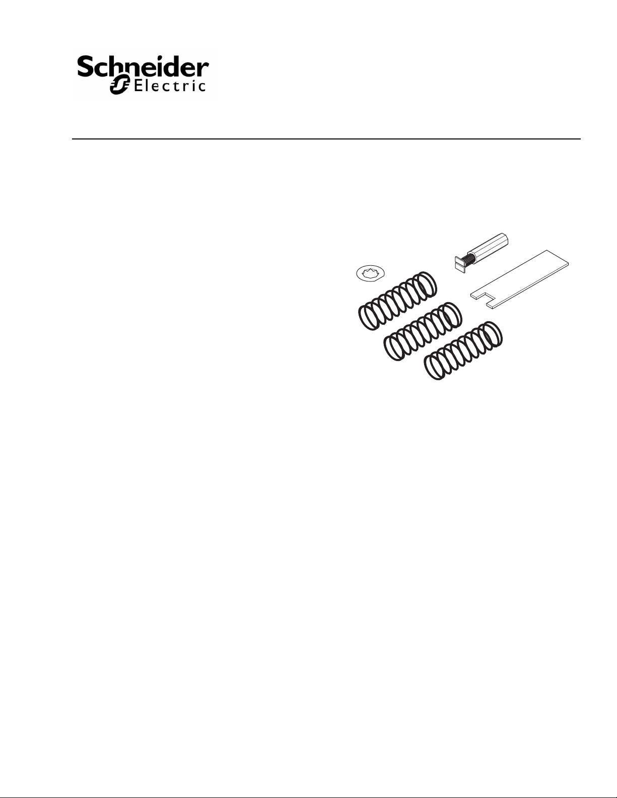
FIELD REPAIR
Figure-5 AV-7400 Pneumatic Actuator Valve Linkage Kit.
1
2
3
4
Individual parts of the actuator linkage are not repairable. Replace an inoperative actuator
linkage with a functional unit, or replace individual parts as necessary (Table-1 and
Figure-5).
Table-1 AV-7400 Replacement Parts.
Item
(See Figure-5)
1
2 YBA-559 Spring Retainer
3
4 NYBA-82 Linkage Wrench
Part No. Description
PNV-144-043 Yellow Spring for 3 to 7 psig (21 to 48 kPa)
PNV-145-045 Black Spring for 5 to 10 psig (34 to 68 kPa)
PNV-145-048 Blue Spring for 8 to 13 psig (55 to 89 kPa)
NYBA-80 Stem Coupler (hexagon)
NYBA-78 Spring Compression Screw
F-26236-3 Copyright 2010 Schneider Electric All Rights Reserved. 5
Page 6

6 Copyright 2010 Schneider Electric All Rights Reserved. F-26236-3
Page 7

F-26236-3 Copyright 2010 Schneider Electric All Rights Reserved. 7
Page 8

On October 1st, 2009, TAC became the Buildings business of its parent company Schneider Electric. This document reflects the visual identity of Schneider Electric,
however there remains references to TAC as a corporate brand in the body copy. As each document is updated, the body copy will be changed to reflect appropriate
corporate brand changes.
Copyright 2010, Schneider Electric
All brand names, trademarks and registered
trademarks are the property of their respective
owners. Information contained within this
document is subject to change without notice.
F-26236-3
 Loading...