

Application
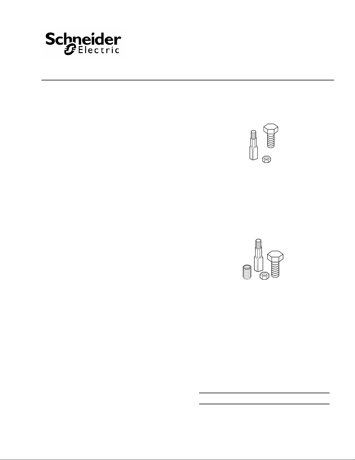
Note: Obsolete linkages are displayed in Figure-1.
The AV-644 series linkage kits are required for the assembly of MF and MS-2xxxx model actuators to valves.
The AV-644 linkage kit replaces the AV-643 linkage kit
h plastic stem extension for the assembly of MF and
wit
MS-223xx thermally isolated actuator models with
manufacture date codes prior to 9812.
The AV-644 linkage kit replaces all linkages for MF and
2xxxx actuators, including thermally isolated
MSmodels with manufacture date codes after 9832.
The AV-644-10 linkage kit replaces the AV-640 linkage
for all MF-221xx actuator models.
kit
AV-644 Series
Valve Linkage Kit
Installation Instructions
AV-644
Applicable Literature
• MS-22353 Proportional Valve Actuator General
Instr
uctions, F-26263
• MF-22xx3 Series Floating Valve Actuator General
Instr
uctions, F-26264
• MF-23xx3 Series High Output Force Floating Valve
Actuator General Instructions, F-26572
• Electric/Electronic Products Catalog, F-27382
AV-644-10
Printed in U.S.A. 6-10 Copyright 2010 Schneider Electric All Rights Reserved. F-26588-4
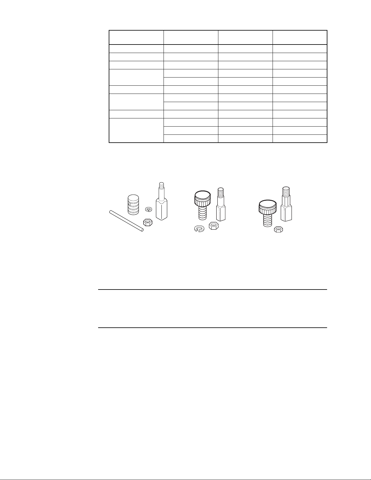
Table-1 Valve Linkage Conversion Chart.
AV-640 Obsolete
AV-643 Obsolete
(Plastic Stem Extension
AV-641 Obsolete
Figure-1 Obsolete Valve Linkage Kit Identification.
Actuator Part Number
MF-22103
MF-22123
b
b
Manufacturing Date
Code
All AV-6 40 AV-644-10
All AV-6 40 AV-644-10
Original LinkageaReplacement Linkage
MF-2x203 After 9832 AV-6 44 AV-644
MF-22303
Prior to 9812 AV-6 43 AV-644
9812 to 9832 AV-641 None
MF-2x303 After 9832 AV-6 44 AV-644
MF-22323
Prior to 9812 AV-6 43 AV-644
9812 to 9832 AV-641 None
MF-2x323 After 9832 AV-6 44 AV-644
Prior to 9812 AV-6 43 AV-644
MS-22353
9812 to 9832 AV-641 None
After 9832 AV-6 44 AV-644
a
Refer to Figure-1 for obsolete valve linkage kit identification.
b
Actuator drive screw is removable.
c
The brass stem extension threads are coated with nylon
d
Replacement linkage not available. Replace actuator
c
c
c
c
d
c
c
d
c
c
d
c
ASSEMBLY/ADJUSTMENT INSTRUCTIONS
Caution: Damage can occur if an actuator equipped with a potentiometer (seven wires) is run
or manually adjusted without being mounted to a valve. This causes the potentiometer output to
be out of specification and requires the actuator position to be re-established. If an actuator is
run or adjusted without being mounted to a valve, follow the “Re-establishing Potentiometer
Position” procedure on Page-11 before mounting the actuator to the valve.
2 Copyright 2010 Schneider Electric All Rights Reserved. F-26588-4
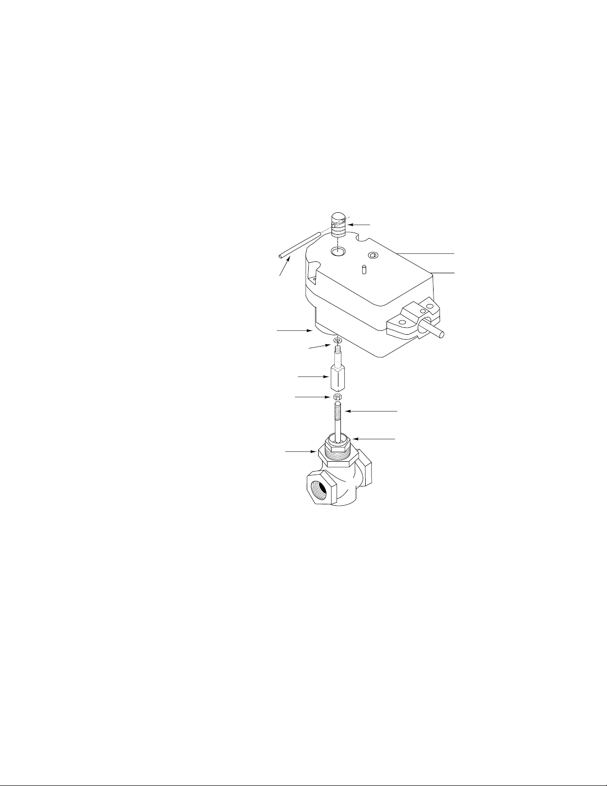
Actuator
Packing Nut
Valve Stem
Mounting Nut
Position Indicator Nut*
Locknut*
Lock Washer*
FRAC-209-1*
Included in AV-640
Valve Linkage Kit
Stem Extension*
Actuator/Valve
Mounting Opening
*
Manual Override Screw
(use 5/32" Allen wrench)
Manual Override Button
Figure-2 MF-221xx Series Actuator Valve Assembly with Obsolete AV-640 Linkage.
Assembly
The following models use round ID drive screws (confirm by removing the indicator nut and
looking at the center of the drive screw) that cannot be removed from the actuator.
Position the actuator above center line of valve to prevent damage from condensation and
dripping water.
Replacing AV-640 with AV-644-10 Valve Linkage on MF-221xx Actuators
1. Disconnect power from the actuator.
2. Verify actuator part number is of the MF-221xx series. The center of the drive screw and the center section of the stem extension should both be round.
3. Unscrew the position indicator nut on the top of the actuator and remove it. Insert FRAC-2091 pin through the hole in the position indicator nut and loosen by hand. Refer to Figure-2 for
part identification.
4. Unscrew the mounting nut from the actuator.
5. Remove the actuator from the valve. Lift the actuator to separate it from the valve and linkage.
6. Unscrew the stem extension and locknut to remove them from the valve stem.
7. Peel back the label on top of the actuator to expose the drive screw. Remove the drive screw from the actuator. Use a tapered pencil inserted in the center of the drive screw to unscrew it.
8. Discard the old position indicator nut, stem extension, lock washer, locknut, and drive screw.
F-26588-4 Copyright 2010 Schneider Electric All Rights Reserved. 3
9. Replace all the old parts with new parts from the AV-644-10 linkage kit in reverse order,
starting with the white plastic drive screw. Refer to
Figure-3.
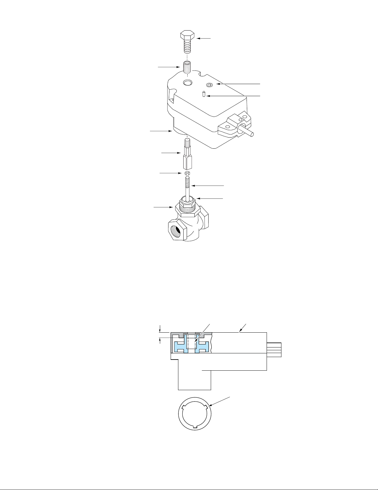
Packing Nut
Valve Stem
Position Indicator Nut*
Mounting Nut
Locknut*
Stem Extension*
Actuator/Valve
Mounting Opening
Available in AV-644-10
Valve Linkage Kit
*
Manual Override Screw
(use 5/32" Allen wrench)
Manual Override Button
Drive Screw*
Figure-3 MF-221xx Series Actuator Valve Assembly with AV-644 Linkage.
3/4" max.
(19 mm max.)
Drive Screw
Actuator Case
Do not block
drainage slots (3)
Figure-4 MF-221xx Actuator Drive Screw Position.
10. Insert the drive screw into the actuator. Insert a tapered pencil or pen into the drive screw and rotate.
11. Confirm that the drive screw for the MF-221xx actuator is mounted the required distance
from the top of the actuator case. See
Figure-4. If the drive screw is not in position, insert a
tapered pencil or pen into the drive screw and rotate.
4 Copyright 2010 Schneider Electric All Rights Reserved. F-26588-4

12. Position the valve stem in the down position. Place the locknut onto the valve stem.
Top of Packing Nut
Distance between top of
packing nut and stem
extension shoulder is
measured with valve
stem down.
1-3/32"
(27.8 mm)
AV-644-10 Valve Linkage
Figure-5 Stem Dimension Requirements for MF-221xx Series Actuators.
13. Screw the stem extension onto the valve stem. Adjust the stem extension to the height
specified for the selected actuator model. Refer to
Figure-5. This dimension is the distance
from the top of the packing nut to the shoulder of the stem extension.
14. Tighten the locknut against the stem extension to make the stem extension secure to the valve stem.
15. Insert the valve stem extension through the bottom of the actuator. If necessary, rotate the drive screw slightly to align the hex in the drive screw to the square in the lower bearing to match the stem extension hex and square.
16. Screw the valve mounting nut into the actuator and tighten.
17. Position the indicator nut on top of the actuator.
Caution: The hex shaped interface between the stem extension and drive screw does not
require high indicator nut tightening torque. Do not tighten the indicator nut beyond the hex
shoulder on the stem extension or a reduction in the actuator output may result. See Figure-10
for parts identification.
18. Tighten the indicator nut against the shoulder on the stem extension.
19. Reconnect power to the actuator.
F-26588-4 Copyright 2010 Schneider Electric All Rights Reserved. 5

Replacing AV-643 with AV-644 Valve Linkage on MF- and MS-22xx3 Actuators
Position indicator nut*
Manual override screw
(use 5/32" (4mm) Allen wrench)
Manual override button
Actuator/Valve
mounting opening
Optional FRAC-255
Metric Conduit Fitting
(Sold Separately)
Lock nut*
Valve Stem
Mounting nut
* Included in AV-643 Valve Linkage Kit.
Packing nut
AV-643 Stem extension*
(Plastic)
Figure-6 MF-22xx3 Series and MS-22353 Actuator Assembly Diagram with
Obsolete AV-643 Linkage.
1. Disconnect power from the actuator.
2. Remove the actuator from the valve. Unscrew the position indicator nut on the top of the actuator. Refer to Figure-6 for part identification.
3. Unscrew the valve mounting nut from the actuator.
4. Remove the actuator from the valve. Lift the actuator to separate it from the valve and linkage.
5. Unscrew the stem extension and locknut to remove them from the valve stem.
6. Discard the old position indicator nut, stem extension, and locknut.
7. Replace all the old parts with new part from the AV-644 linkage kit in reverse order, starting with the locknut and stem extension. Refer to Figure-7.
6 Copyright 2010 Schneider Electric All Rights Reserved. F-26588-4

Position indicator nut*
Manual override screw
(use 5/32" (4mm) Allen wrench)
Manual override button
Actuator/Valve
mounting opening
Stem extension*
(Hex Brass)
Lock nut*
Valve Stem
Mounting nut
* Available in Valve Linkage Kit AV-644
NO
TE: These parts are included with actuator.
Packing nut
Optional FRAC-255 Metric
Conduit Fitting
(Sold Separately)
Figure-7 MF-22xx3 Series and MS-22353 Actuator Assembly Diagram.
1-3/32"
(27.8 mm)
Top of Packing Nut
Distance between top of
packing nut and stem
extension shoulder is
measured with valve
stem down.
Figure-8 Valve and Stem Extension Assembly.
8. Position the valve stem in the down position. Place the locknut onto the valve.
9. Screw the stem extension onto the valve stem. Adjust the height of the stem extension to 13/32” (27.8 mm). This dimension is the distance from the top of the packing nut to the
shoulder of the stem extension. Refer to Figure-8 and the General Instructions for the
actuator. See Applicable Literature on Page-1.
10. Tighten the locknut against the stem extension to make the stem extension secure to the valve stem.
11. Position the valve stem in the down position.
F-26588-4 Copyright 2010 Schneider Electric All Rights Reserved. 7

12. Confirm that the drive screw is at the required distance from the top of the actuator case.
Actuator caseDrive screw
55/64"
(22 mm)
to top of
drive screw
MS-22353
Figure-9 Position Drive Screw Before Mounting Actuator.
See Figure-9. If the drive screw is not in position, insert a tapered pencil or pen into the drive
screw and rotate.
13. Insert the valve stem extension through the bottom of the actuator. If necessary, rotate the drive screw slightly to align the hex in the drive screw to the square in the lower bearing to match the stem extension hex and square.
14. Screw the valve mounting nut into the actuator and tighten.
Caution: The hex shaped interface between the stem extension and drive screw does not
require high indicator nut tightening torque. Do not tighten the indicator nut beyond the hex
shoulder on the stem extension or a reduction in the actuator output may result. See
Figure-10
for parts identification.
15. Insert the position indicator nut into the hole at the top of the actuator. Screw it onto the stem extension and tighten it against the shoulder on the stem extension.
16. Reconnect power to the actuator.
8 Copyright 2010 Schneider Electric All Rights Reserved. F-26588-4

AV-644 Valve Assembly
Position indicator nut*
Manual override screw
(use 5/32" (4mm) Allen wrench)
Manual override button
Actuator/Valve
mounting opening
Stem extension*
Lock nut*
Valve Stem
Mounting nut
* Available in Valve Linkage Kit AV-644
NO
TE: These parts are included with actuator.
Packing nut
Optional FRAC-255 Metric
Conduit Fitting
(Sold Separately)
Figure-10 MF-2xxx3 Series and MS-22353 Actuator Assembly Diagram.
1-3/32"
(27.8 mm)
Top of Packing Nut
Distance between top of
packing nut and stem
extension shoulder is
measured with valve
stem down.
AV-644
Required Stem Dimensions for
MF-2XXX3 Actuators.
Figure-11 Valve and Stem Extension Assembly.
1. Position the valve stem in the down position. Place the locknut onto the valve stem.
2. Remove the stem extension from the actuator. Unscrew the position indicator nut on the top of the actuator and remove it. Refer to Figure-10 for part identification.
3. Screw the locknut and stem extension onto the v
selected actuator to the height specified for that model, see Figure-11. This dimension is the
distance from the top of the packing nut to be shou
4. Tighten the locknut against the stem
valve stem.
5. Position the valve stem so it is seated in the down position.
alve stem. Adjust the stem extension of the
lder of the stem extension.
extension to make the stem extension secure to the
F-26588-4 Copyright 2010 Schneider Electric All Rights Reserved. 9

6. Confirm that the drive screw for the actuator model being mounted is the required distance
Figure-12 Position Drive Screw Before Mounting Actuator.
Actuator case
55/64"
(22 mm)
to top of
drive screw
Drive screw
Do not block drainage slots.
MF-2X203
Hot Water Actuator
or
Actuator case
Drive screw
55/64"
(22 mm)
to top of
drive screw
MF-2X3X3
Chilled/Hot Water Actuator
from the top of the actuator case. See Figure-12. If the drive screw is not in position, insert
a tapered pencil or pen into the drive screw and rotate.
7. Insert the valve stem extension through the bottom
of the actuator. Rotate the actuator
slightly until the stem extension slides through the actuator, and then rotate to the desired
position for wiring.
Note: If necessary rotate the drive screw slightly to align the hex in the drive screw to the
square in the bearing to match the stem extension.
8. Screw the valve mounting nut into the actuator and tighten.
9. Position the indicator nut on top on the actuator.
10. Tighten the indicator nut against the should
er of the hex on the stem extension.
Caution: The hex shaped interface between the stem extension and drive screw does not
require high indicator nut tightening torque. Do not tighten the indicator nut beyond the hex
shoulder on the stem extension or a reduction in the actuator output may result. See Figure-10
for parts identification.
11. Reconnect power to the actuator.
10 Copyright 2010 Schneider Electric All Rights Reserved. F-26588-4

Re-establishing Potentiometer Position
If an actuator is run or adjusted without being mounted to a valve, the actuator position can be
re-established. Refer to Ta bl e - 2 and Figure-10.
1. Remove actuator position indicator nut. Unscrew mounting nut and remove actuator from valve.
2. Apply a fixed DC voltage (30V maximum) across the potentiometer with positive voltage applied to extend [Brown] and 0 volts to retract [Orange].
3. Depress the manual override button and turn the manual override screw so that the
potentiometer output is 91.5%. For example, with 10V applied across the potentiometer
adjust the actuator so the potentiometer output is 9.15V from wiper [Blue] to retract [Orange].
Now follow the assembly steps for the appropriate valve linkage.
Table-2 Power and Control Wiring Color Codes.
Actuator
Label
Actuator
Power
Proportional
ontrol
C
Signals
Feedback
ontrol
C
Signal
a
Actuator models manufactured prior to date code 991x (e.g. 9910, 9911, etc.) have multi-color, numbered wires.
b
Actuator power wire may be Violet on some models.
Earth Earth Ground Green Green (—)
24 H 24 Vac Black Black (1)
24 G 24 Vac Red Red
+VDC (IN) 2 to 10 Vdc Input White White/Green (3)
-COMMON DC Common Ground Orange White/Orange (4)
+mADC (IN) 4 to 20 mADC Input Brown White/Brown (6)
+VFB Actuator Feedback Blue White/Blue (5)
Description
Color Only
(Current Models)
Wire Codes
Color with Numbers
(Older Models)
b
(2)
a
F-26588-4 Copyright 2010 Schneider Electric All Rights Reserved. 11

On
October 1st, 2009, TAC became the Buildings business of its parent company Schneider Electric. This document reflects the visual identity of Schneider Electric,
however there remains references to TAC as a corporate brand in the body copy. As each document is updated, the body copy will be changed to reflect appropriate
corporate brand changes.
Copyright 2010, Schneider Electric
All brand names, trademarks and registered
trademarks are the property of their respective
owners. Information contained within this
document is subject to change without notice.
F-26588-4
 Loading...