

Schneider Electric atv71lift communication parameters [EN]
2354235 11/2008
Altivar LIFT
Variable speed drive
for synchronous and asynchronous lift motors
Communication parameters
Software V5.4
11/2011
BBV19480
www.schneider-electric.com

Contents
Presentation _________________________________________________________________________________________________ 4
Document structure and directions for use__________________________________________________________________________ 6
Description of parameters_______________________________ ________________________________________________________ 7
Drive terminal displays ___________________________________________________________________________________ 7
Profiles _____________________________________________________________________________________________________ 8
What is a profile? _______________________________________________________________________________________ 8
Functional profiles supported by the Altivar LIFT ______________________________________________________________ 9
I/O profile __________________________________________________________________________________________________ 10
Definition ____________________________________________________________________________________________ 10
Control word - run on state [2 wire] (2C) ____________________________________________________________________ 12
Control word - run on edge [3 wire] (3C) ___________________________________________________________________ 13
Status word (ETA) _____________________________________________________________________________________ 14
CiA402 profile_______________________________________________________________________________________________ 15
Functional description __________________________________________________________________________________ 15
CiA402 state chart _____________________________________________________________________________________ 16
Description of states ___________________________________________________________________________________ 17
Control word (CMD) ____________________________________________________________________________________ 19
Status word (ETA) _____________________________________________________________________________________ 21
Starting sequence _____________________________________________________________________________________ 22
Sequence for a drive powered by the power section line supply __________________________________________________ 23
Sequence for a drive with separate control section ____________________________________________________________ 25
Sequence for a drive with line contactor control ______________________________________________________________ 28
Command/reference switching__________________________________________________________________________________ 31
Channels ____________________________________________________________________________________________ 31
Not separate mode ____________________________________________________________________________________ 32
Separate mode _______________________________________________________________________________________ 32
Switching in not separate mode ___________________________________________________________________________ 33
Switching in separate mode ____________________________________ __________________________________________ 33
Channel switching _____________________________________________________________________________________ 34
Reference switching principle ____________________________________________________________________________ 36
Command switching principle ____________________________________________________________________________ 37
Assigning control word bits ______________________________________________________________________________ 38
Copy on switching _____________________________________________________________________________________ 41
Forced local ________________________________________________________________________________________________ 42
Definition ____________________________________________________________________________________________ 42
Forced local mode and reference switching _________________________________________________________________ 43
Forced local mode and command switching _________________________________________________________________ 44
Priority stops________________________________________________________________________________________________ 46
Priority stops on the graphic display terminal ________________________________________________________________ 46
Priority stops via the terminals or the network ________________________________________________________________ 46
Communication monitoring_____________________________________________________________________________________ 48
Principle _____________________________________________________________________________________________ 48
Network monitoring criteria ______________________________________________________________________________ 48
Behavior in the event of a network fault _____________________________________________________________________ 49
Detailed operation _____________________________________________________________________________________ 50
Assignment of setpoints from a network___________________________________________________________________________ 52
Setpoint parameters ___________________________________________________________________________________ 52
Configuration saving and switching _____________________________________________________________ _________________ 54
Saving the configuration ________________________________________________________________________________ 54
Restore configuration ___________________________________________________________________________________ 56
Configuration switching via control word ____________________________________________________________________ 57
Configuration switching by selection _______________________________________________________________________ 61
Parameter set switching_______ ___________________________________________________ _____________________________ 63
Loading drive parameters______________________________________________________________________________________ 68
Requirement _________________________________________________________________________________________ 68
Procedure ___________________________________________________________________________________________ 68
Command parameters ________________________________________________________________________________________ 70
Setpoint parameters__________________________________________________________________________________________ 73
Status parameters ___________________________________________________________________________________________ 75
Output value parameters ______________________________________________________________________________________ 83
Output values (speed) __________________________________________________________________________________ 83
Output values (torque) ________________________________________ __________________________________________ 84
Output values (motor) __________________________________________________________________________________ 85
Reference parameters ________________________________________________________________________________________ 87
References (speed) ____________________________________________________________________________________ 87
References (torque) ____________________________________________________________________________ ________ 88
Measurement parameters______________________________________________________________________________________ 89
Input measurements ______________________________________________________ _____________________________ 89
BBV19480 11/2011 2

Contents
Thermal states ________________________________________________________________________________________ 89
Time ________________________________________________________________________________________________ 90
I/O parameters ______________________________________________________________________________________________ 92
Logic I/O ____________________________________________________________________________________________ 92
Analog inputs _________________________________________________________________________________________ 93
Analog outputs ________________________________________________________________________________________ 94
Encoder _____________________________________________________________________________________________ 95
Fault parameters_____________________________________________________________________________________________ 96
Log parameters_____________________________________________________________________________________________ 103
Log of the following faults ______________________________________________________________________________ 107
Identification parameters _____________________________________________________________________________________ 111
CiA402 standard configuration and adjustment parameters_______________________________________________ ____________ 114
ODVA standard configuration and adjustment parameters ___________________________________________________________ 118
Index of parameter codes_____________________________________________________________________________________ 119
3 BBV19480 11/2011
Presentation
2
1
3
1
2
1
3
Magelis XBT Premium
FTM FTM
ATV 31
ATV 71L
Sensors Sensors
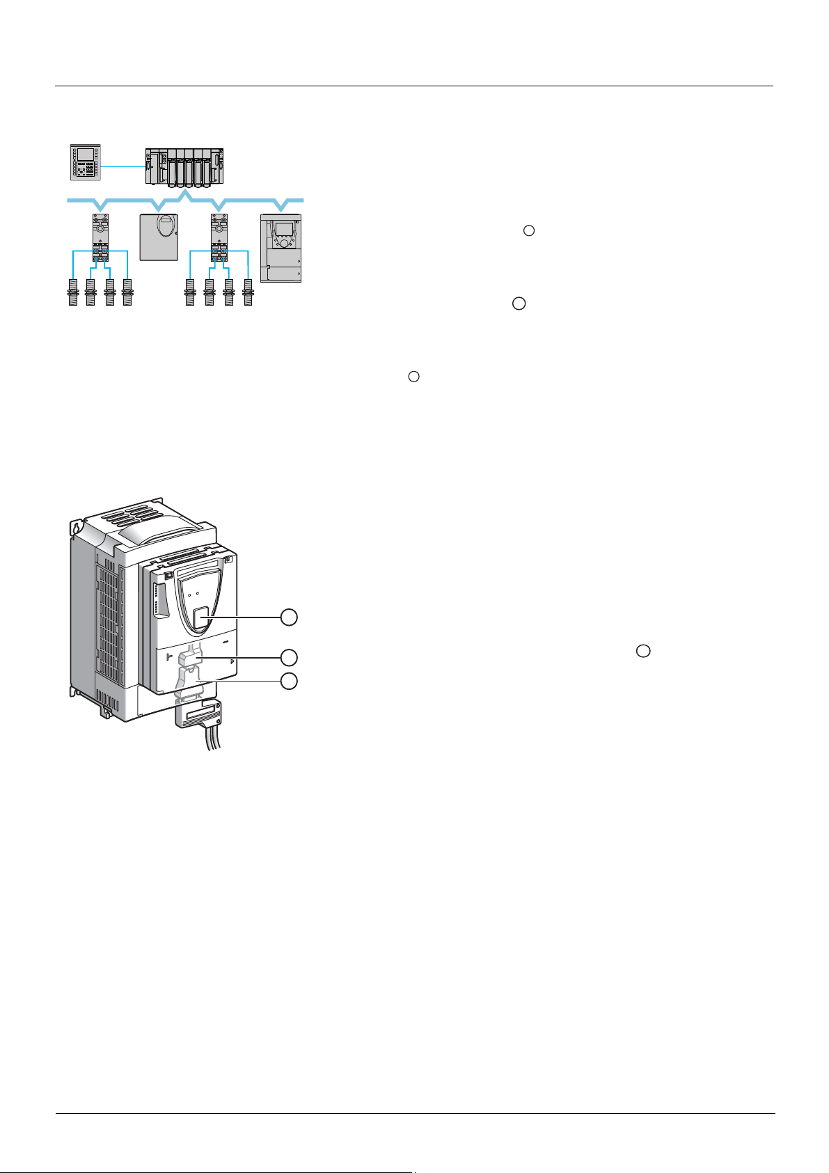
Example of configuration on the CANopen bus
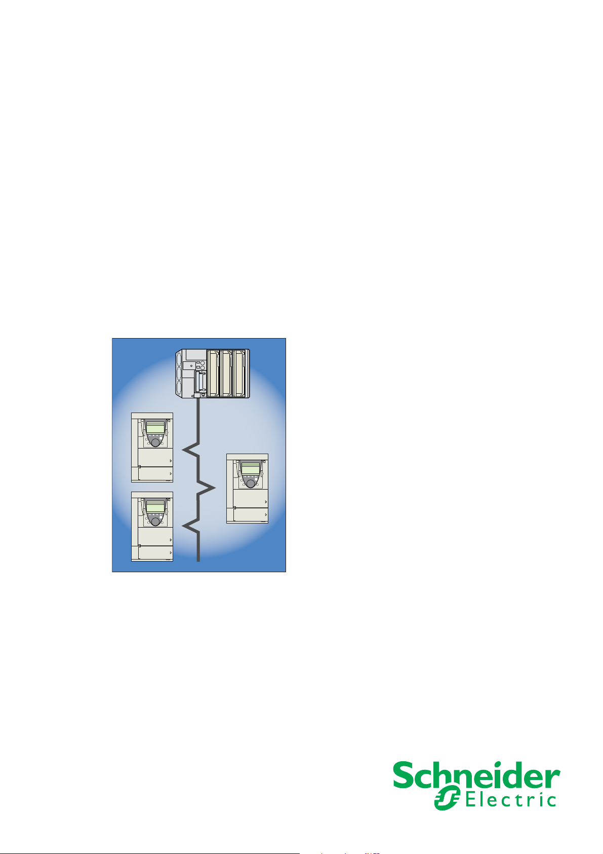
The Altivar LIFT drive has been designed to meet all the configuration requirements
encountered within the context of industrial communication installations.
It includes Modbus and CANopen communication protocols as standard.
Two integrated communication ports enable direct access to the Modbus protocol :
• One RJ45 Modbus connector port , located on the drive front panel,
which is used to connect:
• The remote graphic display terminal
• A Magelis industrial HMI terminal
• The PC-Software workshop
• One RJ45 Modbus network port , located on the drive’s control terminals,
which is dedicated to control and signaling by a PLC or other type of controller.
It can also be used to connect a display terminal or the PC-Software workshop.
The CANopen protocol can be accessed from the Modbus network port via the
CANopen adapter
(1).
The Altivar LIFT can also be connected to other networks and indu strial communication
buses by using one of the communication option cards:
• Ethernet TCP/IP
• Modbus/Uni-Telway. This card provides access to additional functions, which
complement those of the integrated ports: Modbus ASCII and 4-wire RS 485
•Fipio
• Modbus Plus
•Profibus DP
• DeviceNet
•INTERBUS
• etc. (Please refer to the catalog)
The control section can be powered separately, thus allowing communication
(monitoring, diagnostics) to be maintained even if the power supply section fails.
(1) If the CANopen adapter is installed, Modbus will not be available on the network port .
4 BBV19480 11/2011

Presentation
All the drive functions are accessible via the network:
• Control
• Monitoring
• Adjustment
• Configuration
If the "Controller Inside" programmable card is installe d on the drive , it s variables (%MW, etc.) can be acce ssed via the integ rated Modb us
ports or the Ethernet option card.
The speed/torque command and reference can come from different sources:
• The I/O terminals
• The communication ne twork
• The "Controller Inside" programmable card
• The remote graphic display terminal
• The PC-Software workshop (for commissioning and maintenance)
The Altivar LIFT drive's advanced functions can be used to manage switching of these command and reference sources according to
application requirements.
The periodic communication variables can be selected via:
• The network configuration software (Sycon, etc.): CANopen, DeviceNet
• The Altivar LIFT’s communication scanner function: Profibus DP, Fipio, Modbus Plus
• The network's IO Scanner function: Ethernet TCP/IP
With the exception of DeviceNet, regardless of network type, the Altivar LIFT can be controlled:
• In accordance with the Drivecom profile (CANopen CiA DSP 402)
• In accordance with the I/O profile, whereby control is as straightforward and flexible as control via the I/O terminals
The DeviceNet card supports the ODVA standard profile.
Communication is monitored according to criteria specific to each protocol. Regardless of protocol type, the reaction of the drive to a
communication fault can be configured:
• Drive fault involving: Freewheel stop, stop on ramp, fast stop or braked stop
• Stop without drive fault
• Maintain the last command received
• Fallback position at a predefined speed
• Ignore the fault
A command from the CANopen bus is handled with the same priority as an input from the drive termi nals. This enables very good response
times to be achieved on the network port via the CANopen adapter.
BBV19480 11/2010 5

Document structure and directions for use
Installation Manual
This manual describes:
• Assembly
• How to connect the drive
Programming Manual
This manual describes:
• Functions
• Parameters
• How to use the drive's display terminal (integrated display terminal and graphi c display terminal)
Communication Parameters Manual
This manual describes:
• The operating modes specific to communication (state chart)
• The interaction between communication and local control
• The control, reference and monitoring parameters, with specific information for use via a bus or communication network
It does not include the drive adjustment and configuration parameters, which are contained in the Excel file supplied as an
appendix to this manual.
All the parameters are grouped together in an Excel file supplied as an appendix, with the following data:
-Code
-Name
- Addresses: logic, CANopen®, INTERBUS, Device Net
- Category
- Read/write access
- Type: signed numerical, unsigned numerical, etc.
-Unit
- Factory setting
- Minimum value
- Maximum value
- Display on the graphic display terminal and the 7-segment integrated display terminal
- Relevant menu
This file offers the option of sorting and arranging the data according to any criterion chosen by the user.
Data relating to operation, interdependences and limits of use are described in the Programming Manual.
The various documents are to be used as follows:
1. For information about the drive and its programming, refer to the Programming Manual.
2. For information about communication and it s programming, refer to the Parameters Manual.
3. Use the Parameters file to define any addresses and values of the adj ustment and configuration parameters to be modified through
communication.
The section entitled "Loading drive parameters" on page 68 describes the recommended procedure for loading parameters
through communication.
Modbus®, CANopen®, Ethernet™, Profibus®, INTERBUS, Uni-Telway, FIPIO™, Modbus Plus and Device
Net manuals
These manuals describe:
• Assembly
• Connection to the bus or network
• Diagnostics
• Configuration of the communication-specific parameters via the integrated display terminal or graphic display terminal
They describe the protocol communication services in detail.
"Controller Inside" Manual
This manual describes, for the "Controller Inside" card:
• Assembly
• Connection
• Functions
• Configuration
BBV19480 11/2011 6

Description of parameters
Identification
A parameter is defined by means of various character strings:
• Code: 4 charac
brt, tLIG
• Name: Description in plain text (used by the PC-Software workshop)
• Terminal name: Character string in square brackets for the graphic display terminal [Gen. torque lim]
Addresses
There are 4 formats for specifying parameter addresses:
• Logic address: Address for the Modbus messaging (RS485 and Ethernet TCI/IP) and the PKW indexed periodic variables (Fipio,
Profibus DP), in decimal and hexadecimal (preceded by 16#).
To optimize Modbus messaging performance, two addresses are given for the control word and the status word. The addresses
annotated "speed" are for use in rpm; the addresses annotated "frequency" are for use in Hz.
• CANopen index: CANopen index/subindex in hexadecimal fo rmat, to be used for va riabl e assign ment of PDOs and SDO messagi ng
• INTERBUS index: Index/subindex in hexadecimal for PCP messaging
• DeviceNet path: Class/instance/attribute in hexadecimal
Read/write
• R: Read only
• R/W: Read and write
• R/WS: Read and write, but write only possible when motor is at standstill
ters max. The code makes it possible to identify the parameter on the integrated 7-segment display terminal (Examples:
)
Type
• WORD (bit register): Word where each bit represents an item of command, monitoring or configuration information
• WORD (listing): Word where each value represents a possible choice for a configuration or state
• INT: Signed integer
• UINT: Unsigned integer
• DINT: Signed double integer
• UDINT: Unsigned double integer
Format
Hexadecimal values are written as follows: 16#pppp
Drive terminal displays
The menus that appear on the graphic display terminal are shown in square brackets.
Example: [1.9 COMMUNICATION].
The menus that appear on the integrated 7-segment display terminal always end with a dash and appear between round brackets.
Example: (COM-).
Parameter names are displayed on the remote graphic display terminal in square brackets.
Example: [Fallback speed].
The parameter codes displayed on the integrated 7-segment display terminal are shown in round brackets.
Example: (LFF).
7 BBV19480 11/2011

Profiles
What is a profile?
There are three types of profile:
• Communication profiles
• Functional profiles
• Application profiles
Communication profiles
A communication profile describes the characteristics of the bus or network:
• Cables
• Connectors
• Electrical characteristics
• Access protocol
• Addressing system
• Periodic exchange service
• Messaging service
•...
A communication profile is unique to a type of network (Fipio, Profibus DP, etc.) and is used by various different types of device.
Functional profiles
A functional profile describes the behavior of a type of device. It defines:
• Functions
• Parameters (name, format, unit, type, etc.)
• Periodic I/O variables
• State chart(s)
•...
A functional profile is common to all members of a device family (variable speed drives, encoders, I/O modules, displays, etc.).
Ideally, functional profiles should be network-independent, but in reality they are not. They can feature common or similar parts. The
standardized (IEC 61800-7) functional profiles of variable speed drives are:
• CiA402
• PROFIDRIVE
•CIP
DRIVECOM has been available since 1991.
CiA402 "Device profile for drives and motion control" represents the next stage of this standard’s development and is maintained by
Can
In Automation.
Some protocols also support the ODVA (Open DeviceNet Vendor Association) profile.
Application profiles
Application profiles define in their entirety the services to be provided by the devices on a machine. For example, "CiA DSP 417-2 V 1.01
part 2: CANopen application profile for lift control systems - virtual device definitions".
Interchangeability
The aim of communication and functional profiles is to achieve interchangeability of the devices connected via the network.
Although this aim is not always achieved, the profiles facilitate free competition.
BBV19480 11/2011 8

Profiles
Functional profiles supported by the Altivar LIFT
I/O profile
Using the I/O profile simplifies PLC programming.
When controlling via the terminals or the display terminal, the I/O profile is used without knowing it.
With an Altivar LIFT, the I/O profile can also be used when controlling via a network.
The drive starts up as soon as the run command is sent.
The 16 bits of the control word can be assigned to a function or a terminal input.
This profile can be developed for simultaneous control of the drive via:
• The terminals
• The Modbus control word
• The CANopen control word
• The network card control word
• The "Controller Inside" control word
The I/O profile is supported by the drive itself and therefore in turn by all the communication ports (integrated Modbus, CANopen and the
Ethernet, Fipio, ModbusPlus, Modbus, Uni-Telway, Profibus DP, DeviceNet, and INTERBUS communication cards).
CiA402 profile
The drive only starts up following a command sequence.
The control word is standardized.
5 bits of the control word (bits 11 to 15) can be assigned to a function or a terminal input.
The CiA402 profile is supported by the drive itself and therefore in turn by all the communication ports (integrated Modbus, CANopen and
the Ethernet, Fipio, ModbusPlus, Modbus, Uni-Telway, Profibus DP, DeviceNet, and INTERBUS communication cards).
The Altivar LIFT supports the CiA402 profile’s "Velocity mode".
In the CiA402 profile, there are two modes that are specific to the Altivar LIFT and chara cterize command and reference manageme nt (see
section
“Command/reference switching”, page 31):
• Separate mode [Separate] (SEP)
• Not separate mode [Not separ.] (SIM)
ODVA profile
The drive starts up as soon as the run command is sent.
The control word is standardized.
The ODVA profile is supported by the DeviceNet communication card.
9 BBV19480 11/2011
I/O profile
C201
C202
bit 9
bit 8
bit 7
bit 6
bit 5
bit 4
bit 3
bit 2
bit 1
bit 0
bit 2
bit 1
bit 0
bit 11
bit 10
bit 13
bit 12
bit 15
bit 14
A
B
CANopen control word
Function
C201
C202
bit 9
bit 8
bit 7
bit 6
bit 5
bit 4
bit 3
bit 2
bit 1
bit 0
bit 2
bit 1
bit 0
bit 11
bit 10
bit 13
bit 12
bit 15
bit 14
A
B
LI2
LI10
LI9
LI8
LI7
LI6
LI5
LI4
LI3
LI2
LI1
LI12
LI11
LI14
LI13
C
CANopen control word
Terminals
Function
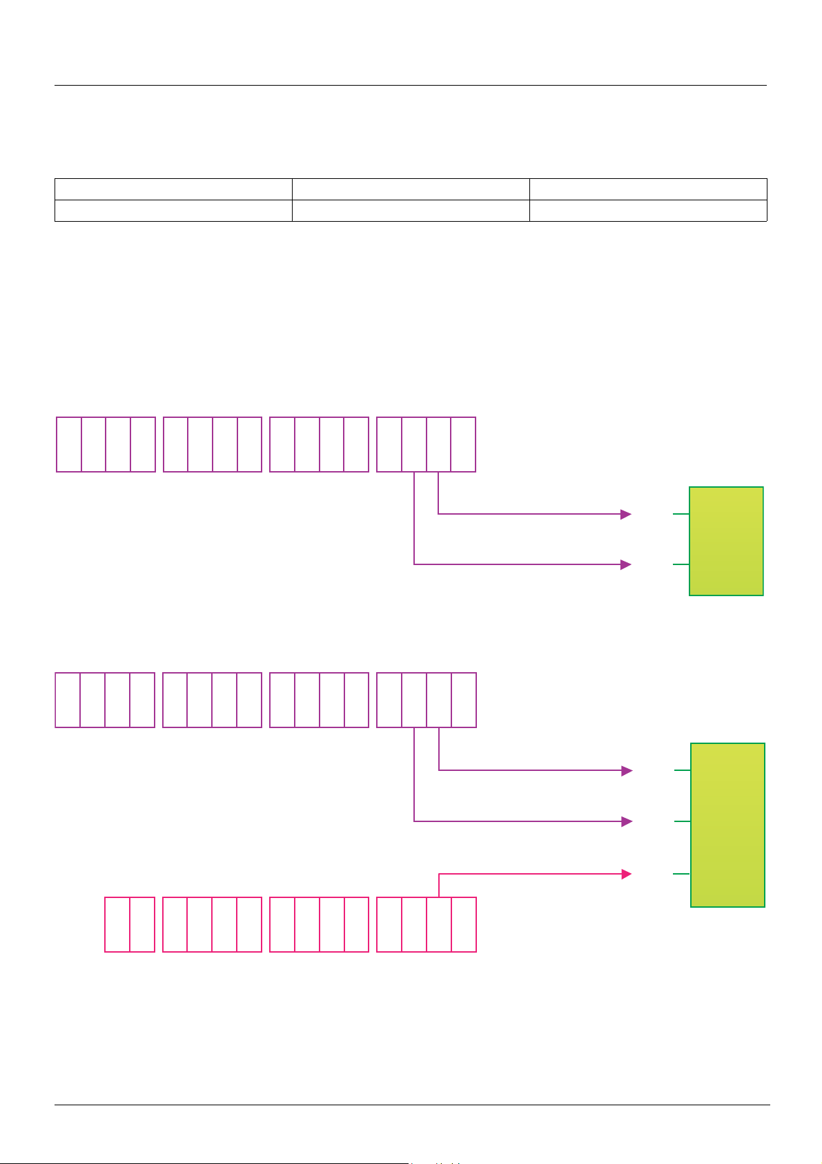
Definition
The behavior of the drive is identical whether via the network or via the terminals.
The I/O profile is achieved via the following configuration:
Menu Parameter Value
[1.6 - COMMAND] (CtL-) [Profile] (CHCF) [I/O profile] (IO)
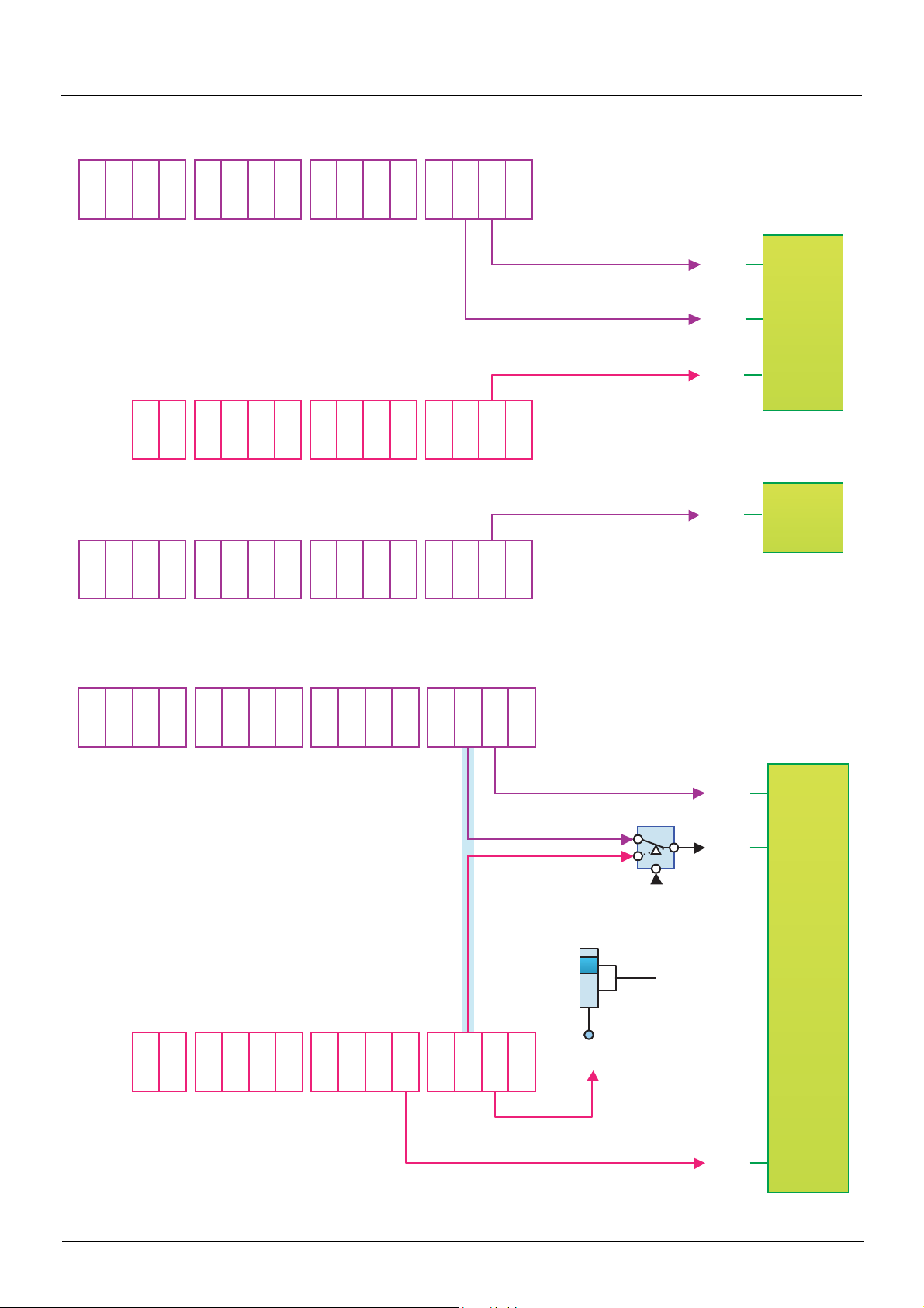
As well as to logic inputs of the terminals, drive functio n s can be assigned to control word bits.
A function input can be assigned to:
• A terminal input (LI2 to LI14)
• A Modbus control word bit (C101 to C115)
• A CANopen control word bit (C201 to C215)
• A network card control word bit (C301 to C315)
• A Controller Inside control word bit (C401 to C415)
• A switched bit (Cd00 to Cd15): See "Command/reference switching" section.
Schematic diagrams:
Fixed assignment on CANopen:
Fixed assignment to terminals and on CANopen: :
BBV19480 11/2011 10
I/O profile
C201
C202
C401
bit 9
bit 8
bit 7
bit 6
bit 5
bit 4
bit 3
bit 2
bit 1
bit 0
bit 2
bit 1
bit 0
bit 11
bit 10
bit 13
bit 12
bit 15
bit 14
bit 9
bit 8
bit 7
bit 6
bit 5
bit 4
bit 3
bit 2
bit 1
bit 0
bit 2
bit 1
bit 0
bit 11
bit 10
bit 13
bit 12
bit 15
bit 14
A
B
LI2
LI10
LI9
LI8
LI7
LI6
LI5
LI4
LI3
LI2
LI1
LI12
LI11
LI14
LI13
C
Stop
CANopen control word
Terminals
Function
"Controller Inside" control word
Fast stop
C201
Cd02
LI5
LI10
LI9
LI8
LI7
LI6
LI5
LI4
LI3
LI2
LI1
LI12
LI11
LI14
LI13
bit 9
bit 8
bit 7
bit 6
bit 5
bit 4
bit 3
bit 2
bit 1
bit 0
bit 2
bit 1
bit 0
bit 11
bit 10
bit 13
bit 12
bit 15
bit 14
LI2
A
B
C
CANopen control word
Terminals
Function
CANopen
Terminals
Command
switching
CCS
Fixed assignment to terminals, on CANopen and on "Controller Inside" card:
Fixed assignment to terminals and on CANopen with command switching :
11 BBV19480 11/2011

I/O profile
Control word - run on state [2 wire] (2C)
Please refer to the [1.5 INPUTS / OUTPUTS CFG] (I-O-) section of the Programming Manual.
The forward run command is automatically assigned to input LI1 and to bit 0 of the various control wo rds.
This assignment cannot be modified.
The run command is active on state 1:
• Of input LI1, if the terminals are active
• Of bit 0 of the control word, if the network is active
Bits 1 to 15 of the control words can be assigned to drive functions.
bit 7 bit 6 bit 5 bit 4 bit 3 bit 2 bit 1 bit 0
Configurable Configurable Configurable Configurable Configurable Configurable Configurable Forward
bit 15 bit 14 bit 13 bit 12 bit 11 bit 10 bit 9 bit 8
Configurable Configurable Configurable Configurable Configurable Configurable Configurable Configurable
In the case of a [2 wire] (2C) run on state command and I/O profile, fixed assignment of a function input is possible using the following
codes:
Fixed assignments
Bit
bit 0 Forward
bit 1 LI2 - - C101 C201 C301 C401
bit 2 LI3 - - C102 C202 C302 C402
bit 3 LI4 - - C103 C203 C303 C403
bit 4 LI5 - - C104 C204 C304 C404
bit 5 LI6 - - C105 C205 C305 C405
bit 6 - LI7 - C106 C206 C306 C406
bit 7 - LI8 - C107 C207 C307 C407
bit 8 - LI9 - C108 C208 C308 C408
bit 9 - LI10 - C109 C209 C309 C409
bit10 - - LI11 C110 C210 C310 C410
bit11 - - LI12 C111 C211 C311 C411
bit12 - - LI13 C112 C212 C312 C412
bit13 - - LI14 C113 C213 C313 C413
bit14 - - - C114 C214 C314 C414
bit15 - - - C115 C215 C315 C415
Drive
terminals
Logic I/O
card
Extended I/O
card
Modbus CANopen Network card
"Controller Inside"
card
For example, to assign the operating direction command to bit 1 of CANopen, simply conf igure the [Reverse ass ign.] (rrS) parameter with
the value [C201] (C201).
BBV19480 11/2011 12

I/O profile
Control word - run on edge [3 wire] (3C)
Please refer to the [1.5 INPUTS / OUTPUTS CFG] (I-O-) section of the Programming Manual.
The stop command is automatically assigned to input LI1 and to bit 0 of the control words.
This assignment cannot be modified.
This command enables running on state 1:
• Of input LI1, if the terminals are active
• Of bit 0 of the control word, if the network is active
The forward run command is automatically assigned to input LI2 and to bit 1 of the control words.
This assignment cannot be modified.
The forward run command is active if the stop command is at 1 and on a rising edge (0 V 1):
• Of input LI2, if the terminals are active
• Of bit 1 of the control word, if the network is active
Bits 2 to 15 of the control words can be assigned to drive functions.
bit 7 bit 6 bit 5 bit 4 bit 3 bit 2 bit 1 bit 0
Configurable Configurable Configurable Configurable Configurable Configurable Forward Stop
bit 15 bit 14 bit 13 bit 12 bit 11 bit 10 bit 9 bit 8
Configurable Configurable Configurable Configurable Configurable Configurable Configurable Configurable
In the case of a [3 wire] (3C) run on state command and I/O profile, fixed assignment of a function input is possible using the following
codes:
Fixed assignments
Bit
bit 0 Authorization to run (Stop)
bit 1 Forward
bit 2 LI3 - - C102 C202 C302 C402
bit 3 LI4 - - C103 C203 C303 C403
bit 4 LI5 - - C104 C204 C304 C404
bit 5 LI6 - - C105 C205 C305 C405
bit 6 - LI7 - C106 C206 C306 C406
bit 7 - LI8 - C107 C207 C307 C407
bit 8 - LI9 - C108 C208 C308 C408
bit 9 - LI10 - C109 C209 C309 C409
bit10 - - LI11 C110 C210 C310 C410
bit11 - - LI12 C111 C211 C311 C411
bit12 - - LI13 C112 C212 C312 C412
bit13 - - LI14 C113 C213 C313 C413
bit14 - - - C114 C214 C314 C414
bit15 - - - C115 C215 C315 C415
Drive
terminals
Logic I/O
card
Extended
I/O card
Modbus CANopen Network card
"Controller Inside"
card
For example, to assign the operating direction command to bit 2 of CANopen, simply conf igure the [Reverse ass ign.] (rrS) parameter with
the value [C202] (C202).
13 BBV19480 11/2011

I/O profile
Status word (ETA)
bit 7 bit 6 bit 5 bit 4 bit 3 bit 2 bit 1 bit 0
Alarm
bit 15 bit 14 bit 13 bit 12 bit 11 bit 10 bit 9 bit 8
Direction of
rotation
Reserved
(= 0 or 1)
Stop via STOP
key
Reserved (=1)
Reserved (=0) Reserved (=0)
Power section
line supply
present
Fault Running Ready
Reference
outside limits
Reference
reached
Command or
reference via
network
Reserved
(= 0 or 1)
Reserved (=0)
The status word is identical in the I/O profile and the CiA402 profile. For more information, see section
“CiA402 profile”, page 22
.
BBV19480 11/2011 14
CiA402 profile
Controlword
(6040)
Statusword
(6041)
Statemachine
M
3
vl_target_velocity
(6042)
vl_velocity_demand
(6043)
Limit Ramp
Power device
vl_velocity_acceleration (6048)
vl_velocity_acceleration (6049)
vl_velocity_min_max amount (6046)
vl_control_effort
(6044)
Control word
(CMD)
Status word
(ETA)
State machine
M
3
Speed reference
(LFRD)
Speed reference
after ramp
(FRHD)
Reference limit Ramp
Power
module
Acceleration delta speed (SPAL)
Acceleration delta time (SPAT)
Deceleration delta speed (SPDL)
Deceleration delta time (SPDT)
Velocity min amount (SMIL)
Velocity max amount (SMAL)
Output speed
(RFRD)
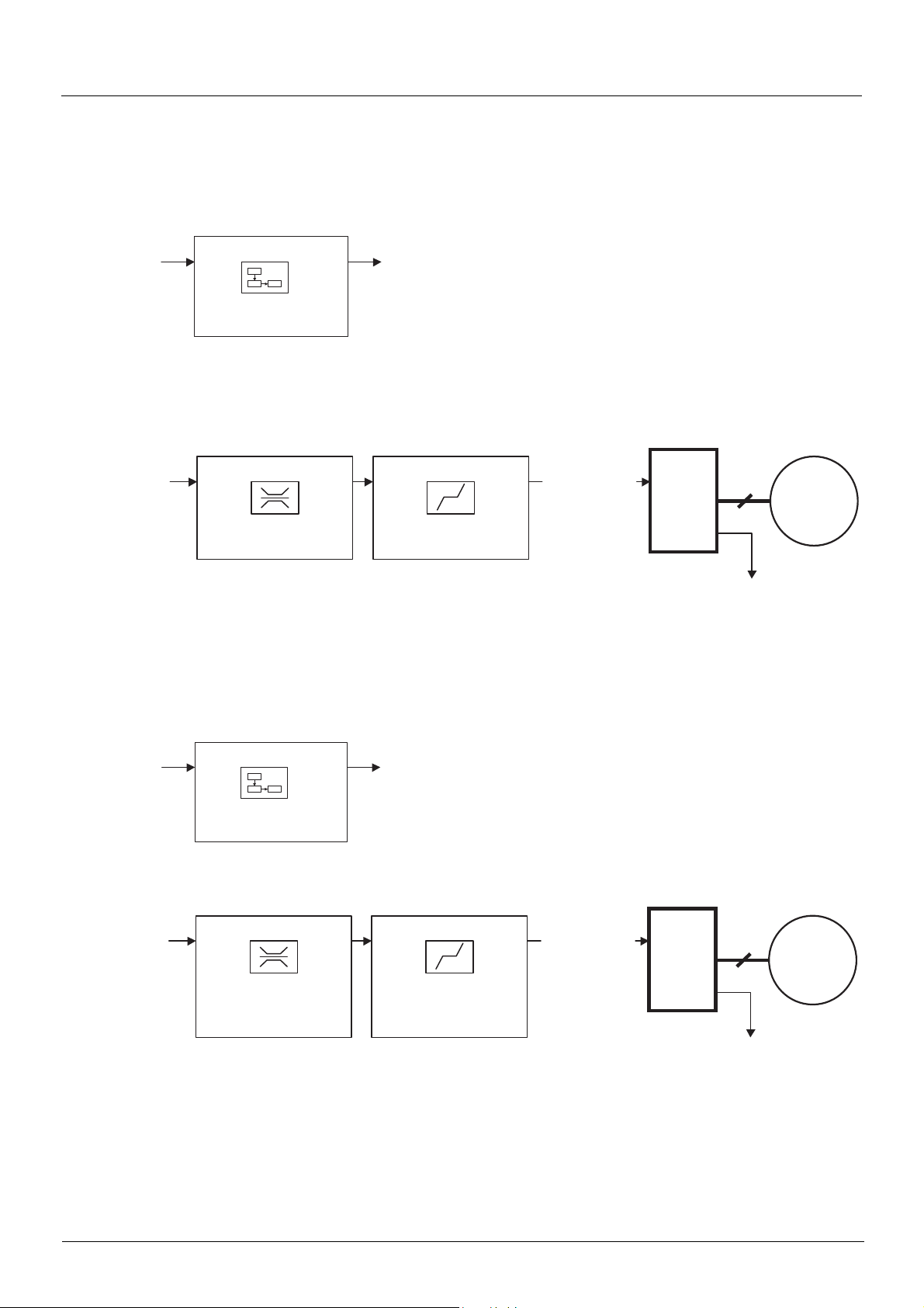
Functional description
b Drive operation involves two main functions, which are illustrated in the two diagrams below (the values in brackets are the CANopen
addresses of the parameters):
• Control diagram:
• Simplified diagram of speed control in "Velocity" mode:
b The main parameters are shown with their CiA402 name and their CiA402/Drivecom index (the values in brackets are the parameter
codes).
These diagrams translate as follows for the Altivar system:
• Control diagram:
• Simplified diagram of speed regulation in "Velocity" mode:
15 BBV19480 11/2011
CiA402 profile
Fault
Power section line supply present or absent
Power section line supply present
Transition condition
with example of command
Value of
status word
Power
absent
Power
present
Status display on
graphic display terminal
State
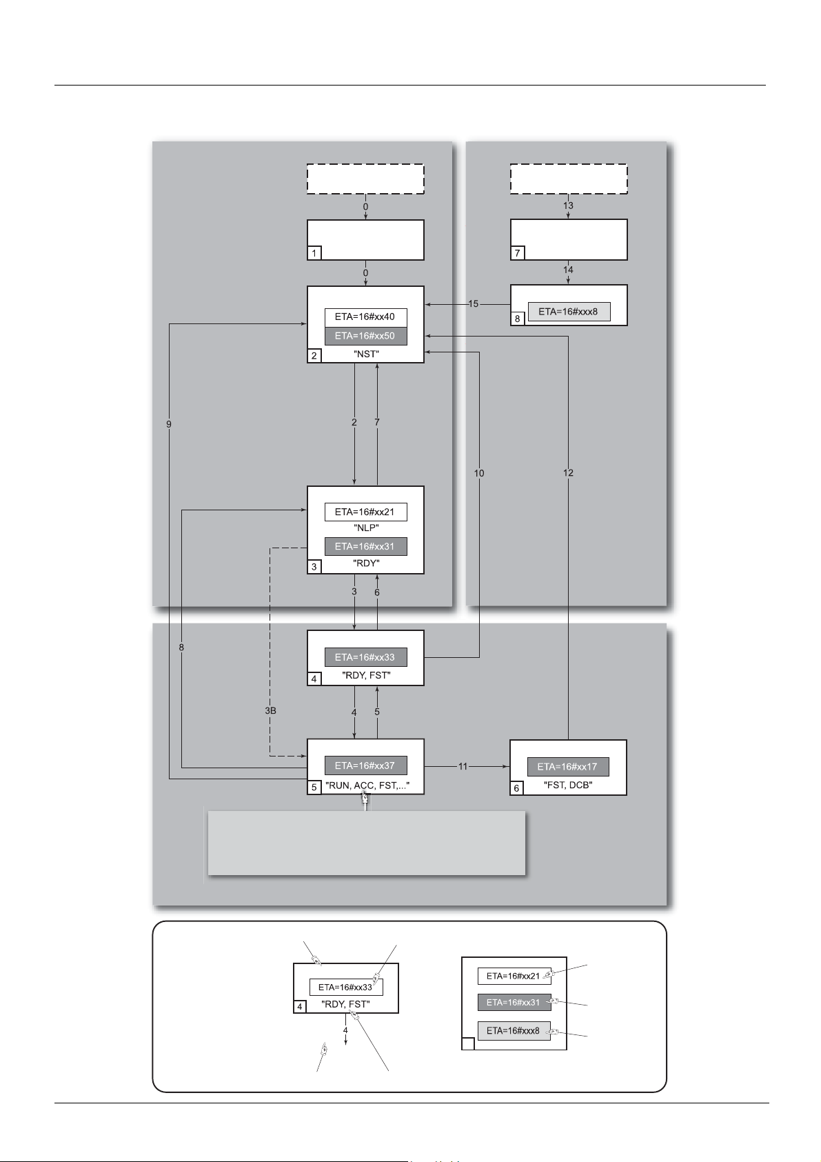
Key:
Examples:
ETA=16#0637: Stop or forward, speed reached
ETA=16#8637: Stop or reverse, speed reached
ETA=16#0237: For w ar d, acce le ra ti ng or dece le r ati n g
ETA=16#8237: Reverse, accelerating or decelerating
Enable
operation
CMD=16#xxxF
Switched on
Ready to switch on
or
Switched on
Operation enabled
Power absent
or present
Enable
operation
CMD=16#xxxF
Disable
operation (DOTD = 1)
CMD=16#0007
or
fast stop
Quick stop
CMD=16#0002
Quick stop active
Switch on
CMD=16#xxxF
Shutdown
CMD=16#0006
Switch on
CMD=16#0007
Shutdown
CMD=16#0006
Disable
voltage
CMD=16#0000
or
Quick stop
CMD=16#0002
or
STOP key
or
freewheel stop
at the terminals
or
modification
of a configuration
parameter
If Quick stop option code
= 2 ou 3:
transition after stop.
If Quick stop option code
= 6:
Disable voltage
CMD=16#0000
or
STOP key
or
freewheel stop at
terminals
Disable
voltage
CMD=16#0000
or
Quick stop
CMD=16#0002
or
STOP key
Shutdown
CMD=16#0006
Disable voltage
CMD=16#0000
or
STOP key
or
freewheel stop at
the terminals
or
Power Removal
or
Switch on disabled
Fault disappeared
and faults reset
CMD=16#0080
Not ready to switch on
Entry into
state chart
Fault reaction active
From all states
Fault
Fault
CiA402 state chart
BBV19480 11/2011 16

CiA402 profile
Description of states
Each state represents an internal reaction by the drive.
This chart will change depending on whether the control word is sent (CMD) or an event occurs (a fault, for example).
The drive state can be identified by the value of the status word (ETA).
1 - Not ready to switch on
Initialization starts. This is a transient state invisible to the communication network.
2 - Switch on disabled
The drive is inactive.
The drive is locked, no power is supplied to the motor.
For a separate control section, it is not necessary to supply AC power to the power section.
For a separate control section with line contactor, the contac tor is not controlled.
The configuration and adjustment parameters can be modified.
3 - Ready to switch on
Awaiting power section line supply.
For a separate control section, it is not ne cessa ry to s uppl y AC power to the p ower sec tion, b ut the sy ste m wil l expe ct it i n o rder to chan ge
to state "4
For a separate control section with line contactor, the contac tor is not controlled.
- Switched on".
The drive is locked, no power is supplied to the motor.
The configuration and adjustment parameters can be modified.
4 - Switched on
The drive is supplied with AC power but is stationary.
For a separate control section, the power section line supply must be present.
For a separate control section with line contactor, the contac tor is controlled.
The drive is locked, no power is supplied to the motor.
The power stage of the drive is ready to operate, but voltage has not yet been applied to the output.
The adjustment parameters can be modified.
Modification of a configuration parameter returns the drive to state "2 - Switch on disabled".
5 - Operation enabled
The drive is running.
For a separate control section, the power section line supply must be present.
For a separate control section with line contactor, the contac tor is controlled.
The drive is unlocked, power is supplied to the motor.
The drive functions are activated and voltage is applied to the motor terminals.
However, in the case of an open-loop drive, if the reference is zero or the "Halt" command i s applied, no power is suppli ed to the motor and
no torque is applied.
Auto-tuning (tUn) requires an injection of current into the motor. The drive must therefore be in state "5 - Operation enabled" for this
command.
The adjustment parameters can be modified.
The configuration parameters cannot be modified.
Note: The command "4 - Enable operation " must be taken into consideration only if the channel is valid (see Communication monitoring
page 48). In particular, if the channel is involved in the command and the reference, transition 4 will take place only after the
reference has been received for the first time.
Note: The drive must be in state "5 - Operation enabled in order to be able to do [Angle auto-test] (ASA).
The reaction of the drive to a "Disable operation" command depends on the value of the "Disable operation opti on code" (DOTD) parameter:
• If the "Disable operation option code" parameter has the value 0, the drive ch anges to "4 - Switche d on" and s tops i n free wheel st op.
• If the "Disable operation option code" parameter has the value 1, the drive stops on ramp and then changes to "4 - Switched on".
17 BBV19480 11/2011

CiA402 profile
6 - Quick stop active
Emergency stop
The drive performs a fast stop, after which restarting will only be possible once the drive has changed to the "Switch on disabled" state.
During fast stop, the drive is unlocked and power is supplied to the motor.
The configuration parameters cannot be modified.
The condition for transition 12 to state "2 - Switch on disabled" depends on the value of the parameter "Quick stop option code" (QSTD):
• If the "Quick stop option code" parameter has the value 2, the drive stops according t o the fast st op ramp and then chang es to s tate
"2 - Switch on disabled".
• If the "Quick stop option code" parameter has the value 3, the dri ve stops accordi ng to c urrent limit ing an d then change s to s tate "2 -
Switch on disabled".
• If the "Quick stop option code" parameter has the value 6, the drive stops according to the fast stop ramp and then remains in state
"6 - Quick stop active" until:
- A "Disable voltage" command is received
- Or the STOP key is pressed
- Or there is a freewheel stop command via the terminals
7 - Fault reaction active
Transient state during which the drive performs an action appropriate to the type of fault.
The drive function is activated or deactivated according t o the type of reaction configured in the fault management parameters.
8 - Fault
Drive faulty.
The drive is locked, no power is supplied to the motor.
Summary
State
1 - Not ready to switch on Not required No Yes
2 - Switch on disabled Not required No Yes
3 - Ready to switch on Not required No Yes
4 - Switched on Required No
5 - Operation enabled Required
6 - Quick stop active Required Yes, during fast stop No
7 - Fault reaction active
8 - Fault Not required No Yes
Power section line supply for
separate control section
Depends on fault management
configuration
Power supplied to motor
Yes, apart from an open-loop
drive with a zero reference or in
the event of a "Halt" command
for an open-loop drive.
Depends on fault management
configuration
Modification of configuration
Yes, return to "2 - Switch on
disabled" state
parameters
No
-
BBV19480 11/2011 18

CiA402 profile
Control word (CMD)
bit 7 bit 6 bit 5 bit 4 bit 3 bit 2 bit 1 bit 0
Fault reset
Enable operation
Quick stop Enable voltage
Switch on
Reserved (=0) Reserved (=0) Reserved (=0)
Ack. fault
Assignable Assignable Assignable Assignable
Command
Shutdown 2, 6, 8
Switch on 3 4 - Switched on x x 1 1 1 16#0007
operation
operation
Disable voltage 7, 9, 10, 12
Quick stop
Fault reset 15
bit 15 bit 14 bit 13 bit 12 bit 11 bit 10 bit 9 bit 8
bit 7 bit 3 bit 2 bit 1 bit 0
Fault
reset
x x 1 1 0 16#0006
x 1 1 1 1 16#000F
x x x 0 x 16#0000
x x 0 1 x 16#0002
0 V 1 x x x x 16#0080
Enable
Disable
Transition
address
4
5 4 - Swit c h ed on x 0 1 1 1 16#0007
11
7, 10
Final state
3 - Ready to
switch on
5 - Operation
enabled
2 - Switch on
disabled
6 - Quick stop
active
2 - Switch on
disabled
2 - Switch on
disabled
Run command
By default,
direction of
rotation
command.
Enable
operation
Quick
Emergency
stop
Reserved (=0) Reserved (=0)
Enable
stop
voltage
Authorization
to supply AC
power
Switch on
Example value
Contactor
control
Halt
Halt
x: Value is of no significance for this command.
0 V 1: Command on rising edge.
19 BBV19480 11/2011

CiA402 profile
Stop commands:
The "Halt" command enables movement to be int errupted wi t hout ha vin g t o leave t he "5 - Operat ion ena bl ed" stat e. The st op is performed
in accordance with the [Type of stop] (Stt) parameter.
In the case of an open-loop drive, if the "Halt" command is active, no power is supplied to the motor and no torque is applied.
In the case of a closed-loop drive, if the "Halt" command is active , power c ontinues t o be supplie d to the motor and t orque is appl ied during
stopping.
Regardless of the assignment of the [Type of stop] (Stt) parameter ([Fast stop] (FSt), [Ramp stop] (rMP), [Freewheel] (nSt), or [DC
injection] (dCI)), the drive remains in the "5 - Operation enabled" state.
WARNING
RISK OF EQUIPMENT DAMAGED
When logic braking is configured, it is necessary to use "Halt" command (bit 8 of CMD word) to stop.
Failure to follow this instruction can result in death or serious injury.
A Fast Stop command at the terminals or using a bit of the control word assigned to Fast Stop causes a change to the "4 - Switched on"
state. A "Halt" command does not cause this transition.
A Freewheel Stop command at the terminals or using a bit of the control word assigned to Freewheel Stop causes a change to the "2 Switch on disabled" state.
Assigning control word bits
In the CiA402 profile, fixed assignment of a function input is po ssible using the following codes:
Bit Integrated Modbus CANopen Network card "Controller Inside" card
bit 11 C111 C211 C311 C411
bit 12 C112 C212 C312 C412
bit 13 C113 C213 C313 C413
bit 14 C114 C214 C314 C414
bit 15 C115 C215 C315 C415
For example, to assign the DC injection braking to bit 13 of CANopen, simply configure the [DC injection assign.] (dCI) parameter with
the [C213] (C213) value.
Bit 11 is assigned by default to the operating direction command [Reverse assign.] (rrS).
BBV19480 11/2011 20

CiA402 profile
Status word (ETA)
bit 7 bit 6 bit 5 bit 4 bit 3 bit 2 bit 1 bit 0
Warning
Alarm
bit 15 bit 14 bit 13 bit 12 bit 11 bit 10 bit 9 bit 8
Direction of
rotation
Switch on
disabled
Power section
line supply
disabled
Stop via
STOP key
Quick stop
Emergency
stop
Reserved (=0) Reserved (=0)
Voltage
enabled
Power section
line supply
present
Fault
Fault
Internal limit
active
Reference
outside limits
Operation
enabled
Running Ready
Target
reached
Reference
reached
Switched on
Remote
Command or
reference via
network
Ready to
switch on
Awaiting
power section
line supply
Reserved (=0)
bit 6 bit 5 bit 4 bit 3 bit 2 bit 1 bit 0
Status
1 -Not ready to
switch on
2 -Switch on
disabled
3 -Ready to
switch on
4 -Switched on 0 1 1 0 0 1 1 16#0023
5 -Operation
enabled
6 -Quick stop
active
7 - Fault reaction
active
8 -Fault 0 x x 1 0 0 0
x: In this state, the value of the bit can be 0 or 1.
(1)
This mask can be used by the PLC program to test the chart state.
Switch on
disabled
0 x x 0 0 0 0 -
1 x x 0 0 0 0 16#0040
0 1 x 0 0 0 1 16#0021
0 1 1 0 1 1 1 16#0027
0 0 1 0 1 1 1 16#0007
0 x x 1 1 1 1 -
Quick
stop
Voltage
enabled
Fault
Operation
enabled
Switched onReady to
switch on
ETA
masked by
16#006F
16#0008
or 16#0028
(1)
(2)
(2)
Fault following state "6 - Quick stop active".
21 BBV19480 11/2011
CiA402 profile
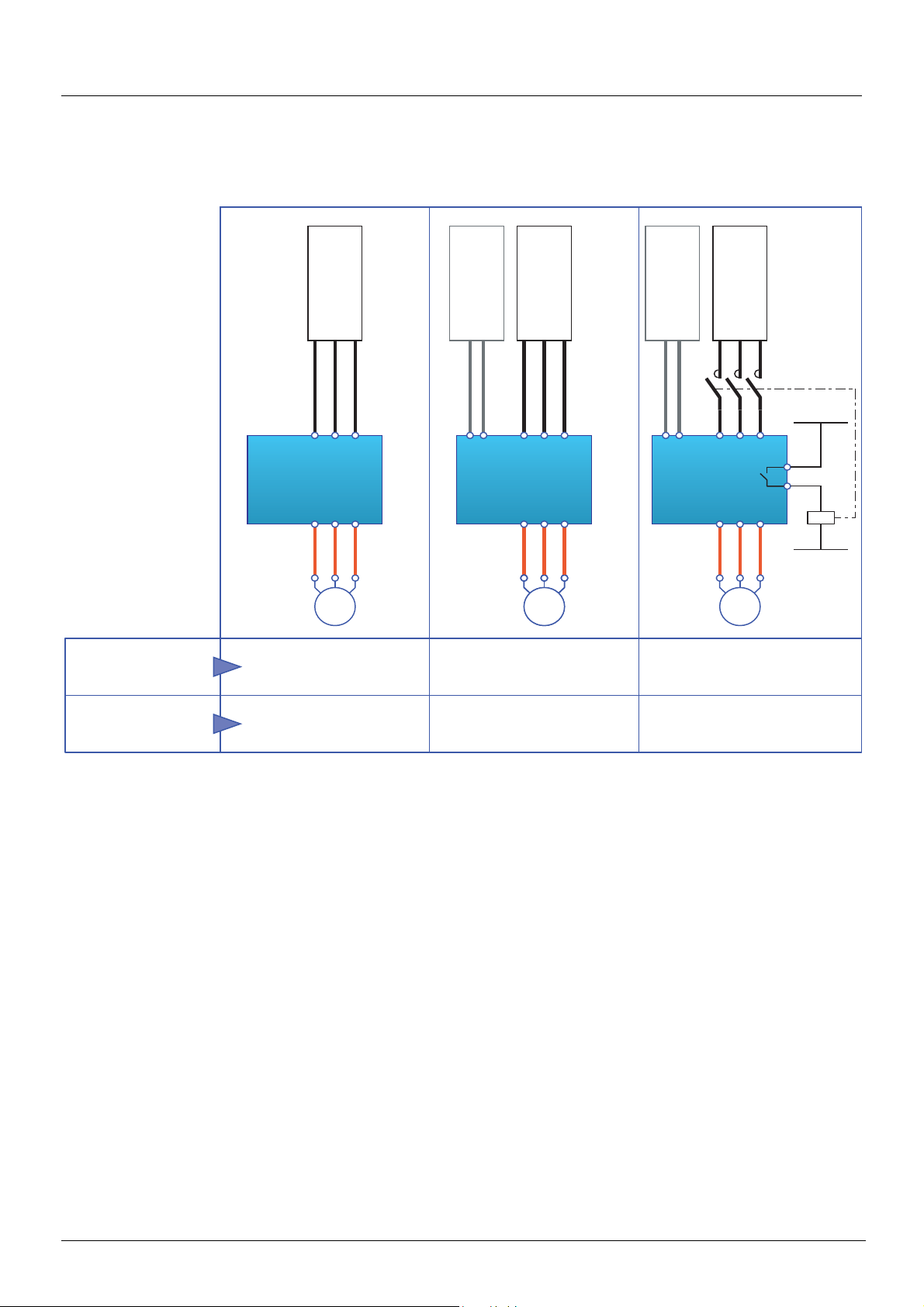
M MM M
Power section
line supply
Power section
line supply
Control section
power supply
Direct
Not separate
(1)
Direct
Separate
Line contactor
controlled by the drive
Separate
DRIVE DRIVE DRIVE
Power section
line supply
Power section
line supply
Control section
power supply
Control section
power supply
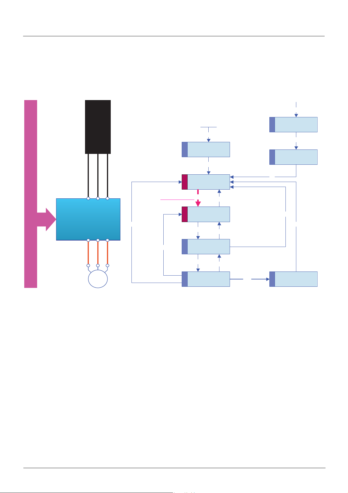
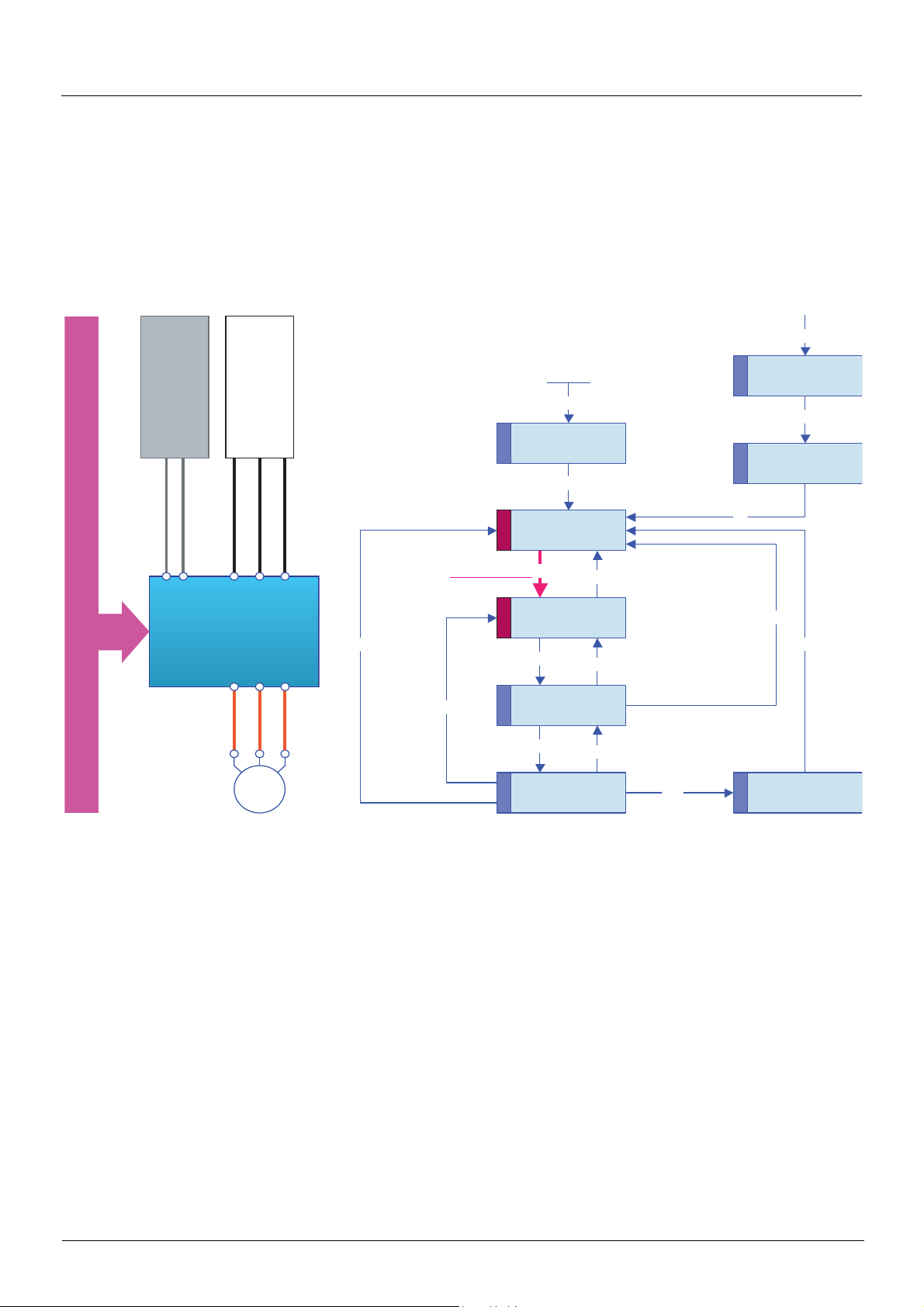
Starting sequence
The command sequence in the state chart depends on how power is being supplied to the drive.
There are three possible s cen a r io s :
(1)
The power section supplies the control section.
BBV19480 11/2011 22
CiA402 profile
M
2
3
4
5
6
7
1
11
9
8
12
10
15
14
13
0
1
2
3
4
5 6
8
7
Power section
line supply
Bus or network
DRIVE
Not ready to
switch on
Entry into state chart
Switch on
disabled
Ready to
switch on
Switched on
Operation
enabled
Quick stop
active
Fault
Fault reaction
active
From all states
Shutdown
Disable voltage
or Quick stop
Shutdown
Disable
operation
Disable
voltage
Enable
operation
Shutdown
Switch on
Disable voltage
or Quick stop
Quick stop
Sequence for a drive powered by the power section line supply
Both the power and control sections are powered by the power section line supply.
If power is supplied to the control section, it has to be supplied to the power section as well.
The following sequence must be applied:
b Step 1
• Send the "2 - Shutdown" command
23 BBV19480 11/2011

CiA402 profile
M
2
3
5
6
7
1
11
9
8
12
10
15
14
13
0
1
2
3
4
5
6
8
7
4
Not ready to
switch on
Entry into state chart
Switch on
disabled
Ready to
switch on
Switched on
Operation
enabled
Quick stop
active
Fault
Fault reaction
active
From all states
Switch on
Disable voltage
or Quick stop
Shutdown
Disable
operation
Disable
voltage
Enable
operation
Shutdown
Switch on
Disable voltage
or Quick stop
Quick stop
Power section
line supply
Bus or network
DRIVE
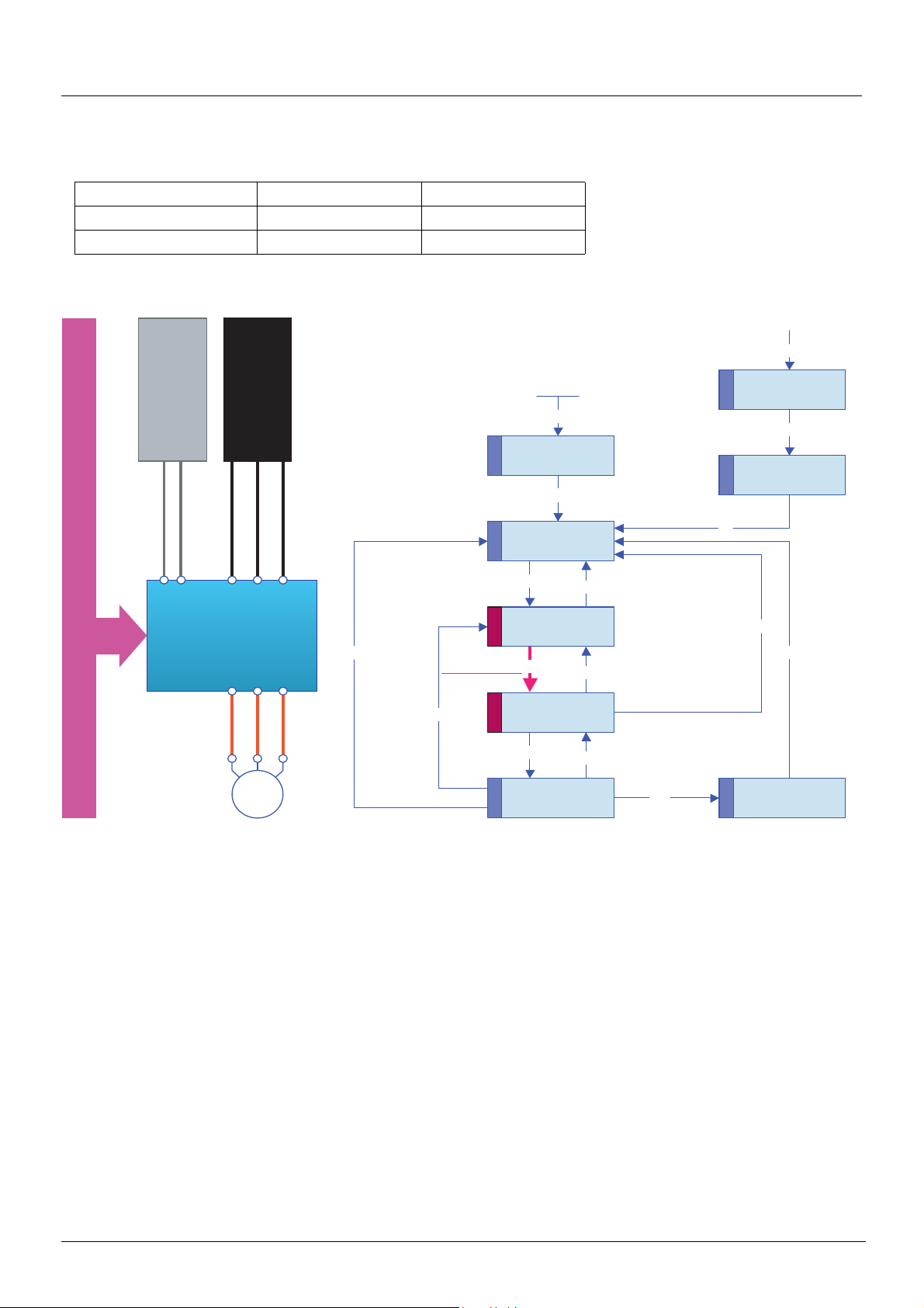
b Step 2
• Check that the drive is in the "3 - Ready to switch on" state.
• Then send the "4 - Enable operation" command.
• The motor can be controlled (send a reference not equal to zero).
Note: It is possible, but not necessary, to send the "3 - Switch on" command followed by the "4 - Enable Operation" command to switch
successively into the states "3
The "4 - Enable operation" command is sufficient.
BBV19480 11/2011 24
- Ready to Switch on", "4 - Switched on" and then "5 - Operation Enabled".
CiA402 profile
M
2
3
4
5
6
7
1
11
9
8
12
10
15
14
13
0
1
2
3
4
5 6
8
7
Power section
line supply
Bus or network
DRIVE
Control section
power supply
Not ready to
switch on
Entry into state chart
Switch on
disabled
Ready to
switch on
Switched on
Operation
enabled
Quick stop
active
Fault
Fault reaction
active
Shutdown
Disable voltage
or Quick stop
Shutdown
Disable
operation
Disable
voltage
Enable
operation
Shutdown
Switch on
Disable voltage
or Quick stop
Quick stop
From all states
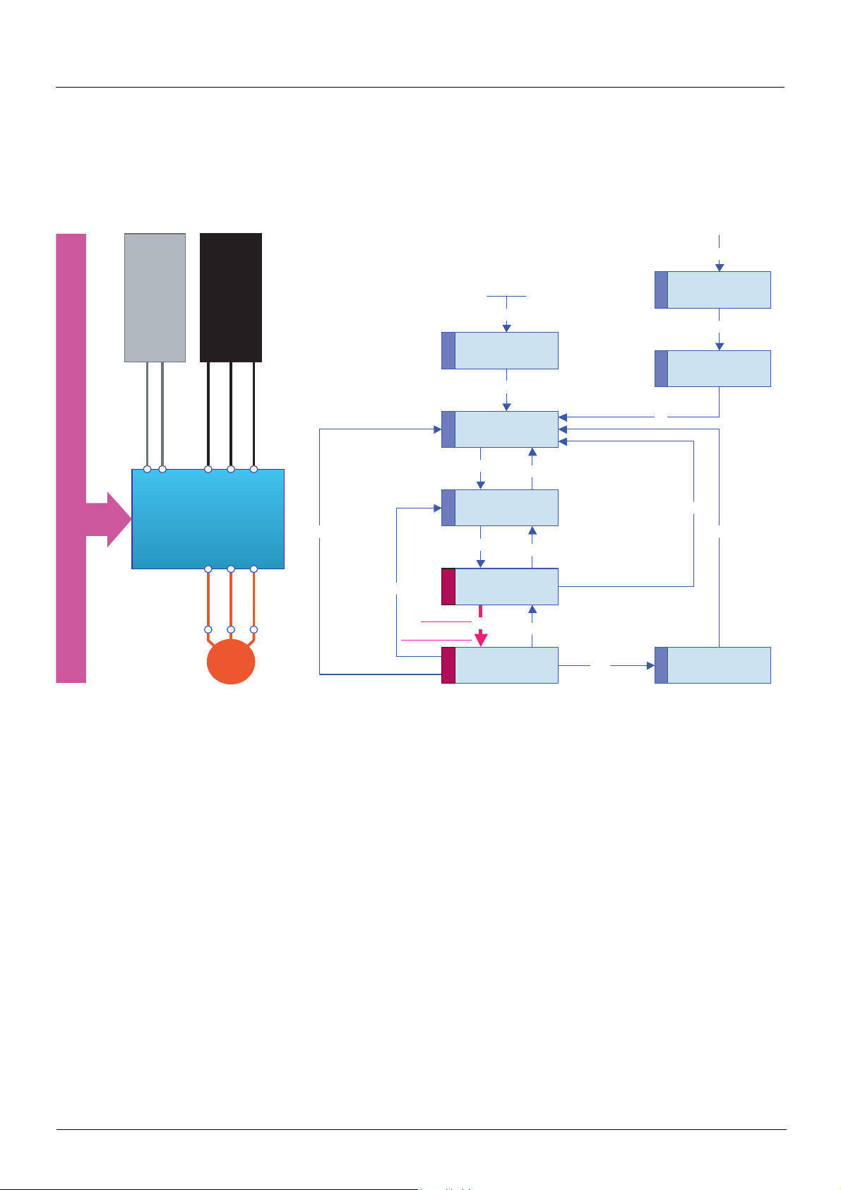
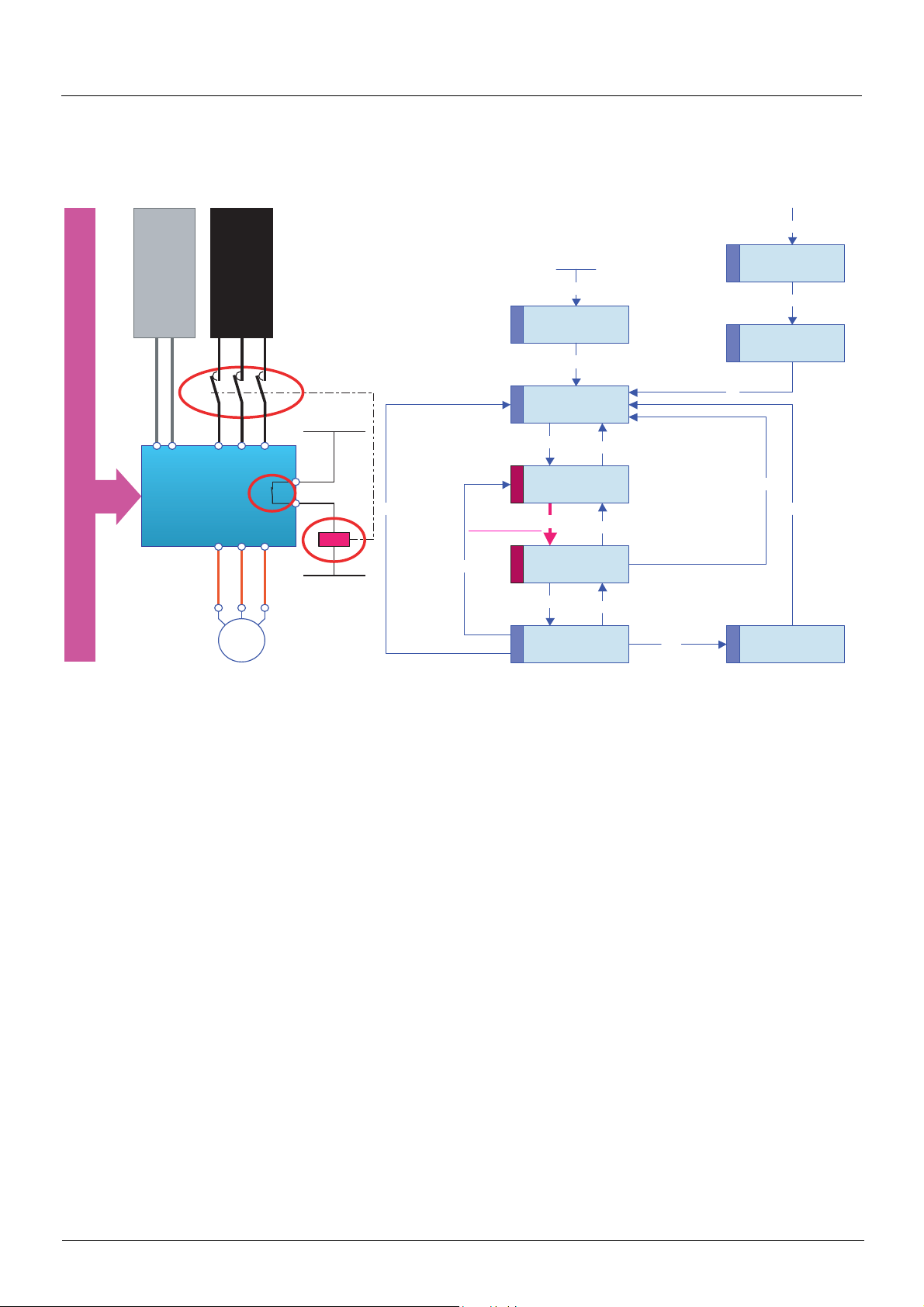
Sequence for a drive with separate control section
Power is supplied separately to the power and control sections.
If power is supplied to the control section, it does not have to be supplied to the power section as well.
The following sequence must be applied:
b Step 1
• The power section line supply is not necessarily present.
• Send the "2 - Shutdown" command
25 BBV19480 11/2011
CiA402 profile
M
2
3
4
5
6
7
1
11
9
8
12
10
15
14
13
0
1
2
3
4
5 6
8
7
Power section
line supply
Bus or network
DRIVE
Control section
power supply
Not ready to
switch on
Entry into state chart
Switch on
disabled
Ready to
switch on
Switched on
Operation
enabled
Quick stop
active
Fault
Fault reaction
active
From all states
Shutdown Disable voltage
or Quick stop
Shutdown
Disable
operation
Disable
voltage
Enable
operation
Shutdown
Switch on
Disable voltage
or Quick stop
Quick stop
b Step 2
• Check that the drive is in the "3 - Ready to switch on" state.
• Check that the power section line supply is present ("Voltage enabled" of the status word).
Power section line supply Terminal display Status word
Absent nLP 16#pp21
Present rdY 16#pp31
• Send the "3 - Switch on" command
BBV19480 11/2011 26
CiA402 profile
M
2
3
4
5
6
7
1
11
9
8
12
10
15
14
13
0
1
2
3
4
5 6
8
7
Power section
line supply
Bus or network
DRIVE
Control section
power supply
Not ready to
switch on
Entry into state chart
Switch on
disabled
Ready to
switch on
Switched on
Operation
enabled
Quick stop
active
Fault
Fault reaction
active
From all states
Shutdown Disable voltage
or Quick stop
Shutdown
Disable
operation
Disable
voltage
Enable
operation
Shutdown
Switch on
Disable voltage
or Quick stop
Quick stop
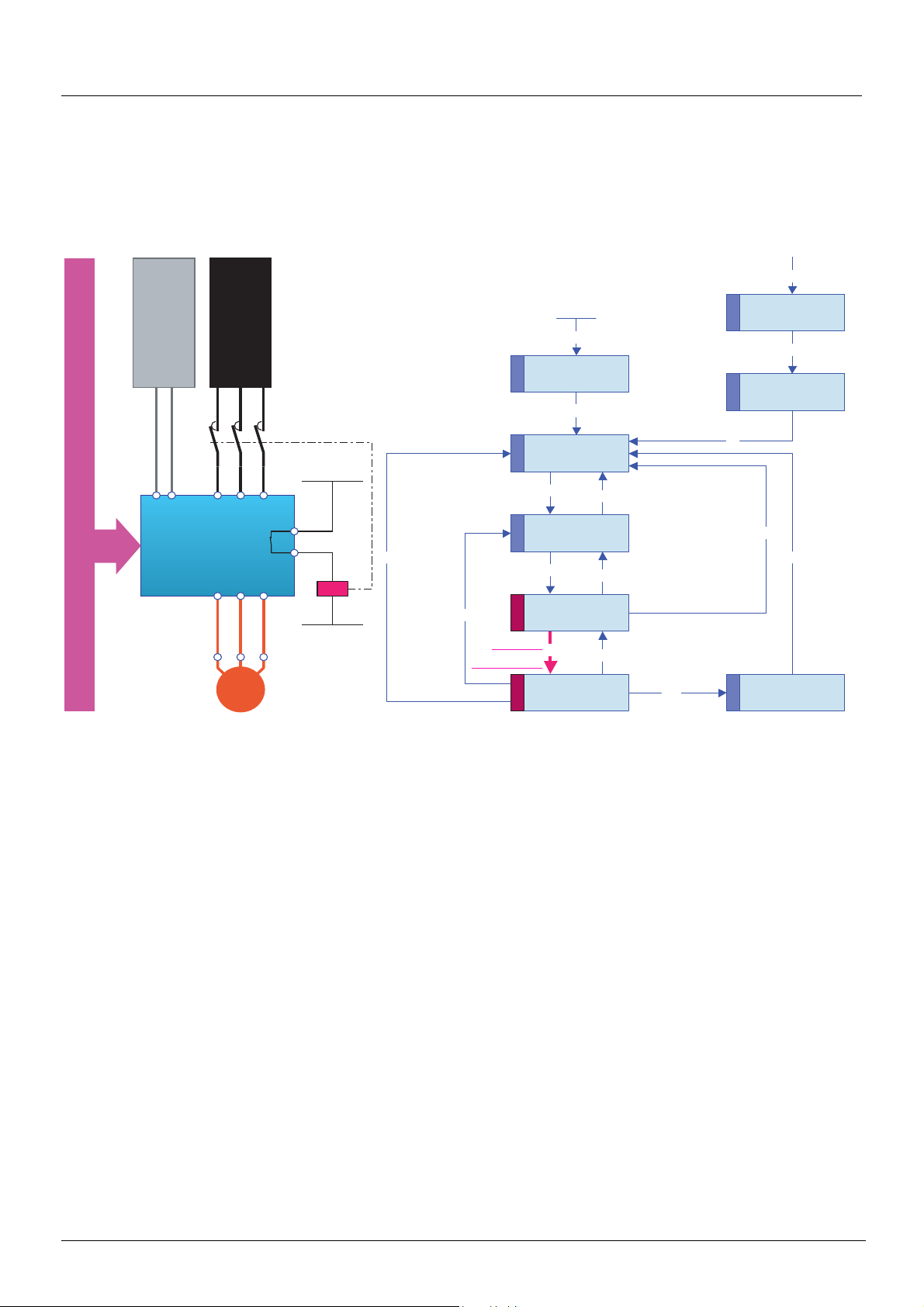
b Step 3
• Check that the drive is in the "4 - Switched on" state.
• Then send the "4 - Enable operation" command.
• The motor can be controlled (send a reference not equal to zero).
• If the power section line supply is still not pre sent in the "4 - Switched on" state after a t ime delay [Mains V. time out] (LCt), the drive
will switch to fault mode (LCF).
27 BBV19480 11/2011
CiA402 profile
M
2
3
4
5
6
7
1
11
9
8
12
10
15
14
13
0
1
2
3
4
5 6
8
7
Power section
line supply
Bus or network
DRIVE
Control section
power supply
Not ready to
switch on
Entry into state chart
Switch on
disabled
Ready to
switch on
Switched on
Operation
enabled
Quick stop
active
Fault
Fault reaction
active
Shutdown
Disable voltage
or Quick stop
Shutdown
Disable
operation
Disable
voltage
Enable
operation
Shutdown
Switch on
Disable voltage
or Quick stop
Quick stop
From all states
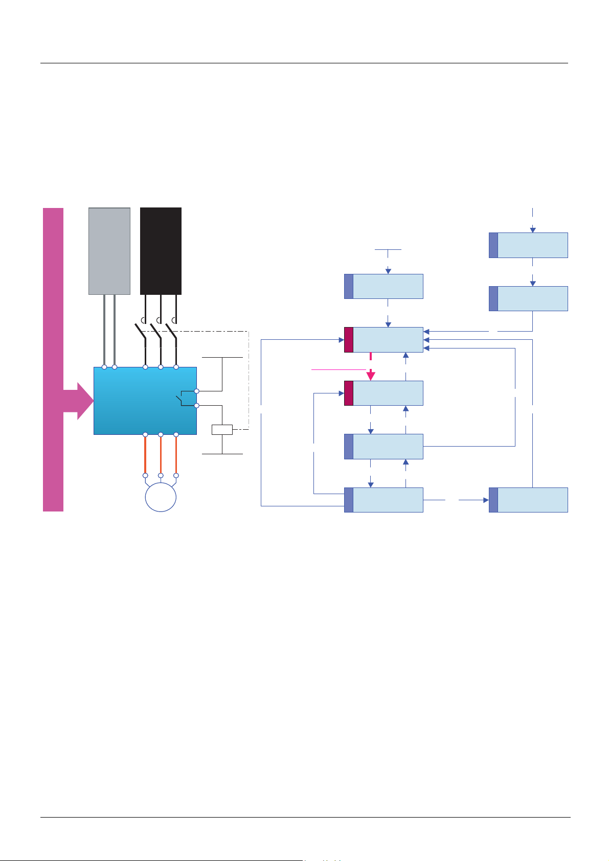
Sequence for a drive with line contactor control
Power is supplied separately to the power and control sections.
If power is supplied to the control section, it does not have to be supplied to the power secti on as well. The drive controls the line contactor.
The following sequence must be applied:
b Step 1
• The power section line supply is not present as the line contactor is not being controlled.
• Send the "2 - Shutdown" command
BBV19480 11/2011 28
CiA402 profile
M
2
3
4
5
6
7
1
11
9
8
12
10
15
14
13
0
1
2
3
4
5 6
8
7
Power section
line supply
Bus or network
DRIVE
Control section
power supply
Not ready to
switch on
Entry into state chart
Switch on
disabled
Ready to
switch on
Switched on
Operation
enabled
Quick stop
active
Fault
Fault reaction
active
From all states
Shutdown
Disable voltage
or Quick stop
Shutdown
Disable
operation
Disable
voltage
Enable
operation
Shutdown
Switch on
Disable voltage
or Quick stop
Quick stop
b Step 2
• Check that the drive is in the "3 - Ready to switch on" state.
• Send the "3 - Switch on" command, which will close the line contactor and switch on the power section line supply.
29 BBV19480 11/2011
CiA402 profile
M
2
3
4
5
6
7
1
11
9
8
12
10
15
14
13
0
1
2
3
4
5 6
8
7
Power section
ine supply
Bus or network
DRIVE
Control section
power supply
Not ready to
switch on
Entry into state chart
Switch on
disabled
Ready to
switch on
Switched on
Operation
enabled
Quick stop
active
Fault
Fault reaction
active
From all states
Shutdown
Disable voltage
or Quick stop
Shutdown
Disable
operation
Disable
voltage
Enable
operation
Shutdown
Switch on
Disable voltage
or Quick stop
Quick stop
b Step 3
• Check that the drive is in the "4 - Switched on" state.
• Then send the "4 - Enable operation" command.
• The motor can be controlled (send a reference not equal to zero).
• If the power section line supply is still not pre sent in the "4 - Switched on" state after a t ime delay [Mains V. time out] (LCt), the drive
will switch to fault mode (LCF).
BBV19480 11/2011 30
 Loading...