

Schneider Electric atv71lift Programming manual [EN]
2354235 11/2008
Altivar LIFT
Variable speed drive
for synchronous and asynchronous lift motors
Programming Manual
(Software V5.4)
11/2011
BBV19478
www.schneider-electric.com


Table of contents
Before you begin _____________________________________________________________________________________________ 4
Documentation structure _______________________________________________________________________________________ 5
Software enhancements _______________________________________________________________________________________ 6
Presentation_________________________________________________________________________________________________ 7
Standard EN81-1 certification ___________________________________________________________________________________ 8
Vocabulary__________________________________________________________________________________________________ 9
Setup procedure_____________________________________________________________________________________________ 10
Factory configuration _________________________________________________________________________________________ 11
Setup - Preliminary recommendations ____________________________________________________________________________ 12
Graphic terminal_____________________________________________________________________________________________ 14
Description of the terminal_______________________________________________________________________________ 14
Description of the graphic screen__________________________________________________________________________ 15
First power-up - [5. LANGUAGE] menu_____________________________________________________________________ 18
Subsequent power ups _________________________________________________________________________________ 19
Programming: Example of accessing a parameter ____________________________________________________________ 20
Quick navigation_______________________________________________________________________________________ 21
Integrated display terminal_____________________________________________________________________________________ 24
Functions of the display and the keys ______________________________________________________________________ 24
Accessing menus _____________________________________________________________________________________ 25
Accessing menu parameters _____________________________________________________________________________ 26
[2. ACCESS LEVEL] (LAC-)____________________________________________________________________________________ 27
Structure of the parameter tables________________________________________________________________________________ 30
Interdependence of parameter values____________________________________________________________________________ 31
Finding a parameter in this document ____________________________________________________________________________ 32
[1.1 LIFT] (LIF-) _____________________________________________________________________________________________ 33
[International unit] (SIU)________________________________________________________________________________ 119
[1.2 MONITORING] (SUP-) ___________________________________________________________________________________ 124
[1.3 SETTINGS] (SEt-)____________________________________________________________________________________ ___ 133
[1.4 MOTOR CONTROL] (drC-)________________________________________________________________________________ 145
[1.5 INPUTS / OUTPUTS CFG] (I-O-) ___________________________________________________________________________ 173
[1.6 COMMAND] (CtL-) ______________________________________________________________________________________ 203
[1.7 APPLICATION FUNCT.] (FUn-) ____________________________________________________________________________ 216
[1.8 FAULT MANAGEMENT] (FLt-)_____________________________________________________________________________ 269
[1.9 COMMUNICATION] (COM-)_______________________________________________________________________________ 291
[1.10 DIAGNOSTICS] _______________________________________________________________________________________ 295
[1.11 IDENTIFICATION]______________________________________________________________________________________ 298
[1.12 FACTORY SETTINGS] (FCS-)____________________________________________________________________________ 299
[1.13 USER MENU] (USr-)____________________________________________________________________________________ 302
[1.14 CONTROL. INSIDE CARD] (PLC-)_________________________________________________________________________ 303
[3 OPEN/SAVE AS] _________________________________________________________________________________________ 304
[4. PASSWORD] (COd-) _____________________________________________________________________________________ 306
[6 MONITORING CONFIG.]___________________________________________________________________________________ 308
[7 DISPLAY CONFIG.]_______________________________________________________________________________________ 312
[MULTIPOINT SCREEN] _____________________________________________________________________________________ 317
Maintenance_______________________________________________________________________________________________ 318
Diagnostics and Troubleshooting_______________________________________________________________________________ 319
User settings tables _________________________________________________________________________________________ 325
Index of functions___________________________________________________________________________________________ 327
Index of parameter codes ____________________________________________________________________________________ 328
BBV19478 11/2011 3
Before you begin
Read and understand these instructions bef ore performing any procedure using this drive.
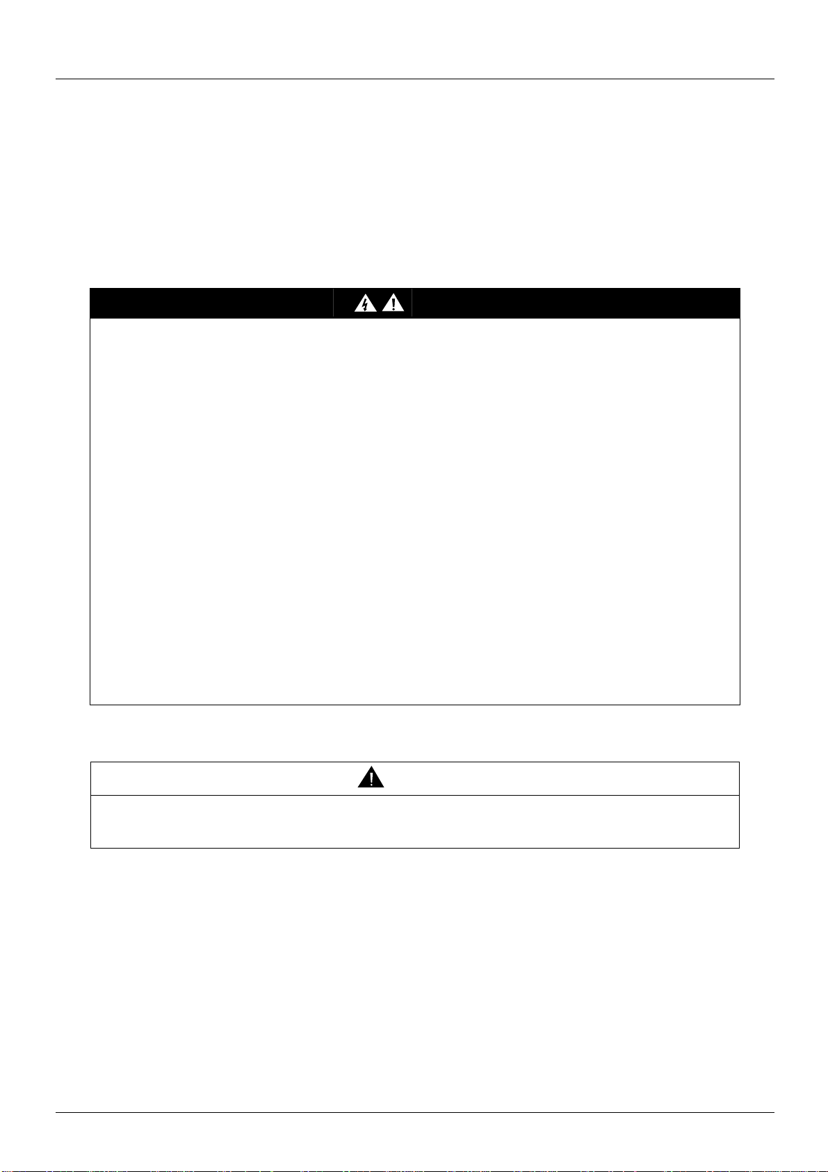
DANGER
HAZARDOUS ELECTRIC SHOCK, EXPLOSION OR ARC FLASH
• Read and understand the Installation Manual before inst alling or operating the ATV LIFT drive. Installation,
adjustment, repair, and maintenance must be performed by qualified personnel.
• The user is responsible for compliance with all international and national electrical standards in force concerning
protective grounding of all equipment.
• Many parts in this variable speed drive, including printed wiring boards, operate at line voltage. DO NOT TOUCH.
Use only electrically insulated tools.
• DO NOT touch unshielded components or terminal strip screw connections with volta ge present.
• DO NOT short across terminals PA/+ and PC/- or across the DC bus capacitors.
• Install and close all the covers before applying power or starting and stopping the drive.
• Before servicing the variable speed drive
- Disconnect all power.
- Place a “DO NOT TURN ON” label on the variable speed drive disconnect.
- Lock the disconnect in the open position.
• Disconnect all power including external control power that may be present before servicing the drive. WAIT
15 MINUTES to allow the DC bus capacitors to discharge. Then follow the DC bus voltage measuremen t procedure
given in the Installation Manual to verify that the DC voltage is less than 42 Vdc. The drive LEDs are not accurate
indicators of the absence of DC bus voltage.
Failure to follow these instructions will result in death or serious injury.
CAUTION
DAMAGED EQUIPMENT
Do not operate or install any drive that appears damaged.
Failure to follow this instruction can result in injury and/or equipment damage.
4 BBV19478 11/2011

Documentation structure
The following Altivar LIFT technical doc uments are available on www.schneider-electric.com
Installation manual
This describes how to assemble and connect the drive.
Programming Manual
This describes the functions, parameters and use of the drive terminal (integrated display terminal and graphic display terminal).
The communication functions are not described in this manual, but in the manual for the bus or network used.
Communication parameters manual
This manual describes:
• The drive parameters with specific information for use via a bus or communication network.
• The operating modes specific to communication (state chart).
• The interaction between communication and local control.
Manuals for Modbus®, CANopen®, Ethernet™, Profibus®, INTERBUS, Uni-Telway
®
and Modbus
Plus, etc.
These manuals describe the assembly, connection to the bus or network, signaling, diagnostics, and configuration of the communicationspecific parameters via the integrated display terminal or the graphic display terminal.
They also describe the communication services of the protocols.
BBV19478 11/2011 5

Software enhancements
Since the Altivar LIFT was first launched, it has benefited from the addition of several new functions. The software version has been
updated to V5.4.
Although this documentation relates to version V5.4, it can still be used with earlier versions.
Enhancements made to version V5.4 in comparison to V5.3
New parameters and functions
Menu [1.1 LIFT] (LIF-)
• New parameter [Preset speed selec] (PSEn) (see page 42)
• New parameter [Stop type ISP] (SttL) (see page 97
• New parameter [Delay Thermal fault] (dth) (see page 106
• New parameter [International unit] (SIU) page 119
• New parameters for the rescue mode : (see page 101)
- [Opt. rescue mode] (OrM): Optimized rescue mode.
- [Acc. time rescue] (rACC): Acceleration time during rescue.
- [Resc max cur r e nt ] (rCLI): Current limitation during rescue.
- [Calc. rescue power] (PMC): This is the power needed by the drive only during evacuation.
- [Cust. rescue speed] (OrSP): Maximum optimized rescue speed,
• New methods of assigning logic output (see page 43
- [Rescue dir.] (Opt): Optimized direction for rescue mode.
- [Rdy to run] (rdYr): The drive is ready to start or already started.
• New methods of assigning [Encoder usage] (EnU)
- [Slip Comp.] (COr):The encoder provides speed feedback for speed correction and monitoring. (s ee page 46
• New methods of assigning [Thermal alarm stop] (SAt) (see page 106
- [No] (nO): Function inactive
- [Th. mot drv] (tH): Defered stop on drive thermal alarm or motor thermal alarm
- [PTC] (PtC): Defered stop on PTC alarm
- [ALL] (ALL): Defered stop on drive thermal alarm, motor thermal alarm or PTC alarm
• New factory setting for [Dis. operat opt code] (dOtd) (see page 137
- [Freewheel] (nSt) to [Ramp stop] (rMp)
)
)
[OUTPUTS] (OUt-))
)
)
)
Menu [1.7 APPLICATION FUNCT.] (FUn-)
• New parameter [Stop type ISP] (SttL). (see page 264)
• New parameters for the rescue mode: (see page 265
- [Opt. rescue mode] (OrM): Optimized rescue mode.
- [Acc. time rescue] (rACC): Acceleration time during rescue.
- [Resc max cur r e nt ] (rCLI): Current limitation during rescue.
- [Calc. rescue power] (PMC): This is the power needed by the drive only during evacuation.
- [Cust. rescue speed] (OrSP): Maximum optimized rescue speed,
• New parameter [Delay Thermal fault] (dth) (see page 278
)
)
6 BBV19478 11/2011
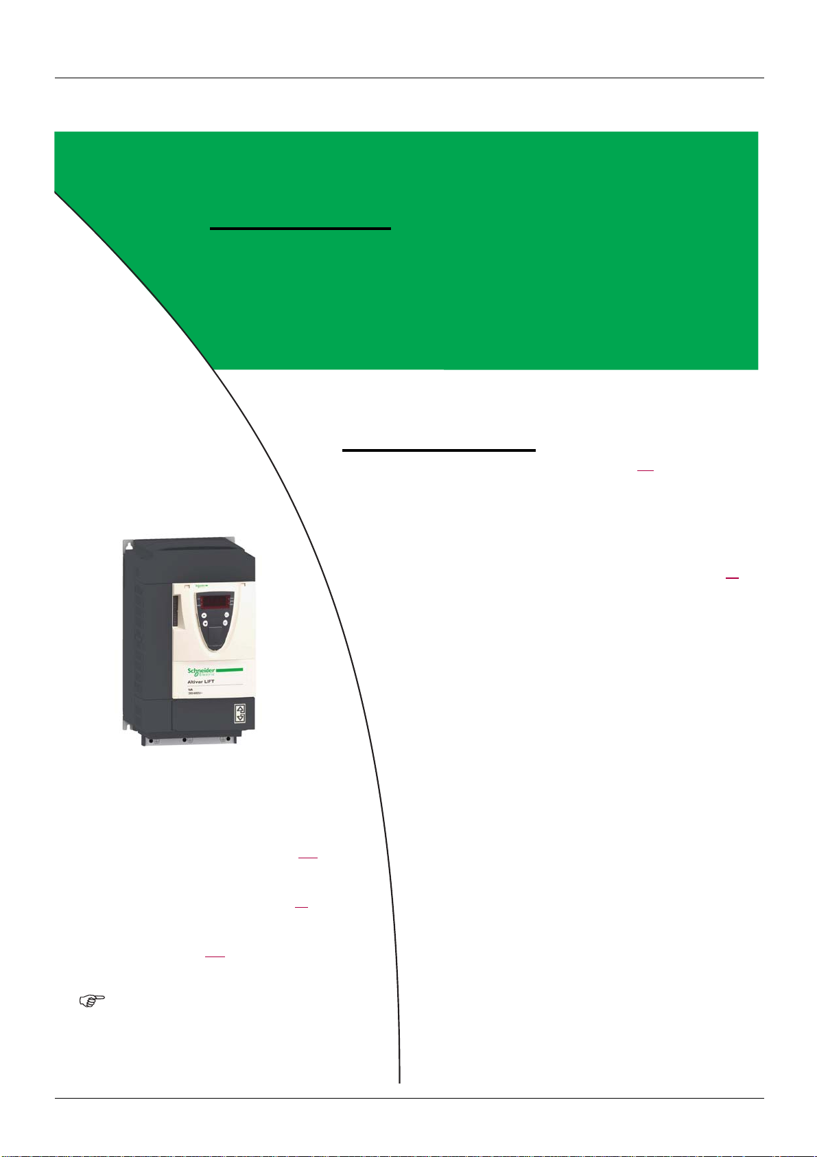
Presentation
WARNING
LOSS OF CONTROL
The speed loop implemented in the ATV LIFT is specifically adapted to lift applications.
It must only be used in a lift application.
Failure to follow these instructions can result in injury and/or equipment damage.
ATV LIFT has been specially developed for lift applications and therefore meets the requirements of lift installers:
• Quick, simple drive setup via a dedicated LIFT menu.
• Drive performance that offers optimum comfort.
• Integrated LIFT functions: special lift ra mp, i nspect ion fun cti on, rol lba ck mana gemen t, optimi zat i on of "h alf f loors ", UPS eva cuation,
etc.
ATV LIFT can only be used with lifts.
The following options are compatibles with ATV LIFT from a minimum version:
- graphic display terminal from the version V1.1IE24,
- universal encoder interface card (VW3A3409) from the version V1.2IE01.
ATV LIFT selection has been simplified: the sizing of the ATV LIFT is done with the nominal current
of the motor. This new policy adapts ATV LIFT references with synchronous motors. Maximum transient current has changed.
It was 1.5 In with ATV71L and is now 1.36 In with ATV LIFT.
When migrating a lift application from ATV71L to ATV LIFT, you have to check that the drive does not
reach [current Limitation] (CLI) state during acceleration or deceleration.
In case of current limitation, adapt the drive parameters if necessary:
- Increase [Acceleration time] (ACt)
- Decrease [Lift Leveling time] (LLt)
To improve the comfort in the lift, you have also the possibility to use the notch filter function.
• The previous ATV71L references not listed are no longer available. You have to take the higher power rating drive for substitution.
• Commercial reference construction: ATV71LDxxyyZ where:
- xx : Maximum continuous current at 380 Vac for N4 products and 230 Vac for M3 products.
- yy : Three phase supply voltage M3 = 230V & N4 = 380V.
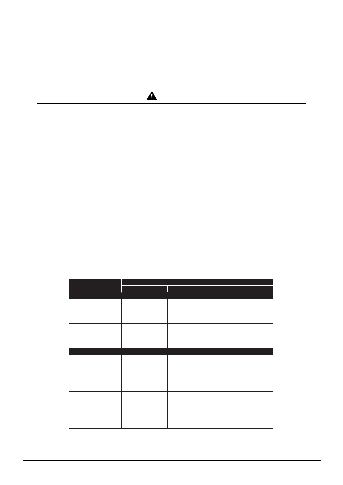
Current
Rating
27A 5,5kW
ATV71LU55M3Z ATV71LD27M3Z
Power
Rating
3-phase supply voltage : 200...240V
33A 7,5kW ATV71LU75M3Z ATV71LD33M3Z
54A 11kW ATV71LD11M3XZ ATV71LD54M3Z
66A 15kW
ATV71LD15M3XZ ATV71LD66M3Z
Catalog part number Mechanical Size
ATV71L
ATV LIFT
ATV71L
175*295*161 230*400*187
210*295*187 230*400*187
230*400*187 240*420*210
230*400*187 240*420*210
ATV LIFT
3-phase supply voltage : 380...480V
10A 4kW ATV71LU40N4Z ATV71LD10N4Z
155*260*161 175*295*161
14A 5,5kW ATV71LU55N4Z ATV71LD14N4Z
17A 7,5kW ATV71LU75N4Z ATV71LD17N4Z
27A 11kW ATV71LD11N4Z ATV71LD27N4Z
33A 15kW ATV71LD15N4Z ATV71LD33N4Z
48A 22kW ATV71LD22N4Z ATV71LD48N4Z
175*295*161 175*295*161
175*295*161 210*295*187
210*295*187 230*400*187
230*400*187 230*400*187
240*420*210 240*550*230
Note: the transfer from the graphic display terminal to the drive is possible from ATV71L to ATV LIFT.
The transfer from ATV LIFT to ATV71 L is not possible.
See [3 OPEN/SAVE AS] page 304
BBV19478 11/2011 7
for a complete description of configuration transfer.
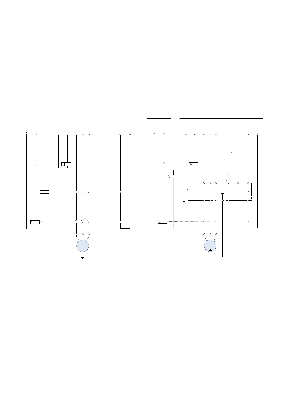
Standard EN81-1 certification
Safety Chain
Circuit
Contr ol devi ce
Command
LIFT COMMAND CONTROL CARD
Moni tori ng device
Feedbac k
K01
K01
K1
K2
K1
K2
K1
K2
UV W
UV W
M
3 ~
M
3 ~
Contr ol devi ce
Command
Safety Chain
Circuit
LIFT COMMAND CONTROL CARD
Moni tori ng device
Feedbac k
K01
K01
K1
K1
K2K2
K2
R1C
R1B
L1 L2 L3 PWR +24
R1 = RDY
ATV LIFT
U1
V1
W1
RdY or rdYr
EUROPEAN STANDARD EN 81-1 (Ref. No. EN 81-1:1998 E)
The ATV LIFT drive is now compliant with European Standard EN81-1 12.7.3 b) 2) and 3)
12 Lift machine
12.7 Stopping the machine and checking its stopped condition
12.7.3 A.C. or D.C. motor supplied and controlled by static elements
b) a system consisting of :
1) a contactor interrupting the current at all poles.
The coil of the contactor shall be released at least befo re each change in direc tion. If the cont actor does not release, any f urther movement
of the lift shall be prevented, and
2) a control device blocking the flow of energy in the static elements, and
3) a monitoring device to verify the blocking of the flow of energy each time the lift is stationary.
If, during a normal stopping period, the blocking of the flow of energy by the static elements is not effective, the monitoring device shall
cause the contactor to release and any further movement of the lift shall be prevented.
The ATV LIFT is in place of the power contactor K1.
- The contactor interrupting the current at all poles is K2
- The control device blocking the flow of energy in the static elements is the drive ATV LIFT trough Power Removal safety function input
- The monitoring device to verify the blocking of the flow of energy each time the lif t is stationary is the output drive relay R1 and the auxiliary
contact of K2 contactor.
8 BBV19478 11/2011
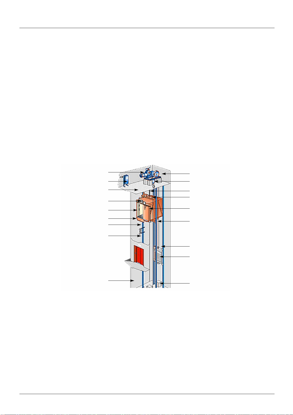
Vocabulary
machine
control panel
machine room
opening/closing system
lift car control panel
base
shaft
guide rails
well
sheave
overspeed detection
traction cables
inspection box on lift car roof
automatic lift car door
safety catch
counterweight guide
counterweight
buffers
Lift command
Electronic card integrating the lift application intelligence: call management, step displays.
The lift command card monitors the slowdown and stop indicators and controls the drive.
Slowdown indicator
Sensor placed at a precise distance (slowdown length) above and below each step.
When the car passes in front of this sensor, the lift command card removes the high speed command (travel speed) and commands a low
speed (lift leveling speed).
Stop indicator
Sensor placed at a precise distance (stop length) above and below each step.
When the car passes in front of this sensor, the lift command card removes t he run command. The car shoul d then st op comfo rtably within
the [Stop length] (StL).
Rollback
Movement of the car when the brake is released. In gearless appli cations where the i nertia at the motor is l arge, the brake rel ease must be
specially controlled to cancel this rollback (using an external weight sensor or the rollback management function).
Jerk
Jerk is a measurement of variations in acceleration. It is often related to comfort (comfort is improved as the jerk is reduced).
BBV19478 11/2011 9
Setup procedure
INSTALLATION
v 1 Consult the Installation Manual
PROGRAMMING
Procedure applicable if the factory configuration, page 11, and use of the
[1.1 LIFT] (LIF-) menu only are sufficient for the application.
b 2 Power up without run command
v If you are using a separate control power
supply, follow the instructions on page
12.
b 3 Select the language, if the drive
has a graphic display terminal
b 4 Configure the menu
[1.1 LIFT] (LIF-)
Tips:
• Before you start programming, complete
the user setting tables, page
325.
• Perform an auto-tuning operation to
optimize performance, page
54.
• If you get lost, return to the factory
settings, page
301.
.
Note: Check that the wiring of the
drive is compatible with its
configuration.
b 5 Start
10 BBV19478 11/2011

Factory configuration
Drive factory settings
The Altivar LIFT is factory-set for the most common operating conditions:
• Motor frequency: 50 Hz
• Normal stop mode on deceleration lift ramp
• Stop mode in the event of a trip: Freewheel
• Deceleration ramp with leveling speed step.
• Motor thermal current = rated drive current
• Standstill injection braking current = 0.7 x rated drive current, for 0.5 seconds
• No automatic starts after a trip
• Switching frequency 8 kHz.
• Logic inputs:
- LI1: forward, LI2: reverse (2 operating directions), 2-wire control on transition
- LI3: Inactive (not assigned)
- LI4: Lift speed
- LI5: Inspection mode
- LI6: Not assigned
• Analog inputs:
- AI1: Speed reference 0 +10 V
- AI2: 0-20 mA, inactive (not assigned)
• Relay R1: no
• Relay R2: Brake control
• Analog output AO1: dO1 (logic output)
If the above values are compatible with the application, the drive can be used without changing the settings.
Option card factory settings
The option card inputs/outputs are not factory-set.
BBV19478 11/2011 11
Setup - Preliminary recommendations
DANGER
UNINTENDED EQUIPMENT OPERATION
• Before turning on and configuring the Altivar LIFT, check that the PWR (POWER REMOVAL) input is deactivated
(at state 0) in order to prevent unintended operation.
• Before turning on the drive, or when exiting the configuration menus, check that the inputs assigned to the run
command are deactivated (at state 0) since they can cause the motor to start immediately.
Failure to follow these instructions will result in death or serious injury.
CAUTION
INCOMPATIBLE LINE VOLTAGE
Before turning on and configuring the drive, ensure that the li ne voltage is compatible with the sup ply voltage range shown
on the drive nameplate. The drive may be damaged if the line voltage is not compatible.
Failure to follow these instructions can result in equipment damage.
CAUTION
• Avoid operating the contactor frequently (premature ageing of the filter capacitors).
• Cycle times < 60 s can result in damage to the precharge resistor.
Failure to follow these instructions can result in equipment damage.
DANGER
UNINTENDED EQUIPMENT OPERATION
• Check that changes made to the settings during operation do not present any danger.
• We recommend stopping the drive before making any changes.
Failure to follow these instructions will result in death or serious injury.
Turning on and configuring the drive
Separate control section power supply
When the drive control section is powered independently of the power section (P24 and 0V terminals), whenever an option card is added
or replaced, only the power section must be supplied with power next time the drive is powered up.
By default the new card would not be recogni zed and i t would b e i mpos sib le to co nfi gure it, thereb y ca usi ng the dri ve to l ock i n fault mode.
Power switching via line contactor
User adjustment and extension of functions
• The display unit and buttons can be used to modify the settings and to extend the functions described in the following pages.
• Return to factory settings is made easy by the [1.12 FACTORY SETTINGS] (FCS-) menu, see page 299
• There are three types of parameter:
- Display: Values displayed by the drive
- Adjustment: Can be changed during operation or when stopped
- Configuration: Can only be modified when stopped and no braking is taking place. Can be displayed during operation.
.
12 BBV19478 11/2011
Setup - Preliminary recommendations
CAUTION
RISK OF DAMAGE TO THE EQUIPMENT
Motor thermal protection will not be provide d by the drive if th e motor current i s less t han 0.2 ti mes the rated drive current.
Provide an alternative means of thermal protection.
Failure to follow these instructions can result in equipment damage.
WARNING
LOSS OF CONTROL
• Identify the precise values of [Nominal car speed] (CSP) and payload [Capacity of the lift] (LCA).
• Check the [Nominal car speed] (CSP) by cal culat ion (See menu [1.1 LIFT] (LIF-), submenu [LIFT DATA] (LdA-)) or
by measurement.
If the values of [Nominal car speed] (CSP) or [Lift capacity] (LCA) are incorrect, the stop lengths ([Deceleration length]
(dEL) and [Stop length] (StL) will not be adhered to.
The speed loop preset will not be adapted to the application (risk of instability and lift car slipping).
Failure to follow these instructions will result in death or serious injury.
Starting
Important:
• In factory settings mode, the motor can only be supplied wit h power once the “forward”, “reverse” an d “DC injection st op” commands
have been reset:
- On power-up or a manual detected fault reset or after a stop command.
If they have not been reset, the drive will display "nSt" but will not start.
• If the automatic restart function has been configured ([Automatic restart] (Atr) parameter in the [1.8-FAULT MANAGEMENT] (FLt-)
menu, see page 273
Test on a low power motor or without a motor
• In factory settings mode, [Output Phase Loss] (OPL) detection page 276 is active (OPL = YES). To check the drive in a test or
maintenance environment without having to switch to a moto r with the same rating as the drive (part icularly useful in the case of high
power drives), deactivate [Output Phase Loss] (OPL = nO).
), these commands are taken into account without a reset being necessary.
Use of the LIFT menu
BBV19478 11/2011 13
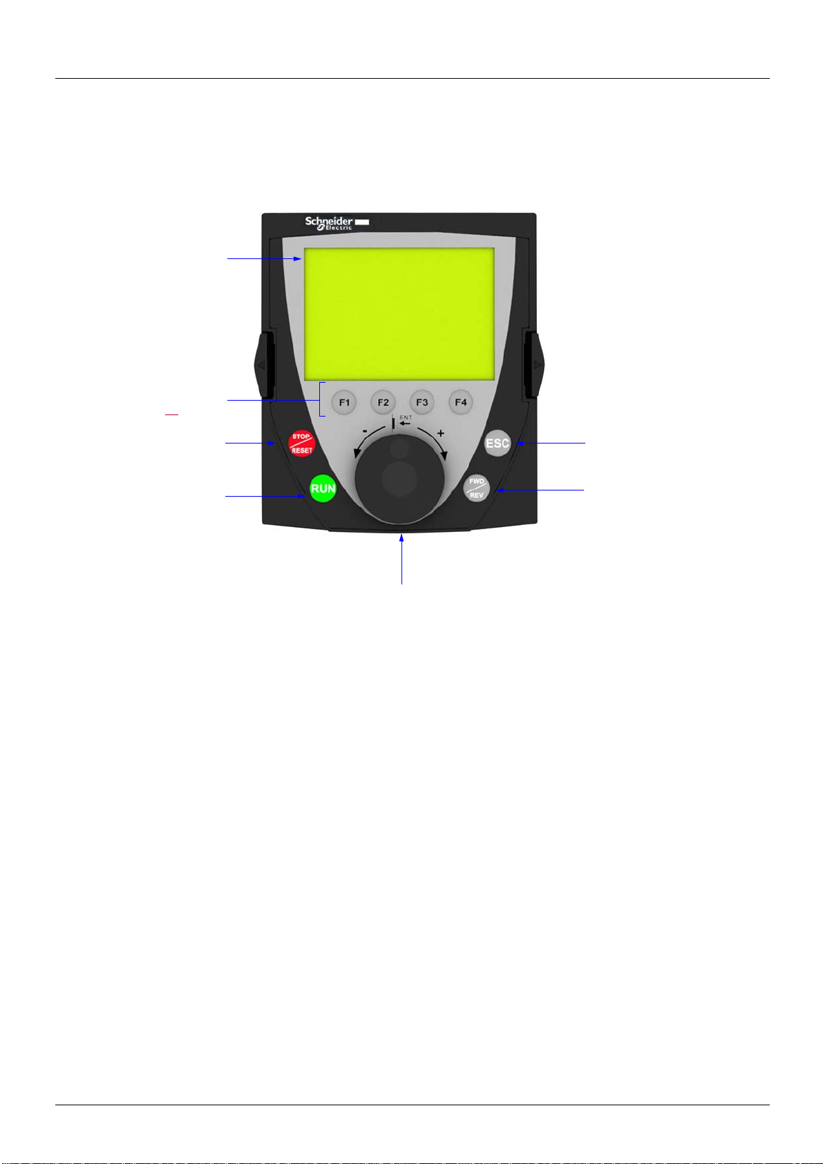
Graphic terminal
1 Graphic display
2 Function keys
F1, F2, F3, F4,
see page 15
.
3 STOP/RESET
button
4 RUN button
5 Navigation button:
• Press (ENT): - To save the current value
- To enter the selected menu or parameter
• Turn CW/
CCW:
- To increment or decrement a value
- To go to the next or previous line
- To increase or decrease the reference if control via
the display terminal is activated
7 ESC key: Aborts a value, a
parameter or a menu to return
to the previous selection
6 Button for reversing the directi on
of rotation of the motor
The graphic terminal is optional. The graphic termin al is removabl e and can be loc ated remotel y (on the door o f an enclosure, for example)
using the cables and accessories available as options (see catalog).
Description of the terminal
Note: Buttons 3, 4, 5 and 6 can be used to control the drive directly, if control via the display t erminal is activated.
14 BBV19478 11/2011
Graphic terminal
F1 F2 F3 F4
RDY Term +0.00Hz 0A
1 DRIVE MENU
1.1 LIFT
1.2 MONITORING
1.3 SETTINGS
1.4 MOTOR CONTROL
1.5 INPUTS / OUTPUTS CFG
Code << >> Quick
1
2
3
4
6
5
• Code F1
•HELP F1
• << F2
• >> F3
• Quick F4
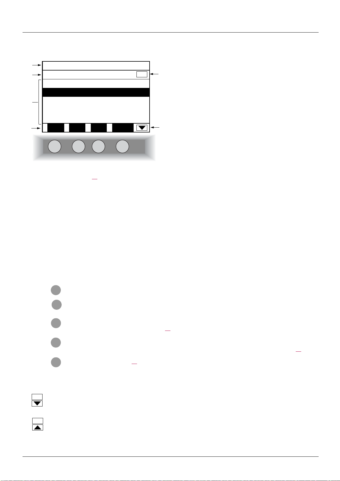
Description of the graphic screen
1. Display line. Its content can be configured; the factory settings show:
• The drive state (see page 16
• The active control channel:
- Term: Terminals
- HMI: Graphic terminal
- MDB: Integrated Modbus
- CAN: Integrated CANopen
- NET: Communication card
- APP: Controller Inside card
• Frequency reference
• Current in the motor
)
2. Menu line. Indicates the name of the current menu or submenu.
3. Menus, submenus, parameters, values, bar charts, etc., are displayed in drop-down window format on a maximum of 5 lines.
The line or value selected by the navigation button is displayed in reverse video.
4. Section displaying the functions assigned to the F1 to F4 keys and aligned with them, for example:
The function keys are dynamic and contextual.
Other functions (application functions) can be assigned to these keys via the [1.6 COMMAND] menu.
5. Indicates that there are no more levels below this display window.
Indicates that there are more levels below this display window.
6. Indicates that this display window does not scroll further up.
Indicates that there are more levels above this display window.
: Displays the code of the selected parameter, i.e., the code corresponding to the 7-segment display.
: Contextual help
: Navigate horizontally to the left, or go to previous menu/submenu or, for a value, go to the next digit up, displayed
in reverse video (see the example on page 17
: Navigate horizontally to the right or go to next menu/submenu (going to the [2 ACCESS LEVEL] menu in this
example) or, for a value, go to the next digit down, displayed in reverse video (see the example on page 17
: Quick navigation, see page 21.
).
).
BBV19478 11/2011 15

Graphic terminal
Drive state codes:
- ACC: Acceleration
- CLI: Current limita ti on
- CTL: Controlled stop on input phase loss
- DCB: DC injection braking in progress
-DEC: Deceleration
- FLU: Motor fluxing in progress
-FST: Fast stop
- NLP: No line power (no line supply on L1, L2, L3)
- NST: Freewheel stop
- OBR: Auto-adapted deceleration
- PRA: Power Removal function active (drive locked)
- RDY: Drive ready
- RUN: Drive running
- SOC: Controlled output cut in progress
- TUN: Auto-tuning in progress
- USA: Undervoltage alarm
- ASA: Measurement of the phase-shift angle in progress
16 BBV19478 11/2011
Graphic terminal
RDY Term +0.00Hz 0A
5 LANGUAGE
English
Français
Deutsch
Español
Italiano
<< >> Quick
Chinese
Russian
Turkish
PARAMETER SELECTION
1.3 SETTINGS
Ramp increment
Acceleration
Deceleration
Acceleration 2
Deceleration 2
Edit
RDY Term +0.00Hz 0A
Acceleration
9.51 s
Min = 0.01 Max = 99.99
<< >> Quick
>>
RDY Term +0.00Hz 0A
Acceleration
9.51 s
Min = 0.01 Max = 99.99
<< >> Quick
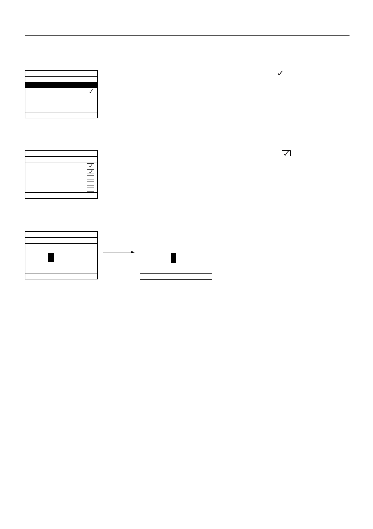
Example configuration windows:
When only one selection is possible, the selection made is indicated by .
E.g. Only one language can be chosen.
When multiple selection is possible, the selections made are indi cated by .
E.g. A number of parameters can be chosen to form the [USER MENU].
Example configuration window for one value:
The << and >> arrows (keys F2 and F3) are used to select the digit to be modified, and the navigation button is rotated to increase or
decrease this number.
BBV19478 11/2011 17
Graphic terminal
ATV71LD10N4Z
10A 380/480V
Config. n°1
5 LANGUAGE
English
Français
Deutsch
Español
Italiano
Chinese
Russian
Turkish
RDY Term 0.00m/s 0.0A
2 ACCESS LEVEL
Basic
Standard
Advanced
Expert
RDY Term 0.00 m/s 0.0 A
1.1 LIFT
International unit
LIFT CONFIGURATION
LIFT OPTIMIZATION
LIFT FUNCTIONS
MONITORING
Code << >> Quick
RDY Term 0.00 m/s 0.0 A
MAIN MENU
1 DRIVE MENU
2 ACCESS LEVEL
3 OPEN / SAVE AS
4 PASSWORD
5 LANGUAGE
Code Quick
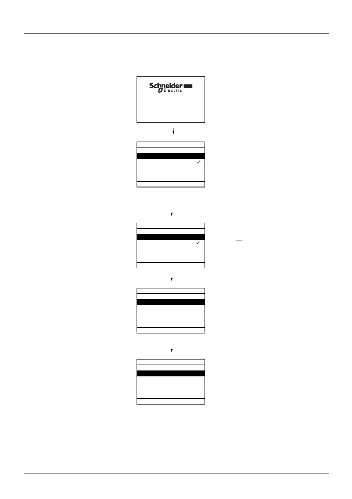
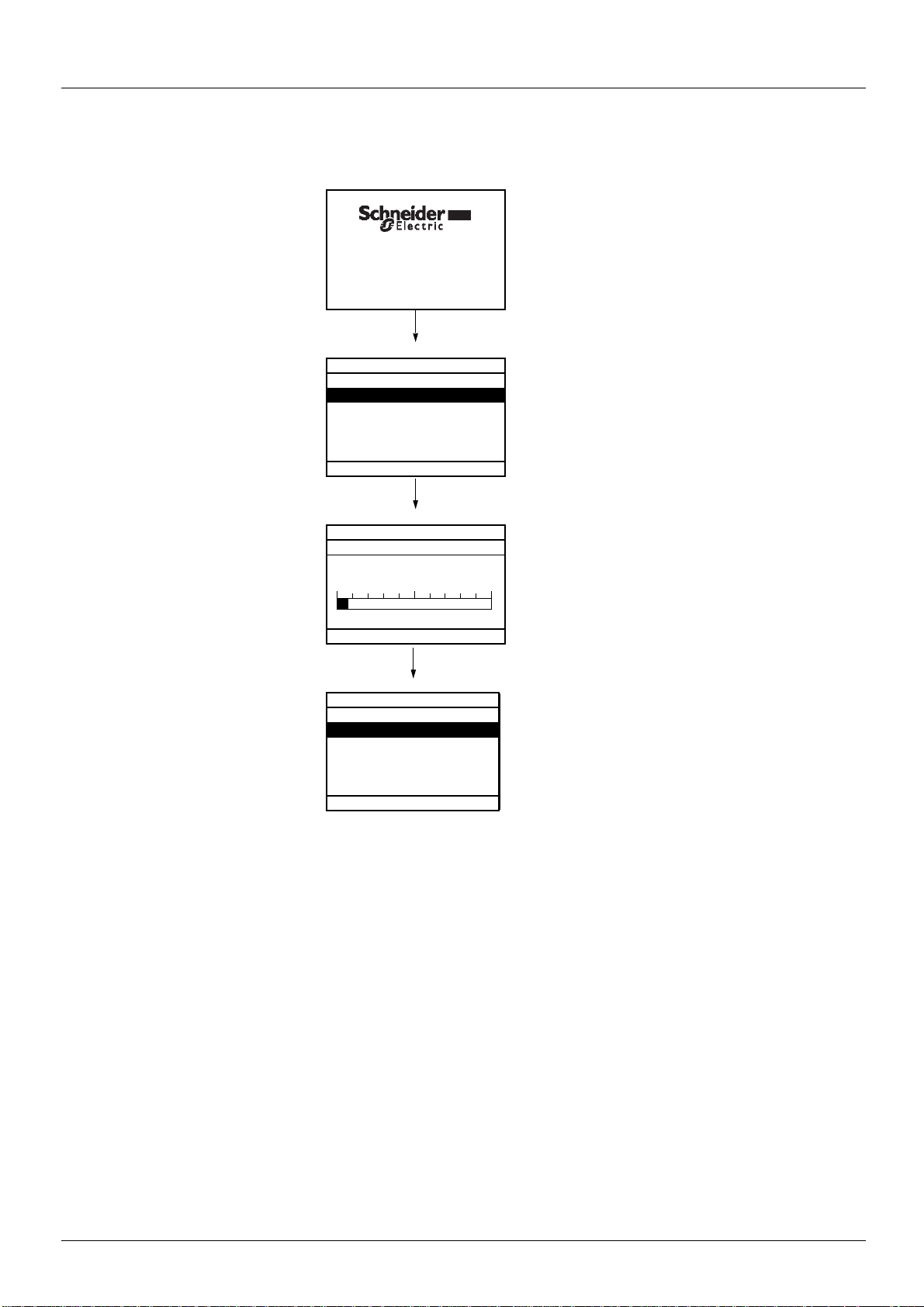
First power-up - [5. LANGUAGE] menu
The first time the drive is powered up, the user will automatically be guided through the menus as far as the [1.1. LIFT] submenu.
The parameters in this submenu must be configured and auto-tuning performed before the motor is started up.
Display for 3 seconds following power-up
3 seconds
Automatically switches to [5 LANGUAGE]
menu 3 seconds later.
Select the language and press ENT.
Switches to [2 ACCESS LEVEL] menu
(see page 27
)
Select the access level and press ENT.
Switches to [1.1 LIFT]
(see page 23
)
ESC
ESC
Press ESC twice to return to [MAIN MENU]
18 BBV19478 11/2011
Graphic terminal
3 seconds
10 seconds
ENT or ESC
ATV71LD10N4Z
10A 380/480V
Config. n°1
RDY Term 0.00 m/s 0.0 A
1.1 LIFT
LIFT CONFIGURATION
LIFT OPTIMIZATION
LIFT FUNCTIONS
MONITORING
International unit
Code << >> Quick
RDY Term 2.00 m/s 0.0 A
Elevator Speed
Min=0.00 Max=327.67
Quick
RDY Term 0.00 m/s 0.0 A
MAIN MENU
1 DRIVE MENU
2 ACCESS LEVEL
3 OPEN / SAVE AS
4 PASSWORD
5 LANGUAGE
Code Quick
2.00 m/s
Subsequent power ups
Switches to [1.1. LIFT] 3 seconds later.
If no operator inputs are made, switches to "Display"
automatically 10 seconds later (the display will vary
depending on the selected configuration).
Users can return to [MAIN MENU] by pressing
ENT or ESC.
BBV19478 11/2011 19
Graphic terminal
RDY Term +0.00Hz 0A
1 DRIVE MENU
1.1 LIFT
1.2 MONITORING
1.3 SETTINGS
1.4 MOTOR CONTROL
1.5 INPUTS / OUTPUTS CFG
Code << >> Quick
ENT
ESC
RDY Term +0.00Hz 0A
1.1 LIFT
LIFT CONFIGURATION
LIFT OPTIMIZATION
LIFT FUNCTIONS
MONITORING
International unit
Code << >> Quick
ENT
ENT or
ESC
RDY Term +0.00Hz 0A
LIFT CONFIGURATION
I/O ASSIGNMENT
ENCODER DATA
MOTOR DATA
LIFT DATA
Code << >> Quick
ENT
ENT or
ESC
RDY Term +0.00Hz 0A
LIFT DATA
Nominal car speed 1.00 m/s
Capacity of the lift 400 kg
Car weight Auto
Counterweight Auto
Max. Acceleration 0.5 m/s²
Code << >> Quick
ENT
ENT or
ESC
RDY Term +0.00Hz 0A
Nominal car speed
1.50 m/s
Min = 0.01 Max = 10.00
<< >> Quick
Programming: Example of accessing a parameter
Accessing the nominal car speed
Note:
• To select a parameter:
- Turn the navigation button to scroll vertically.
• To modify a parameter:
- Use the << and >> keys (F2 and F3) to scroll horizontally and select the digit to be modified (the selected di git chan ges to white
on a black background).
- Turn the navigation button to modify the digit.
• To cancel the modification:
-Press ESC.
• To save the modification:
- Press the navigation button (ENT).
20 BBV19478 11/2011
Graphic terminal
RDY Term +0.00Hz 0A
1.4 MOTOR CONTROL
Standard mot. freq: 50Hz IEC
Motor control type: SVC U
Max frequency: 60 Hz
Output Ph rotation: ABC
Sinus filter: no
Code << >> Quick
ENT
RDY Term +0.00Hz 0A
QUICK NAVIGATION
RETURN TO MAIN MENU
DIRECT ACCESS TO...
10 LAST MODIFICATIONS
GOTO MULTIPOINT SCREEN
Code
See page 317
RDY Term +0.00Hz 0A
MAIN MENU
1 DRIVE MENU
2 ACCESS LEVEL
3 OPEN / SAVE AS
4 PASSWORD
5 LANGUAGE
Code Quick
RDY Term +0.00Hz 0A
DIRECT ACCESS TO...
1.3
SETTINGS
<< >>
ENT
RDY Term +0.00Hz 0A
1.3 SETTINGS
Ramp increment: 01
Acceleration 9.51 s
Deceleration: 9.67 s
Acceleration 2: 12.58 s
Deceleration 2 : 13.45 s
Code << >> Quick
RDY Term +0.00Hz 0A
10 LAST MODIFICATIONS
Acceleration: 10 s
ENA prop.gain: 1.2
Rated mot. current: 15 A
Preset speed 4: 20 Hz
Preset speed 5: 30 Hz
Code
ESC
ENT
RDY Term +0.00Hz 0A
Rated mot. current
15.0 A
<< >>
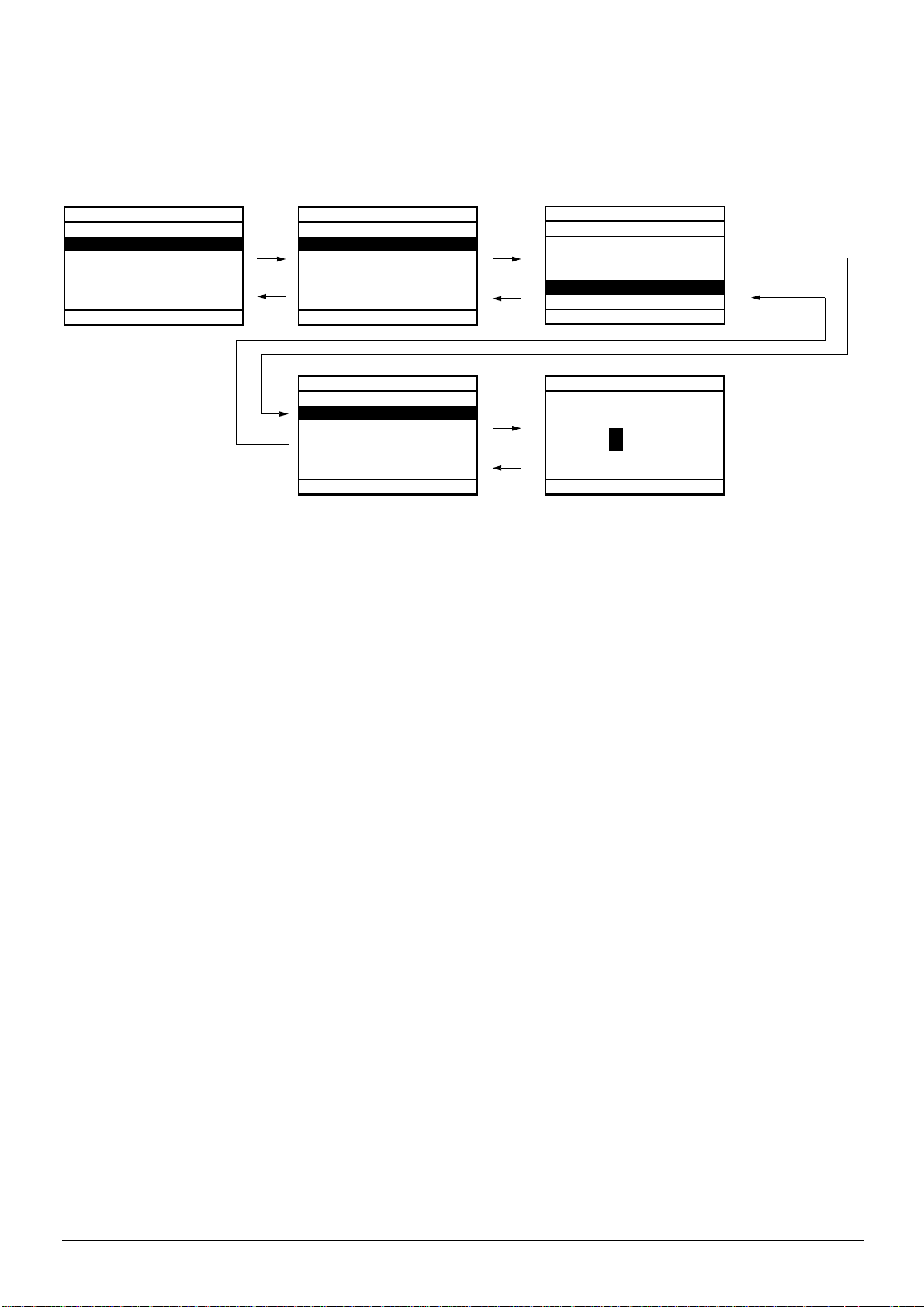
Quick navigation
If the "Quick" function is displayed above the F4 key, you can gain quick access to a parameter from any screen.
E.g.
Press F4 to access the Quick screen, which contains
4 selection options.
• [HOME]: Return to [MAIN MENU].
• [DIRECT ACCESS TO...] : Opens the direct access window, which
will contain the text "1". The function keys << and >> (F2 and F3)
can be used to select each of the numbers and the navigation
button to increment or decrement the numbers: 1.3 in the example
below.
• [10 LAST MODIFICATIONS]: Opens a window in which the last
10 parameters modified can be accessed directly.
BBV19478 11/2011 21
Graphic terminal
RDY Term +0.00Hz 0A
MAIN MENU
1 DRIVE MENU
2 ACCESS LEVEL
3 OPEN / SAVE AS
4 PASSWORD
5 LANGUAGE
Code Quick
6 MONITORING CONFIG.
7 DISPLAY CONFIG.
8 International unit
RDY Term +0.00Hz 0A
1 DRIVE MENU
1.1 LIFT
1.2 MONITORING
1.3 SETTINGS
1.4 MOTOR CONTROL
1.5 INPUTS / OUTPUTS CFG
Code << >> Quick
1.6 COMMAND
1.7 APPLICATION FUNCT.
1.8 FAULT MANAGEMENT
1.9 COMMUNICATION
1.10 DIAGNOSTICS
1.11 IDENTIFICATION
1.12 FACTORY SETTINGS
1.13 USER MENU
1.14 CONTROL. INSIDE CARD
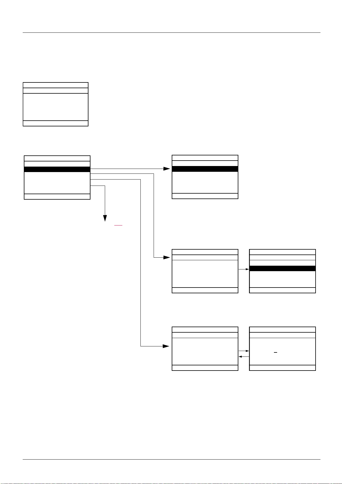
[MAIN MENU] - Menu mapping
Content of [MAIN MENU] menus
[1 DRIVE MENU] See next page
[2 ACCESS LEVEL] Defines which menus can be accessed (level of complexity)
[3 OPEN / SAVE AS] Can be used to save and retrieve drive configuration files
[4 PASSWORD] Provides password protection for the configuration
[5 LANGUAGE] Language selection
[6 MONITORING CONFIG.] Customization of information displayed on the graphic display terminal during operation
[7 DISPLAY CONFIG.] • Customization of parameters
• Creation of a customized user menu
• Customization of the visibility and protection mechanisms for menus and parameters
[8 International unit] • Provides the possibility to work with metric units or with imperial units for lift parameters.
See page 119.
22 BBV19478 11/2011

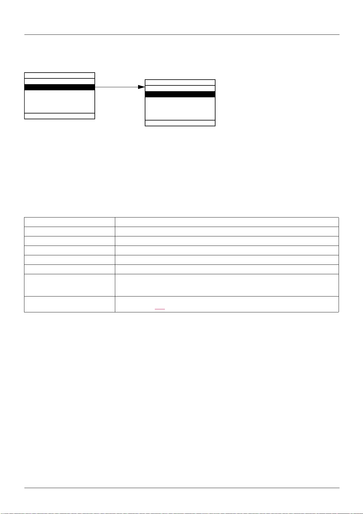
Graphic terminal
[1 DRIVE MENU]
RDY Term +0.00Hz 0A
1.1 LIFT
1.2 MONITORING
1.3 SETTINGS
1.4 MOTOR CONTROL
1.5 INPUTS / OUTPUTS CFG
1.6 COMMAND
1.7 APPLICATION FUNCT.
1.8 FAULT MANAGEMENT
1.9 COMMUNICATION
1.10 DIAGNOSTICS
1.11 IDENTIFICATION
1.12 FACTORY SETTINGS
1.13 USER MENU
1.14 CONTROL. INSIDE CARD
Content of [1. DRIVE MENU] menus:
[1.1 LIFT]: Lift menu
[1.2 MONITORING]: Visualization of current, motor and input/output values
[1.3 SETTINGS]: Accesses the adjustment parameters, which can be modified during operation
[1.4 MOTOR CONTROL ]: Moto r parameters (motor nameplate, auto-tuning, switching frequency, control algorithms, etc.)
[1.5 INPUTS / OUTPUTS CFG]: I/O configuration (scaling, filtering, 2-wire control, 3-wire control, etc.)
[1.6 COMMAND]: Configuration of command and reference channels (graphic displ ay t erminal , t erminals , bu s, e tc.)
[1.7 APPLICATION FUNCT.] : Configuration of application functions (e.g., preset speeds, PID, brake control , etc. )
[1.8 FAULT MANAGEMENT]: Configuration of fault management
[1.9 COMMUNICATION]: Communication parameters (fieldbus)
[1.10 DIAGNOSTICS]: Motor/drive diagnostics
[1.11 IDENTIFICATION]: Identifies the drive and internal options
[1.12 FACTORY SETTINGS]: Access to configuration files and return to factory settings
[1.13 USER MENU]: Specific menu set up by t he user in the [7. DISPLAY CONFIG.] menu
[1.14 CONTROL. INSIDE CARD]: Configuration of optional Controller Inside card
1 DRIVE MENU
Code << >> Quick
BBV19478 11/2011 23
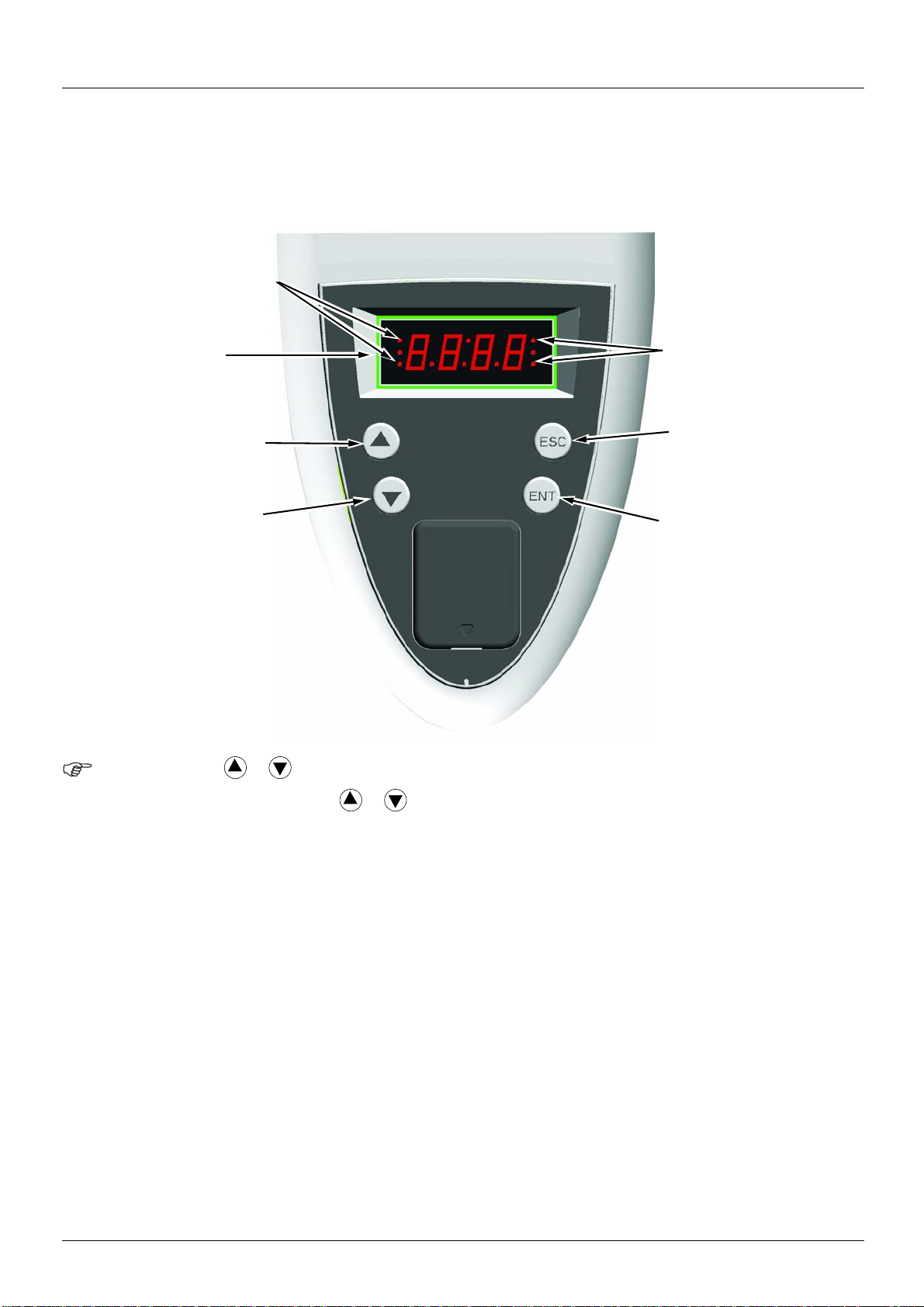
Integrated display terminal
• Four 7-segment
displays
• Enters a menu or a
parameter, or saves the
displayed parameter or
value
• Exits a menu or parameter,
or aborts the displayed
value to return to the
previous value in the
memory
• Goes to the next menu
or parameter, or
decreases the
displayed value
• 2 CANopen status LEDs
• 2 Modbus status LEDs
• Returns to the previous
menu or parameter, or
increases the
displayed value
Note:
Altivar LIFT features an integrated display terminal with a 7-segment 4-digit di splay. The graphic displ ay terminal described on the p revious
pages can also be connected to this drive as an option.
Functions of the display and the keys
• Pressing or does not store the selection.
• Press and hold down (>2 s) or to scroll through the data quickly.
Save and store the selection: ENT
The display flashes when a value is stored.
Normal display, with no detected fault present and no startup:
- 43.0: Display of the parameter selected in the SUP menu (default selection: Lift speed).
- CLI: Current limita ti on.
- CtL: Controlled st op on in pu t phase loss.
- dCb: DC injection braking in progress.
- FLU: Motor fluxing in progress.
- FSt: Fast stop.
- nLP: No line power (no line supply on L1, L2, L3).
- nSt: Freewheel stop.
- Obr: Auto-adapted deceleration.
- PrA: Power Removal function active (drive locked).
- rdY: Drive ready.
- SOC: Controlled output cut in progress.
- tUn: Auto-tuning in progress.
- USA: Undervoltage alarm.
- ASA: Measurement of the phase-shift angle in progress.
The display flashes to indicate the presence of a detected fault.
24 BBV19478 11/2011
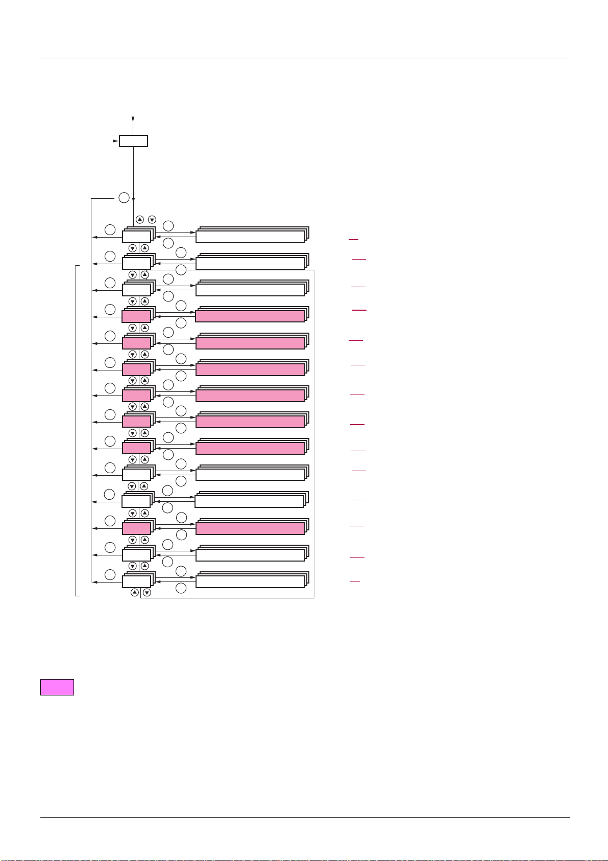
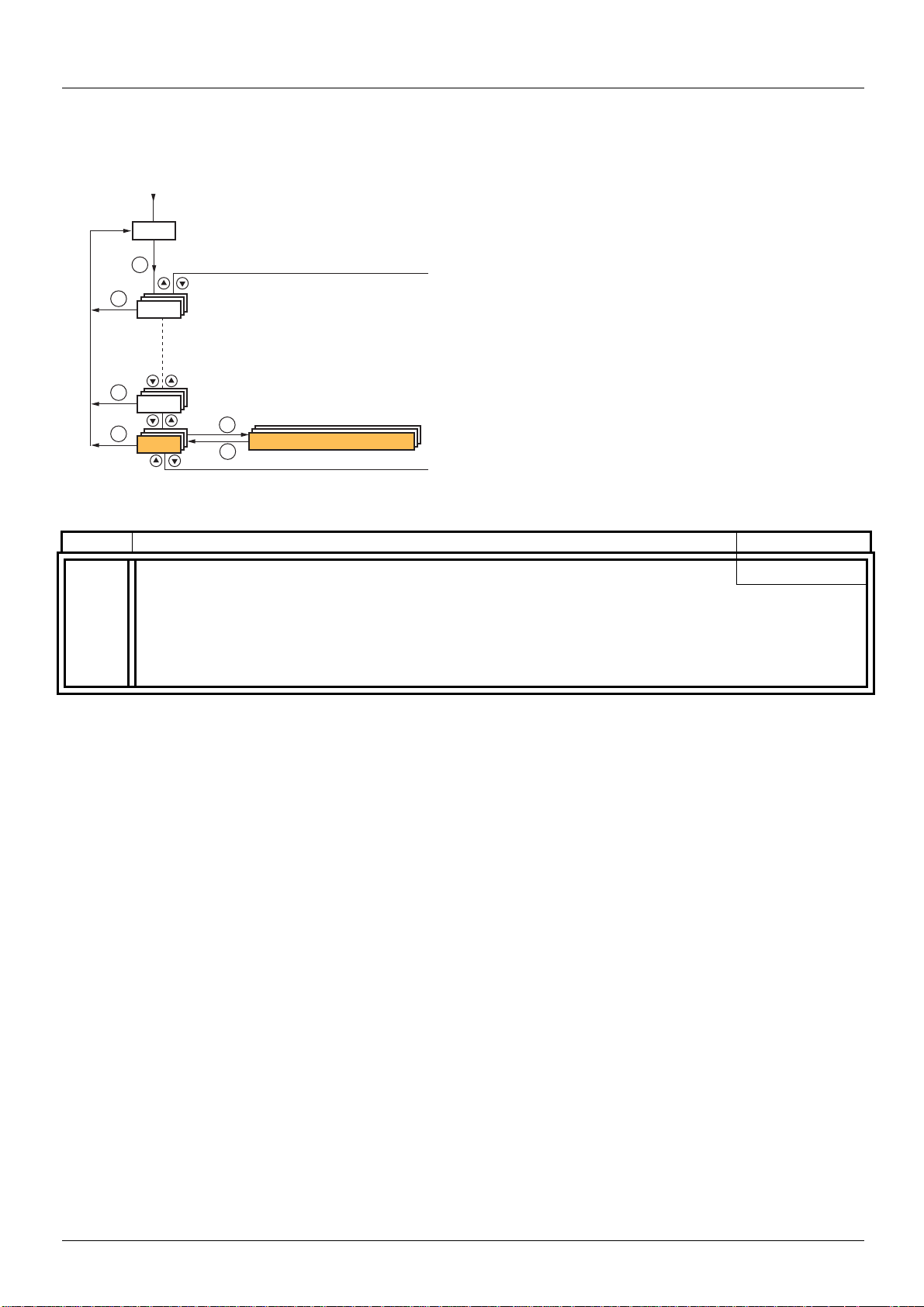
Integrated display terminal
XXX
CtL-
FUn-
LIF-
I-O-
SEt-
SUP-
ESC
ESC
ESC
ESC
ESC
ESC
ESC
ESC
ENT
ENT
ESC
ENT
ESC
ENT
ESC
ENT
ESC
ENT
ESC
ENT
ESC
ENT
ESC
FCS-
LAC-
CON-
FLt-
ESC
ESC
ESC
ESC
ENT
ESC
ENT
ESC
ENT
ESC
ENT
ESC
ENT
ESC
PLC-
ESC
ENT
ESC
drC-
COd-
USr-
ESC
ENT
ESC
Displays the state of the drive
SETTINGS
APPLICATION FUNCT.
INPUTS / OUTPUTS CFG
FAULT MANAGEMENT
LIFT
Menus
MONITORING
MOTOR CONTROL
COMMAND
Turn on
FACTORY SETTINGS
PASSWORD
ACCESS LEVEL
COMMUNICATION
(page 133) Adjustment parameters, can be modified during
operation
(page 216
) Configuration of application functions (e.g., preset
speeds, brake control, etc.)
(page 173
) I/O configuration (scaling, filtering, 2-wire control,
3-wire control, etc.)
(page 268
) Configuration of fault management
(page 33
) Lift menu
(page 124
) Visualization of current, motor and input/output
values
(page 145
) Motor parameters (motor nameplate, auto-tuning,
switching frequency, control algorithms, etc.)
(page 203
) Configuration of command and reference channels
(graphic display terminal, terminals, bus, etc.)
(page 299
) Access to configuration files and return to factory
settings
(page 306
)
(page 27
)
(page 291
) Communication parameters (fieldbus)
(page 302
) Specific menu, set up by the user using the graphic
display terminal.
USER MENU
CONTROL. INSIDE CARD
(page 303
) Menu for the Controller Inside card, if present.
Accessing menus
A dash appears after menu and submenu codes to differentiate them from parameter codes.
Examples: FUn- menu, ACC parameter.
BBV19478 11/2011 25
The grayed-out menus may not be accessible depending on the control access (LAC) configuration.
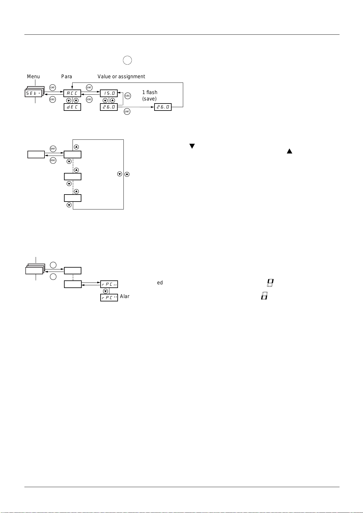
Integrated display terminal
ENT
ACC 15.0
ENT
ESC
ENT
ESC
26.0 26.0
ESC
dEC
ENT
SEt-
Menu Value or assignment
1 flash
(save)
Parameter
(Next parameter)
ENT
ESC
1
st
n
th
last
Menu
ENT
ESC
I-O-
Alarm not selected
Alarm selected
Accessing menu parameters
Save and store the displayed selection:
The display flashes when a value is stored.
All the menus are "drop-down" type menus, which means that after the last pa rameter, if
you continue to press , you will return to the fi rst p arameter and, conver sely, you c an
switch from the first parameter to the last parameter by pressing .
Selection of multiple assignments for one parameter
E.g. List of group 1 alarms in [INPUTS / OUTPUTS CFG] (I-O-)
menu
A number of alarms can be selected by "checking" them as
follows.
The digit on the right indicates: selected,
not selected.
The same principle is used for all multiple select ions.
26 BBV19478 11/2011
[2. ACCESS LEVEL] (LAC-)
RDY Term +0.00Hz 0A
2 ACCESS LEVEL
Basic
Standard
Advanced
Expert
<< >> Quick
RDY Term +0.00Hz 0A
MAIN MENU
1 DRIVE MENU
2 ACCESS LEVEL
3 OPEN / SAVE AS
4 PASSWORD
5 LANGUAGE
Code << >> Quick
8 International unit
RDY Term +0.00Hz 0A
1. DRIVE MENU
1.1 LIFT
1.2 MONITORING
1.3 SETTINGS
1.11 IDENTIFICATION
1.12 FACTORY SETTINGS
Code << >> Quick
1.13 USER MENU
RDY Term +0.00Hz 0A
MAIN MENU
1 DRIVE MENU
2 ACCESS LEVEL
3 OPEN / SAVE AS
4 PASSWORD
5 LANGUAGE
Code Quick
6 MONITORING CONFIG.
8 International unit
RDY Term +0.00Hz 0A
1 DRIVE MENU
1.1 LIFT
1.2 MONITORING
1.3 SETTINGS
1.4 MOTOR CONTROL
1.5 INPUTS / OUTPUTS CFG
Code << >> Quick
1.6 COMMAND
1.7 APPLICATION FUNCT.
1.8 FAULT MANAGEMENT
1.9 COMMUNICATION
1.10 DIAGNOSTICS
1.11 IDENTIFICATION
1.12 FACTORY SETTINGS
1.13 USER MENU
1.14 CONTROL. INSIDE CARD
RDY Term +0.00Hz 0A
MAIN MENU
1 DRIVE MENU
2 ACCESS LEVEL
3 OPEN / SAVE AS
4 PASSWORD
5 LANGUAGE
Code Quick
6 MONITORING CONFIG.
7 DISPLAY CONFIG.
8 International unit
RDY Term +0.00Hz 0A
MAIN MENU
1 DRIVE MENU
2 ACCESS LEVEL
3 OPEN / SAVE AS
4 PASSWORD
5 LANGUAGE
Code Quick
6 MONITORING CONFIG.
7 DISPLAY CONFIG.
8 International unit
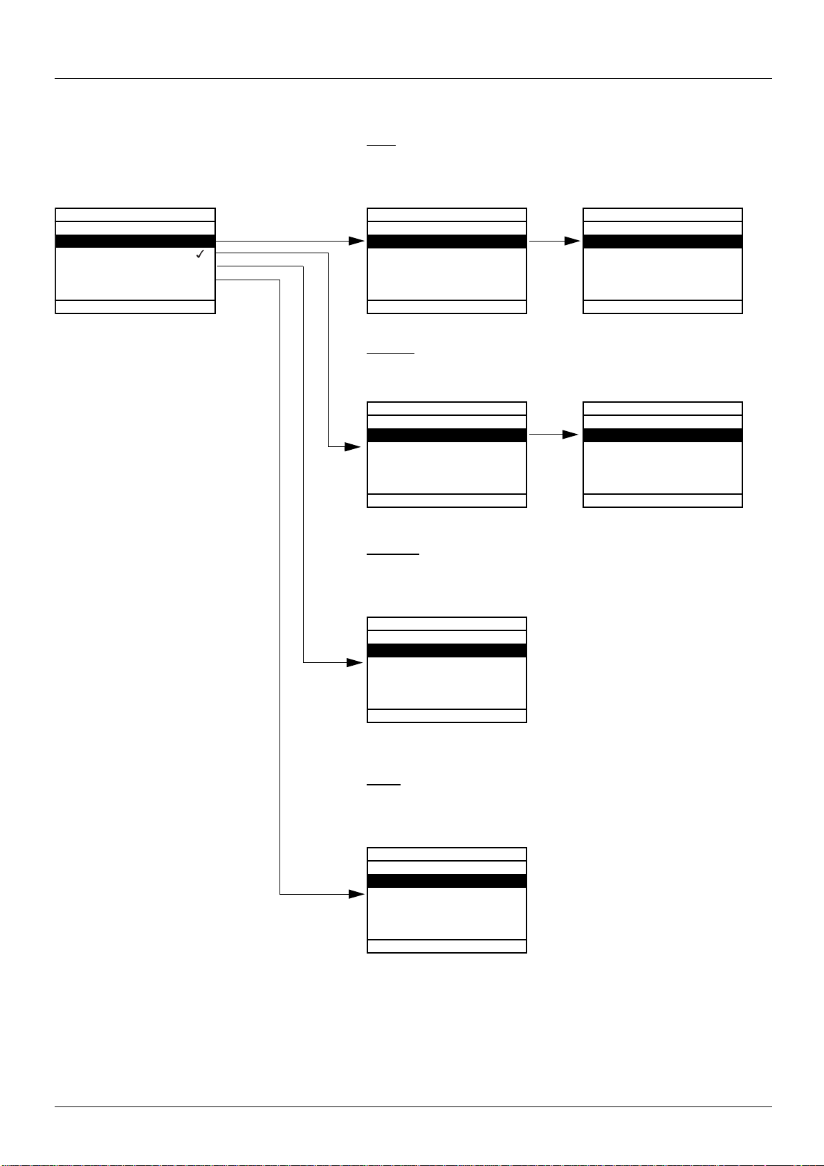
With graphic display terminal
Basic
Access to 5 menus only, and access to 6 submenus only in the
[1. DRIVE MENU] menu.
A single function can be assigned to each input.
Standard
This is the factory-set level. Access to all menus.
A single function can be assigned to each input.
BBV19478 11/2011 27
Advanced
Access to all menus and submenus.
Several functions can be assigned to
each input.
Expert
Access to all menus and submenus as for [Advanced] level, and access to
additional parameters.
Several functions can be assigned to each input.
[2. ACCESS LEVEL] (LAC-)
XXX
LIF-
ESC
ESC
ENT
LAC-
ESC
ENT
ESC
COd-
Displays the state of the drive
Turn on
With integrated display terminal:
ACCESS LEVEL
Code Name/Description Factory setting
LAC-
bAS
• bAS: Limited access to SIM, SUP, SEt, FCS, USr, COd and LAC menus. A single f unction can be assigned to each
Std
input.
Std
AdU
Epr
• Std: Access to all menus on the integrated display terminal. A single fun ction can be assigned to each input.
• AdU: Access to all menus on the integrated display terminal. Several functions can be assigned to each input.
• EPr: Access to all menus on the integrated display te rminal and access to additional p arameters. Several functions
can be assigned to each input.
28 BBV19478 11/2011
[2. ACCESS LEVEL] (LAC-)
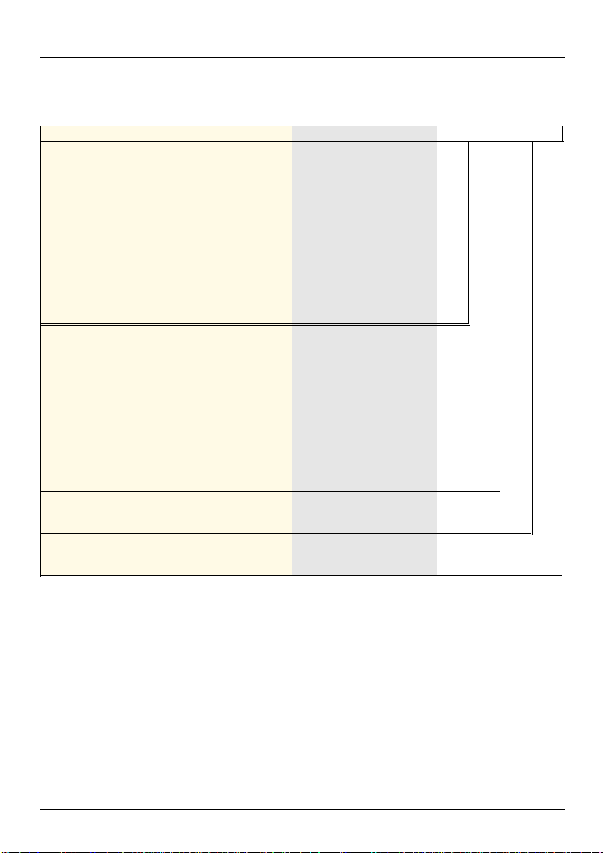
Comparison of the menus that can be accessed on the graphic display terminal/integrated display terminal
Graphic terminal Integrated Display Terminal Access Level
[2 ACCESS LEVEL] LAC- (Access level)
[3 OPEN/SAVE AS] [4 PASSWORD] COd- (Password)
[5 LANGUAGE] [1 DRIVE MENU] [1.1 LIFT] LIF- (Lift)
[1.2 MONITORING] SUP-(Monitoring)
[1.3 SETTINGS] SEt- (Settings)
[1.11 IDENTIFICATION] [1.12 FACTORY SETTINGS] FCS- (Factory settings)
[1.13 USER MENU] USr- (User menu)
A single function can be assigned to each input. A single function can be assigned to
each input.
[1.4 MOTOR CONTROL] drC- (Motor control)
[1.5 INPUTS / OUTPUTS CFG] I-O- (I/O configuration)
[1.6 COMMAND] CtL- (Command)
[1.7 APPLICATION FUNCT.] FUn- (Application functions)
[1.8 FAULT MANAGEMENT] FLt- (Fault management)
[1.9 COMMUNICATION] COM- (Communication)
[1.10 DIAGNOSTICS] [1.14 CONTROL. INSIDE CARD] (1) PLC- (Controller Inside card) (1)
[6 MONITORING CONFIG.] -
A single function can be assigned to each input. A single function can be assigned to
each input.
[7 DISPLAY CONFIG.] -
Several functions can be assigned to each input. Several functions can be assigned
to each input.
Expert parameters Expert parameters
Several functions can be assigned to each input. Several functions can be assigned
to each input.
Basic bAS
Standard Std (factory setting)
Advanced AdU
Expert EPr
(1)Can be accessed if the Controller Inside card is present.
BBV19478 11/2011 29
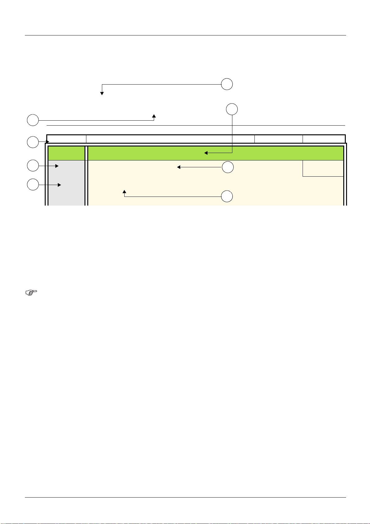
Structure of the parameter tables
5
2
3
1
4
6
8
7
1. Name of menu on 4-digit 7-segment display.
2. Submenu code on 4-digit 7-segment display.
3. Parameter code on 4-digit 7-segment display.
4. Parameter value on 4-digit 7-segment display.
5. Name of menu on graphic display terminal.
6. Name of submenu on graphic display terminal.
7. Name of parameter on graphic display terminal
8. Value of parameter on graphic display terminal
The parameter tables in the descriptio ns of the various menus can be used wit h both the graphi c display terminal an d the integrated display
terminal. They therefore contain information for these two terminals in accordance with the description below.
E.g.
[1.7 APPLICATION FUNCT.] (FUn-)
Code Name/Description Adjustment range: Factory setting
rEF-
rCb
Fr1
Fr1b
Note:
• The text in square brackets [ ] indicates what you will see on the graphic display terminal.
[REFERENCE SWITCH.]
M [Ref 1B switching]
v [ch1 active] (Fr1): No switching, [Ref.1 channel] (Fr1) active
v [ch1B active] (Fr1b): No switching, [Ref.1B channel] (Fr1b) active
[ch1 active]
(Fr1)
30 BBV19478 11/2011
 Loading...