

Page 1
Altivar 61
Transition manual
Migration from ATV38 V ATV61
Page 2

This document has been designed to assist you when replacing an Altivar 38 with an Altivar 61 version V1.1 ie01 or later.
Scope of application:
- Variable-torque applications
- Replacement of Altivar 38 on three-phase 380 V 460 V ranges
The Altivar 61 and its various options or accessories can be selected on the basis of the hardware configuration used on the Altivar 38.
The fundamental expansions offered by the Altivar 61 affect features such as the number of I/O, application functions, operating
temperature, etc.
This manual also outlines assembly, installation and wiring instructions.
Migrating an Altivar 38 to an Altivar 61 software configuration is made simple by the use of the PowerSuite v2.20 software workshop.
Page 3

Table of contents
Determining catalog numbers____________________________________________________________________________________ 6
Choosing the Altivar 61 catalog number _____________________________________________________________________ 6
Selecting the power circuit options _________________________________________________________________________ 7
Mounting accessories ___________________________________________________________________________________ 8
Control circuit options ___________________________________________________________________________________ 9
Selecting I/O extension cards (VW3A58201, VW3A58202) _____________________________________________________ 10
Selecting communication channels ________________________________________________________________________ 12
Drive implementation _________________________________________________________________________________________ 14
Installation ___________________________________________________________________________________________ 14
Comparison of dimensions ______________________________________________________________________________ 17
Mounting the RFI filter __________________________________________________________________________________ 20
NEMA mounting kits ___________________________________________________________________________________ 24
Separate control card power supply _______________________________________________________________________ 26
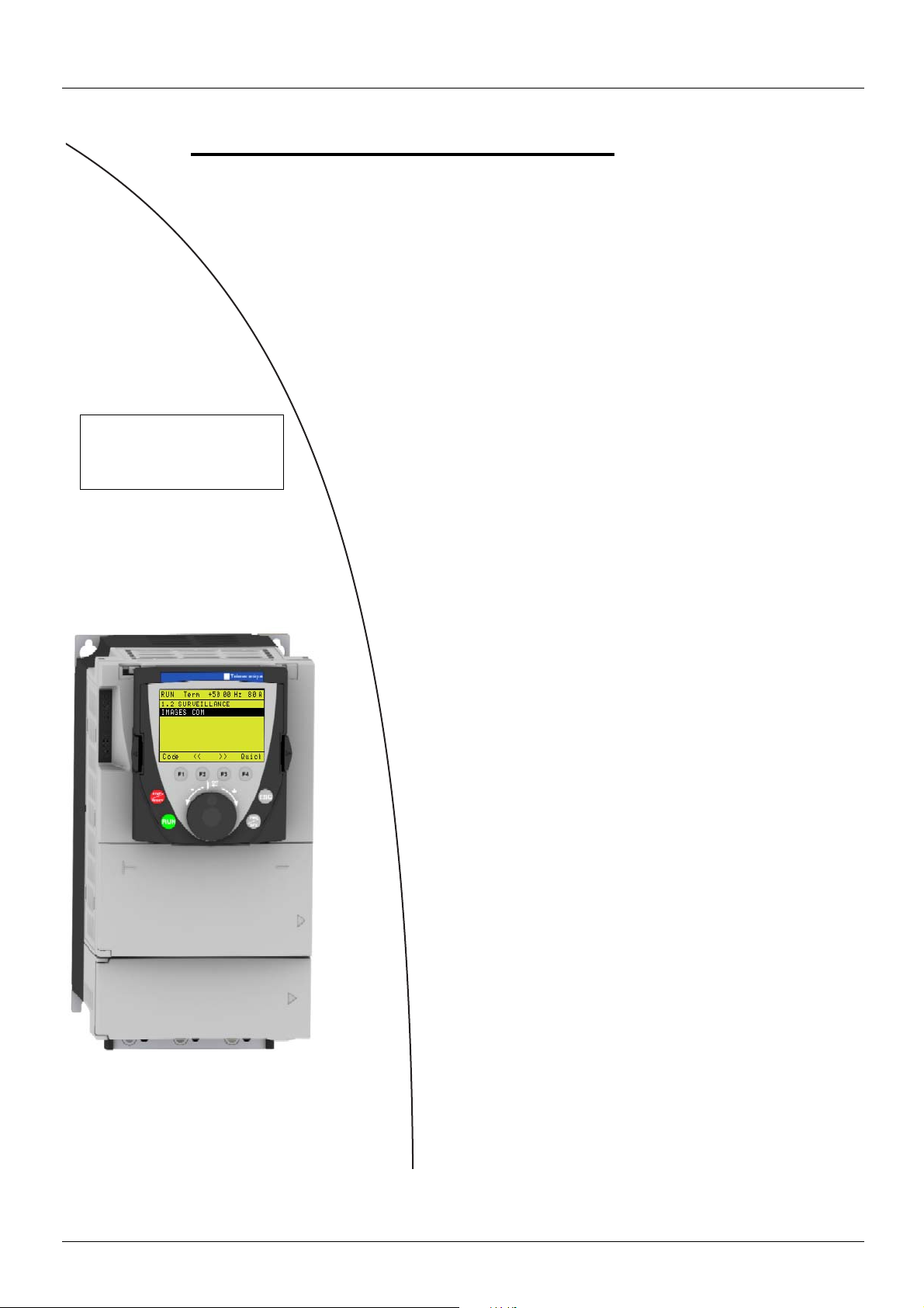
Remote display terminal ________________________________________________________________________________ 26
Power cables _______________________________________________ __________________________________________ 27
Implementation of the Altivar 61 communication option cards __________________________________________________________ 37
General _____________________________________________________________________________________________ 37
Communication via Modbus network _______________________________________________________________________ 39
Communication via Unitelway/Modbus network and VW3 A3 303 option card _______________________________________ 42
Communication via CANopen network _____________________________________________________________________ 43
Communication via Profibus DP network ___________________________________________________________________ 45
Communication via Fipio network - VW3 A3 311 option card ____________________________________________________ 47
Communication via Interbus network _______________________________________________________________________ 49
Communication via Modbus Plus network ___________________________________________________________________ 50
Communication via DeviceNet network _____________________________________________________________________ 52
Communication via Ethernet network ______________________________________________________________________ 61
AS-i ________________________________________________________________________________________________ 70
Application-specific option cards __________________________________________________________________________ 73
3
Page 4
Implementation procedure
Migration from ATV 38 ATV 61
b 1 Identifying the existing ATV 38
Steps 3 and 4 must
be performed with
the power off.
V
v Make an inventory of your Altivar 38 installation.
b 2 Selecting the ATV 61
v Determine the Altivar 61 catalog number.
v Choose the various options required.
b 3 Mounting
v Mount the drive in accordance with the
instructions in this document, using the
substitution kit.
v Install any internal and external options.
b 4 Wiring
v Connect the motor, ensuring that its
connections correspond to the voltage.
v Connect the control.
v Connect the speed reference.
v Connect the line supply, after making sure
that the power is off.
b 5 Configuration
v Drive
v Communication cards
4
Page 5

Altivar 38 hardware identification
Before selecting the Altivar 61, the Altivar 38 hardware configuration needs to be determined carefully.
Measure the line voltage and indicate the type of power supply:
1
Line voltage:_________V Three-phase
ATV38HD16N4
Input V : 380/460V-50/60Hz
Input phase : 3
Note down the drive catalog number, which appears on the Altivar 38 nameplate:
2
ATV38______________________
Note down the catalog number of any EMC filter installed under the drive:
3
Input I : 35.4/28 A
Input fuse : Type J : 60A Max
Cu AWG 6 : 75˚C : 20lb-in/2.26 Nm
LISTED 170M
IND.CONT.EQ
Serial N . 1703001070 France - 6W 0202
VW3A584 ___________________
Note down the catalog number of any option cards installed in the Altivar 38; this can be found on the label attached to the card:
4
Motor Rating : 11 kW / 15HP
Output 3 Ph : 380/460V
Output I : 22A
Output I max. transient (1mn) : 24.2A
Output frequency : 0.1-500Hz
N998
Motor Protective Device
AIC 22000 A Protection type Classe 20
VW3A58_____________________
Note down whether the operator terminal is used:
5
VW3A58101: YES NO
Is the operator terminal connected remotely on the enclosure
door?
Note down the catalog number of the NEMA type 1 mounting kit, if used:
6
VW3A5885___________________
Note down the catalog number of the control card fan kit, if used:
7
VW3A5882___________________
Make sure you have the diagrams for the existing installation.
8
YES NO
5
Page 6

1. Determining catalog numbers
1. 1. Choosing the Altivar 61 catalog number
Required information (refer to page 5): type of use, line voltage, Altivar 38 catalog number
1. 1. 1. Your catalog number starts with ATV38H
Power supply
380…460 V three-phase
ATV38 catalog
number
ATV38HU18N4 0.75 1 ATV 61H075N4 (1) VW3 A9 302
ATV38HU29N4 1.5 2 ATV 61HU15N4 (1) VW3 A9 302
ATV38HU41N4 2.2 3 ATV 61HU22N4 (1) VW3 A9 304
ATV38HU54N4 3.0 - ATV 61HU30N4 (1) VW3 A9 304
ATV38HU72N4 4.0 5 ATV 61HU40N4 (1) VW3 A9 304
ATV38HU90N4 5.5 7.5 ATV 61HU55N4 (1) VW3 A9 305
ATV38HD12N4 7.5 10 ATV 61HU75N4 (1) VW3 A9 306
ATV38HD16N4 11 15 ATV 61HD11N4 (1) VW3 A9 307
ATV38HD23N4 15 20 ATV 61HD15N4 (1) VW3 A9 308
ATV38HD25N4 (X) 18.5 25 ATV 61HD18N4 (2) VW3 A9 309
ATV38HD28N4 (X) 22 30 ATV 61HD22N4 (2) VW3 A9 310
ATV38HD33N4 (X) 30 40 ATV 61HD30N4 (2) VW3 A9 312
ATV38HD46N4 (X) 37 50 ATV 61HD37N4 (2) VW3 A9 312
ATV38HD54N4 (X) 45 60 ATV 61HD45N4 (2) VW3 A9 312
ATV38HD64N4 (X) 55 75 ATV 61HD55N4 (2) VW3 A9 312
ATV38HD79N4 (X) 75 100 ATV 61HD75N4 (2) VW3 A9 312
ATV38HC10N4 (X) 90 125 ATV 61HD90N4 (2)
ATV38HC13N4 (X) 110 150 ATV 61HC11N4 (2)
ATV38HC15N4 (X) 132 200 ATV 61HC13N4 (2)
ATV38HC19N4 (X) 160 250 ATV 61HC16N4 (2)
ATV38HC23N4 (X) 200 300 ATV 61HC22N4 (2)
ATV38HC25N4 (X) 220 350 ATV 61HC22N4 (2)
ATV38HC28N4 (X) 250 400 ATV 61HC25N4 (2)
ATV38HC31N4 (X) 280 450 ATV 61HC31N4 (2)
ATV38HC33N4 (X) 315 500 ATV 61HC31N4 (2)
Power
kW HP
ATV 61 catalog number Substitution kit
Substitution kit: This kit consists of a metal support plate that makes it possible to re-use the same mounting holes as the ATV38.
(1)Drive supplied with a graphic display terminal that can be connected remotely. To order a drive without a graphic display terminal, add
the letter Z at the end of the catalog number. The drive will then be equipped with the integrated 7-segment display terminal.
(2)On ATV38 catalog numbers ending with X, the RFI filter is disconnected in the event of use on an IT system (page 27
implementation).
1. 1. 2. Your catalog number starts with ATV38ED
You must install the Altivar 61 in an enclosure and customize the control devices yourself.
6
Page 7

1. Determining catalog numbers
1. 2. Selecting the power circuit options
1. 2. 1. Radio interference filters (VW3A684x)
The filters previously installed on the ATV38 are not compatible with the ATV 61 and must, therefore, be replaced.
No kit for substitution (mounting) between the 2 filter ranges.
Drive catalog number Filter catalog number
ATV 61H075N4, U15N4, U22N4 VW3 A4 401
ATV 61HU30N4, U40N4 VW3 A4 402
ATV 61HU55N4, U75N4 VW3 A4 403
ATV 61HD11N4 VW3 A4 404
ATV 61HD15N4, D18N4 VW3 A4 405
ATV 61HD22N4 VW3 A4 406
ATV 61HD30N4, D37N4 VW3 A4 407
ATV 61HD45N4, D55N4, D75N4 VW3 A4 408
ATV 61HD90N4, C11N4, C13N4, C16N4 VW3 A4 410
ATV61HC22N4, C25N4, C31N4 VW3 A4 411
1. 2. 2. Line chokes
VZ1L0xxxMxx, VW3A5850x, VW3A6650x, VW3A6850x
The line chokes used with the ATV38 can be re-used with the ATV 61 and do not, therefore, need to be replaced.
1. 2. 3. Output filters (LR filters, LC filters)
VW3A584 5x, VW3A6641x, VW3A6642x
The output filters used with the ATV38 can be re-used with the ATV 61 and do not, therefore, need to be replaced.
1. 2. 4. Motor chokes
VW3A6650x, VW3A6855x
The motor chokes used with the ATV38 can be re-used with the ATV 61 and do not, therefore, need to be replaced.
1. 2. 5. Braking resistors
VW3A5870x, VW3A5873x, VW3A6670x
The braking resistors used with the ATV38 can be re-used with the ATV 61 and do not, therefore, need to be replaced.
7
Page 8

1. Determining catalog numbers
1. 3. Mounting accessories
1. 3. 1. Removable power terminal kit (VW3A5881x)
There is no equivalent to this kit for the Altivar 61.
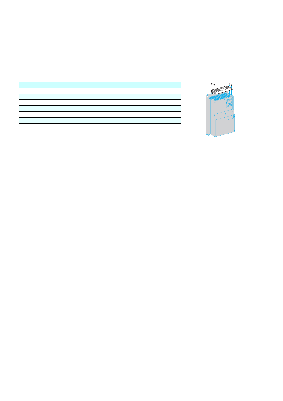
1. 3. 2. Air exchanger kit (VW3A5880x)
There is no equivalent to this kit for the Altivar 61.
Alternative solution: Mount the power part outside the enclosure using the ATV 61 VW3 A9 5xx flange-mounting kit. This solution can be
used to reduce the heat dissipated inside the enclosure.
1. 3. 3. NEMA type 1 mounting kit
Required information: Altivar 61 catalog number
Catalog number selectio n gu ide:
ATV 61 catalog number NEMA kit
ATV 61H075N4 VW3 A9 201
ATV 61HU15N4 VW3 A9 201
ATV 61HU22N4 VW3 A9 201
ATV 61HU30N4 VW3 A9 202
ATV 61HU40N4 VW3 A9 202
ATV 61HU55N4 VW3 A9 203
ATV 61HU75N4 VW3 A9 203
ATV 61HD11N4 VW3 A9 204
ATV 61HD15N4 VW3 A9 205
ATV 61HD18N4 VW3 A9 205
ATV 61HD22N4 VW3 A9 206
ATV 61HD30N4 VW3 A9 207
ATV 61HD37N4 VW3 A9 207
ATV 61HD45N4 VW3 A9 209
ATV 61HD55N4 VW3 A9 209
ATV 61HD75N4 VW3 A9 209
8
Page 9
1. Determining catalog numbers
1. 4. Control circuit options
1. 4. 1. Control card fan kit (VW3A5882x)
Required information: Altivar 61 catalog number
At an ambient temperature between 50°C and 60°C, the Altivar 61 has a higher operati ng capacity than the Altivar 38.
The control card fan kit is required for the following ATV 61 ratings if t he ambient temperature is between 50 and 60°C.
ATV 61 catalog number Control card fan kit
ATV 61HD22N4 VW3 A9 404
ATV 61HD30N4 VW3 A9 405
ATV 61HD37N4 VW3 A9 405
ATV 61HD45N4 VW3 A9 407
ATV 61HD55N4 VW3 A9 407
ATV 61HD75N4 VW3 A9 407
1. 4. 2. Separate control card power supply kit (VW3A5860x)
This kit serves no purpose as the ATV 61 integrates this function as standard and requires the presence of an external 24 V DC (30 W)
supply.
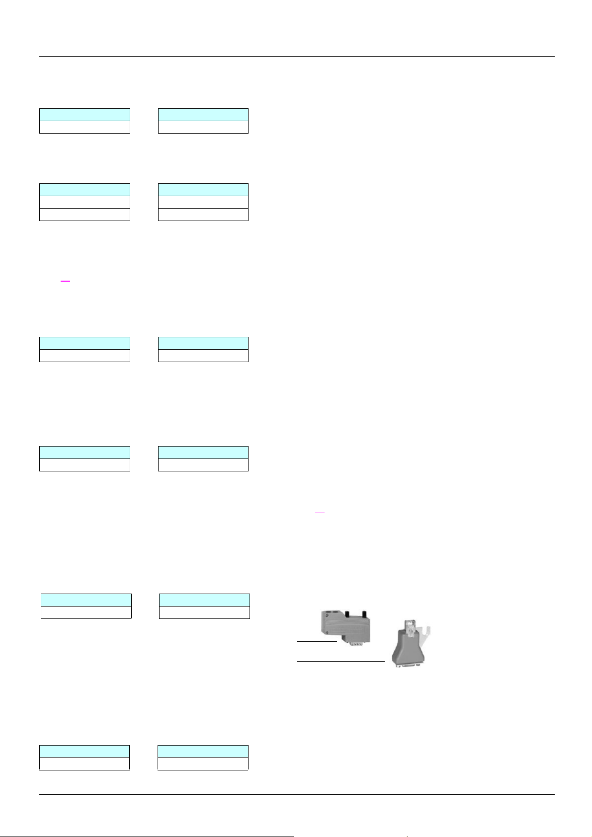
1. 4. 3. Remote display terminal (VW3A58103)
Remote connection of the Altivar 61 graphic display terminal on the enclosure door
IP54 version Remote mounting kit : VW3 A1 102
3-meter cable : VW3 A1 104 R30
IP65 version Remote mounting kit : VW3 A1 102
IP65 door : VW3 A1 103
3-meter cable : VW3 A1 104 R30
RJ45 female/female adapter : VW3 A1 105
This should be used in the above two instances.
Note: Order an Altivar 61 with graphic display terminal (without Z at the end of the catalog number).
Other connection cable lengths are available:
Cable 1 m VW3 A1 104 R10
5 m VW3 A1 104 R50
10 m VW3 A1 104 R100
Note: The graphic display terminal catalog number is VW3 A1 101.
9
Page 10

1. Determining catalog numbers
1. 5. Selecting I/O extension cards (VW3A58201, VW3A58202)
1. 5. 1. ATV38 and I/O option cards (VW3A58201, VW3A58202)
Required information: Connection diagram, presence of an I/O extension card
As standard the ATV 61 has more I/O than the ATV38.
• If the ATV38 is not equipped with an I/O extension card, there is no need to add a card to the Altivar 61. Ignore this section.
• If the ATV38 is equipped with an I/O extension card, it is important to know which inp uts/outputs are used as wel l as the function assigned
to AI3 (VW3A58201 card) and to encoder input A, A
The tables below can be used to ascertain what was used previously and, therefore, to find the equivalent on ATV 61 with or without an
option card.
Scenario 1: Replacing an ATV38 with or without a VW3A58201 option card:
Used: Becomes:
ATV38 ATV 61 Description VW3A58201 VW3 A3 201 VW3 A3 202 Description
R1A/R1B/
R1C
R2A/R2C R2A/R2C Programmable relay (R2)
AO 1 AO 1 0-20 mA analog output -10 -10 -10 -10 V output
COM COM Analog input common TH1+ TH2+ PTC probe
AI 1 AI 1+ 0…10 V analog input TH1- TH2- PTC probe
+10 +10
AI 2 AI 2
LI 1 LI 1
LI 2 LI 2
LI 3 LI 3
LI 4 LI 4
+24 +24 Logic input power supply LO 2 LO 4 Logic output
R1A/R1B/
R1C
LI 5
LI 6
Fault relay (R1) COM 0 V 0 V Common
1 to 10 kΩ potentiometer
power supply
Analog input
0…10 V 0..4/20 mA
24 V DC run forward logic
inputs
24 V DC programmable
logic input
24 V DC programmable
logic input
24 V DC programmable
logic input
24 V DC programmable
logic input
24 V DC programmable
logic input
, B, B (VW3A58201 card).
+24 +24 +24 Logic input power supply
LI 5 also on
control card
LI 6 also on
control card
LO LO 1 LO 3 Logi c output
LO + CLO CLO Logic output power supply
AI 3A/AI3 B
g
AO AO 2
+10 +10 V output
R3A/R3B/
R3C
LI 7 LI 11
LI 8 LI 12
LI 9 LI 13
LI10 LI 14
AI3 +/AI3 -
R4A/R4B/
R4C
Current
AI4 Programmable analog input
AO 3
FP Pulse input
Programmable relay
24 V DC programmable
logic input
24 V DC programmable
logic input
24 V DC programmable
logic input
24 V DC programmable
logic input
Programmable analog input
Programmable analog
output
Programmable analog
output
g Review of the various instances of use of the AI3 input on the VW3A58201 card:
AI3 assignment
PTC Use LI6 on ATV 61 control card in PTC mode and adjust SW2 (see page xx
Use the TH inputs on the VW3 A3 201 or VW3 A3 202 option cards (see page xx
Speed reference Two different options
ATV38 ATV 61
AI3 (0..10 V) AI1 or AI2 if available
AI3 (+/- 10 V) AI1
10
)
)
Page 11
1. Determining catalog numbers
PI feedback or summed reference: Three different options
ATV38 ATV 61
AI3 (0..10 V) AI1 or AI2 if available
AI4 on VW3 A3 202 option card
AI3 (+/- 10 V) AI1
Tachometer: Totally incompatible. Alternative solution: use an incremental encoder.
Scenario 2: Replacing an ATV38 with or without a VW3A58202 option card:
Used: Becomes:
ATV38 ATV 61 Description VW3A58202
R1A/R1B/
R1C
R2A/R2C R2A/R2C
AO 1 AO 1
COM COM Analog input common TH1+ TH2+ PTC probe
AI 1 AI 1+ 0…10 V analog input TH1- TH2- PTC probe
+10 +10
AI 2 AI 2
LI 1 LI 1
LI 2 LI 2
LI 3 LI 3
LI 4 LI 4
+24 +24
R1A/R1B/
R1C
LI 5
LI 6
Fault relay (R1) COM 0 V 0 V Common
Programmable relay
(R2)
0-20 mA
analog output
1 to 10 kΩ
potentiometer power
supply
0…10 V 0..4/20 mA
analog input
24 V DC run forward
logic inputs
24 V DC programmable
logic input
24 V DC programmable
logic input
24 V DC programmable
logic input
Logic input power
supply
24 V DC programmable
logic input
24 V DC programmable
logic input
-10 -10 -10 -10 V output
+24 +24 +24
LI 5 also on
control card
LI 6 also on
control card
LO LO 1 LO 3 Logic output
LO + CLO CLO
AO AO 2
A3 201 A3 202 A3 407
R3A/R3B/
R3C
LI 7 LI 11
LI 8 LI 12
LI 9 LI 13
LI 10 LI 14
LO 2 LO 4 Logic output
VW3... card
R4A/R4B/
R4C
Current
AI3 +/AI3 -
AI4
AO 3
FP Pulse input
Description
Programmable relay
Logic input power
programmable logic
24 V DC programmable
programmable logic
programmable logic
Logic output power
Programmable analog
Programmable analog
Programmable analog
Programmable analog
24 V DC
logic input
24 V DC
24 V DC
supply
input
input
input
supply
input
input
output
output
A A
A- A-
B B
B- B-
Examples:
- If only LI5 and LI6 are used on the VW3A58202 card
ª An option card is not needed with the ATV 61 because Li5 and Li6 are features of the standard product.
- If only the incremental encoder inputs are used on the VW3A58202 card
ª Use the VW3 A3 407 encoder card.
Incremental encoder
input
Incremental encoder
input
Incremental encoder
input
Incremental encoder
input
0 V Encoder 0 V
PES Encoder 5 V
11
Page 12
1. Determining catalog numbers
1. 6. Selecting communication channels
1. 6. 1. Communication via Modbus network
With this type of communication, there are several possible scenarios:
1) The Altivar 38 was connected via the connector port using the RS485 connection kit (VW3A58306): The connection cable should be
replaced because the ATV61 has an RJ45 type Modbus port, but the port on the ATV38 is a 9-way SUB-D.
ATV38 connected to Catalog number Description
TSXSCA50 junction box or other screw terminals VW3 A8 306 D30 Length 3 m, an RJ45 connector at one end and stripped at the
TSXSCA62 subscriber socket VW3 A8 306 Length 3 m, an RJ45 connector at one end and a 15-way
other
SUB-D connector at the other
The integrated Modbus port does not have any pulldown resistors, but d epending on the type of subscriber and the master modul e
present on the bus, it may be necessary to match these pulldown resistors (see page 39
2) The Altivar 38 was connected via the VW3A58303 card to a Unitelway or 4-wire Modbus RTU/Jbus/ASCII network.
The Altivar 61’s integrated Modbus port does not support these network services and it is, therefore, necessary to use an option card.
Card catalog number
ATV38 ATV 61
VW3A58303 VW3 A3 303
In this example, keep the existing connections.
If the VW3A58303 card was used with the 2-wire Modbus RTU protocol, connec tion on t he Alti var 61’s RJ45 port is pos sible, as
this is compatible with the presence of the graphic displa y terminal . Only the di agnosti c service (08) is restri cted to subcodes 00,
0A, 0C, 0E. Use the connection method described in Point 1.
).
1. 6. 2. Communication with Profibus bus (VW3A58307)
Card catalog number
ATV38 ATV 61
VW3A58307 VW3 A3 307
Installation and connection
For the Altivar 61, keep the existing connections.
1. 6. 3. Communication with DeviceNet bus (VW3A58309)
Card catalog number
ATV38 ATV 61
VW3A58309 VW3 A3 309
Installation and connection
For the Altivar 61, keep the existing connections.
1. 6. 4. Communication via Modbus Plus bus (VW3A58302)
Card catalog number
ATV38 ATV 61
VW3A58302 VW3 A3 302
Installation and connection
For the Altivar 61, keep the existing connections.
12
Page 13
1. Determining catalog numbers
1. 6. 5. Communication with Metasys N2 bus VW3A58354U
Card catalog number
ATV38 ATV 61
VW3A58354U VW3 A3 313
1. 6. 6. Communication with INTERBUS bus (VW3A58304(E))
Card catalog number
ATV38 ATV 61
VW3A58304 VW3 A3 304
VW3A58304E VW3 A3 304
Installation and connection
For the Altivar 61, keep the existing connections.
It is essential to use the Altivar 61 control card’s external power supply function so that the bus token can circulate continuously (see
page 26
).
1. 6. 7. Communication via Ethernet network (VW3A58310)
Card catalog number
ATV38 ATV 61
VW3A58310 VW3 A3 310
Installation and connection
For the Altivar 61, keep the existing connections.
1. 6. 8. Communication via Fipio bus VW3A58311
Card catalog number
ATV38 ATV 61
VW3A58311 VW3 A3 311
Installation and connection
If a TSX FP ACC12 connector is used to link the Altivar to the bus, keep the existing connections. However, it is necessary to alter the
position of the cable(s) when using a TSX FP ACC2 connector (see page 47
).
1. 6. 9. Communication via CANopen bus (VW3A58308)
Card catalog number
The Altivar 61 integrates the ATV38 CANopen communication card’s connection and services as standard (VW3A58308).
It is however necessary to modify the wiring.
ATV38 ATV 61
Screw terminals 9-way Sub-D
To adapt the wiring, order:
- 9-way Sub-D connector (1 per drive): VW3 CAN KCDF 180T
- 9-way Sub-D/RJ45 adapter (1 per drive): VW3 CAN A71
1. 6. 10. Communication via AS-i bus (VW3A58305)
Card catalog number
Although the AS-i communication card has not been continued in the Altivar 61 offer, there is a solution for substitution using a 4-input/
4-output module on the AS-i bus.
ATV38 ATV 61
VW3A58305 ASI 20M T4I4OS
13
Page 14

2. Drive implementation
2. 1. Installation
2. 1. 1. Using catalog numbers starting with ATV38H
The dimensions given in the following sections can be used to compare those of an Al tivar 38 equipped with an optio n card and its operator
terminal with an Altivar 61 also equipped with an opti on card and operator terminal.
These tables only include examples where the Altivar 61 takes up more space than the Altivar 38, as well as the proposed solutions.
14
Page 15

2. Drive implementation
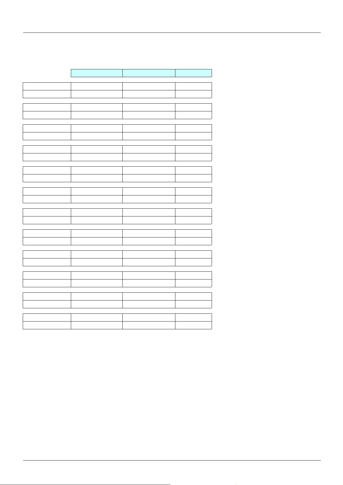
2. 1. 1. 1. Three-phase supply 380…480 V (for catalog numbers starting with ATV38H)
Comparison of dimensions
Width (1) Height (2) Depth (3)
ATV38HU18N4 150 226 184
ATV 61H075N4 130 230 195
ATV38HU29N4 150 226 184
ATV 61HU15N4 130 230 195
ATV38HU41N4 150 226 184
ATV 61HU22N4 130 230 195
ATV38HU54N4 175 285 184
ATV 61HU22N4 155 260 207
ATV38HU72N4 175 285 184
ATV 61HU40N4 155 260 207
ATV38HU90N4 175 285 184
ATV 61HU55N4 175 295 207
ATV38HD12N4 230 325 210
ATV 61HU75N4 175 295 187
ATV38HD16N4 230 325 210
ATV 61HD11N4 210 295 213
ATV38HD23N4 230 415 210
ATV 61HD15N4 230 400 213
ATV38HD28N4 (X) 240 550 283
ATV 61HD15N4 230 400 213
ATV38HD25N4 (X) 240 550 283
ATV 61HD18N4 230 400 213
ATV38HD33N4 (X) 240 550 283
ATV 61HD30N4 240 550 266
ATV38HD46N4 (X) 240 550 283
ATV 61HD37N4 240 550 266
(1) No problem if space is left between 2 drives. Width incompatible if the ATV38 drives are mounted side by side.
(2) This difference is easily made up by the space required for the drive wiring.
(3) The depth of enclosures is usually considerably greater than that of the products.
If the enclosure depth poses a problem, it is alwa ys possible to order an Alt ivar 61 wit h a Z at the end of th e catalog numbe r. Your drive wi ll
be supplied without a graphic display terminal and will, therefore , be 23 mm slimmer, e.g., ATV 61H075N4Z.
15
Page 16
2. Drive implementation
2. 1. 1. 2. Three-phase supply 380…480 V for catalog numbers starting with ATV38H.
Comparison of dimensions
Width (1) Height (2) Depth (3)
ATV38HD54N4 (X) 350 650 304
ATV 61HD45N4 320 630 290
ATV38H64N4(X) 350 650 304
ATV 61HD55N4 320 630 290
ATV38HD79N4 (X) 350 650 304
ATV 61HD75N4 320 630 290
ATV38HC10N4 (X) 370 630 360
ATV 61HD90N4 320 920 377
ATV38HC13N4 (X) 480 680 400
ATV 61HC11N4 320 920 377
ATV38HC15N4 (X) 480 680 400
ATV 61HC13N4 360 1022 377
ATV38HC19N4 (X) 480 680 400
ATV 61HC16N4 340 1190 377
ATV38HC23N4 (X) 660 950 440
ATV 61HC22N4 440 1190 377
ATV38HC25N4 (X) 660 950 440
ATV 61HC22N4 440 1190 377
ATV38HC28N4 (X) 660 950 440
ATV 61HC25N4 440 1190 377
ATV38HC31N4 (X) 660 950 440
ATV 61HC31N4 440 1190 377
ATV38HC33N4 (X) 660 950 440
ATV 61HC31N4 440 1190 377
(1) No problem if space is left between 2 drives. Width incompatible if the ATV38 drives are mounted side by side.
(2) This difference is easily made up by the space required for the drive wiring.
(3) The depth of enclosures is usually considerably greater than that of the products.
If the enclosure depth poses a problem, it is alwa ys possible to order an Alt ivar 61 wit h a Z at the end of th e catalog numbe r. Your drive wi ll
be supplied without a graphic display terminal and will, therefore , be 23 mm slimmer, e.g., ATV 61H075N4Z.
16
Page 17
2. Drive implementation
2. 2. Comparison of dimensions
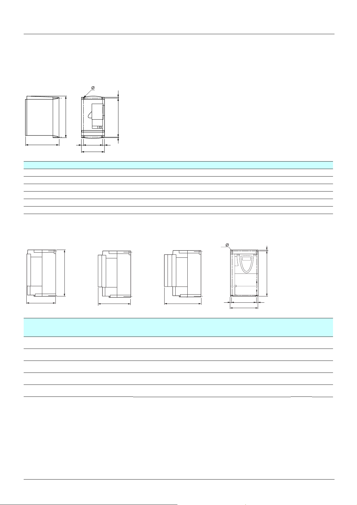
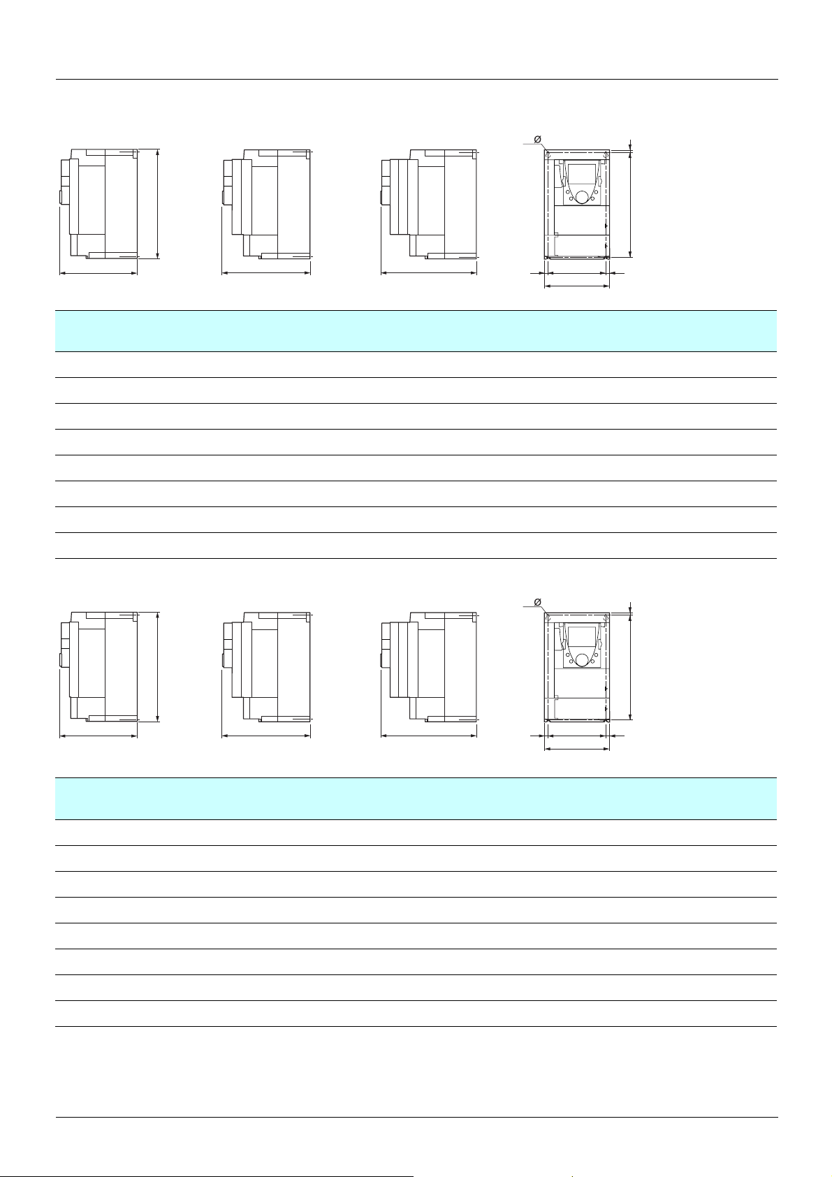
2. 2. 1. Dimensions
ATV38Hppp product on heatsink
=
b
=c
G=
a
=H
ATV-38H a b c G H Ø
U18N4, U29N4, U41N4 150 230 184 133 210 5
U54N4, U72N4, U90N4 175 286 184 155 270 5.5
D12N4, D16N4 230 325 210 200 310 5.5
D23N4 230 415 210 200 400 5.5
D25N4p, D28N4p, D33N4p, D46N4p 240 550 283 205 530 7
D54N4p, D64N4p, D79N4p 350 650 304 300 619 9
ATV 61H
No option card
ppp y 15 kW without graphic display terminal, with and without option cards
With 1 option card
b
c
c1
With 2 option cards
c2
4 x
=
G
a
h
H
=
ATV 61H a
mm
(in.)
075N4, U15N4,U22N4
U30N4, U40N4
U55N4, U75N4
D11N4
D15N4
130
(5.12)
155
(6.10)
175
(6.89)
210
(8.27)
230
(9.05)
b
mm
(in.)
230
(9.05)
260
(10.23)
295
(11.61)
295
(11.61)
400
(15.75)
c
mm
(in.)
149
(5.87)
161
(6.34)
161
(6.34)
187
(7.36)
187
(7.36)
c1
mm
(in.)
172
(6.77)
184
(7.25)
184
(7.25)
210
(8.27)
210
(8.27)
c2
mm
(in.)
195
(7.68)
207
(8.15)
207
(8.15)
233
(9.17)
233
(9.17)
G
mm
(in.)
113.5
(4.47)
138
(5.43)
158
(6.22)
190
(7.48)
210
(8.26)
H
mm
(in.)
220
(8.66)5(0.20)5(0.20)
249
(9.80)4(0.16)5(0.20)
283
(11.14)6(0.24)6(0.24)
283
(11.14)6(0.24)6(0.24)
386
(15.20)8(0.31)6(0.24)
h
mm
(in.)
Ø
mm
(in.)
For
screws
M4 3
M4 4
M5 5.5
M5 7
M6 9
Weight
kg
(lb.)
(6.61)
(8.82)
(12.13)
(15.43)
(19.84)
17
Page 18
2. Drive implementation
ATV 61Hppp y 15 kW with graphic display terminal, with and without option cards
No option card
With 1 option card (1)
With 2 option cards (1)
4 x
h
b
c
ATV 61H a
075N4, U15N4,U22N4
U30N4, U40N4
U55N4, U75N4
D11N4
D15N4, D18N4
D22N4
D30N4, D37N4
D45N4, D55N4, D75N4
ATV 61H
No option card
ppp y 75 kW with graphic display terminal, with and without option cards
(5.12)
(6.10)
(6.89)
(8.27)
(9.05)
(9.45)
(9.45)
(12.60)
With 1 option card (1)
mm
(in.)
130
155
175
210
230
240
240
320
H
c1
b
mm
(in.)
230
(9.05)
260
(10.23)
295
(11.61)
295
(11.61)
400
(15.75)
420
(16.54)
550
(21.65)
630
(24.80)
c
mm
(in.)
172
(6.77)
184
(7.25)
184
(7.25)
210
(8.27)
210
(8.27)
210
(8.27)
240
(9.45)
290
(11.42)
With 2 option cards (1)
c2
c1
mm
(in.)
195
(7.68)
207
(8.15)
207
(8.15)
233
(9.17)
233
(9.17)
243
(9.57)
263
(10.35)
315
(12.40)
c2
mm
(in.)
218
(8.58)
230
(9.06)
230
(9.06)
256
(10.08)
256
(10.08)
266
(10.47)
286
(11.25)
335
(13.19)
G
==
G
mm
(in.)
113.5
(4.47)
138
(5.43)
158
(6.22)
190
(7.48)
210
(8.26)
206
(8.11)
206
(8.11)
280
(11.02)
4 x
a
H
mm
(in.)
220
(8.66)5(0.20)5(0.20)
249
(9.80)4(0.16)5(0.20)
283
(11.14)6(0.24)6(0.24)
283
(11.14)6(0.24)6(0.24)
386
(15.20)8(0.31)6(0.24)
403
(15.87)11(0.45)
531.5
(20.93)11(0.45)
604.5
(23.80)15(0.59)9(0.22)
h
mm
(in.)
h
Ø
mm
(in.)
5.5
(0.22)
5.5
(0.22)
For
screw
s
M4 3
M4 4
M5 5.5
M5 7
M6 9
M6 30
M6 37
M8 45
Weight
kg
(lb.)
(6.61)
(8.82)
(12.13)
(15.43)
(19.84)
(66.14)
(81.57)
(99.21)
b
c
ATV 61H a
mm
(in.)
075N4, U15N4,U22N4
U30N4, U40N4
U55N4, U75N4
D11N4
D15N4, D18N4
D22N4
D30N4, D37N4
D45N4, D55N4, D75N4
130
(5.12)
155
(6.10)
175
(6.89)
210
(8.27)
230
(9.05)
240
(9.45)
240
(9.45)
320
(12.60)
H
c1
b
mm
(in.)
230
(9.05)
260
(10.23)
295
(11.61)
295
(11.61)
400
(15.75)
420
(16.54)
550
(21.65)
630
(24.80)
c
mm
(in.)
172
(6.77)
184
(7.25)
184
(7.25)
210
(8.27)
210
(8.27)
210
(8.27)
240
(9.45)
290
(11.42)
c2
c1
mm
(in.)
195
(7.68)
207
(8.15)
207
(8.15)
233
(9.17)
233
(9.17)
243
(9.57)
263
(10.35)
315
(12.40)
c2
mm
(in.)
218
(8.58)
230
(9.06)
230
(9.06)
256
(10.08)
256
(10.08)
266
(10.47)
286
(11.25)
335
(13.19)
G
==
G
mm
(in.)
113.5
(4.47)
138
(5.43)
158
(6.22)
190
(7.48)
210
(8.26)
206
(8.11)
206
(8.11)
280
(11.02)
a
H
mm
(in.)
220
(8.66)5(0.20)5(0.20)
249
(9.80)4(0.16)5(0.20)
283
(11.14)6(0.24)6(0.24)
283
(11.14)6(0.24)6(0.24)
386
(15.20)8(0.31)6(0.24)
403
(15.87)11(0.45)
531.5
(20.93)11(0.45)
604.5
(23.80)15(0.59)9(0.22)
h
mm
(in.)
Ø
mm
(in.)
5.5
(0.22)
5.5
(0.22)
For
screw
s
M4 3
M4 4
M5 5.5
M5 7
M6 9
M6 30
M6 37
M8 45
Weight
kg
(lb.)
(6.61)
(8.82)
(12.13)
(15.43)
(19.84)
(66.14)
(81.57)
(99.21)
18
Page 19
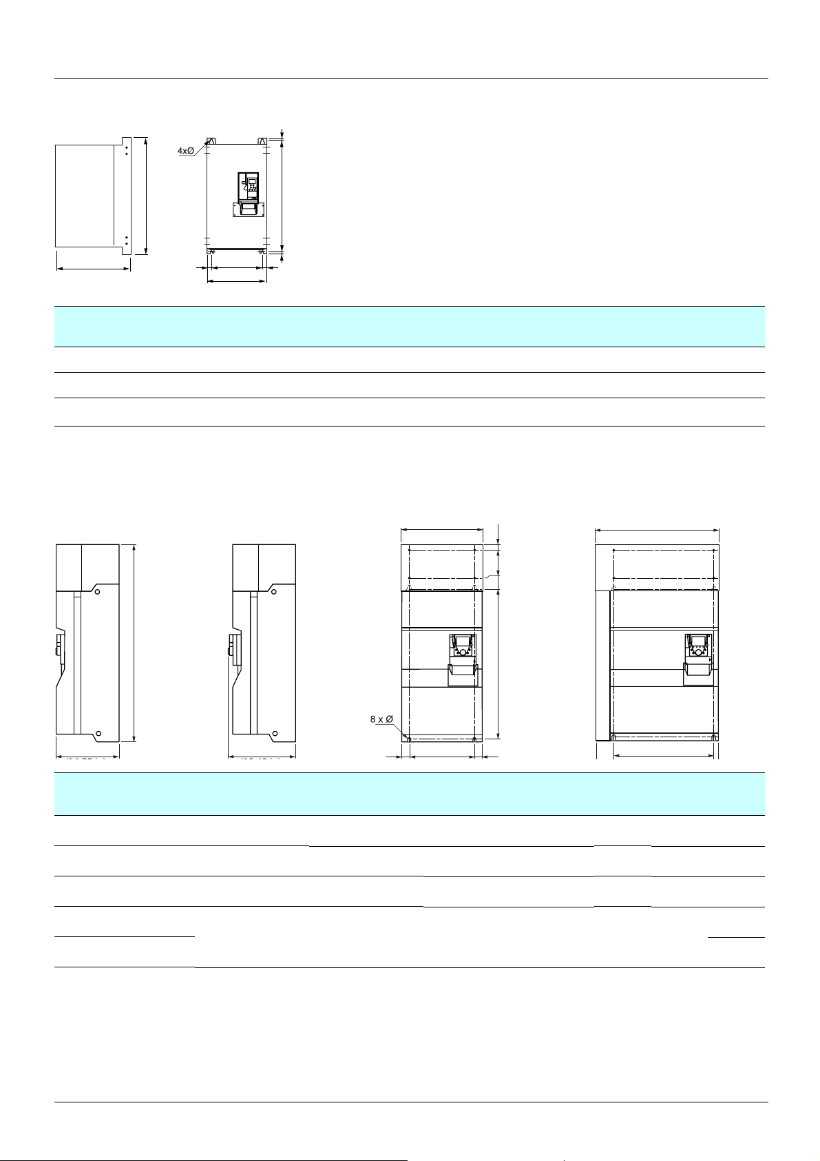
2. Drive implementation
=
ATV 38Hppp > 75 kW and y 315 kW - Product on heatsink
b
G
c
==
a
ATV 61H a
C10N4X
C13N4X, C15N4X, C19N4X
C23N4X, C25N4X, C28N4X,
C31N4X, C33N4X
ATV 61H
ppp > 75 kW and y 315 kW with graphic display terminal, with and without option cards
With 2 option cards (1)With 0 or 1 option card (1) ATV61H C25N4 to C31N4 with braking unit
(14.57)
(18.90)
(25.98)
H=
mm
(in.)
370
480
660
b
mm
(in.)
630
(24.80)
680
(26.77)
950
(37.40)
ATV61H D55M3X to D90M3X
ATV61H D90N4 to C31N4
(14.17)
(15.75)
(17.32)
a
c
mm
(in.)
360
400
440
G
mm
(in.)
317.5
(12.50)
426
(16.77)
598
(23.54)
H
mm
(in.)
609
(23.98)
652
(25.67)
920
(36.22)
670 (26.37)
Ø
mm
(in.)
12
(0.47)
12
(0.47)
15
(0.59)
b
HK1KK2
540 mm (21.26 in)
Ø
mm
(in.)
11.5
(0.45)
11.5
(0.45)
11.5
(0.45)
11.5
(0.45)
For
Weight
screws
M10 80
M10 110
M10 140
M10
kg
(lb.)
(176)
(242)
(309)
140
(309)
mm
(in.)
(14.17)
(13.39)
(17.32)
392 mm
(40.23)
(46.62)
(46.62)
b
mm
(in.)
1022
1190
1190
G
mm
(in.)
298
(11.73)
285
(11.22)
350
(13.78)
==G
H
mm
(in.)
758
(29.84)
920
(36.22)
920
(36.22)
K
mm
(in.)
K1
mm
(in.)
K2
mm
(in.)
150
(5.91)72(2.83)30(1.18)
150
(5.91)75(2.95)30(1.18)
150
(5.91)75(2.95)30(1.18)
377 mm
ATV61H a
C13N4 360
C16N4 340
C22N4 440
C25N4
595
C31N4 215
(23.43)
1190
(46.62)
540
(21.26)
920
(36.22)
150
(5.91)75(2.95)30(1.18)
(474)
19
Page 20

2. Drive implementation
2. 3. Mounting the RFI filter
The dimensions given in the following sections can be used to compare the dimensions of the Altivar 38 RFI filters with those used on the
Altivar 61.
These tables only include examples where the Altivar 61 filters take up more space than those fitted on the Altivar 38, as well as the
proposed solutions.
It is important to remember that, without ex ception, it will be necessary to adapt the mounting as the mounting di mensions are not the same.
2. 3. 0. 1. Three-phase supply 400 V for catalog numbers starting with ATV38H
Drive Filter
ATV38HU18N4 VW3A58402 150 276 60 133 260
ATV 61H075N4 VW3 A4 401 130 290 40 105 260
ATV38HU29N4 VW3A58402 150 276 60 133 260
ATV 61HU15N4 VW3 A4 401 130 290 40 105 260
ATV38HU41N4 VW3A58402 150 276 60 133 260
ATV 61HU22N4 VW3 A4 401 130 290 40 105 260
ATV38HU90N4 VW3A58403 175 340 60 153 320
ATV 61HU55N4 VW3 A4 403 175 370 60 150 355
ATV38HD23N4 VW3A58405 230 480 60 200 460
ATV 61HD15N4 VW3 A4 405 230 498.5 62 190 460
ATV38HD54N4 (X) VW3A58408 350 770 110 300 770
ATV 61HD45N4 VW3 A4 408 320 750 119 280 725
ATV38HD64N4 (X) VW3A58408 350 770 110 300 770
ATV 61HD45N4 VW3 A4 408 320 750 119 280 725
ATV38HD79N4 (X) VW3A58408 350 770 110 300 770
ATV 61HD55N4 VW3 A4 408 320 750 119 280 725
ATV38HC10N4 (X) VW3A68401 204 243 88 90 80
ATV 61HD90N4 VW3 A4 410 800 261 139 120 235
Width Height Depth Mounting
a b c G H
ATV38HC13N4 (X) VW3A68402 204 295 89 90 90
ATV 61HC11N4 VW3 A4 410 800 261 139 120 235
ATV38HC15N4 (X) VW3A68402 204 295 89 90 90
ATV 61HC13N4 VW3 A4 410 800 261 139 120 235
ATV38HC19N4 (X) VW3A68402 204 295 89 90 90
ATV 61HC16N4 VW3 A4 410 800 261 139 120 235
ATV38HC23N4 (X) VW3A68403 224 295 89 90 90
ATV 61HC22N4 VW3 A4 411 800 261 139 120 235
ATV38HC25N4 (X) VW3A68403 224 295 89 90 90
ATV 61HC22N4 VW3 A4 411 800 261 139 120 235
ATV38HC28N4 (X) VW3A68403 224 295 89 90 90
ATV 61HC25N4 VW3 A4 411 800 261 139 120 235
ATV38HC31N4 (X) VW3A68403 224 295 89 90 90
ATV 61HC31N4 VW3 A4 411 800 261 139 120 235
ATV38HC33N4 (X) VW3A68403 224 295 89 90 90
ATV 61HC31N4 VW3 A4 411 800 261 139 120 235
20
Page 21

2. Drive implementation
2. 3. 0. 2. Three-phase supply 400…460 V for catalog numbers starting with ATV38H
Drive Filter
ATV38HC10N4 (X) VW3A68415 260 386 115 235 240
ATV 61HD90N4 VW3 A4 410 800 261 139 120 235
ATV38HC13N4 (X) VW3A68435 260 386 115 235 240
ATV 61HC11N4 VW3 A4 410 800 261 139 120 235
ATV38HC15N4 (X) VW3A68435 260 386 115 235 240
ATV 61HC13N4 VW3 A4 410 800 261 139 120 235
ATV38HC19N4 (X) VW3A68435 260 386 115 235 240
ATV 61HC16N4 VW3 A4 410 800 261 139 120 235
ATV38HC23N4 (X) VW3A68465 260 386 135 235 240
ATV 61HC22N4 VW3 A4 411 800 261 139 120 235
ATV38HC25N4 (X) VW3A68465 260 386 135 235 240
ATV 61HC22N4 VW3 A4 411 800 261 139 120 235
ATV38HC28N4 (X) VW3A68465 260 386 135 235 240
ATV 61HC25N4 VW3 A4 411 800 261 139 120 235
Width Height Depth Mounting
a b c G H
ATV38HC31N4 (X) VW3A68465 260 386 135 235 240
ATV 61HC31N4 VW3 A4 411 800 261 139 120 235
ATV38HC33N4 (X) VW3A68465 260 386 135 235 240
ATV 61HC31N4 VW3 A4 411 800 261 139 120 235
21
Page 22
2. Drive implementation
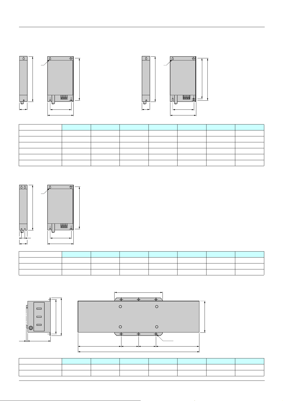
2. 3. 1. Comparison of dimensions
2. 3. 1. 1. RFI filters
Ø
b
c
G
a
H
c
Ø
b
G
a
H1
H
VW3 a (mm) b (mm) c (mm) G (mm) H (mm) H1 (mm) Ø (mm)
A4 401 130 290 40 105 275 – 4.5
A4 402 155 324 50 130 309 – 4.5
A4 403 175 370 60 150 355 – 5.5
A4 404 210 380 60 190 365 – 5.5
A4 405 230 498.5 62 190 479.5 460 6.6
A4 409 230 498.5 62 190 479.5 460 6.6
Ø
H
a (mm) b (mm) c (mm) G (mm) H (mm) J (mm) Ø (mm)
c
VW3
b
GJ
a
A4 406 240 522 79 200 502.5 40 6.6
A4 407 240 650 79 200 631 40 6.6
A4 408 320 750 119 280 725 80 9
a1
b
H
c10
GG==
a
6xØ12
b1
VW3
a (mm) a1 (mm) b (mm) b1 (mm) c (mm) G (mm) H (mm)
A4 410 800 302 261 219 139 120 235
A4 411 800 302 261 219 139 120 235
22
Page 23
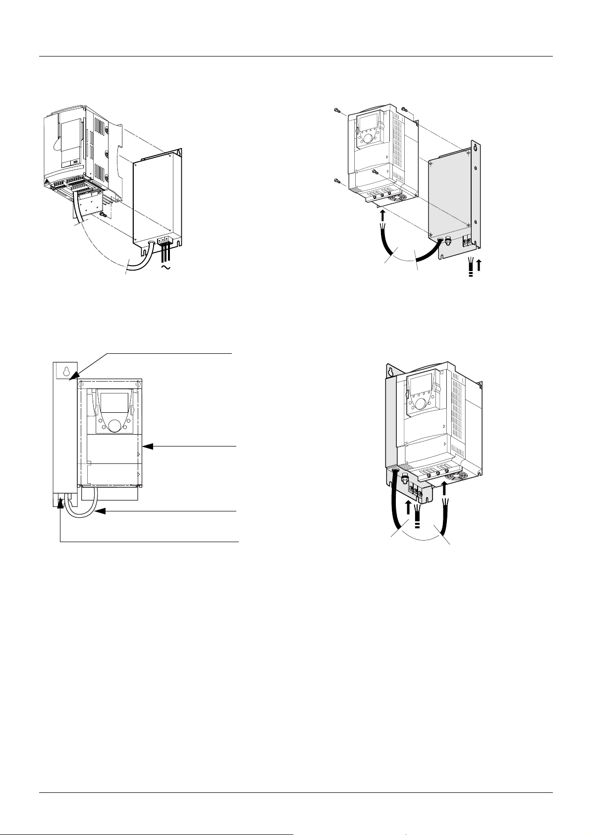
2. Drive implementation
Mounting under the drive
4 x
ATV 38
Side mounting against the ATV 61
ATV 61
Filter
Drive
Filter - Drive connection
Power connection
23
Page 24

2. Drive implementation
2. 4. NEMA mounting kits
Dimensions, in inches and (mm)
a
=
G=
=
c
bd
Kit
Kit catalog
number
=H
Product
size
Kit
Drive catalog number
ATV38Hppppp
a
(in.)b(in.)c(in.)G(in.)H(in.)Ø(in.)d(lb.)
VW3A58852 2 U18N4, U29N4, U41N4 5.91
(150)
VW3A58853 3 U54N4, U72N4, U90N4 6.89
(175)
VW3A58854 4 D12N4, D16N4 9.06
(230)
VW3A58855 5 D23N4 9.06
(203)
C
9.06
(230)
11.26
(286)
12.80
(325)
16.35
(415)
7.24
(184)
7.24
(184)
8.27
(210)
8.27
(201)
5.20
(133)
6.10
(155)
7.9
(200)
7.9
(200)
8.27
(210)
10.63
(270)
12.20
(310)
15.75
(400)
0.20
(5)
0.22
(5.5)
0.22
(5.5)
0.22
(5.5)
2.81
(71)
2.94
(75)
2.94
(75)
2.94
(75)
Kit Kit
Kit catalog
number
Product
size
Drive catalog number
ATV38Hppppp
VW3A58856 6 D25N4, D28N4, D33N4,
D46N4
VW3A58857 7 D54N4, D64N4, D79N4 13.78
24
A
(in.)B(in.)C(in.)E(in.)F(in.)G(in.)I(in.)K(in.)Ø(in.)L(lb.)
9.45
21.65
(240)
25.59
(350)
(550)
(650)
11.14
(283)
11.97
(304)
5.57
(146)
9.29
(236)
12.05
(306)
15.35
(390)
8.07
(205)
11.81
(300)
20.87
(530)
24.37
(619)
0.39
(10)
0.39
(10)
0.28
(7)
0.36
(9)
3.5
(89)
6.75
(171)
Page 25

2. Drive implementation
VW3 A9 101…105, 201…205 VW3 A9 106…108, 206…208
VW3 A9 109…116, VW3 A9 209
Kit for UL NEMA Type 1 conformity or IP 21 protection
VW3 A9 ppp
Drive
Δb
VW3 A9 xxxxx kit
c
b
a
b
a
VW3 a (in.) b (in.) VW3 a (in.) b (in.)
A9 101, 201 130 (5.12) 113 (4.45) A9 106, 206 240 (9.45) 185 (7.28)
A9 102, 202 155 (6.10) 103 (4.06) A9 107, 207 240 (9.45) 180 (7.09)
A9 103, 203 175 (6.89) 113 (4.45) A9 108, 208 32 0 (1 2. 6 0) 178 (7.01)
A9 104, 204 210 (8.27) 113 (4.45)
A9 105, 205 230 (9.06) 108 (4.25)
4xØ
b
c
G
==
a
K2
K
K1
VW3 a (in.) b (in.) c (in.) G (in.) K (in.) K1 (in.) K2 (in.) Ø (in.)
A9 109, 209 320 (12.60) 220 (8.66) 377 (14.84) 250 (9.84) 95 (3.74) 65 (2.56) 75 (2.95) 11.5 (0.45)
25
Page 26

2. Drive implementation
2. 5. Separate control card power supply
A1
ATV61Hppppp
P240V
0 V
+24 V
2. 6. Remote display terminal
Used to connect the programming terminal remotely on the fron t of the enclosure.
Fixings:
As the dimensions are not the same, the fixing holes must be modified.
ATV38 ATV 61
55,6 mm
24 mm
This type of wiring is essential when using a VW3 A3 304 Interbus-S communication option card.
115 mm (4.53 in)
104 mm (4.09 in)
52 mm
79,6 mm
4 x 3,5 mm 36 mm
115 mm (4.53 in)
100 mm (3.93 in) 5 mm (0.2 in)
4
F
3
F
2
F
1
F
P
STO
RESET
N
U
R
C
S
E
D
FW
REV
26
Page 27

2. Drive implementation
2. 7. Power cables
The layout and type of power terminals have changed:
Ring terminals must be used rather than ferrules for the ground terminals, alth ough for the power terminals the f errules used previously can
be retained if they are in good condition (a flattened ferrule will not make a good connection).
Table of correspondence for power terminals
ATV38 ATV 61
Power supply L1 R/L1
L2 S/L2
L3 T/L3
DC bus + PO
-PC/-
Braking resistor PA PA/+
PB PB
Motor output U U/T1
VV/T2
WW/T3
Connecting to the Altivar 38 Connecting to the Altivar 61
A1
L2
L3
L1
U
V
W
V1
U1
W1
M
3 a
R1A
R1B
R1C
PA
PB
Braking resistor
R2A
R2C
ATV58pppppp
A1
U1
(if used)
Disconnecting the RFI filter if using an IT system
IT system: Isolated or impedance grounded neutral.
Use a permanent insulation monitor compatible with non-linear loads, such as a
Merlin Gerin type XM200 or equivalent.
Altivar 61 drives feature built-in RFI filters. These filters can be isolated from ground for
operation on an IT system as follows:
Remove the jumper located to the left of the power terminals
Layout of the ATV38 power terminals
t L1 L2 L3
t L1 L2 L3 + -
UVWt ATV-38HD18N4 to D23N4
UVWt ATV-38HD25N4(X) to D79N4(X)
R / L1
U / T1
V1
3 a
S / L2
V / T2
M
T / L3
W / T3
W1
R1A
R1B
R1C
P0
PA / +
PB
Braking resistor
(if used)
R2A
R2C
PWR
ATV71HpppM3
PC / -
Normal
(filter connected)
IT system
(filter disconnected)
+24
t
++-t ATV-38HC10N4(X)
L1 L2 L3 U V W
L1 L2 L3 tt ATV-38H13N4(X) to C15N4(X)
+
- UVW
L1 L2 L3 tt ATV-38HC23N4(X) to C33N4(X)
-
++UVW
Do not use
27
Page 28

2. Drive implementation
Characteristics of the ATV38 power terminals
ATV 38 E rating
Maximum wire size
AWG mm
2
Tightening torque
in Nm
D05N4, D07N4, D09N4, AWG 8 6 0.75
D12N4, D16N4, D23N4 AWG 6 10 2
D25N4, D28N4 AWG 4 16 3
D33N4, D46N4 AWG 2 35 4
D54N4, D64N4, D79N4 AWG 2/0 70 10
Layout of the ATV 61 power terminals and tightening torque
For ATV 61pppppp drives
PO PA/+ PB PC/-
R/L1 S/L2 T/L3
For ATV 61pppppp drives
U/T1 V/T2 W/T3
ATV 61H Maximum wire
size
mm² AWG Nm
075N4, U15N4, U22N4
U30N4, U40N4
2,5 14
68
Tightening
torque
(lb.in)
1.2
(10.6)
1.2
(10.6)
R/L1 S/L2 T/L3
For ATV 61pppppp drives
R/L1 S/L2 T/L3
PO PA/+ PB PC/-
U/T1 V/T2 W/T3
U/T1 V/T2 W/T3
ATV 61H Maximum wire
size
mm² AWG Nm
U55N4, U75N4
D11N4
D15N4, D18N4
10 6
16 4
35 1
ATV 61H Maximum wire
size
mm² AWG Nm
D22N4, D30N4, D37N4
50 1/0
ATV 61H Maximum wire
size
mm² kcmils Nm
D45N4, D55N4, D75N4
120 350
Tightening
torque
(lb.in)
2
(17.7)
2,4
(21)
2,4
(21)
Tightening
torque
(lb.in)
6
(53)
Tightening
torque
(lb.in)
19
(168)
PO PA/+ PB PC/-
28
Page 29

2. Drive implementation
Layout of the ATV 61 power terminals and tightening torque
ATV61H D55M3X, D75M3X, D90N4, C11N4
Front view
320 (12.54)
View from above
View from below
70 (2.74) 60 (2.35)
115 (4.50)
M12
5 (0.2)
PC/-PA/+PO
M10
M8
295 (11.55)
230 (9.01)
172 (6.74)
U/T1 V/T2
R/L1
S/L2 T/L3
W/T3
PA PB
225 (8.81)
100 (3.92)
65 (2.55)
14 (0.55)
M10
85(3.33)
105(4.11)
M10
60(2.35)
50 (1.96)
Maximum terminal wire size/tightening torque
Drive terminals L1/R, L2/S, L3/T, U/T1, V/T2, W/T3 PC/-, PO, PA/+ PA, PB
2
2 x 100 mm
2 x 250 MCM/212 lb.in 2 x 250 MCM/360 lb.in 250 MCM/106 lb.in
/24 Nm 2 x 100 mm2/41Nm 60 mm2 /12 Nm
38 (1.49)57(2.23)
32 (1.25)
29
Page 30

2. Drive implementation
ATV61H D90M3X, C13N4
Front view
View from above
320 (12.54)
125 (4.90)
149(5.84)
67 (2.62)
M12
5 (0.2)
PC/-PA/+PO
View from below
Fan terminals
M10
38 (1.49)
(1)
M8
62 (2.43)
70 (2.74)
265 (10.38)
250 (9.80)
U/T1 V/T2
R/L1
S/L2 T/L3
W/T3
PA PB
328 (4.02)
260 (10.18)
200 (7.83)
155 (6.07)
27 (1.06)
55,5 (2.17)
M10
M10
34 (1.33)
58 (2.27)
60 (2.35)
79,5 (3.11)
217 (8.50)
Maximum terminal wire size/tightening torque
Drive terminals L1/R, L2/S, L3/T, U/T1, V/T2, W/T3 PC/-, PO, PA/+ PA, PB RO, SO, TO
2
2 x 100 mm
/24Nm 2 x 150 mm2/41 Nm 60 mm2 /12 Nm 5.5 mm2 /1.4 Nm
2 x 250 MCM/212 lb.in 2 x 250 MCM/360 lb.in 250 MCM/106 lb.in AWG 10/12 lb.in
(1)
137 (5.37)
(1)Power supply for the fans, compulsory if the drive is only powered by the DC bus. Do not use if the drive is powered with a 3-phase
supply by L1/R, L2/S, L3/T.
30
Page 31

2. Drive implementation
ATV61HC16N4
View from above
Front view
80 (3.13) 56 (2.19) 58 (2.28)
317 (12.43)
PA/+
View from below
115 (4.50)
M12
PC/-PO
Fan terminals
(1)
321 (12.58)
322 (12.62)
281 (11.01)
252 (9.87)
U/T1 V/T2
R/L1
S/L2 T/L3
W/T3
PA PB
252 (9.87)
99 (3.88)
80 (3.13)
76 (2.98)
18 (0.71)
43 (1.68)
72 (2.83)
80 (3.13)
M10
75 (2.94)
M10
75 (2.94)
257 (10.07)
M10
M8
68 (2.66)
38 (1.49)
Maximum terminal wire size/tightening torque
Drive terminals L1/R, L2/S, L3/T, U/T1, V/T2, W/T3 PC/-, PO, PA/+ PA, PB RO, SO, TO
2
2 x 120 mm
/24 Nm 2 x 120 mm2/41 Nm 120 mm2 /24 Nm 5.5 mm2 /1.4 Nm
2 x 250 MCM/212 lb.in 2 x 250 MCM/360 lb.in 250 MCM/212 lb.in AWG 10/12 lb.in
(1)Power supply for the fans, compulsory if the drive is only powered by the DC bus. Do not use if the drive is powered with a 3-phase
supply by L1/R, L2/S, L3/T.
(1)
31
Page 32

2. Drive implementation
ATV61HC22N4
View from above
47 (1.84)
Front view
100 (3.92) 150 (5.88)
319,50 (12.52)
PO PA/+ PC/-
View from below
319,50 (12.52)
112 (4.39)
40 (1.57)
M12
Fan terminals
(1)
68 (2.66)
286 (11.20)
321 (12.58)
270 (10.58)
251 (9.83)
U/T1 V/T2
R/L1
S/L2 T/L3
W/T3
PA PB
260 (10.18)
104 (4.07)
80 (3.13)
74 (2.90)
114 (4.47) 102 (4.00)
21 (0.82) 104 (4.07) 102 (4.00)
102 (4.00)74 (2.90)
357 (13.99)
M12
M12
M12
M8
38 (1.49)
Maximum terminal wire size/tightening torque
Drive terminals L1/R, L2/S, L3/T, U/T1, V/T2, W/T3 PC/-, PO, PA/+ PA, PB RO, SO, TO
2
2 x 150 mm
/41 Nm 2 x 150 mm2/41 Nm 120 mm2 /24 Nm 5.5 mm2 /1.4 Nm
2 x 350 MCM/360 lb.in 2 x 350 MCM/360 lb.in 250 MCM/212 lb.in AWG 10/12 lb.in
Power supply for the fans, compulsory i f t he d rive is onl y powe red b y t he DC bu s. Do no t use if t he d rive is powered wit h a 3-p h a se s upply
by L1/R, L2/S, L3/T.
32
(1)
Page 33

2. Drive implementation
ATV61H C25N4, C31N4
Front view
View from above
PO PA/+ PC/-
View from below
319,50 (12.52)
102 (4.00)
145 (5.68)
87 (3.41)
100 (3.92) 112 (4.39)
2 x M12
Fan terminals
(1)
67 (2.62)
70 (2.74)
98 (3.84)
271 (10.61)
251 (9.83)
R/L1
U/T1 V/T2
S/L2 T/L3
W/T3
322 (12.62)
36 (1.41)
43 (1.67)
113,5 (4.45) 175 (6.85)
173,5 (68.01)
130 (5.09)
M12
176,5 (69.19)
175 (6.85)175 (6.85)
M12
M12
Maximum terminal wire size/tightening torque
Drive terminals L1/R, L2/S, L3/T, U/T1, V/T2, W/T3 PC/-, PO, PA/+ RO, SO, TO
2
4 x 185 mm
/41 Nm 4 x 185 mm2/41 Nm 5.5 mm2 /1.4 Nm
3 x 350 MCM/360 lb.in 3 x 350 MCM/360 lb.in AWG 10/12 lb.in
(1)Power supply for the fans, compulsory if the drive is only powered by the DC bus. Do not use if the drive is powered with a 3-phase
supply by L1/R, L2/S, L3/T.
(1)
33
Page 34

2. Drive implementation
Control wiring and I/O characteristics
(Warning: Check the I/O assignment made by PowerSuite)
In order to ensure that the Altivar 61 works correctly, the following rules must be adhered to:
• Check that the SW1 switch on the Altivar 61 and the SW3 and SW4 switches on the option cards are in "Source" position.
SW1
SW2
R1A
R1B
P24
R1C
0V
LI1
R2A
R2C
LI2
LI3
+10
LI4
AI1+
LI5
AI1-
LI6
COM
+24
AI2
PWR
AO1
COM
RJ45
• Check that the strap is present between +24 and PWR.
Source
Sink
Int
Ext
SW3
SW4
Source
Ext
Sink
Int
VW3 A3 201
Source
Ext
Sink
Int
VW3 A3 202
+24
PWR
ATV71HpppM3
• The PTC probes connected on an ATV 61 correspond to market standards. Please note that t he values are sli ghtly diff erent. Check tha t
the trip thresholds are suitable for the temperature levels supported by the motor.
ATV38 value (kOhms) ATV 61 value (kOhms)
Probe short-circuit 0.200 < 0.05
Reset 1.5 1.8
Overheating 2 3
Probe break 20 > 100
In PTC mode, Li6 is only taken into account after a Power on.
Control and option card logic input wiring
Control card connection diagram
A1
+24
ATV71Hppppp
LI1
LI2
LI3
LI4
LI5
LI6
0V
34
Page 35

2. Drive implementation
Connection diagram for logic I/O option card (VW3 A3 201)
A1
+24
0V
R3A
R3C
LI7
R3B
LO1
LO2
VW3A3201
CLO
TH1+
TH1-
Motor
Connection diagram for extended I/O option card (VW3 A3 202)
A1
+24
0V
R4A
R4C
LI11
R4B
LO3
LO4
CLO
RP
0V
VW3A3202
AO2
AO3
AI4
COM
AI3-
AI3+
TH2+
TH2-
Source
0-20 mA
4-20 mA
X-Y mA
0 ± 10 V
or
X-Y mA
AI1 input on the ATV 61 wired as non differential 0-10 V (same as AI1 on the ATV38)
+ 10
COM
Al 1
Reference
potentiometer
X-Y mA
ATV 38
AI2
+10
AI1+
AI1-
COM
AI2
Reference
potentiometer
ATV61
LI6 wired as PTC probe
A1
ATV61Hppppp
Motor
SW2
PTC
LI6
0V
Motor
LI
35
Page 36

2. Drive implementation
Wiring the VW3 A3 401 option card encoder input when replacing an ATV38
On the Altivar 38, encoder signals A A- or B B- had to be reversed in order to avoid the motor rotating in the wrong direction. This anomaly
has been corrected on the Altivar 61 and, therefore, the wiring conforms to the signal order A A- B B-.
ATV38
A
A-
B
ATV 61
B-
A
B
A-
B-
Encoder Encoder
0 V
5 V
0 V
5 V
OR
A
A-
B
B-
A
B
A-
B-
0 V
5 V
0 V
5 V
VW3 A3 40p
A
A-
B
A
B
A-
Encoder
B-
B-
0 Vs
0 Vs
+ Vs
+ Vs
The encoder card’s connector does not have a terminal for connecting the cable shielding.
This shielding must, therefore, be connected to the power terminals; use a tag connector or an accessory: D23 FA3.
R/L1 S/L2 T/L3
PO PA/+ PB PC/-
U/T1 V/T2 W/T3
36
Page 37

3. Implementation of the Altivar 61 communication option cards
3. 1. General
Acceptance
Check that the card catalog number marked on the label is the same as that on the delivery note corresponding to the purchase order.
Remove the option card from its packaging and check that it has not been damaged in transit.
Check that the drive is turned off.
Check that there is no voltage on the DC bus: Red LED (POWER) off, wait for 3 minutes
after turning off the drive.
ATV 61 075N4 to D18N4 ATV 61H D22N4 to C31N4
Red LED indicating that
the DC bus is turned on.
Installing the communication option card
See Installation Manual pages 16 and 17.
When migrating an Altivar 38 installation to Altivar 61, t he PowerSui te v2.40 program must be used to configure the ATV61 in 8 serie mode
in order to ensure absolute consistency of the communication, drive and adjustment parameters between the two drive ranges.
However, for some communications options, one or more of the microswitches on the card have to be toggled manually.
The connector for connecting the option card to th e communic ation bus i s not the same on t he Altivar 61. This is n ow on the top righ t-hand
side of the drive.
You should, therefore, make sure that the cable(s) is(are) long enough to make this connection.
If necessary, you should do one of the following:
- Reconnect the wiring up and/or downstream of the drive
- Adjust the drive position
- Use an extension cable
37
Page 38

3. Implementation of the communication option cards
Option card fault
The [internal com. link] (ILF-) fault appears when the following seri ous problems occur:
- Hardware fault on the option card
- Dialog fault between the option card and the drive
[Internal link fault 1] (ILF1) diagnostic parameter can be used to obtain more detailed information about the origin of the last
The
[internal com. link] (ILF) fault:
This parameter can be accessed on the graphic display terminal onl y, in the
INFO]
(AFI-).
Value Description of parameter values Value Description of parameter values
0 No fault 8 Faulty analog input
1 Loss of internal communication with the drive 9 Faulty analog output
2 Hardware fault detected 10 Faulty logic input
3 Error in the EEPROM checksum 11 Faulty logic output
4 Faulty EEPROM 101 Unknown card
5 Faulty Flash memory 102 Exchange problem on the drive internal bus
6 Faulty RAM memory 103 Time out on the drive internal bus (500 ms)
7 Faulty NVRAM memory
• When the External Fault function is used via a communication card, the Altivar 38 would display EPF, but the Altivar 61 now displays
EPF2.
• When the Fast Stop function is used via a communication card, the Altivar 38 would display RDY, but the Altivar 61 now displays FST.
• It is essential to follow the Altivar 38 internal variables manual when the Altivar 61 is being used in 8 serie mode. If not, migration may
not proceed smoothly.
[1.10 DIAGNOSTICS] (DGt-) menu, [MORE FAULT
38
Page 39

3. Implementation of the communication option cards
3. 2. Communication via Modbus network
3. 2. 1. Calculating the polarization resistors
Mixed schematic
Slaves with 4.7 kΩ polarization can be integrated into a standard schematic. Suitable polarization resistance (Rp) must be calculated.
Schematic diagram
Master
T
R
5 V
Rp
Rp
0 V
D1
120 Ω
1 nF
D0
Common
4,7 kΩ
Slave 1
5 V
4,7 kΩ
0 V
R
T
R
T
Slave n
Type of trunk cable Shielded cable with 1 twisted pair and at least a 3rd conductor
Maximum length of bus 1000 m at 19200 bps
Maximum number of stations (without repeater) Up to 32 stations, i.e., 31 slaves (depending on Rp and the number of 4.7 kΩ resistors)
Maximum length of tap links • 20 m for a single tap link
• 40 m divided by the number of tap links on a multiple junction box
Bus polarization • One pulldown resistor at the 5 V (Rp)
• One pulldown resistor at the Common (Rp)
This polarization can be provided in the master.
The value of Rp should be validated (or determined) by calculating the eq uivalent
polarization (Re) according to the polarization of the master and slave stations.
The value of Re must be between 162 Ω and 650 Ω (recommended value: 650 Ω).
Line termination One 120 Ω 0.25 W resistor in series with a 1 nF 10 V capacitor
Common polarity Yes (Common)
• To calculate the polarization resistance (Rp), all station polarizations must be deemed to be connected in parallel.
Example
If the bus Rp polarization is 470 Ω (installed in the master) and 2 slaves have 4700 Ω polarization, the equivalent polarization is:
1/Re = 1/470 + 1/4700 + 1/4700,
i.e., Re = 1/(1/470 + 1/4700 + 1/4700)
and, therefore, Re = 390 Ω
390 Ω is greater than 162 Ω, and the schematic is correct.
For an ideal equivalent polarization (650 Ω), Rp bus polarization can be installed so that:
1/650 = 1/Rp + 1/4700 + 1/4700,
i.e., Rp = 1/(1/650 - 1/4700 - 1/4700)
and, therefore, Rp = 587 Ω.
• If the master has 470 Ω polarization, up to 18 slaves with 4.7 kΩ polarization can be connected.
39
Page 40

3. Implementation of the communication option cards
3. 2. 2. Reminder of the various connection methods:
ATV 61 RJ45 connector on TSXSCA50 or other screw terminals: Use cable VW3 A8 306 D30 (RJ45 to stripped end, 3 meters)
t
2 = 0 V - brown
3 = D_B - blue 12345 4 = D_A
5 = D_A - white/blue 5 = D_B
8........................1
ATV 61 RJ45 connector on TSXSCA62: Use cable VW3 A8 306 (RJ45 to 15-way Sub-D)
0VL 0VL D(A) D(B) 2 = 0 V
8........................1
2 = 0 V - brown 15 = 0 V
3 = D_B - blue 14 = D_A
5 = D_A - white/blue 7 = D_B
1
234
5678
1514131211109
3. 2. 2. 1. Configuring the drive
There are two possible scenarios.
Scenario 1 Using the built-in port when replacing the VW3A58303 Modbus/Unitelway option card
As the PowerSuite software workshop is not able to anticipate this scenario, the communication, address and protocol-format parameters
must be entered manually:
Configuring the address
Transfer the Altivar 38 parameters to the Altivar 61 using the integrated display terminal, the graphic display terminal or the PowerSuite
software workshop:
The configuration of the Modbus network parameters can be acce ssed via the
- COMMUNICATION]
Modbus parameter Description/Possible values Terminal display Default value
(COM-) menu.
[Modbus Address] (Add) 1 to 247
Drive Modbus disabled (0)
[Modbus baud rate] (tbr) 4800 bps
[MODBUS NETWORK] (MdI-) submenu in the [1.9
[1] (1) to [247] (247) [Off] (OFF)
[4.8 Kbps] (48)
[19200] (192)
9600 bps
19200 bps
38400 bps
[Modbus format] (tFO) 8 data bits, odd parity, 1 stop bit
8 data bits, even parity, 1 stop bit
8 data bits, no parity, 1 stop bit
8 data bits, no parity, 2 stop bits
[9.6 Kbps] (96)
[19.2 Kbps] (192)
[38.4 Kbps] (384)
[8-0-1] (8o1)
[8-E-1] (8E1)
[8-N-1] (8n1)
[8-N-2] (8n2)
[8 E 1] (8E1)
Configuring the drive control mode
Check and configure the control mode applied to t he drive in the [1.6 - COMMAND] (CtL-) menu on the graphic display terminal, the
integrated display terminal or the PowerSuite software workshop.
[Profile] (CHCF) = [8 serie] (SE8)
40
Page 41

3. Implementation of the communication option cards
Configuring communication monitoring
Since the Altivar 38’s communication monitoring time out is th e same as the default value of the Al tivar 61’s [Modbus time out] (ttO)
field (10 s), there is no point in modifying the value of thi s field.
Modification of these parameters will only take effect on the next power-up.
After transfer of the drive configuration by the PowerSuite software workshop, the
automatically assigned to
[8 serie] (SE8), thus providing access to memory mapping for the Altivar 38 compatible with the Altivar 61.
[Channel switching] (CHCF) parameter is
PLC configuration and application
The fact of opening the Altivar 61’s "ATV38 compatibility" memory zone (SE8 mode) means that no changes need to be made in the PLC
application.
However, in response to a function 43 identification request (16 #2B) the drive will ident ify itself as an Altivar 61, not an Altivar 38.
Scenario 2 Using the built-in port when replacing the ATV38 terminal port
Configuring the drive
This example is implemented in the PowerSuite software workshop and consequently all the settin gs linked to the configuration p arameters
(address, baud rate, parity) will be assigned automatically, identical to the Altivar 38.
Configuring communication monitoring
Since the Altivar 38’s communication monitoring time out is th e same as the default value of the Al tivar 61’s [Modbus time out] (ttO)
field (10 s), there is no point in modifying the value of thi s field.
Modification of these parameters will only take effect on the next power-up.
PLC configuration and application
The fact of opening the Altivar 61’s "ATV38 compatibility" memory zone (SE8 mode) means that no changes need to be made in the PLC
application.
However, in response to a function 43 identification request (16 #2B) the drive will ident ify itself as an Altivar 61, not an Altivar 38.
41
Page 42

3. Implementation of the communication option cards
3. 3. Communication via Unitelway/Modbus network and VW3 A3 303 option card
3. 3. 1. Reminder of possible connection methods
ATV38 ATV 61
3 = D(A)
4 = 0 V
7 = D(B)
If the chosen communication interface is the VW3 A3 303 option card (Modbus RTU/Jbus/Ascii, Unitelway) both the address and the
protocol format must be configured manually.
3. 3. 2. Configuring the drive address on the Modbus/Unitelway network
Transfer the Altivar 38 address to the Altivar 61:
An Altivar 38 was identified on the bus by its address, coded between 0 and 31.
The address corresponds to the number represented by the binary value 1 or 0 of the 8 card switches
(in fact only micro-switches 3 to 7 are used).
The least significant bits are on the right.
Transfer the Altivar 38 address to the Altivar 61 using the 8 switches on the right of the card; the value 0 being the OFF position,
the value 1 the ON position.
The least significant bits are on the right.
3 = D(A)
4 = 0 V
7 = D(B)
On the Altivar 38, the binary value 1 of a switch is in the up position, on the Altivar 61 this position is reversed, and the value 1 is effective
in the down position.
Example
ATV38 ATV 61
Address 11 = 2#0001011
Address ATV38 switches ATV61 switches Address ATV38 switches ATV61 switches
12345678 12345678 12345678 12345678
0 0000 0000 0000 0000 16 0010 0000 0001 0000
1 0000 0010 0000 0001 17 0010 0010 0001 0001
2 0000 0100 0000 0010 18 0010 0100 0001 0010
3 0000 0110 0000 0011 19 0010 0110 0001 0011
4 0000 1000 0000 0100 20 0010 1000 0001 0100
5 0000 1010 0000 0101 21 0010 1010 0001 0101
6 0000 1100 0000 0110 22 0010 1100 0001 0110
7 0000 1110 0000 0111 23 0010 1110 0001 0111
8 0001 0000 0000 1000 24 0011 0000 0001 1000
9 0001 0010 0000 1001 25 0011 0010 0001 1001
10 0001 0100 0000 1010 26 0011 0100 0001 1010
11 0001 0110 0000 1011 27 0011 0110 0001 1011
12 0001 1000 0000 1100 28 0011 1000 0001 1100
13 0001 1010 0000 1101 29 0011 1010 0001 1101
14 0001 1100 0000 1110 30 0011 1100 0001 1110
15 0001 1110 0000 1111 31 0011 1110 0001 1111
Address 11 = 2#0001011
Use of address 0 is not recommended on a Modbus/Unitelway network as this address has the effect of deactivating the option card.
42
Page 43

3. Implementation of the communication option cards
3. 3. 3. Configuring polarity on the drive RS 485 bus
The card is equipped with 2 line polarity configuration switches but the orientation is not the same for the Altivar 38 and the Altivar 61.
Configure the polarity according to the following method.
ATV38 ATV 61
Unitelway protocol
Modbus/Jbus protocol
Configuring the drive control mode
Check and configure as necessary the control mode applied to the drive in the [1.6 - COMMAND] (CtL-) menu on the graphic display
terminal, the integrated display terminal or the PowerSuite software workshop.
[Profile] (CHCF) = [8 serie] (SE8)
3. 3. 4. PLC configuration and application
The fact of opening the Altivar 61’s "ATV38 compatibility" memory zone (SE8 mode) performed by the PowerSuite software workshop
means that no changes need to be made in the PLC application.
However, in response to a function 43 identification reque st (16#2B) the drive will identify itself as an Altivar 61, not an Altivar 38.
3. 4. Communication via CANopen network
3. 4. 1. Reminder of possible connection methods
ATV38 ATV 61
1 = CAN_GND
2 = CAN_L
4 = CAN_H
The ATV61 CANopen adapter must be used when connecting the Altivar 61 to a CANopen network.
ATV61
CANopen
adapter
E.g., ATV61HU22M3
2 = CAN_L
3 = CAN_GND
7 = CAN_H
3. 4. 2. Matching the line termination resistor
The VW3 CAN KCDF 180T connector for connecting to the CANopen bus incorporates a line termination resistor. You should ensure this
has been activated when the drive is at the end of the trunk cable.
43
Page 44

3. Implementation of the communication option cards
3. 4. 3. Configuring the drive
On the Altivar 38’s CANopen communication option card, both addresses and the bus speed could be set via switches.
The PowerSuite software workshop is not capable of configuring the Al tivar 61 automaticall y since these parameters we re not stored in t he
Altivar 38 but in the option card.
The Altivar 61 parameters should, therefore, be set via the programming terminal, and where the product is bei ng migrated, the PowerSuite
software workshop is responsible for configuring the drive so that it is identical to the configuration that existed on the Altivar 38.
3. 4. 4. Address and Baud rate
Configuration of the Altivar 61’s CANopen communication functions is accessed via the [CANopen] (CnO-) submenu in the [1.9 -
COMMUNICATION]
The configuration can only be modified when the motor is s topped and the drive locked (no run command present).
In order for modifications to take effect, the drive must be shut down then restarted.
[CANopen address] (AdCO) 0 to 127 [0] (0) to [127] (127) 0
[CANopen bit rate] (bdCO) 50 kbps [50 kbps] (50)
(COM-) menu on the graphic di splay te rminal, i ntegrated disp lay termina l or the PowerSuite software work shop.
Parameter Possible values Terminal display Default value
125 kbps
250 kbps
500 kbps
1000 kbps
[125 kbps] (125) 125 kbps
[250 kbps] (250)
[500 kbps] (500)
[1 Mbps] (1M)
3. 4. 5. PLC configuration and application
The fact of opening the Altivar 61’s "ATV38 compatibility" memory zone (SE8 mode) performed by the PowerSuite software workshop
means that no changes need to be made in the PLC application.
In fact, the PDO used by default in the Altivar 61 in 8 serie mode is PDO1 type and is, therefore, compatible with that in the Altivar 38.
Configuring the drive control mode
Check and configure the control mode applied to t he drive in the [1.6 - COMMAND] (CtL-) menu on the graphic display terminal, the
integrated display terminal or the PowerSuite software workshop.
[Profile] (CHCF) = [8 serie] (SE8)
44
Page 45

3. Implementation of the communication option cards
3. 5. Communication via Profibus DP network
3. 5. 1. Reminder of the possible connection methods: Same as existing
3 = Rx/Tx5 = GND
3. 5. 2. Configuring the drive address on the Profibus DP network
With the Altivar 38’s VW3-A58307 Profibus DP option card, the drive address was co ded via the programming terminal. You need, therefore,
to use this terminal to find this address before turning off the drive and replacing it.
Transfer the Altivar 38 address to the Altivar 61 using the 7 swit ches on the ri ght of t he card; th e val ue 0 bei ng the OFF posi ti on, th e value
1 the ON position.
Example
Address 23
Address Switches Address Switches Address Switches Address Switches
1234 5678 1234 5678 1234 5678 1234 5678
6 = VP
8 = Rx/Tx+
Address 89
0 1000 0000 32 1010 0000 64 1100 0000 96 1110 0000
1 1000 0001 33 1010 0001 65 1100 0001 97 1110 0001
2 1000 0010 34 1010 0010 66 1100 0010 98 1110 0010
3 1000 0011 35 1010 0011 67 1100 0011 99 1110 0011
4 1000 0100 36 1010 0100 68 1100 0100 100 1110 0100
5 1000 0101 37 1010 0101 69 1100 0101 101 1110 0101
6 1000 0110 38 1010 0110 70 1100 0110 102 1110 0110
7 1000 0111 39 1010 0111 71 1100 0111 103 1110 0111
8 1000 1000 40 1010 1000 72 1100 1000 104 1110 1000
9 1000 1001 41 1010 1001 73 1100 1001 105 1110 1001
10 1000 1010 42 1010 1010 74 1100 1010 106 1110 1010
11 1000 1011 43 1010 1011 75 1100 1011 107 1110 1011
12 1000 1100 44 1010 1100 76 1100 1100 108 1110 1100
13 1000 1101 45 1010 1101 77 1100 1101 109 1110 1101
14 1000 1110 46 1010 1110 78 1100 1110 110 1110 1110
15 1000 1111 47 1010 1111 79 1100 1111 111 1110 1111
16 1001 0000 48 1011 0000 80 1101 0000 112 1111 0000
17 1001 0001 49 1011 0001 81 1101 0001 113 1111 0001
18 1001 0010 50 1011 0010 82 1101 0010 114 1111 0010
19 1001 0011 51 1011 0011 83 1101 0011 115 1111 0011
20 1001 0100 52 1011 0100 84 1101 0100 116 1111 0100
21 1001 0101 53 1011 0101 85 1101 0101 117 1111 0101
22 1001 0110 54 1011 0110 86 1101 0110 118 1111 0110
23 1001 0111 55 1011 0111 87 1101 0111 119 1111 0111
24 1001 1000 56 1011 1000 88 1101 1000 120 1111 1000
25 1001 1001 57 1011 1001 89 1101 1001 121 1111 1001
26 1001 1010 58 1011 1010 90 1101 1010 122 1111 1010
27 1001 1011 59 1011 1011 91 1101 1011 123 1111 1011
28 1001 1100 60 1011 1100 92 1101 1100 124 1111 1100
29 1001 1101 61 1011 1101 93 1101 1101 125 1111 1101
30 1001 1110 62 1011 1110 94 1101 1110
31 1001 1111 63 1011 1111 95 1101 1111
126 0111 1110
If the PLC module was configured using the Sycon < v2.8 configurati on t ool, it was po ssib le to use ad dress 1 26 for a s ubscri ber
(Altivar or other).
This address is reserved and, therefore, its use is prohibited from version v2.8 onward s in accordance with the recommendatio ns
of the Profibus consortium.
45
Page 46

3. Implementation of the communication option cards
3. 5. 3. Configuring the drive in "ATV38 Interchangeability" mode
The Profibus protocol operates according to the principle of exchanging periodic data.
In order to use the output data and input data from Altivar 38 cyclic exchanges, rather than those from Altivar 61, you need to set switch 1
to the ON position and restart the drive. This also enables the card to identify it self as an Alti var 38 (Ident_Number= 0x 00B9) when the bus
module is turned on.
• Switch 0 (OFF) : Altivar 61 mode
• Switch 1 (ON) : Altivar 38 Interchangeability mode
Configuring the drive control mode
Check and configure the control mode applied to t he drive in the [1.6 - COMMAND] (CtL-) menu on the graphic display terminal, the
integrated display terminal or the PowerSuite software workshop.
[Profile] (CHCF) = [8 serie] (SE8)
3. 5. 4. PLC configuration and application
In "ATV38 Interchangeability" mode, the Altivar 61’s PKE, R/W and R/W/N parameters are adapted in order to make the PKW service
compatible with the Altivar 38’s parameters. There is, therefore, no need to change the application GSD file.
3. 5. 5. Communication fault
Profibus communication faults are indicated by the red RD LED on the card.
Parameter
on the graphic display terminal, in the
Value Description of the values of the [Network fault] (CnF-) parameter
[Network fault] (CnF-) can be used to obtain more detailed information about t he origin of the fault. It can only be accessed
[1.10 DIAGNOSTICS] (dGt-) menu, [MORE FAULT INFO] (AFI-).
0 No fault
1 Time out for receipt of periodic variables destined for the drive. This time out can be set by the network configuration software.
2 Identification fault between the drive Profibus card and the Profibus master
3 Initialization fault on the drive Profibus card (hardware problem)
46
Page 47

3. Implementation of the communication option cards
3. 6. Communication via Fipio network - VW3 A3 311 option card
3. 6. 1. Reminder of the possible connection methods: Same as existing
6 = Tx+
7 = Tx-
3. 6. 2. Presentation
The VW3 A3 311 Fipio communication card can be used to co nnect an Altivar 61 drive to a Fipio ne twork as a replacement for an Altivar 38.
Its functions have been designed specifically for both perio dic- and aperiodic-data transfer by means of a messaging service.
It is designed to replace an Altivar 38 equipped with a VW3-A58311 Fipio card.
3. 6. 3. Connecting to the Fipio bus
If the tap junction connector used with the Altivar 38 is a TSX FP ACC12 connector, no restrictions are imposed when replacing an Altivar
38 with an Altivar 61.
TSX FP ACC2 connector
with wiring on the right.
If this tap junction connector is a TSX FP ACC2, the Fipio cables and/or
the TSX FP ACC7 line terminator must be located on this tap junction
connector on the side indicated opposite.
This involves modifying the internal connections to the tap junction
connector, and it is possible that thi s may pose new p roblems concern ing
cable length(s), see General, page 37
.
3. 6. 4. Configuring the drive address on the Fipio network
Examples
Address 11: 2#001011
Address Switches Address Switches Address Switches Address Switches
1234 5678 1234 5678 1234 5678 1234 5678
0 0000 0000 16 0001 0000 32 0010 0000 48 0011 0000
1 0000 0001 17 0001 0001 33 0010 0001 49 0011 0001
2 0000 0010 18 0001 0010 34 0010 0010 50 0011 0010
3 0000 0011 19 0001 0011 35 0010 0011 51 0011 0011
4 0000 0100 20 0001 0100 36 0010 0100 52 0011 0100
5 0000 0101 21 0001 0101 37 0010 0101 53 0011 0101
6 0000 0110 22 0001 0110 38 0010 0110 54 0011 0110
7 0000 0111 23 0001 0111 39 0010 0111 55 0011 0111
8 0000 1000 24 0001 1000 40 0010 1000 56 0011 1000
9 0000 1001 25 0001 1001 41 0010 1001 57 0011 1001
10 0000 1010 26 0001 1010 42 0010 1010 58 0011 1010
11 0000 1011 27 0001 1011 43 0010 1011 59 0011 1011
12 0000 1100 28 0001 1100 44 0010 1100 60 0011 1100
13 0000 1101 29 0001 1101 45 0010 1101 61 0011 1101
14 0000 1110 30 0001 1110 46 0010 1110 62 0011 1110
15 0000 1111 31 0001 1111 47 0010 1111
Address 34: 2#100010
63 0011 1111
Note: Addresses 0 and 63 must not be used on an Altivar 38 or an Altivar 61.
47
Page 48

3. Implementation of the communication option cards
3. 6. 5. Configuring the drive in "ATV38 Interchangeability" mode
In order to use the Altivar 38’s periodic input/output varia bles rather than th ose of the Altivar 61, you need to set switch 1 to the ON positi on
and restart the drive.
• Switch 0 (OFF) : Altivar 61 mode
• Switch 1 (ON) : 8 serie mode
The PowerSuite software workshop will activate 8 serie mode once the configuration has been transferred.
Configuring the drive control mode
Check and configure as necessary the control mode applied to the drive in the [1.6 - COMMAND] (CtL-) menu on the graphic display
terminal, the integrated display terminal or the PowerSuite software workshop.
[Profile] (CHCF) = [8 serie] (SE8)
•
3. 6. 6. PLC configuration and application
In the TSX Premium master’s Fipio configurator, only the base module described in the table below is compatible with an Altivar 61 used
in 8 serie mode.
Family Base module
ATV-38 ATV38 PKW
3. 6. 7. Altivar 38 PKW indexed periodic variables
In "ATV38 Interchangeability" mode, we do not recommend using the PKW service for the Altivar 61 indexed periodic variables, as this
service is only designed for accessing the Altivar 61 parameters.
You should, therefore, use the PKW service for the Altivar 38 indexed periodic variables, as described in the User’s Manual for the Altivar
38 VW3-A58311 Fipio card. This service can be used to access only the Altivar 38 parameters.
3. 6. 8. Managing loss of Fipio communication
In order to imitate the Altivar 38’s behavior on disconnect ion of the bus ("stop on ramp" imposed by the drive), you should configure it using
the integrated display terminal or the graphic display terminal.
[COMMUNICATION FAULTS] (COF-) submenu in the [1.8 - FAULT MANAGEMENT] (FLt-) menu, assign the
In the
[ramp] (rMP) to the [Com Bus Flt Mgt] (CLL) parameter, which is used to i mitate the Altivar 38’ s behavior on disco nnection
value
of the Fipio bus.
Hence, when the drive is disconnected from the Fipio bus, the CNF fault will be activated and the value of parameter
CLL will cause the motor to stop on a ramp.
3. 6. 9. Communication fault
Fipio communication faults are indicated by the red RD LED on the card.
Parameter
on the graphic display terminal, in the
[Network fault] (CnF-) can be used to obtain more detailed information about t he origin of the fault. It can only be accessed
[1.10 DIAGNOSTICS] (dGt-) menu, [MORE FAULT INFO] (AFI-).
Value Description of the values of the [Network fault] (CnF-) parameter
0 No fault
1 Initialization fault on the Fipio card (hardware problem)
2 Time out for receipt of periodic variables destined for the drive. This time out can be set by the network configuration software.
3 Hardware fault on the Fipio card
4 Hardware fault on the Fipio card
5 Master PLC changes from Run to STOP
48
Page 49

3. Implementation of the communication option cards
3. 7. Communication via Interbus network
3. 7. 1. Reminder of the possible connection methods: Same as existing
1 = DO2
2 = DI2
3 = GNDO
The profile used by the Altivar 61 in the CMD Tool bus configurator is compatible with that of the Altivar 38, i.e., DRIVECOM Type Profile 21
(RB) and, therefore, there is no difference in the process data.
Use the Altivar 61 control card’s external power supply function, as in the event of a break in the drive power supply all
communication on the Interbus-S bus will cease.
3. 7. 2. Configuring the communication parameters
The drive is configured by default to communi cate on the bus wit h limited service s. The data ex changed on the bus i s not transmi tted to the
drive.
4 = NC
5 = VCCO
6 = DO2/
7 = DI2
8 = NC
9 = RBST
On the display terminal, in the
value of the
To operate in normal mode, in which the data exchanged on the bus is transmitted to the drive by the INTERBUS card, the value of this
[Address] (AdrC) parameter is 0.
[1.9 COMMUNICATION] (COM-) menu, [COMMUNICATION CARD] (CBD-) submenu, the
[Address] (AdrC) parameter must be changed to 1.
Configuring the drive control mode
Check and configure the control mode applied to t he drive in the [1.6 - COMMAND] (CtL-) menu on the graphic display terminal, the
integrated display terminal or the PowerSuite software workshop.
[Profile] (CHCF) = [8 serie] (SE8)
3. 7. 3. PLC configuration and application
The fact of opening the Altivar 61’s "ATV38 compatibility" memory zone (SE8 mode) performed by the PowerSuite software workshop
means that no changes need to be made in the PLC application.
However, in response to an "Identify" service request the drive will identify itself as an Altivar 61, not an Altivar 38.
49
Page 50

3. Implementation of the communication option cards
3. 8. Communication via Modbus Plus network
3. 8. 1. Reminder of the possible connection methods: Same as existing
1 = GND
2 = Tx
3 = Rx
3. 8. 2. Configuring the drive address on the Modbus Plus network
On the Altivar 38’s Modbus Plus option card, the drive address is coded using switches 1 to 6 (LSB to MSB).
Therefore, simply transfer the switch configuration of a Modbus Pl us option card for Altivar 38 to the swit ches of a Modbus Plus optio n card
for Altivar 61.
The address corresponds to the binary number given by position 0 or 1 of the 6 switches increased by 1.
E.g., address 6 = 5 (+1)
ATV38 ATV61
Address Switches Address Switches Address Switches Address Switches
1234 5678 1234 5678 1234 5678 1234 5678
1 0000 0000 17 0000 1000 33 0000 0100 49 0000 1100
2 1000 0000 18 1000 1000 34 1000 0100 50 1000 1100
3 0100 0000 19 0100 1000 35 0100 0100 51 0100 1100
4 1100 0000 20 1100 1000 36 1100 0100 52 1100 1100
5 0010 0000 21 0010 1000 37 0010 0100 53 0010 1100
6 1010 0000 22 1010 1000 38 1010 0100 54 1010 1100
7 0110 0000 23 0110 1000 39 0110 0100 55 0110 1100
8 1110 0000 24 1110 1000 40 1110 0100 56 1110 1100
9 0001 0000 25 0001 1000 41 0001 0100 57 0001 1100
10 1001 0000 26 1001 1000 42 1001 0100 58 1001 1100
11 0101 0000 27 0101 1000 43 0101 0100 59 0101 1100
12 1101 0000 28 1101 1000 44 1101 0100 60 1101 1100
13 0011 0000 29 0011 1000 45 0011 0100 61 0011 1100
14 1011 0000 30 1011 1000 46 1011 0100 62 1011 1100
15 0111 0000 31 0111 1000 47 0111 0100 63 0111 1100
16 1111 0000 32 1111 1000 48 1111 0100 64 1111 1100
3. 8. 3. Configuring the drive in "ATV38 Interchangeability" mode
In order to use the Altivar 38 Peer Cop and Global Data va riables rather than those of the Altivar 61, you need to set the right-h and swit ch
to the ON position and restart the drive.
• Switch 0 (OFF): Altivar 61 mode
• Switch 1 (ON): 8 serie mode
50
Page 51

3. Implementation of the communication option cards
3. 8. 4. Configuring the drive in "ATV38 Interchangeability" mode
The following bus management parameters:
Time out, Peer Cop node, Control station, Number of registers are transferred by the PowerSuite software wo rkshop with th e same values
as they had in the Altivar 38.
Configuring the drive control mode
Check and configure the control mode applied to t he drive in the [1.6 - COMMAND] (CtL-) menu on the graphic display terminal, the
integrated display terminal or the PowerSuite software workshop.
[Profile] (CHCF) = [8 serie] (SE8)
3. 8. 5. PLC configuration and application
The fact of opening the Altivar 61’s "ATV38 compatibility" memory zone (SE8 mode) performed by the PowerSuite software workshop
means that no changes need to be made in the PLC application.
3. 8. 6. Communication fault
Modbus Plus communication faults are indicated by the red RD LED on the card.
Parameter
on the graphic display terminal, in the
Value Description of the values of the [Network fault] (CnF-) parameter
[Network fault] (CnF-) can be used to obtain more detailed information about t he origin of the fault. It can only be accessed
[1.10 DIAGNOSTICS] (dGt-) menu, [MORE FAULT INFO] (AFI-).
0 No fault
1 Time out for receipt of periodic variables destined for the drive. This time out can be set by the network configuration software.
2 Master PLC changes from Run to STOP
3 Initialization fault on the Modbus Plus card (hardware problem)
51
Page 52

3. Implementation of the communication option cards
3. 9. Communication via DeviceNet network
3. 9. 1. Reminder of the possible connection methods: Same as existing
ATV38
1 = GND
2 = CAN_L
3 = SHIELD
3. 9. 2. Configuring the drive on the network
Configuring the switches
MAC ID Baud Rate
When switches 7 and 8 are in position 1 (ON), the baud rate value as well as the drive MAC ID address correspond to the
attributes ID 1 (MAC ID) and ID 2 (Baud rate) of the DEVICENET Class ID 03hex object.
Black
Blue
Bare
4 = CAN_H
5 = V+
White
Red
All devices connected on a DEVICENET network must have an identical baud rate: 125, 250, or 500 kbps. In accordance with the table
below:
Switch 7 Switch 8 Baud Rate
0 0 125 kbps
0 1 250 kbps
1 0 500 kbps
1 1 both the baud rate value and the drive MAC ID address correspond to the attributes of the
DEVICENET Class ID 03hex object.
3. 9. 3. Configuring the drive address on the DeviceNet network
MAC
address
00 0000 00 16 0100 00 32 1000 00 48 1100 00
01 0000 01 17 0100 01 33 1000 01 49 1100 01
02 0000 10 18 0100 10 34 1000 10 50 1100 10
03 0000 11 19 0100 11 35 1000 11 51 1100 11
04 0001 00 20 0101 00 36 1001 00 52 1101 00
05 0001 01 21 0101 01 37 1001 01 53 1101 01
06 0001 10 22 0101 10 38 1001 10 54 1101 10
07 0001 11 23 0101 11 39 1001 11 55 1101 11
08 0010 00 24 0110 00 40 1010 00 56 1110 00
09 0010 01 25 0110 01 41 1010 01 57 1110 01
10 0010 10 26 0110 10 42 1010 10 58 1110 10
11 0010 11 27 0110 11 43 1010 11 59 1110 11
12 0011 00 28 0111 00 44 1011 00 60 1111 00
13 0011 01 29 0111 01 45 1011 01 61 1111 01
14 0011 10 30 0111 10 46 1011 10 62 1111 10
15 0011 11 31 0111 11 47 1011 11 63 1111 11
Switches
1234 56 1234 56 1234 56 1234 56
MAC
address
Switches
MAC
address
Switches
MAC
address
Switches
Configuring the drive control mode
Check and configure the control mode applied to t he drive in the [1.6 - COMMAND] (CtL-) menu on the graphic display terminal, the
integrated display terminal or the PowerSuite software workshop
[Profile] (CHCF) = [8 serie] (SE8)
52
Page 53

3. Implementation of the communication option cards
PLC configuration and application
Only activate the Device Type option in the "Electronic Key" zone, so that there is no control over the node type when the bus starts.
The fact of opening the Altivar 61’s "ATV38 compatibility" memory zone (SE8 mode) performed by the PowerSuite software workshop
means that no changes need to be made in the PLC application.
53
Page 54

3. Implementation of the communication option cards
3. 9. 4. Drive implementation on the DeviceNet network
Before attempting to replace an Altivar 38 with an Altiva r 61, its configurati on must be backed up usi ng the RSNetWorx software wo rkshop.
1 Launch the RSNetWorx application then "browse" the network by clicking on this icon.
2 The scanner identifies the various nodes present on the network.
54
Page 55

3. Implementation of the communication option cards
3 "Upload" the Altivar 38 configuration:
Once the network has been identified correctly, the wh ole configuration can be retrieved from a slave.
Double-click with the left mouse button on the relevant Altivar 38. Th e following window appears:
55
Page 56

3. Implementation of the communication option cards
4 Click on the "Device Parameter" tab; a window appears asking whether you want to "Upload" or "Download".
Choose Upload in order to retrieve the Altivar 38 configuration.
Uploading in progress:
56
Page 57

3. Implementation of the communication option cards
5 Once uploading is complete, a window appears; click on the "Device Parameters" tab to display all the Altivar 38 parameters.
The whole Altivar 38 configuration has now been retrieved. Click "OK" to exit this window and retain a trace of the original configuration.
57
Page 58

3. Implementation of the communication option cards
Backing up the configuration before transfer to the Altivar 61 in 8 serie mode:
Select "Save As…" in the File menu to retain this configuration:
Give your configuration a name:
Then back up the file:
58
Page 59

3. Implementation of the communication option cards
6 Preparation of the Altivar 61:
It is vital to perform a special setting on the Altivar 61 so that it can accept the old Altivar 38 configuration, which will be transmitted by the
DeviceNet network.
This operation consists of declaring in the Altivar 61 the version of the Altivar 38 it is to replace.
Identify and note down the Altivar 38 software version; this information can be found on the drive above the connector for connecting the
programming terminal, and in our example it is version 5.3 ie12; only the first two numbers are required (in our example: 5.3).
Enter the following parameters in the
terminal,
[DeviceNet] (dnEt) submenu:
Parameter no. To be entered Exampl e ATV 3 8 v 5. 3 ie 12
[1.9 - COMMUNICATION] (COM-) menu on the graphic display terminal or integrated display
[P06] (P06) ATV38 version 53
[P08] (P08) 11
Parameter P08 can be used to save the data entered in parameters P06; its value returns to 0 after it has been taken into account and
saved in the Altivar 61’s EEPROM.
Install the Altivar 61 in place of the Altivar 38 (this operation must be performed with the power off). Then turn the Altivar 61 back on.
Right-click to load the Altivar 38 configuration that you have already saved and select "Download to Device".
Once downloading is complete, the Altivar 61 has retrieved the whole Altivar 38 configuration.
Turn the drive off and then back on again. This operation is essential so that the Assembly devices are taken into account by the drive.
59
Page 60

3. Implementation of the communication option cards
3. 9. 5. Communication fault
DeviceNet communication faults are indicated by the red RD LED on the card.
Parameter
on the graphic display terminal, in the
Value Description of the values of the [Network fault] (CnF-) parameter
[Network fault] (CnF-) can be used to obtain more detailed information about t he origin of the fault. It can only be accessed
[1.10 DIAGNOSTICS] (dGt-) menu, [MORE FAULT INFO] (AFI-).
0 No fault
1 Fault caused by the user
2 Duplication of the MAC ID address
3 Error on the reception buffer
4 Error on the transmission buffer
5 Initialization fault on the drive DeviceNet card (hardware problem)
6 Error during sending of a telegram
7 DeviceNet bus not operating
8 Time out for receipt of periodic variables destined for the drive. This time out can be set by the network configuration software.
9 Cyclic or COS data acknowledgement error
60
Page 61

3. Implementation of the communication option cards
3. 10. Communication via Ethernet network
3. 10. 1. Reminder of the possible connection methods: Same as existing
1 = TD+
2 = TD 3 = RD+
6 = RD-
8........................1
Warning
Because of certain minor incompatibilities, described below, the replaceme nt of an Altivar 38 by an Al tivar 61 on an Ethernet bus
is supposed to be definitive.
The reason is that modifications, which can be made when migrating from Altivar 38 to Altivar 61, only work in the context of
upward compatibility (ATV38 to ATV61).
3. 10. 2. Transmission speed
The VW3 A3 310 Ethernet card supports speeds of 10 Mbps and 100 Mbps, as well as half-duplex and full-duplex modes for both these
transmission speeds, and is fully compatible with the VW3 A58310 Ethernet card.
In order to configure the Ethernet card parameters, the Altivar 61 must be configured in Expert mode ; moreover, use of the graphic
display terminal is essential for assignment of the DeviceName if DHCP-FDR protocol is used.
3. 10. 3. Drive configuration in Expert mode
The Altivar 61 must be in Expert mode in order to configure the VW3 A3 310 Ethernet card functions; from the main screen, open the
[2.0 - ACCESS LEVEL] menu and select Expert mode.
3. 10. 4. Assigning a dynamic IP address to the drive
Using the BOOTP protocol
In the BOOTP address server configuration, the Altivar 38 Ethernet card’s MAC address must be replace d with the Altivar 61 Ethernet card’s
MAC address, since this type of address is unique and linked to the hardware.
Location of the MAC address:
ATV38 ATV61
This only applies if the drive IP address is supplied by a BOOTP serve r, i.e., if the drive IP address is 0 .0.0.0 an d the FDR fu ncti on has not
been enabled (parameter in the
validation]
(FdrU) set to [No] (nO)).
[ETHERNET] (EtH-) submenu in the [1.9 - COMMUNICATION] (COM-) menu, [FDR
61
Page 62

3. Implementation of the communication option cards
3. 10. 5. Using the DHCP-FDR protocol
The DHCP-FDR protocol is only supported by version 2.1 of the VW3 A58310 Ethernet option card.
This section, therefore, only applies to replacement of an Altivar 38 equipped with this type of card.
This only applies if the drive IP address is supplied by a DHCP serve r, i.e., if the d rive IP address is set to 0.0.0.0 and the FDR function has
been enabled (
The DHCP-FDR address server configuration remains the same when the Altivar 38 drive is replaced by an Altivar 61.
Important: It is essential to transfer the name of the Altivar 38 to the Altivar 61:
Before turning off the Altivar 38 to be replaced, check its DHCP name (its "DeviceName") from the "8-Communication" (SL) menu via the
programming terminal or the PowerSuite software workshop.
Procedure on the Altivar 38:
1 Select "Parameter 05" (-P05 or -O05) and press ENT.
2 Use the arrow keys to enter the value "4" and press ENT; this value is reset shortly afterwards by the drive.
3 Select "Parameter 01" (-P01 or -O01) and press ENT.
4 Note down the value which then appears: "xxxx" (between "0" and "9999").
The drive DHCP name is based on this value and becomes: "ATV_xxxx".
E.g., "ATV_0004" instead of "4".
[FDR validation] (FdrU) parameter set to [Yes] (YES)).
You should then transfer this DHCP name to the Altivar 61 using the graphic display terminal or the PowerSuite software tool.
From the main screen, open the
use the navigation button as well as function keys
F1, F2, F3, F4 to enter the text "ATV_xxxx", in our example ATV_0004.
[7.0 - DISPLAY CONFIG.] menu then [7.1 - USER PARAMETERS] and [DEVICE NAME];
3. 10. 6. Faulty Device Replacement (FDR)
Activating the service
The FDR service is only supported by version 2.1 of the VW3 A58310 Ethernet option card.
This section, therefore, only applies to replacement of an Altivar 38 equipped with this type of card.
If the Altivar 38 to be replaced was using the FDR service (IP address set to 0.0.0.0 and FDR service activated/enabled), the Altivar 38
configuration should be transferred to the Altivar 61 f ollowing the procedure described below:
1 With the Altivar 38 supplied with power, retrieve the drive configuration using the PowerSuite v2.40 software workshop; save this
configuration in order to create an original ATV38 configurati on file.
2 Turn off the Altiva r 38 .
3 Now implement the hardware (Altivar 61 and VW3 A3 310 Ethernet card).
4 In the PowerSuite software workshop, transfer the configuration retr ieved from the Al tivar 38 to the drive; this has bee n processed by the
PowerSuite software workshop to make it compatible with the Altivar 61.
5 Modify the
6 Start up the DHCP-FDR server (e.g., TSX Premium PLC) and check that the drive itself receives an IP address (green IP LED lit).
7 The drive configuration is automatically saved in the server.
8 Once it has been saved at least once, modify parameter
9 Use a Web browser to connect to the Ethernet card HTTP server, then access the "FDR Agent" page located in the "Setup" menu, and
press the "Save" button.
[Ethernet local conf] (LCFG) = [Yes] (YES) parameter and also the DeviceName (ATV_xxxx).
[Ethernet local conf] (LCFG) = [No] (nO).
Incompatible FDR files
VW3 A58310 Ethernet card FDR files are incompatible with those on VW3 A3 310 Ethernet cards.
The procedure for replacing an Altivar 38 with an Altivar 61 on an Ethernet network, described above, causes the FDR file for
Altivar 38 present on the FDR serv e r to be lo st.
However, the drive configuration can be retrieved in the PowerSuite software workshop if it has been saved to a file, and the
Altivar 38 that has been replaced still has its configuration.
It is, therefore, possible (if necessary) to rebu ild the origina l FDR file on t he FDR server. The procedu re for doing thi s is simi lar to
the procedure described above.
62
Page 63

3. Implementation of the communication option cards
3. 10. 7. Programming the Altivar 38 Ethernet parameters
Apart from the drive DHCP name ("DeviceName" parameter), all the parameters that can be accessed using the Altivar 38’ s program ming
terminal are present on an Altivar 61 equipped with a VW3 A3 310 Ethernet card.
They can be accessed from the
correspondence of these parameters between the two types of drive is described in the following table:
Command Description
P05/O05
1 IP address P01/O01 to P04/
2 Subnet mask P01/O01 to P04/
3 Gateway address P01/O01 to P04/
4 DeviceName P01/O01 DeviceName XXXX
5 FDR configuration P01/O01 Validation
6 FDR-Autosave
configuration
[ETHERNET] (EtH-) submenu in the [1.9 - COMMUNICATION] (COM-) menu. The
Altivar 38
Value in …
O04
O04
O04
Short
parameter name
AdrIP[1] to AdrIP[4] [IP card] (IPC-) + (IPC1) to (IPC4)
Mask[1] to Mask[4]
Gtw[1] to Gtw[4]
Graphic display terminal or integrated display
[IP Mask] (IPM-) + (IPM1) to (IPM4)
[IP Gate] (IPG-) + (IPG1) to (IPG4)
[FDR validation] (FdrU) + (NO/YES)
P02/O02 Local Config
P03/O03 FileDef
P01/O01 AutoSave
P02/O02 Timer
[Ethernet local conf] (LCFG) +(OFF/ON)
[FDR file error] (FdrF) + (OFF/ON)
[FDR autosave] (FdrS) + (NO/YES)
[FDR t. autosave] (Fdrt) + 2 to 255
Altivar 61
terminal
7 FDR status P01/O01 Action
P02/O02 Status
P03/O03 ErrCode
8 DHCP-FDR server
IP address
9 IP Master address P01/O01 to P04/
10 IO Scanner
configuration
P01/O01 to P04/
O04
O04
P01/O01 Activation
P02/O02 Time out
Ip[1] to Ip[4]
(DHCP-FDR)
Ip[1] to Ip[4]
(Master)
[FDR Action] (FdrA) + (IDLE, SAVE, REST, DEL)
[FDR state] (FdrE)
[FDR Fault] (FdrD) + 0 to 65535
[IP FDR] (IPF-) + (IPF1) to (IPF4)
[IP Process] (IPP-) + (IPP1) to (IPP4)
[Eth IO Scan act] (IOSA) + (OFF/ON)
[Ethernet Timeout] (tOUt) + 0 to 60.0
3. 10. 8. Modbus service
Available address fields
In "ATV38 Interchangeability" mode (SE8 mode), addresses W1 to W615, described in the Altivar 38 "Internal communication variables"
User’s Manual, can now be accessed in order to insure that an Altivar 38 can be replaced by an Altivar 61.
In order to access these variables by means of TCP/Modbus messaging, a UNIT_ID of 0 must be used, in the same way as before on the
Altivar 38.
63
Page 64

3. Implementation of the communication option cards
Ethernet card access to the Modbus server
With the VW3 A3 310 Ethernet card, access to address fields W40 ppp (values transmitted by the IO Scanner), W50 ppp"" (addresses
assigned to the IO Scanner) and W60 ppp"" (Ethernet parameters) is only possible by using a (UNIT_ID) address of 251 in your TCP/
Modbus requests.
E.g.,
(* Writing one of the ATV61 Ethernet card parameters *)
IF (NOT %MW810 :X0 AND %M65) THEN
%MW811 :3 :=0;
WRITE_VAR(ADR# {1.101} 6.0.251,'%MW', %MD2400, %MW2, %MW3000 :6,%MW810 :4);
RESET %M65;
END_IF;
In "ATV38 Interchangeability" mode (SE8 mode), it is still essential to use this new address in order to obtain access
to these fields, which had been available via address 0 with the VW3 A58310 Ethernet card. This address is no
longer used for this purpose on the Altivar 61’s VW3 A3 310 card.
Modbus functions available
The "Drive Identification" function on the VW3 A3 310 Ethern et card is incompatible with that on the VW3 A58310 Ethernet card.
Modification to be made in the contex t of upward compatibility
Function 65 (16#41) in the VW3 A58310 Ethernet card must be replaced by function 43 (16#2B), described in the "Drive
Identification" Request section, pages 32 and 36 in the VW3 A3 310 card Programming Manual.
This new function conforms to the Modbus protocol identification function and is used by the new products marketed by
Schneider Electric.
3. 10. 9. IO Scanning service
IO Scanning control
In order to imitate the Altivar 38’s behavior when a CNF fault is triggered by IO Scanning control ("freewheel stop" imposed by the drive),
you should configure it using the integrated display terminal, graphic display terminal or the PowerSuite software workshop.
[1.8 - FAULT MANAGEMENT] (FLt-) menu, assign the value [Freewheel] (nSt) to the [Network fault mgt]
In the
parameter in the [Com. Fault Mgt] (CLL) submenu.
In this way, when a CNF fault is triggered by IO Scanning control, the value of the CLL parameter will cause a freewheel stop.
Note: The CMD command word cannot be removed from the Altivar 38’s I O Scanner, and the check on writing of the CMD command word
by TCP/Modbus messaging does not apply to an Altivar 61 when it is used in "ATV38 Interchangeability" mode (SE8 mode).
Configuring the periodic parameter assignment table
If the Altivar 38’s VW3 A58310 Ethernet card uses periodic parameters configured by default (factory settings), it is still necessary to
configure the periodic parameter assignment table in the Altivar 61’s VW3 A3 310 Ethernet card since, by default, only the first two input
periodic parameters (CMD and LFRD) and the first two output periodic parameters (ETA and RFRD) are the same as those on the Altivar
38’s VW3 A58310 Ethernet card.
Configuration is performed either by TCP/Modbus messaging, or from the "IO Scanner" page of the stan dard HTTP server (see bel ow), or
using PowerSuite.
64
Page 65

3. Implementation of the communication option cards
3. 10. 10. Communication fault
Ethernet communication faults are indicated by the red FLT LED on the card.
Parameter
on the graphic display terminal, in the
Value Description of the values of the [Network fault] (CnF-) parameter
[Network fault] (CnF-) can be used to obtain more detailed information about t he origin of the fault. It can only be accessed
[1.10 DIAGNOSTICS] (dGt-) menu, [MORE FAULT INFO] (AFI-).
0 No fault
Tcp/Modbus Time out fault.
The Tcp/Modbus Time out is activated as soon as the control word is received:
1
- If no IP master has been configured, the period of activity is maintained by receipt of the control word.
- If an IP master has been configured, th e p erio d of act ivi ty is ma int ai ned by any t ype of Tc p/Mo dbus requ est on t his I P addres s.
No Time out is managed if its value equals 0.
10 Ethernet network overload
11 No signal from the Ethernet network, cable pulled out, etc.
3. 10. 11. FDR service fault (EPF2)
The EPF2 communication fault is indicated by the red RD LED on the card.
This fault appears when a problem arises during the FDR status diagram sequence on the drive, provided that the FDR service is being
used and that FDR errors are permitted on the drive (
[Yes] (YES)). This fault is resettable.
The EPF2 fault is also triggered if the drive IP address is already being used by an other device. In this case , the EPF2 fault is not
resettable. You should then modify the drive IP address, or that of the device using this IP address, then restart the drive.
It is possible to obtain more detailed information about the origin of the fault. It can only be accessed on the graphic display
terminal, in the
[1.9 COMMUNICATION] (COM-) menu, [Ethernet] (EtH-), [FDR fault] (Fdrd).
[FDR Error Mgt.] (FdrG) = [Yes] (YES) or FDR file error (address 60 060) =
Value Description of the values of the [Network fault] (CnF-) parameter
2 FDR configuration file incompatible
3 Error reading the FDR file
4 Error writing the FDR file
7 Time out for access to the FTP server has elapsed. This time out cannot be set (90 s)
9 Duplication of the IP address
12 FDR file not present in the FTP server
65
Page 66

3. Implementation of the communication option cards
Configuring the "IO Scanner" page from the HTTP server
Click the "Setup" button.
Click the "IO Scanner" button.
66
Page 67

3. Implementation of the communication option cards
Click the "PassWord" button, enter USER in the Password field; press the Enter key on your keyboard, then Deact ivate the IO scan ner by
setting IoScanner to No.
Complete the "IO Scanning" table, save the table and reactivate the IO Scanner by setting IoScanner to Yes.
Do not take account of the new logic addresses that appear to the right of the register:
When IO Scanner is configured via the HTTP server or PowerSuite, the Altivar 61’s logic addresses are displayed, but only the
description matters to you.
No modification should be made in the PLC when the IO Scanner function is being used.
67
Page 68

3. Implementation of the communication option cards
Configuring the "IO Scanner" page using TCP/Modbus messaging
Using TCP/Modbus services and calling on the Ethernet card’s Modbus server, assign the same drive parameter as for the Altivar 38
register to each periodic register.
The table below represents the default table for the Altivar 38 periodic data as seen by the PLC module.
Ethernet
server
address
50 001
50 002
50 003
50 004
50 005
50 006
50 007
50 008
50 009
50 010
We recommend that you use the configuration prese nted above due to the fa ct that neither PowerSui te nor the pages of the dri ve standard
HTTP server offer the Altivar 38 parameter addresses during configuration of the periodic parameter assignment table for the Altivar 61’s
VW3 A3 310 Ethernet card.
Description
Output periodic
no. 1
Output periodic
no. 2
Output periodic
no. 3
Output periodic
no. 4
Output periodic
no. 5
Output periodic
no. 6
Output periodic
no. 7
Output periodic
no. 8
Output periodic
no. 9
Output periodic
no. 10
ATV61 register
and address
CMD 8 501 50 017
LFRD 8 602 50 018
CMI 8 504 50 019
IOLR 0 478 50 020
-- 0 000 50 021
-- 0 000 50 022
-- 0 000 50 023
-- 0 000 50 024
-- 0 000 50 025
-- 0 000 50 026
Ethernet
server
address
Description
Input periodic
no. 1
Input periodic
no. 2
Input periodic
no. 3
Input periodic
no. 4
Input periodic
no. 5
Input periodic
no. 6
Input periodic
no. 7
Input periodic
no. 8
Input periodic
no. 9
Input periodic
no. 10
ATV61 register
and address
ETA 3 201
RFRD 8 604
LCR 3 204
IOLR 0 478
AI1R 5 232
OTR 3 205
DF1 7 101
ETI 3 206
-- 0 000
-- 0 000
If the Altivar 38’s VW3 A58310 Ethernet card uses one or more periodic parameters alongside those that are configured by default
(modification of factory settings):
Using the PowerSuite software workshop, pages of the drive standard HTTP server or TCP/Modbus services, you should modify the
configuration of the periodic parameter assignment table for the Altivar 61’s VW3 A3 310 Ethernet card so that it has exactly the same
configuration as that of the Altivar 38 (see previous section).
Parameter incompatibilities
When the IO Scanner is configured via the HTTP server or PowerSuite, the register’s Altivar 61 logic address is displayed, but
only the description matters to you.
No modification should be made in the PLC when the IO Scanner function is being used.
Altivar 38 PKW parameter-setting service
In "ATV38 Interchangeability" mode (SE8 mode), we recommend use of th e Altivar 38’s PKW parameter-set ting service as descri bed in the
Altivar 38 VW3 A58310 Ethernet card User’s Manual.
Note: Both these services use the same PKE, R/W and PWE output variables (output registers 28, 29 and 31), as well as the same PKE,
R/W/N and PWE input variables (input registers 28, 29 and 31) of the Altivar 38.
SNMP agent
The following modifications apply to the Altivar 61’s VW3 A3 310 Ethernet card:
• "SysName" object: This object took the name of the Ethe rnet card in the case of the Altiv ar 38 ("VW3A58310"), whereas it now takes the
name of the Altivar 61, if it exists.
• "SysService" object: Value equals -1 in the case of the Altivar 38, as against 72 with the Altivar 61.
• Use of a "community name": the "community string" character string in read/write mode for the Altivar 61 is "schneider"; "public" in
read-only mode.
For the Altivar 38, it was:
68
PRIVATE
Page 69

3. Implementation of the communication option cards
Standard HTTP server
The storage capacity of the VW3 A3 310 Ethernet card for Web server files has been increased: 1.536 kb, as against 196 kb for the
VW3 A58310 Ethernet card.
The maximum number of URL files has changed from 50 to 150.
Transferring all the URL files present on the Altivar 38’s Web server to the Altivar 61’s Web server is not permitted. There are several
reasons for this:
• The drive parameter addresses are totally different between the two drives and these addresses are displayed in the Web pages by
means of a file that can be found on the drive Web server: "DataFile.txt".
Apart from that, the content of the Web pages remains identical, and the Applets support the developments on the VW3 A3 310 card
(example: the "Altivar Viewer"/"Altivar" page has been updated to support the Alti var 61’s additional inputs, outputs and relays).
Nonetheless, if you have added functions to the Altivar 38’s standard HTTP server and you wish to apply them to the Altivar 61’s HTTP
server, it is your responsibility to adapt them in acco rdance with the Altiva r 61 Web page format, befo re transf erring them to the Altivar 61’s
Web server.
"PDA Altivar" page: Last Fault = ILF Fault
This page is no longer used with the Altivar 61’s VW3 A3 310 Ethernet card.
Communication fault
Ethernet communication faults are indicated by the red RD LED on the card.
Parameter
on the graphic display terminal, in the
[Network fault] (CnF-) can be used to obtain more detailed information about t he origin of the fault. It can only be accessed
[1.10 DIAGNOSTICS] (DGt-) menu, [MORE FAULT INFO] (AFI-).
Value Description of the values of the [Network fault] (CnF-) parameter
0No fault
Tcp/Modbus Time out fault.
The Tcp/Modbus Time out is activated as soon as the control word is received:
1
10 Ethernet network overload
11 No signal from the Ethernet network, cable pulled out, etc.
• If no IP master has been configured, the period of activity is maintained by receipt of the control word.
• If an IP master has been configured, the period of activity is maintained by an y t ype of Tcp/ Modbu s reque st on
this IP address.
No Time out is managed if its value equals 0
FDR service fault (EPF2)
The EPF2 communication fault is indicated by the red RD LED on the card.
This fault appears when a problem arises during the FDR status diagram sequence on the drive, provided that the FDR service is being
used and that FDR errors are permitted on the drive (
[FDR Error Mgt.] (FdrG) = [Yes] (YES) or FDR file error (address 60 060) =
[No] (nO)). This fault is resettable.
The EPF2 fault is also triggered if the drive IP address is already being used by an other device. In this case , the EPF2 fault is not
resettable. You should then modify the drive IP address, or that of the device using this IP address, then restart the drive.
terminal, in the [1.9 COMMUNICATION] (COM-) menu, [Ethernet] (EtH-), [FDR fault] (Fdrd).
It is possible to obtain more detailed information about the origin of the fault. It can only be accessed on the graphic display
Value Description of the values of the [Network fault] (CnF-) parameter
2 FDR configuration file incompatible
3 Error reading the FDR file
4 Error writing the FDR file
7 Time out for receipt of the FDR file has elapsed. This time out can be set by the network configuration software.
9 Duplication of the IP address
12 FDR file not present in the FTP server
69
Page 70

3. Implementation of the communication option cards
3. 11. AS-i
The bus configuration must be modified in the PLC because the profile used by the 4I /4O (S.7.0.F.E) module is different from that of a drive
(7E).
4I/4O module wiring: ASI20MT4I4OR
AS-i
- +
O4
Q1
I1
I2
I3
3
5
1
6
2
4
I4
S+
S-
O3
O2
O1
C
C
Q2
A1
R/L1
V/T2
U/T1
1/L1
3/L2
2/T1
4/T2
V1
U1
M1
3
S/L2
5/L3
6/T3
W1
W/T3
T/L3
PC/-
L1
R1A
PO
R1C
R1B
PA/+
R2A
+ 10
R2C
AI1+
LI1
AI1-
LI2
LI3
AI2
LI4
LI5
COM
LI6
+ 24
AO1
PWR
COM
3. 11. 1. Controlling the Altivar 61 (without using parameter-setting bits)
This configuration does not include all the As-i o ption card functions used on the Alti var 38. Below is a list of everything that coul d be deemed
economically feasible.
It is however necessary to assign and configure the logic inputs in th e Al tivar 61 manu all y usi ng th e HMI keypa d or PowerSuit e; automa tic
processing is impossible because the ASI20MT4140R module cannot be configured using PowerSuite.
70
Page 71

3. Implementation of the communication option cards
3. 11. 1. 1. +/- speed mode
Control bits
D3(O) D2(O) D1(O) D0(O)
LI4
- speed
00
0100
1000
1100
0 0 0 1
0 1 0 1 + speed
1 0 0 1 - speed
LI3
+ speed
LI2
reverse
0 0
LI1
forward
Stop
Forward
Command
Normal
"speed maintenance"
0 0 1 0
0 1 1 0 + speed
1 0 1 0 - speed
0011
0111
1011
1111
Assignment of the Inputs/Outputs
4 logic inputs used on the terminals, 2-wire control
LI1: Forward
LI2: Reverse
LI3: + speed
LI4: - speed
3. 11. 1. 2. 7-speed mode, 1 direction of operation
Control bits
D3(O) D2(O) D1(O) D0(O)
LI4
8-spd
000
0100
1000
1100
0 0 1 0 Not used
0 1 1 0 Not used
1 0 1 0 Not used
1 1 1 0 Not used
0 0 0 1
0 0 1 1 2nd speed: SP2
0 1 0 1 3rd speed: SP3
0 1 1 1 4th speed: SP4
1 0 0 1 5th speed: SP5
1 0 1 1 6th speed: SP6
1 1 0 1 7th speed: HSP
1111Reset
LI3
4-spd
LI2
2-spd
Forward
LI1
0
"speed maintenance"
Reverse operation
Reset
Command
Normal
Stop
1st speed: LSP+AI
Forward
Assignment of inputs/outputs
4 logic inputs used on the terminals, 2-wire control
LI1: Forward
LI2: 2 preset speeds
LI3: 4 preset speeds
LI4: 8 preset speeds
Note: The application function on the drive is "8-speed" even though with the AS-i mode only 7 are used.
71
Page 72

3. Implementation of the communication option cards
3. 11. 2. 4-speed mode, 2 directions of operation
Control bits
D3(O) D2(O) D1(O) D0(O)
LI4
4-spd
00
0100
1000
1100
0 0 0 1
0 1 0 1 2nd speed: SP2
1 0 0 1 3rd speed: SP3
1 1 0 1 4th speed: HSP
0 0 1 0
0 1 1 0 2nd speed: SP2
1 0 1 0 3rd speed: SP3
1 1 1 0 4th speed: HSP
0011
0111
1011
1111
LI3
2-spd
LI2
Reverse
0 0
LI1
Forward
Stop
Forward
Reverse operation
Reset
Command
Normal
1st speed: LSP+AI
1st speed: LSP+AI
Assignment of inputs/outputs
4 logic inputs used on the terminals, 2-wire control
LI1: Forward
LI2: Reverse
LI3: 2 preset speeds
LI4: 4 preset speeds
3. 11. 3. Managing the terminal outputs (AS-i monitoring bits)
Mode parameterization bits
(not used)
P3 P2 P1 P0 D3(I) D2(I) D1(I) D0(1)
xxxx
Monitoring bits Command
Names of the AS-i variables
R2 R1
Example 1:
11
Example of assignment to the terminal relays
D0(I)=1: drive ready for remote control
D1(I)=1: motor running
3. 11. 4. Limitations
The commands transmitted by the data bits on the AS-i bus, which cannot be reproduced by means of direct wiring, are:
• Fast stop (0 1 0 0)
• Stop with DC injection (1 0 0 0)
• Freewheel stop (1 1 0 0)
• Fault reset (1 1 1 1)
In fact, it is not possible to wire directly, for example, bit D2 (0 1 0 0 = fast stop) on an additional logic input of the Altivar 61 and assign to
it the fast stop function, because each time bit D2 is at 1 but for another command (e.g., 0 1 0 1 = forward - SP2), the motor is stopped
because the stop function has priority.
3. 11. 5. Configuring the drive logic I/O
Please refer to the Programming Guide for information about customizing Lix and Rx assignment.
72
Page 73

3. Implementation of the communication option cards
3. 12. Application-specific option cards
Pump card VW3A58210
This card is continued on the Altivar 61 and its catalog number is VW3A3502 . The functions of the t wo cards
are identical.
Multi-motor card VW3A58211
Compatibility can be assured by adding an extended I/O option card VW3A3202 providing access to AI3
and LO and requires the multi-motors function to be configured manuall y, because the PowerSuite software
workshop cannot access data stored on the old option card. To do this , in menu:
[1.7 APPLICATION FUNCT.] (FUn-) adjust [MULTIMOTORS/CONFIG.] (MMC-).
Multi-parameter card VW3A58212
This card has not been continued on the Altivar 61H.
Only the parameter-switching function is integrated on the ATV61 and supports the switching of 3 sets of
15 selectable parameters.
[1.7 APPLICATION FUNCT.] (FUn-) then [PARAM. SET SWITCHING] (MLP-)
For other operating modes (indexing, sequencing functions, etc.), it is necessary to use the Controller Inside
card.
Please refer to the Altivar 61 Programming Guide for information about how to use these different functions.
73
Page 74

atv61_migration_en_v1
2006-04
 Loading...