

Schneider Electric ATV6000 User Manual
A
ltivar Process ATV6000
MFR24213 07/2020
Altivar Process ATV6000
Variable Speed Drives
Modbus SL Manual
07/2020
MFR24213.01
www.schneider-electric.com

The information provided in this documentation contains general descriptions and/or technical characteristics of the performance of the products contained herein. This documentation is not intended as a
substitute for and is not to be used for determining suitability or reliability of these products for specific user
applications. It is the duty of any such user or integrator to perform the appropriate and complete risk
analysis, evaluation and testing of the products with respect to the relevant specific application or use
thereof. Neither Schneider Electric nor any of its affiliates or subsidiaries shall be responsible or liable for
misuse of the information contained herein. If you have any suggestions for improvements or amendments
or have found errors in this publication, please notify us.
You agree not to reproduce, other than for your own personal, noncommercial use, all or part of this
document on any medium whatsoever without permission of Schneider Electric, given in writing. You also
agree not to establish any hypertext links to this document or its content. Schneider Electric does not grant
any right or license for the personal and noncommercial use of the document or its content, except for a
non-exclusive license to consult it on an "as is" basis, at your own risk. All other rights are reserved.
All pertinent state, regional, and local safety regulations must be observed when installing and using this
product. For reasons of safety and to help ensure compliance with documented system data, only the
manufacturer should perform repairs to components.
When devices are used for applications with technical safety requirements, the relevant instructions must
be followed.
Failure to use Schneider Electric software or approved software with our hardware products may result in
injury, harm, or improper operating results.
Failure to observe this information can result in injury or equipment damage.
© 2020 Schneider Electric. All rights reserved.
2 MFR24213 07/2020

Table of Contents
Safety Information. . . . . . . . . . . . . . . . . . . . . . . . . . . . . . . . . . . . . . . . . . . . 5
About the Book . . . . . . . . . . . . . . . . . . . . . . . . . . . . . . . . . . . . . . . . . . . . . . 11
Chapter 1 Presentation . . . . . . . . . . . . . . . . . . . . . . . . . . . . . . . . . . . . . . . . . . . . . . . . 13
Hardware Overview . . . . . . . . . . . . . . . . . . . . . . . . . . . . . . . . . . . . . . . . . . . . . . . . . . . . . . . .
Software Overview . . . . . . . . . . . . . . . . . . . . . . . . . . . . . . . . . . . . . . . . . . . . . . . . . . . . . . . .
Chapter 2 Cyber Security . . . . . . . . . . . . . . . . . . . . . . . . . . . . . . . . . . . . . . . . . . . . . . 17
Cyber Security . . . . . . . . . . . . . . . . . . . . . . . . . . . . . . . . . . . . . . . . . . . . . . . . . . . . . . . . . . . .
Chapter 3 Basics . . . . . . . . . . . . . . . . . . . . . . . . . . . . . . . . . . . . . . . . . . . . . . . . . . . . . 19
3.1 Profile . . . . . . . . . . . . . . . . . . . . . . . . . . . . . . . . . . . . . . . . . . . . . . . . . . . . . . . . . . . . . . . . . .
Definition of a Profile . . . . . . . . . . . . . . . . . . . . . . . . . . . . . . . . . . . . . . . . . . . . . . . . . . . . . . .
Functional Profiles Supported by the Drive . . . . . . . . . . . . . . . . . . . . . . . . . . . . . . . . . . . . . .
Functional Description . . . . . . . . . . . . . . . . . . . . . . . . . . . . . . . . . . . . . . . . . . . . . . . . . . . . . .
CIA402 Operating State Diagram . . . . . . . . . . . . . . . . . . . . . . . . . . . . . . . . . . . . . . . . . . . . .
Description of Operating States. . . . . . . . . . . . . . . . . . . . . . . . . . . . . . . . . . . . . . . . . . . . . . .
Summary . . . . . . . . . . . . . . . . . . . . . . . . . . . . . . . . . . . . . . . . . . . . . . . . . . . . . . . . . . . . . . . .
Cmd Register CMd . . . . . . . . . . . . . . . . . . . . . . . . . . . . . . . . . . . . . . . . . . . . . . . . . . . . . . .
Stop Commands . . . . . . . . . . . . . . . . . . . . . . . . . . . . . . . . . . . . . . . . . . . . . . . . . . . . . . . . . .
Assigning Control Word Bits . . . . . . . . . . . . . . . . . . . . . . . . . . . . . . . . . . . . . . . . . . . . . . . . .
[CIA402 State Reg] EtA . . . . . . . . . . . . . . . . . . . . . . . . . . . . . . . . . . . . . . . . . . . . . . . . . . .
Starting Sequence . . . . . . . . . . . . . . . . . . . . . . . . . . . . . . . . . . . . . . . . . . . . . . . . . . . . . . . . .
Starting Sequence for a Drive Powered by the Power Stage Supply . . . . . . . . . . . . . . . . . .
Starting Sequence for a Drive with Separate Control Stage . . . . . . . . . . . . . . . . . . . . . . . . .
Starting Sequence for a Drive with Mains Contactor Control . . . . . . . . . . . . . . . . . . . . . . . .
3.2 Modbus Functions . . . . . . . . . . . . . . . . . . . . . . . . . . . . . . . . . . . . . . . . . . . . . . . . . . . . . . . . .
Modbus Protocol . . . . . . . . . . . . . . . . . . . . . . . . . . . . . . . . . . . . . . . . . . . . . . . . . . . . . . . . . .
Supported Modbus Functions . . . . . . . . . . . . . . . . . . . . . . . . . . . . . . . . . . . . . . . . . . . . . . . .
Chapter 4 Hardware Setup . . . . . . . . . . . . . . . . . . . . . . . . . . . . . . . . . . . . . . . . . . . . . 45
Hardware Presentation . . . . . . . . . . . . . . . . . . . . . . . . . . . . . . . . . . . . . . . . . . . . . . . . . . . . .
Firmware Version . . . . . . . . . . . . . . . . . . . . . . . . . . . . . . . . . . . . . . . . . . . . . . . . . . . . . . . . .
Electrical Installation . . . . . . . . . . . . . . . . . . . . . . . . . . . . . . . . . . . . . . . . . . . . . . . . . . . . . . .
Cable Routing Practices . . . . . . . . . . . . . . . . . . . . . . . . . . . . . . . . . . . . . . . . . . . . . . . . . . . .
Accessories Presentation . . . . . . . . . . . . . . . . . . . . . . . . . . . . . . . . . . . . . . . . . . . . . . . . . . .
Chapter 5 Software Setup . . . . . . . . . . . . . . . . . . . . . . . . . . . . . . . . . . . . . . . . . . . . . . 51
5.1 Basic Settings . . . . . . . . . . . . . . . . . . . . . . . . . . . . . . . . . . . . . . . . . . . . . . . . . . . . . . . . . . . .
Configuring the Communication Parameters. . . . . . . . . . . . . . . . . . . . . . . . . . . . . . . . . . . . .
[Modbus Address] Add . . . . . . . . . . . . . . . . . . . . . . . . . . . . . . . . . . . . . . . . . . . . . . . . . . . .
[Modbus baud rate] tbr . . . . . . . . . . . . . . . . . . . . . . . . . . . . . . . . . . . . . . . . . . . . . . . . . . .
[Modbus format] tFO . . . . . . . . . . . . . . . . . . . . . . . . . . . . . . . . . . . . . . . . . . . . . . . . . . . . .
[ModbusTimeout] tto . . . . . . . . . . . . . . . . . . . . . . . . . . . . . . . . . . . . . . . . . . . . . . . . . . . .
5.2 Additional Settings. . . . . . . . . . . . . . . . . . . . . . . . . . . . . . . . . . . . . . . . . . . . . . . . . . . . . . . . .
Local Configuration of the Communication Scanner . . . . . . . . . . . . . . . . . . . . . . . . . . . . . . .
[Scan.IN1 address] nMA1 . . . . . . . . . . . . . . . . . . . . . . . . . . . . . . . . . . . . . . . . . . . . . . . . .
[Scan.IN2 address] nMA2 . . . . . . . . . . . . . . . . . . . . . . . . . . . . . . . . . . . . . . . . . . . . . . . . .
[Scan.IN3 address] nMA3 . . . . . . . . . . . . . . . . . . . . . . . . . . . . . . . . . . . . . . . . . . . . . . . . .
[Scan.IN4 address] nMA4 . . . . . . . . . . . . . . . . . . . . . . . . . . . . . . . . . . . . . . . . . . . . . . . . .
[Scan.IN5 address] nMA5 . . . . . . . . . . . . . . . . . . . . . . . . . . . . . . . . . . . . . . . . . . . . . . . . .
[Scan.IN6 address] nMA6 . . . . . . . . . . . . . . . . . . . . . . . . . . . . . . . . . . . . . . . . . . . . . . . . .
[Scan.IN7 address] nMA7 . . . . . . . . . . . . . . . . . . . . . . . . . . . . . . . . . . . . . . . . . . . . . . . . .
[Scan.IN8 address] nMA8 . . . . . . . . . . . . . . . . . . . . . . . . . . . . . . . . . . . . . . . . . . . . . . . . .
[Scan.Out1 address] nCA1 . . . . . . . . . . . . . . . . . . . . . . . . . . . . . . . . . . . . . . . . . . . . . . . .
[Scan.Out2 address] nCA2 . . . . . . . . . . . . . . . . . . . . . . . . . . . . . . . . . . . . . . . . . . . . . . . .
14
15
17
20
21
22
23
24
25
27
28
29
30
31
32
33
34
36
37
38
39
46
46
47
49
49
52
53
53
53
54
54
55
56
58
58
59
59
59
60
60
60
61
61
MFR24213 07/2020 3

[Scan.Out3 address] nCA3. . . . . . . . . . . . . . . . . . . . . . . . . . . . . . . . . . . . . . . . . . . . . . . . .
[Scan.Out4 address] nCA4. . . . . . . . . . . . . . . . . . . . . . . . . . . . . . . . . . . . . . . . . . . . . . . . .
[Scan.Out5 address] nCA5. . . . . . . . . . . . . . . . . . . . . . . . . . . . . . . . . . . . . . . . . . . . . . . . .
[Scan.Out6 address] nCA6. . . . . . . . . . . . . . . . . . . . . . . . . . . . . . . . . . . . . . . . . . . . . . . . .
[Scan.Out7 address] nCA7. . . . . . . . . . . . . . . . . . . . . . . . . . . . . . . . . . . . . . . . . . . . . . . . .
[Scan.Out8 address] nCA8. . . . . . . . . . . . . . . . . . . . . . . . . . . . . . . . . . . . . . . . . . . . . . . . .
5.3 Monitoring the Communication Scanner . . . . . . . . . . . . . . . . . . . . . . . . . . . . . . . . . . . . . . . .
Introduction . . . . . . . . . . . . . . . . . . . . . . . . . . . . . . . . . . . . . . . . . . . . . . . . . . . . . . . . . . . . . .
[Com Scan.In1 val.] nM1 . . . . . . . . . . . . . . . . . . . . . . . . . . . . . . . . . . . . . . . . . . . . . . . . . . .
[Com Scan.In2 val.] nM2 . . . . . . . . . . . . . . . . . . . . . . . . . . . . . . . . . . . . . . . . . . . . . . . . . . .
[Com Scan.In3 val.] nM3 . . . . . . . . . . . . . . . . . . . . . . . . . . . . . . . . . . . . . . . . . . . . . . . . . . .
[Com Scan.In4 val.] nM4 . . . . . . . . . . . . . . . . . . . . . . . . . . . . . . . . . . . . . . . . . . . . . . . . . . .
[Com Scan.In5 val.] nM5 . . . . . . . . . . . . . . . . . . . . . . . . . . . . . . . . . . . . . . . . . . . . . . . . . . .
[Com Scan.In6 val.] nM6 . . . . . . . . . . . . . . . . . . . . . . . . . . . . . . . . . . . . . . . . . . . . . . . . . . .
[Com Scan.In7 val.] nM7 . . . . . . . . . . . . . . . . . . . . . . . . . . . . . . . . . . . . . . . . . . . . . . . . . . .
[Com Scan.In8 val.] nM8 . . . . . . . . . . . . . . . . . . . . . . . . . . . . . . . . . . . . . . . . . . . . . . . . . . .
[Com Scan.Out1 val.] nC1 . . . . . . . . . . . . . . . . . . . . . . . . . . . . . . . . . . . . . . . . . . . . . . . . .
[Com Scan.Out2 val.] nC2 . . . . . . . . . . . . . . . . . . . . . . . . . . . . . . . . . . . . . . . . . . . . . . . . .
[Com Scan.Out3 val.] nC3 . . . . . . . . . . . . . . . . . . . . . . . . . . . . . . . . . . . . . . . . . . . . . . . . .
[Com Scan.Out4 val.] nC4 . . . . . . . . . . . . . . . . . . . . . . . . . . . . . . . . . . . . . . . . . . . . . . . . .
[Com Scan.Out5 val.] nC5 . . . . . . . . . . . . . . . . . . . . . . . . . . . . . . . . . . . . . . . . . . . . . . . . .
[Com Scan.Out6 val.] nC6 . . . . . . . . . . . . . . . . . . . . . . . . . . . . . . . . . . . . . . . . . . . . . . . . .
[Com Scan.Out7 val.] nC7 . . . . . . . . . . . . . . . . . . . . . . . . . . . . . . . . . . . . . . . . . . . . . . . . .
[Com Scan.Out8 val.] nC8 . . . . . . . . . . . . . . . . . . . . . . . . . . . . . . . . . . . . . . . . . . . . . . . . .
5.4 Fieldbus Integration Using Unity . . . . . . . . . . . . . . . . . . . . . . . . . . . . . . . . . . . . . . . . . . . . . .
Introduction . . . . . . . . . . . . . . . . . . . . . . . . . . . . . . . . . . . . . . . . . . . . . . . . . . . . . . . . . . . . . .
Drive Configuration . . . . . . . . . . . . . . . . . . . . . . . . . . . . . . . . . . . . . . . . . . . . . . . . . . . . . . . .
Modbus Master Configuration . . . . . . . . . . . . . . . . . . . . . . . . . . . . . . . . . . . . . . . . . . . . . . . .
61
62
62
62
63
63
64
65
66
66
66
67
67
67
68
68
69
69
69
70
70
70
71
71
72
73
74
75
Chapter 6 Operations . . . . . . . . . . . . . . . . . . . . . . . . . . . . . . . . . . . . . . . . . . . . . . . . . . 79
6.1 Operating States . . . . . . . . . . . . . . . . . . . . . . . . . . . . . . . . . . . . . . . . . . . . . . . . . . . . . . . . . .
Configuring Communication Error Response. . . . . . . . . . . . . . . . . . . . . . . . . . . . . . . . . . . . .
6.2 Operating Modes . . . . . . . . . . . . . . . . . . . . . . . . . . . . . . . . . . . . . . . . . . . . . . . . . . . . . . . . . .
Configuring the Control Channel . . . . . . . . . . . . . . . . . . . . . . . . . . . . . . . . . . . . . . . . . . . . . .
Configuration of the Drive for Operation in I/O Profile . . . . . . . . . . . . . . . . . . . . . . . . . . . . . .
Configuration of the Drive for Operation with CiA 402 Profile in Combined Mode. . . . . . . . .
Configuration of the Drive for Operation with CiA 402 Profile in Separate Mode. . . . . . . . . .
80
80
81
82
83
84
85
Chapter 7 Diagnostics and Troubleshooting . . . . . . . . . . . . . . . . . . . . . . . . . . . . . . . . . 87
Fieldbus Status LEDs. . . . . . . . . . . . . . . . . . . . . . . . . . . . . . . . . . . . . . . . . . . . . . . . . . . . . . .
Checking Connections . . . . . . . . . . . . . . . . . . . . . . . . . . . . . . . . . . . . . . . . . . . . . . . . . . . . . .
Monitoring of Communication Channel . . . . . . . . . . . . . . . . . . . . . . . . . . . . . . . . . . . . . . . . .
Communication Interruption Message . . . . . . . . . . . . . . . . . . . . . . . . . . . . . . . . . . . . . . . . . .
Glossary . . . . . . . . . . . . . . . . . . . . . . . . . . . . . . . . . . . . . . . . . . . . . . . . . . . . . .
88
90
91
93
95
4 MFR24213 07/2020
Safety Information
Important Information
NOTICE
Read these instructions carefully, and look at the equipment to become familiar with the device before
trying to install, operate, service, or maintain it. The following special messages may appear throughout
this documentation or on the equipment to warn of potential hazards or to call attention to information that
clarifies or simplifies a procedure.
PLEASE NOTE
Electrical equipment should be installed, operated, serviced, and maintained only by qualified personnel.
No responsibility is assumed by Schneider Electric for any consequences arising out of the use of this
material.
A qualified person is one who has skills and knowledge related to the construction and operation of
electrical equipment and its installation, and has received safety training to recognize and avoid the
hazards involved.
Qualification Of Personnel
Only appropriately trained persons who are familiar with and understand the contents of this manual and
all other pertinent product documentation are authorized to work on and with this product. In addition, these
persons must have received safety training to recognize and avoid hazards involved. These persons must
have sufficient technical training, knowledge and experience and be able to foresee and detect potential
hazards that may be caused by using the product, by changing the settings and by the mechanical,
electrical and electronic equipment of the entire system in which the product is used. All persons working
on and with the product must be fully familiar with all applicable standards, directives, and accident
prevention regulations when performing such work.
MFR24213 07/2020 5

Intended Use
This product is a drive for three-phase synchronous, asynchronous motors and intended for industrial use
according to this manual.
The product may only be used in compliance with all applicable safety standard and local regulations and
directives, the specified requirements and the technical data. The product must be installed outside the
hazardous ATEX zone. Prior to using the product, you must perform a risk assessment in view of the
planned application. Based on the results, the appropriate safety measures must be implemented. Since
the product is used as a component in an entire system, you must ensure the safety of persons by means
of the design of this entire system (for example, machine design). Any use other than the use explicitly
permitted is prohibited and can result in hazards.
Product Related Information
Read and understand these instructions before performing any procedure with this drive.
HAZARD OF ELECTRIC SHOCK, EXPLOSION OR ARC FLASH
Only appropriately trained persons who are familiar with and understand the contents of this manual
and all other pertinent product documentation and who have received safety training to recognize and
avoid hazards involved are authorized to work on and with this drive system.
Installation, adjustment, repair and maintenance must be performed by qualified personnel.
Before performing work on the drive system, follow the instructions given in the section ”Complete
drive system power Off procedure” described in the installation manual:
Before applying voltage to the drive system:
Verify that the work has been completed and that the entire installation cannot cause hazards.
Remove the ground and the short circuits on the mains input terminals and the motor output
Verify proper grounding of all equipment.
Verify that all protective equipment such as covers, doors, grids is installed and/or closed.
Failure to follow these instructions will result in death or serious injury.
DANGER
terminals.
Many components of the equipment, including the printed circuit board, operate with mains voltage, or
present transformed high currents, and/or high voltages.
The motor itself generates voltage when the motor shaft is rotated.
AC voltage can couple voltage to unused conductors in the motor cable.
DANGER
HAZARD OF ELECTRIC SHOCK, EXPLOSION OR ARC FLASH
Verify compliance with all safety information, different electrical requirements, and standards that
apply to your machine or process in the use of this equipment.
Verify compliance with all applicable standards and regulations with respect to grounding of all
equipment.
Only use properly rated, electrically insulated tools and measuring equipment.
Do not touch unshielded components or terminals with voltage present.
Prior to performing any type of work on the drive system, block the motor shaft to prevent rotation.
Do not create short circuits across the DC bus terminals or the DC bus capacitors or the braking
resistor terminals, if present.
Failure to follow these instructions will result in death or serious injury.
Damaged products or accessories may cause electric shock or unanticipated equipment operation.
6 MFR24213 07/2020
DANGER
ELECTRIC SHOCK OR UNANTICIPATED EQUIPMENT OPERATION
Do not use damaged products or accessories.
Failure to follow these instructions will result in death or serious injury.
Contact your local Schneider Electric sales office if you detect any damage whatsoever.
This equipment has been designed to operate outside of any hazardous location. Only install this
equipment in zones known to be free of a hazardous atmosphere.
DANGER
POTENTIAL FOR EXPLOSION
Install and use this equipment in non-hazardous locations only.
Failure to follow these instructions will result in death or serious injury.
Your application consists of a whole range of different interrelated mechanical, electrical, and electronic
components, the drive being just one part of the application. The drive by itself is neither intended to nor
capable of providing the entire functionality to meet all safety-related requirements that apply to your
application. Depending on the application and the corresponding risk assessment to be conducted by you,
a whole variety of additional equipment is required such as, but not limited to, external encoders, external
brakes, external monitoring devices, guards, etc.
As a designer/manufacturer of machines, you must be familiar with and observe all standards that apply
to your machine. You must conduct a risk assessment and determine the appropriate Performance Level
(PL) and/or Safety Integrity Level (SIL) and design and build your machine in compliance with all applicable
standards. In doing so, you must consider the interrelation of all components of the machine. In addition,
you must provide instructions for use that enable the user of your machine to perform any type of work on
and with the machine such as operation and maintenance in a safe manner.
The present document assumes that you are fully aware of all normative standards and requirements that
apply to your application. Since the drive cannot provide all safety-related functionality for your entire
application, you must ensure that the required Performance Level and/or Safety Integrity Level is reached
by installing all necessary additional equipment.
WARNING
INSUFFICIENT PERFORMANCE LEVEL/SAFETY INTEGRITY LEVEL AND/OR UNINTENDED
EQUIPMENT OPERATION
Conduct a risk assessment according to EN ISO 12100 and all other standards that apply to your
application.
Use redundant components and/or control paths for all critical control functions identified in your risk
assessment.
If moving loads can result in hazards, for example, slipping or falling loads, operate the drive in closed
loop mode.
Verify that the service life of all individual components used in your application is sufficient for the
intended service life of your overall application.
Perform extensive commissioning tests for all potential error situations to verify the effectiveness of
the safety-related functions and monitoring functions implemented, for example, but not limited to,
speed monitoring by means of encoders, short circuit monitoring for all connected equipment, correct
operation of brakes and guards.
Perform extensive commissioning tests for all potential error situations to verify that the load can be
brought to a safe stop under all conditions.
Failure to follow these instructions can result in death, serious injury, or equipment damage.
MFR24213 07/2020 7
Drive systems may perform unexpected movements because of incorrect wiring, incorrect settings,
incorrect data or other errors.
WARNING
UNANTICIPATED EQUIPMENT OPERATION
Carefully install the wiring in accordance with the EMC requirements.
Do not operate the product with unknown or unsuitable settings or data.
Perform a comprehensive commissioning test.
Failure to follow these instructions can result in death, serious injury, or equipment damage.
WARNING
LOSS OF CONTROL
The designer of any control scheme must consider the potential failure modes of control paths and,
for critical control functions, provide a means to achieve a safe state during and after a path failure.
Examples of critical control functions are emergency stop, overtravel stop, power outage and restart.
Separate or redundant control paths must be provided for critical control functions.
System control paths may include communication links. Consideration must be given to the
implications of unanticipated transmission delays or failures of the link.
Observe all accident prevention regulations and local safety guidelines (1).
Each implementation of the product must be individually and thoroughly tested for proper operation
before being placed into service.
Failure to follow these instructions can result in death, serious injury, or equipment damage.
(1) For USA: Additional information, refer to NEMA ICS 1.1 (latest edition), Safety Guidelines for the
Application, Installation, and Maintenance of Solid State Control and to NEMA ICS 7.1 (latest edition),
Safety Standards for Construction and Guide for Selection, Installation and Operation of Adjustable-Speed
Drive Systems.
Machines, controllers, and related equipment are usually integrated into networks. Unauthorized persons
and malware may gain access to the machine as well as to other devices on the network/fieldbus of the
machine and connected networks via insufficiently secure access to software and networks.
WARNING
UNAUTHORIZED ACCESS TO THE MACHINE VIA SOFTWARE AND NETWORKS
In your hazard and risk analysis, consider all hazards that result from access to and operation on the
network/fieldbus and develop an appropriate cybersecurity concept.
Verify that the hardware infrastructure and the software infrastructure into which the machine is
integrated as well as all organizational measures and rules covering access to this infrastructure
consider the results of the hazard and risk analysis and are implemented according to best practices
and standards covering IT security and cybersecurity, such as:
ISO/IEC 27000 series, ISO/ IEC 15408, IEC 62351, ISA/IEC 62443,
NIST Cybersecurity Framework,
Information Security Forum - Standard of Good Practice for Information Security,
Schneider Electric
Verify the effectiveness of your IT security and cybersecurity systems using appropriate, proven
methods.
Failure to follow these instructions can result in death, serious injury, or equipment damage.
Recommended Cybersecurity Best Practices
.
WARNING
LOSS OF CONTROL
Perform a comprehensive commissioning test to verify that communication monitoring properly detects
communication interruptions
Failure to follow these instructions can result in death, serious injury, or equipment damage.
8 MFR24213 07/2020

NOTICE
DESTRUCTION DUE TO INCORRECT MAINS VOLTAGE
Before switching on and configuring the product, verify that it is approved for the mains voltage.
Failure to follow these instructions can result in equipment damage.
MFR24213 07/2020 9

10 MFR24213 07/2020

At a Glance
Document Scope
Validity Note
About the Book
The purpose of this document is to:
Show you how to connect the Modbus fieldbus on your drive.
Show you how to set up the drive to use Modbus for display, monitoring, and control.
Provide examples of setup using Unity
NOTE: Read and understand this document and all related documents (see below) before
installing,operating, or maintaining your drive.
Original instructions and information given in this manual have been written in English (before optional
translation).
This documentation is valid for the Altivar Process ATV6000 drives.
The technical characteristics of the devices described in the present document also appear online. To
access the information online:
Step Action
1 Go to the Schneider Electric home page
2 In the Search box type the reference of a product or the name of a product range.
Do not include blank spaces in the reference or product range.
To get information on grouping similar modules, use asterisks (
3 If you entered a reference, go to the Product Datasheets search results and click on the reference that
interests you.
If you entered the name of a product range, go to the Product Ranges search results and click on the
product range that interests you.
4 If more than one reference appears in the Products search results, click on the reference that interests
you.
5 Depending on the size of your screen, you may need to scroll down to see the datasheet.
6 To save or print a datasheet as a .pdf file, click Download XXX product datasheet.
www.schneider-electric.com
.
*
).
The characteristics that are described in the present document should be the same as those characteristics that appear online. In line with our policy of constant improvement, we may revise content over time
to improve clarity and accuracy. If you see a difference between the document and online information, use
the online information as your reference.
MFR24213 07/2020 11

Related Documents
Use your tablet or your PC to quickly access detailed and comprehensive information on all our products
on www.schneider-electric.com.
The Internet site provides the information you need for products and solutions:
The Handbook for detailed characteristics and selection guides,
The CAD files to help design your installation,
All software and firmware to maintain your installation up to date,
Additional documents for better understanding of drive systems and applications
And finally all the User Guides related to your drive, listed below:
(Other option manuals and Instruction sheets are available on www.schneider-electric.com)
Title of Documentation Catalog Number
Digital Catalog for Industrial Automation
Altivar Process range brochure
ATV6000 Handbook
ATV6000 Installation Manual
ATV6000 Programming Manual for Operator
and Advanced Operator
ATV6000 Embedded Ethernet Manual
ATV6000 Modbus SL Manual
ATV6000 PROFIBUS Manual
ATV6000 DeviceNet Manual
ATV6000 EtherCat Manual
ATV6000 Profinet Manual
ATV6000 CANopen Manual
SoMove: FDT
Altivar Process ATV6000: DTM
Recommended Cybersecurity Best Practices
Digit-Cat
998-20307132
QGH83255
PHA51120
PHA51118
QGH83258
QGH83260
QGH83265
QGH83267
PHA30472
MFR24213
PHA30474
PHA30471
PHA30473
PHA30475
PHA30470
SoMove_FDT
(English)
(English),
(Spanish),
(Chinese).
(English),
(Spanish),
(English),
(Spanish),
(English)
(English)
(English)
(English)
(English)
(English)
(English)
PHA51119
GDE94089
QGH83259
GDE94087
QGH83266
GDE94088
(English, French, German, Spanish, Italian, Chinese)
CS-Best-Practices-2019-340
(French),
(Italian),
(French),
(Italian),
(French),
(Italian)
(English)
PHA51121
PHA51122
QGH83261
QGH83257
QGH83268
(German),
(Russian),
(German),
(Chinese).
(German),
Terminology
Contact Us
You can download these technical publications and other technical information from our website at
www.se.com/en/download
The technical terms, terminology, and the corresponding descriptions in this manual normally use the terms or
definitions in the relevant standards.
In the area of drive systems this includes, but is not limited to, terms such as error, error message, failure, fault,
fault reset, protection, safe state, safety function, warning, warning message, and so on.
Among others, these standards include:
IEC 61800 series: Adjustable speed electrical power drive systems
IEC 61508 Ed.2 series: Functional safety of electrical/electronic/programmable electronic safety-related
EN 954-1 Safety of machinery - safety-related parts of control systems
ISO 13849-1 & 2 Safety of machinery - safety related parts of control systems
IEC 61158 series: Industrial communication networks - Fieldbus specifications
IEC 61784 series: Industrial communication networks - Profiles
IEC 60204-1: Safety of machinery - Electrical equipment of machines – Part 1: General requirements
In addition, the term zone of operation is used in conjunction with the description of specific hazards, and is
defined as it is for a hazard zone or danger zone in the EC Machinery Directive (2006/42/EC) and in ISO 12100-1.
Also see the glossary at the end of this manual.
Select your country on
www.schneider-electric.com/contact
Schneider Electric Industries SAS
Head Office
35, rue Joseph Monier
92500 Rueil-Malmaison
France
12 MFR24213 07/2020

A
ltivar Process ATV6000
Presentation
MFR24213 07/2020
Presentation
Chapter 1
Presentation
What Is in This Chapter?
This chapter contains the following topics:
Hardware Overview 14
Software Overview 15
Topic Page
MFR24213 07/2020 13
Presentation
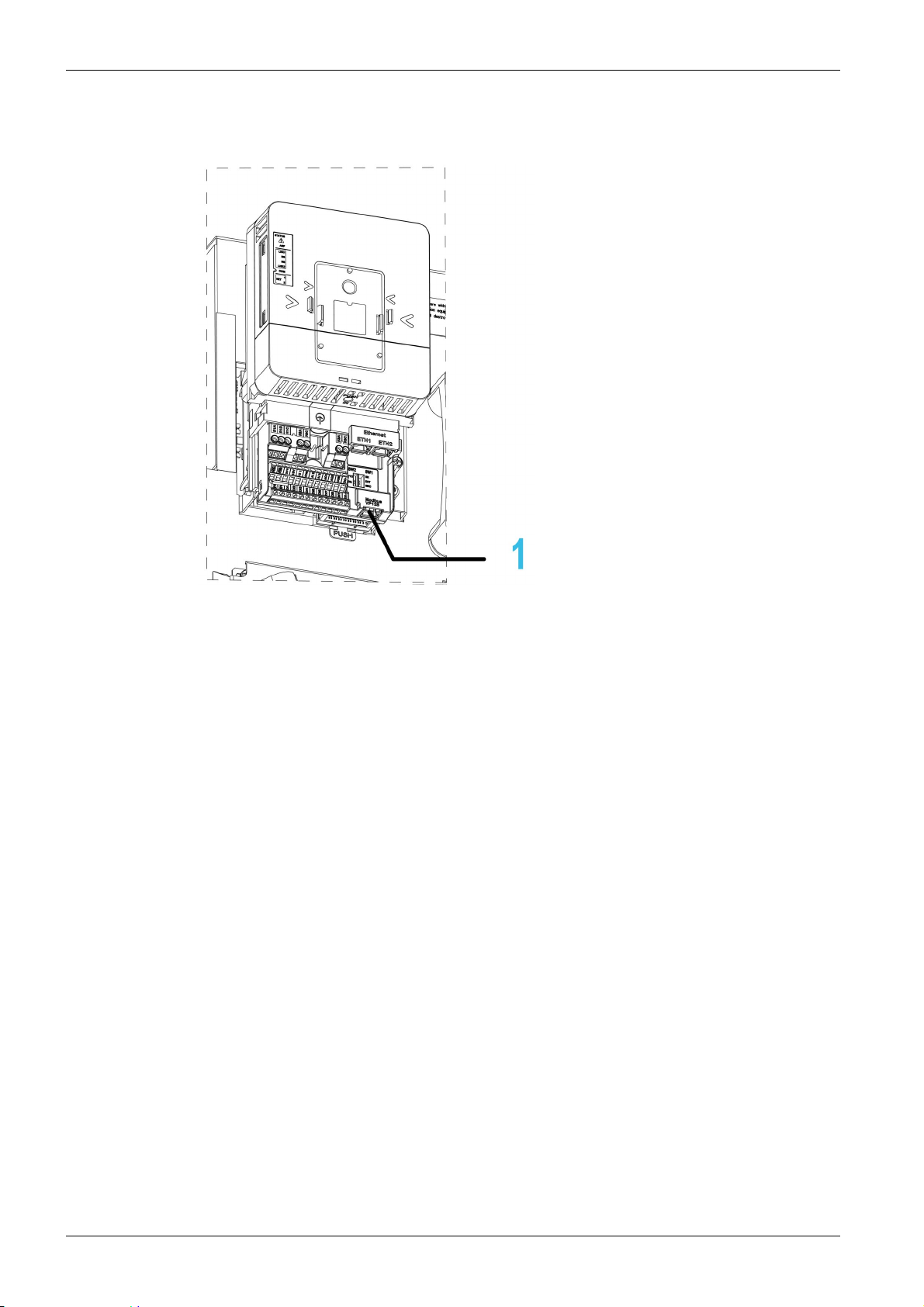
Hardware Overview
General
1 Modbus serial communication port
14
MFR24213 07/2020

Software Overview
Supported Modbus Functions
The drive supports the following Modbus functions:
Function Name Code Description Remarks
Read Holding
Registers
Write One Output Word
Write Multiple
Registers
Read/write Multiple
Registers
(Subfunction)
Read Device
Identification
Diagnostics
Presentation
Dec. Hex
03 03 hex Read N output words Maximum PDU length: 63 words
06 06 hex Write 1 output word −
16 10 hex Write N output word Maximum PDU length: 61 words
23 17 hex Read/write multiple
registers
43/14 2B hex/
0E hex
08 08 hex Diagnostics −
Encapsulated interface
transport/Read device
identification
Maximum PDU length: 20 words
(W), 20 words (R)
−
MFR24213 07/2020 15

Presentation
16
MFR24213 07/2020

A
Cyber Security
Introduction
ltivar Process ATV6000
Cyber Security
MFR24213 07/2020
Cyber Security
Chapter 2
Cyber Security
Cyber Security is a branch of network administration that addresses attacks on or by computer systems
and through computer networks that can result in accidental or intentional disruptions.
The objective of Cyber Security is to help provide increased levels of protection for information and physical
assets from theft, corruption, misuse, or accidents while maintaining access for their intended users.
No single Cyber Security approach is adequate. Schneider Electric recommends a defense-in-depth
approach. Conceived by the National Security Agency (NSA), this approach layers the network with
security features, appliances, and processes.
The basic components of this approach are:
Risk assessment
A security plan built on the results of the risk assessment
A multi-phase training campaign
Physical separation of the industrial networks from enterprise networks using a demilitarized zone
(DMZ) and the use of firewalls and routing to establish other security zones
System access control
Device hardening
Network monitoring and maintenance
This chapter defines the elements that help you configure a system that is less susceptible to cyber attacks.
For detailed information on the defense-in-depth approach, refer to the TVDA:
Vulnerability to Cyber Attacks in the Control Room (STN V2)
on the Schneider Electric website.
To submit a Cyber Security question, report security issues, or get the latest news from Schneider Electric,
visit the Schneider Electric website.
How Can I Reduce
Password Management
The system is secured thanks to several passwords:
Drive password must contain six characters (blanks are allowed)
Webserver password must contain:
A total of eight characters
At least one upper-case letter
At least one lower-case letter
At least one special character (for example, @, #, $)
No blank character
NOTE: After five unsuccessful login attempts, the access must be reactivated by the administrator.
Schneider Electric recommends to:
Modify the password every 90 days
Use a dedicated password (not related to your personal password)
NOTE: No responsibility is assumed by Schneider Electric for any consequences if anyone hacks your
product password and if you use the same password for personal usage.
Backing-up and Restoring the Software Configuration
To protect your data, Schneider Electric recommends backing-up the device configuration and keeping
your backup file in a safe place. The backup is available in the device DTM, using "load from device" and
"store to device" functions.
MFR24213 07/2020 17

Cyber Security
Remote Access to the Drive
When remote access is used between a device and the drive, ensure your network is secure
(VPN,Firewall…).
Machines, controllers, and related equipment are usually integrated into networks. Unauthorized persons
and malware may gain access to the machine as well as to other devices on the network/fieldbus of the
machine and connected networks via insufficiently secure access to software and networks.
UNAUTHORIZED ACCESS TO THE MACHINE VIA SOFTWARE AND NETWORKS
In your hazard and risk analysis, consider all hazards that result from access to and operation on the
network/fieldbus and develop an appropriate cybersecurity concept.
Verify that the hardware infrastructure and the software infrastructure into which the machine is
integrated as well as all organizational measures and rules covering access to this infrastructure
consider the results of the hazard and risk analysis and are implemented according to best practices
and standards covering IT security and cybersecurity, such as:
ISO/IEC 27000 series, ISO/ IEC 15408, IEC 62351, ISA/IEC 62443,
NIST Cybersecurity Framework,
Information Security Forum - Standard of Good Practice for Information Security,
Schneider Electric
Verify the effectiveness of your IT security and cybersecurity systems using appropriate, proven
methods.
Failure to follow these instructions can result in death, serious injury, or equipment damage.
WARNING
Recommended Cybersecurity Best Practices
.
Data Flow Restriction
To secure the access to the drive and limit the data flow, the use of a firewall device is required.
ConneXium Tofino Firewall Product
The ConneXium TCSEFEA Tofino Firewall is a security appliance that provides levels of protection against
cyber threats for industrial networks, automation systems, SCADA systems, and process control systems.
This Firewall is designed to permit or deny communications between devices connected to the external
network connection of the Firewall and the protected devices connected to the internal network connection.
The Firewall can restrict network traffic based on user defined rules that would permit only authorized
devices, communication types and services.
The Firewall includes built-in security modules and an off-line configuration tool for creating secure zones
within an industrial automation environment.
Control Command Restriction
To prevent unauthorized use of the command of the drive, it is possible to grant access to a limite d number
of IP address using the IP master parameter.
The parameter IP Master defines which device can command with the device. This parameter is available
in the device DTM.
Deactivation of unused functions
To avoid unauthorized access, it is advisable to deactivate unused functions.
Example: WebServer, Fast Device Replacement …
18
MFR24213 07/2020

A
ltivar Process ATV6000
Basics
MFR24213 07/2020
Basics
Chapter 3
Basics
What Is in This Chapter?
This chapter contains the following sections:
Section Topic Page
3.1 Profile 20
3.2 Modbus Functions 37
MFR24213 07/2020 19

Basics
Profile
Section 3.1
Profile
What Is in This Section?
This section contains the following topics:
Definition of a Profile 21
Functional Profiles Supported by the Drive 22
Functional Description 23
CIA402 Operating State Diagram 24
Description of Operating States 25
Summary 27
Cmd Register CMd 28
Stop Commands 29
Assigning Control Word Bits 30
[CIA402 State Reg] EtA 31
Starting Sequence 32
Starting Sequence for a Drive Powered by the Power Stage Supply 33
Starting Sequence for a Drive with Separate Control Stage 34
Starting Sequence for a Drive with Mains Contactor Control 36
Topic Page
20
MFR24213 07/2020

Definition of a Profile
Types of Profiles
There are 3 types of profile:
Communication profiles
Functional profiles
Application profiles
Communication Profile
A communication profile describes the characteristics of a bus or network:
Cables
Connectors
Electrical characteristics
Access protocol
Addressing system
Periodic exchange service
Messaging service
...
A communication profile is unique to a type of fieldbus (such as Modbus, PROFIBUS DP, and so on) and
is used by different types of devices.
Functional Profile
A functional profile describes the behavior of a type of device:
Functions
Parameters (such as name, format, unit, type, and so on.)
Periodic I/O variables
State chart
...
A functional profile is common to all members of a device family (such as variable speed drives, encoders,
I/O modules, displays, and so on).
They can feature common or similar parts. The standardized (IEC 61800-7) functional profiles of variable
speed drives are:
CiA402
PROFIDRIVE
CIP AC Drive
CiA402 device profile for drives and motion control represents the next stage of this standard development
and is now part of the IEC 61800-7 standard.
Basics
Application Profile
Application profile defines the services to be provided by the devices on a machine. For example, CiA DSP
417-2 V 1.01 part 2: CANopen application profile for lift control systems - virtual device definitions.
Interchangeability
The aim of communication and functional profiles is to achieve interchangeability of the devices connected
via the fieldbus.
MFR24213 07/2020 21

Basics
Functional Profiles Supported by the Drive
I/O Profile
Using the I/O profile simplifies PLC programming.
The I/O profile mirrors the use of the terminal strip for control by utilizing 1 bit to control a function.
The I/O profile for the drive can also be used when controlling via a fieldbus.The drive starts up as soon as
the run command is sent.15 bits of the control word (bits 1...15) can be assigned to a specific function.
This profile can be developed for simultaneous control of the drive via:
The terminals
The Modbus control word
The CANopen control word
Ethernet Modbus TCP embedded control word
The fieldbus module control word
The I/O profile is supported by the drive itself and therefore in turn by all the communication ports.
CiA402 Profile
The drive only starts up following a command sequence.
The control word is standardized.
5 bits of the control word (bits 11...15) can be assigned to a function.
The CiA402 profile is supported by the drive itself and therefore by all the communication ports.
The drive supports the velocity mode of CiA402 profile.
In the CiA402 profile, there are two modes that are specific to the drive and characterize commands and
references value management:
Separate [Separate] SEP
Not separate [Not separ.] SIm,
22
MFR24213 07/2020
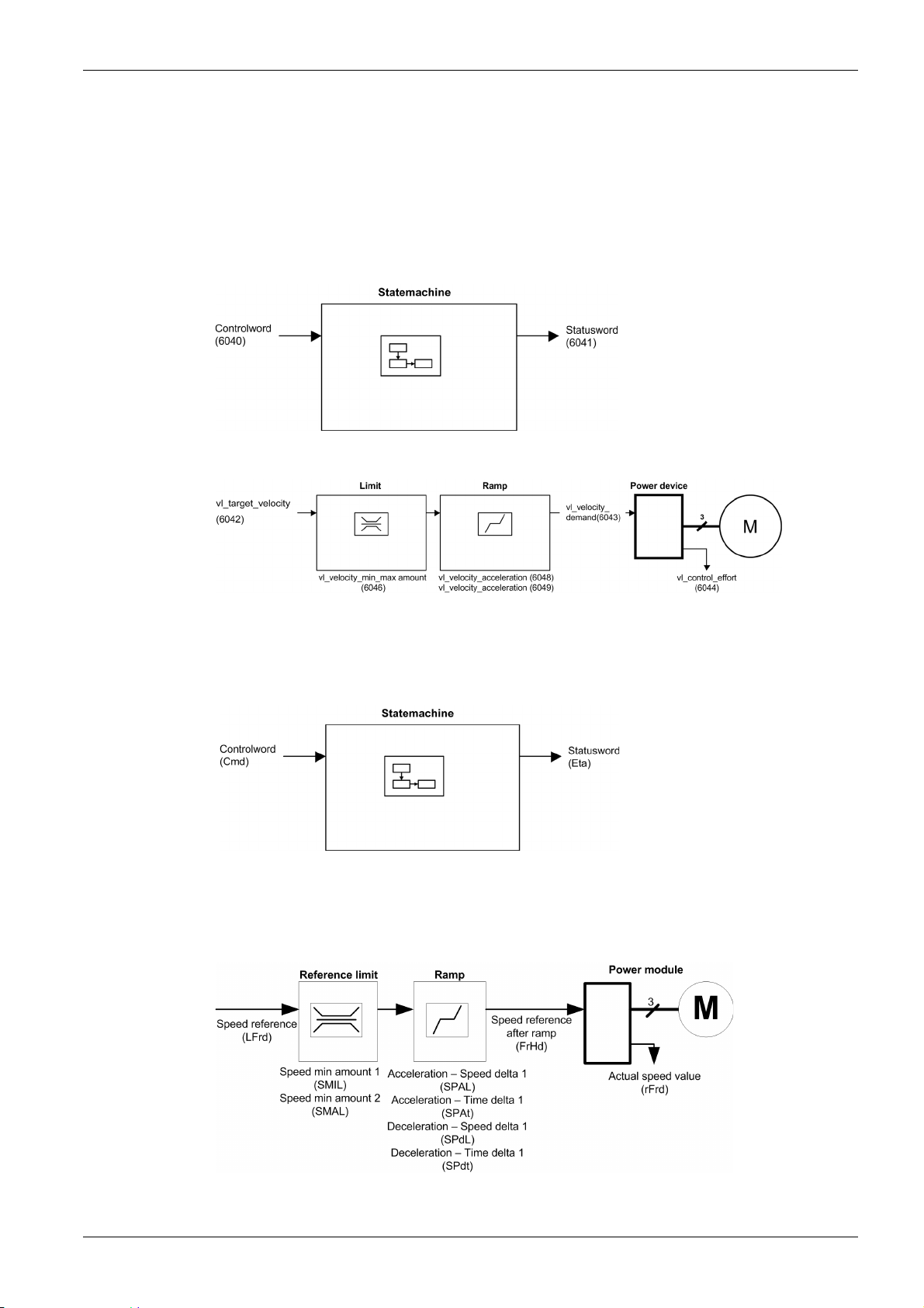
Functional Description
Introduction
Drive operation involves two main functions, which are illustrated in the diagrams below.
CiA402
The main parameters are shown with their CiA402 name and their CiA402/Drivecom index (the values in
brackets are the CANopen addresses of the parameter).
The following figure shows the control diagram for drive operation:
Simplified diagram for speed control in Velocity mode:
Basics
Altivar Drive
These diagrams translate as follows for the Altivar drive.
The following figure shows the control diagram for drive operation:
Simplified diagram for speed control in Velocity mode:
MFR24213 07/2020 23
Basics
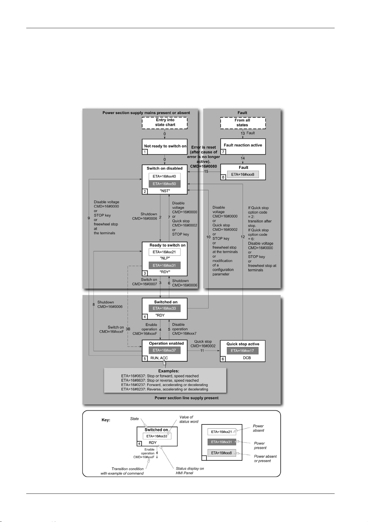
CIA402 Operating State Diagram
State Diagram
After switching on and when an operating mode is started, the product goes through a number of operating
states.
The state diagram (state machine) shows the relationships between the operating states and the state
transitions. The operating states are internally monitored and influenced by monitoring functions.
The following figure shows the CIA402 state diagram:
24
MFR24213 07/2020

Description of Operating States
Drive Operating State
The operating state of the drive changes depending on whether the control word [Cmd Register] CMd, is
sent or an event occurs (an error detection, for example).
The drive operating state can be identified by the value of the status word [CIA402 State Reg] EtA.
Operating State Description
1 - Not ready to switch
on
2 - Switch on disabled
3 - Ready to switch on
4 - Switched on
5 - Operation enabled
Basics
Initialization starts. This is a transient state invisible to the communication network.
The power stage is not ready to switch on.
The drive is locked, no power is supplied to the motor.
For a separate control stage, it is not necessary to supply the power.
For a separate control stage with mains contactor, the contactor is not closed.
The configuration and adjustment parameters can be modified.
The power stage is ready to switch on and awaiting power stage supply mains.
For a separate control stage, it is not necessary to supply the power stage, but the
system expects it in order to change to state 4 - Switched on.
For a separate control stage with mains contactor, the contactor is not closed.
The drive is locked, no power is supplied to the motor.
The configuration and adjustment parameters can be modified.
Power stage is switched on.
For a separate control stage, the power stage must be supplied.
For a separate control stage with mains contactor, the contactor is closed.
The drive is locked, no power is supplied to the motor.
The power stage of the drive is ready to operate, but voltage has not yet been
applied to the output.
The adjustment parameters can be modified.
If a configuration parameter is modified, the drive returns to the state 2 - Switch
on disable .
Power stage is enabled. The drive is in running state
For a separate control stage, the power stage must be supplied.
For a separate control stage with mains contactor, the contactor is closed.
The drive is unlocked, power is supplied to the motor.
The drive functions are activated and voltage is applied to the motor terminals.
If the reference value is zero or the Halt command is applied, no power is supplied
to the motor and no torque is applied. To perform [Auto tuning] tUn, the drive must
be in state 5 - Operation enabled.
The adjustment parameters can be modified.
The configuration parameters cannot be modified.
NOTE: The command 4 - Enable operation must be taken into consideration
only if the channel is valid. In particular, if the channel is involved in the command
and the reference value, transition 4 is possible only after the reference value has
been received once.
The reaction of the drive to a Disable operation command depends on the
value of the [SwitchOnDisable Stp] dOtd parameter:
If the [SwitchOnDisable Stp] dOtd parameter is set to 0, the drive changes to
operating state 4 - Switched on and stops in freewheel stop.
If the [SwitchOnDisable Stp] dOtd parameter is set to 1, the drive stops on
ramp and then changes to operating state 4 - Switched on.
MFR24213 07/2020 25

Basics
Operating State Description
6 - Quick stop active
The drive performs a fast stop and remains locked in the operating state 6-Quick
stop active. Before restarting the motor, it is required to go to the operating state
2-switch on disabled.
During fast stop, the drive is unlocked and power is supplied to the motor.
The configuration parameters cannot be modified.
The condition for transition 12 to state 2 - Switch on disabled depends on the
value of the parameter
[Quick stop Mode] QStd:
If the Quick stop mode parameter has the value FST2, the drive stops
according to the fast stop ramp and then changes to state 2 - Switch on
disabled .
If the Quick stop mode parameter has the value FST6, the drive stops
according to the fast stop ramp and then remains in state 6 - Quick stop
active until:
A Disable voltage command is received or
The STOP key is pressed or
A freewheel stop command via the digital input of the terminal.
7 - Fault reaction
active
8 - Fault
Transient state during which the drive performs an action corresponding to the
selected error response.
Error response terminated. Power stage is disabled.
The drive is locked, no power is supplied to the motor.
26
MFR24213 07/2020

Summary
Device Status Summary
Basics
Operating State Power Stage Supply for
Separate Control Stage
1 - Not ready to
switch on
2 - Switch on
disabled
3 - Ready to
switch on
4 - Switched on
5 - Operation
enabled
6 - Quick stop
active
7 - Fault reaction
active
8 - Fault
Not required No Yes
Not required No Yes
Not required No Yes
Required No Yes, return to 2 - Switch on
Required Yes No
Required Yes, during fast stop No
Depends on error response
configuration
Not required No Yes
Power Supplied to Motor Modification of Configuration
Parameters
disabled operating state
Depends on error
response configuration
−
NOTE:
Configuration parameters are described in communication parameter file as R/WS access type
parameters. Other parameters can be accessed whatever the operating state.
A Setting parameter can be accessed in all operating state of the drive.
MFR24213 07/2020 27

Basics
Cmd Register CMd
Bit Mapping of the Control Word
Bit 7 Bit 6 Bit 5 Bit 4 Bit 3 Bit 2 Bit 1 Bit 0
Fault reset Reserved
0 to 1
transition =
Error is
reset (after
cause of
error is no
longer
active)
Bit 15 Bit 14 Bit 13 Bit 12 Bit 11 Bit 10 Bit 9 Bit 8
Manufacturer
specific
assignable
(=0)
Manufacturer
specific
assignable
Reserved
(=0)
Manufacturer
specific
assignable
Reserved
(=0)
Manufacturer
specific
assignable
Enable
operation
1 = Run
command
Manufacturer
specific
0 = Forward
direction
asked
1= Reverse
direction
asked
Quick stop Enable
voltage
0 = Quick
stop active
Authorization
to supply AC
power
Reserved
(=0)
Reserved
(=0)
Switch on
Mains
contactor
control
Halt
0 = run
asked
1 = stop
asked
Command State
Transition
Shutdown
Switch on
Enable
operation
Disable
operation
Disable
voltage
Quick stop
Fault
reset
X: Value is of no significance for this command.
0→1: Command on rising edge.
2, 6, 8
3
4
5
7, 9, 10, 12
11
7, 10
15
Final
Operating
State
3 - Ready
to switch
on
4 Switched
on
5 Operation
enabled
4 Switched
on
2 - Switch
on
disabled
6 - Quick
stop
active
2 - Switch
on
disabled
2 - Switch
on
disabled
Bit 7 Bit 3 Bit 2 Bit 1 Bit 0 Example
Fault
Reset
X X 1 1 0 0006 hex
X X 1 1 1 0007 hex
X 1 1 1 1 000F hex
X 0 1 1 1 0007 hex
X X X 0 X 0000 hex
X X 0 1 X 0002 hex
0 → 1 X X X X 0080 hex
Enable
Operation
Quick
Stop
Enable
Voltage
Switch
On
Value
28
MFR24213 07/2020

Stop Commands
Halt Command
Freewheel Command
Basics
The Halt command enables movement to be interrupted without having to leave the 5 - Operation
enabled state. The stop is performed in accordance with the [Type of stop] Stt parameter.
If the Halt command is active, no power is supplied to the motor and no torque is applied.
Regardless of the assignment of the [Type of stop] Stt parameter [On Ramp] rMP, [Freewheel Stop]
nSt, the drive remains in the 5 - Operation enabled state.
A Freewheel Stop command using a digital input of the terminal or a bit of the control word assigned
to Freewheel Stop causes a change to operating state 2 - Switch on disabled.
MFR24213 07/2020 29

Basics
Assigning Control Word Bits
Function Codes
In the CiA402 profile, fixed assignment of a function input is possible using the following codes:
Bit Modbus Serial
Bit 11 C111
Bit 12 C112
Bit 13 C113
Bit 14 C114
Bit 15 C115
For example, to assign the external error to bit 13 of the fieldbus adapter, simply configure the [Ext Error
assign] ETF parameter with the [C113] C113 value.
Bit 11 is assigned by default to the operating direction command [Reverse Assign] rrS.
30
MFR24213 07/2020
 Loading...