

SCHNEIDER ELECTRIC ATV12H075M2 Instructions

2354235 11/2008
Altivar 12
Variable speed drives
for asynchronous motors
User manual
07/2018
BBV28581
www.schneider-electric.com

The information provided in this documentation contains general descriptions and/or technical characteristics of the
performance of the products contained herein. This documentation is not intended as a substitute for and is not to
be used for determining suitability or reliability of these products for specific user applications. It is the duty of any
such user or integrator to perform the appropriate and complete risk analysis, evaluation and testing of the products
with respect to the relevant specific application or use thereof. Neither Schneider Electric nor any of its affiliates or
subsidiaries shall be responsible or liable for misuse of the information contained herein. If you have any
suggestions for improvements or amendments or have found errors in this publication, please notify us.
No part of this document may be reproduced in any form or by any means, electronic or mechanical, including
photocopying, without express written permission of Schneider Electric.
All pertinent state, regional, and local safety regulations must be observed when installing and using this product.
For reasons of safety and to help ensure compliance with documented system data, only the manufacturer should
perform repairs to components.
When devices are used for applications with technical safety requirements, the relevant instructions must be
followed.
Failure to use Schneider Electric software or approved software with our hardware products may result in injury,
harm, or improper operating results.
Failure to observe this information can result in injury or equipment damage.
© 2013 Schneider Electric. All rights reserved.
BBV28581 07/2018

Contents
Energy savings
Speed control process regulating enables significant energy savings, particulary with pump and fan applications.
Furthermore some ATV12 functions enable to enhance these savings: [Motor control type] (Ctt) page
57, [Sleep/wake]
(tLS) page
74 and [PID feedback assignment] (PIF) page 72.
Contents ____________________________________________________________________________________________________ 3
Important information __________________________________________________________________________________________ 4
Before you begin______________________________________________________________________________________________ 5
Documentation structure________________________________________________________________________________________ 7
Software enhancements________________________________________________________________________________________ 8
Steps for setting up (also refer to Quick Start) _______________________________________________________________________ 9
Setup - Preliminary recommendations ____________________________________________________________________________ 10
Drive ratings ________________________________________________________________________________________________ 11
Dimensions and weights_______________________________________________________________________________________ 12
Mounting___________________________________________________________________________________________________ 13
Wiring _____________________________________________________________________________________________________ 16
Power terminals _____________________________________________________________________________________________ 20
Control terminals_____________________________________________________________________________________________ 23
Check list __________________________________________________________________________________________________ 29
Factory configuration _________________________________________________________________________________________ 30
Basic functions ______________________________________________________________________________________________ 31
Programming _______________________________________________________________________________________________ 32
Structure of parameter tables ___________________________________________________________________________________ 35
Function compatibility table ____________________________________________________________________________________ 36
Reference Mode rEF _________________________________________________________________________________________ 37
Monitoring mode MOn ________________________________________________________________________________________ 38
Configuration Mode ConF______________________________________________________________________________________ 44
Configuration Mode - MyMenu __________________________________________________________________________________ 45
Configuration Mode - Complete menu (FULL) ______________________________________________________________________ 47
Maintenance _______________________________________________________________________________________________ 100
Migration ATV11 - ATV12_____________________________________________________________________________________ 101
Diagnostics and Troubleshooting _______________________________________________________________________________ 108
Application notes ___________________________________________________________________________________________ 114
Short-circuit rating and branch circuit protection ___________________________________________________________________ 120
Organization tree ___________________________________________________________________________________________ 121
Parameter index ____________________________________________________________________________________________ 122
BBV28581 07/2018 3
Important information
The addition of this symbol to a Danger or Warning safety label indicates that an electrical hazard exists, which will result in
personal injury if the instructions are not followed.
This is the safety alert symbol. It is used to alert you to potential personal injury hazards. Obey all safety messages that follow
this symbol to avoid possible injury or death.
NOTICE
Read these instructions carefully, and look at the equipment to become familiar with the device before trying to install, operate, or maintain
it. The following special messages may appear throughout this documentation or on the equipment to warn of potential hazards or to call
attention to information that clarifies or simplifies a procedure.
DANGER
DANGER indicates an imminently hazardous situation, which, if not avoided, will result in death or serious injury.
WARNING
WARNING indicates a potentially hazardous situation, which, if not avoided, can result in death, serious injury or
equipment damage.
CAUTION
CAUTION indicates a potentially hazardous situation, which, if not avoided, can result in injury or equipment
damage.
NOTICE
NOTICE, used without the safety alert symbol, indicates a potentially hazardous situation which, if not avoided, can
result in equipment damage.
PLEASE NOTE
The word "drive" as used in this manual refers to the controller portion of the adjustable speed drive as defined by NEC.
Electrical equipment should be installed, operated, serviced, and maintained only by qualified personnel. No responsibility is assumed by
Schneider Electric for any consequences arising out of the use of this product.
© 2013 Schneider Electric. All Rights Reserved.
4 BBV28581 07/2018
Before you begin
Read and understand these instructions before performing any procedure with this drive.
DANGER
HAZARD OF ELECTRIC SHOCK, EXPLOSION, OR ARC FLASH
• Only appropriately trained persons who are familiar with and understand the contents of this manual and all other pertinent product
documentation and who have received safety training to recognize and avoid hazards involved are authorized to work on and with
this drive system. Installation, adjustment, repair, and maintenance must be performed by qualified personnel.
• The system integrator is responsible for compliance with all local and national electrical code requirements as well as all other
applicable regulations with respect to grounding of all equipment.
• Many components of the product, including the printed circuit boards, operate with mains voltage. Do not touch. Use only electrically
insulated tools.
• Do not touch unshielded components or terminals with voltage present.
• Motors can generate voltage when the shaft is rotated. Before performing any type of work on the drive system, block the motor shaft
to prevent rotation.
• AC voltage can couple voltage to unused conductors in the motor cable. Insulate both ends of unused conductors of the motor cable.
• Do not short across the DC bus terminals or the DC bus capacitors or the braking resistor terminals.
• Before performing work on the drive system:
- Disconnect all power, including external control power that may be present.
- Place a "Do Not Turn On" label on all power switches.
- Lock all power switches in the open position.
- Wait 15minutes to allow the DC bus capacitors to discharge. The DC bus LED is not an indicator of the absence of DC bus voltage
that can exceed 800Vdc.
- Measure the voltage on the DC bus between the DC bus terminals using a properly rated voltmeter to verify that the voltage is <
42Vdc.
- If the DC bus capacitors do not discharge properly, contact your local Schneider Electric representative.
• Install and close all covers before applying voltage.
Failture to follow these instructions will result in death or seìrious injury.
DANGER
UNINTENDED EQUIPMENT OPERATION
• Read and understand this manual before installing or operating the Altivar 12 drive.
• Any changes made to the parameter settings must be performed by qualified personnel.
Failure to follow these instructions will result in death or serious injury.
WARNING
DAMAGED DRIVE EQUIPMENT
Do not operate or install any drive or drive accessory that appears damaged.
Failure to follow these instructions can result in death, serious injury, or equipment damage.
BBV28581 07/2018 5

Before you begin
WARNING
LOSS OF CONTROL
• The designer of any control scheme must consider the potential failure modes of control paths and, for critical control functions,
provide a means to achieve a safe state during and after a path failure. Examples of critical control functions are emergency stop,
overtravel stop, power outage, and restart.
• Separate or redundant control paths must be provided for critical control functions.
• System control paths may include communication links. Consideration must be given to the implications of unanticipated
transmission delays or failures of the link.
• Observe all accident prevention regulations and local safety guidelines.
• Each implementation of the product must be individually and thoroughly tested for proper operation before being placed into service.
Failure to follow these instructions can result in death, serious injury, or equipment damage.
a. For USA: Additional information, refer to NEMA ICS 1.1 (latest edition), “Safety Guidelines for the Application, Installation, and Maintenance of Solid State Control”
and to NEMA ICS 7.1 (latest edition), “Safety Standards for Construction and Guide for Selection, Installation and Operation of Adjustable Speed Drive Systems.”
a
CAUTION
INCOMPATIBLE LINE VOLTAGE
Before turning on and configuring the drive, ensure that the line voltage is compatible with the supply voltage range shown on the drive
nameplate. The drive may be damaged if the line voltage is not compatible.
Failure to follow these instructions can result in injury or equipment damage.
Using motors in parallel
Set Motor control type Ctt page 57 to Std.
NOTICE
RISK OF DAMAGE TO THE MOTOR
Motor thermal protection is no longer provided by the drive. Provide an alternative means of thermal protection on every motor
Failure to follow these instructions can result in equipment damage
6 BBV28581 07/2018

Documentation structure
The following Altivar 12 technical documents are available on the Schneider Electric website (www.schneider-electric.com).
ATV12 Quick Start Guide (S1A56146)
The Quick Start describes how to wire and configure the drive to start motor quickly and simply for simple applications.
This document is delivered with the drive with an Annex (S1A58684) for Short Circuit Current Ratings (SCCR) and branch circuit protection.
ATV12 User manual (BBV28581)
This manual describes how to install, program and operate the drive.
ATV12 Modbus Communication manual (BBV28590)
This manual describes the assembly, connection to the bus or network, signaling, diagnostics, and configuration of the communicationspecific parameters via the 7 segment LED display.
It also describes the communication services of the Modbus protocol.
This manual includes all Modbus addresses. It explains the operating mode specific to communication (state chart).
ATV12P Installation manual (BBV28587)
This manual describes how to install the drive ATV12 baseplate following the conditions of acceptability.
ATV12 Parameters description file (BBV51917)
All the parameters are grouped together in an Excel file with the following data:
• Code
•Name
• Modbus Addresses
• Category
• Read/write access
• Type: signed numerical, unsigned numerical, etc.
•Unit
• Factory setting
• Minimum value
• Maximum value
• Display on the 7-segment integrated display terminal
• Relevant menu
This file offers the option of sorting and arranging the data according to any criterion chosen by the user.
BBV28581 07/2018 7

Software enhancements
Since it was first marketed, the Altivar ATV 12 has been equipped with additional functions. Software version V1.2 has now been updated
to V1.4. This documentation relates to version V1.4.
The software version appears on the rating plate attached to the side of the drive.
Enhancements made to version V1.2 in comparison to V1.1
• New parameters:
- Sleep threshold Offset SLE. See page 75
- PI feedback supervision threshold LPI. See page 76
- PI feedback supervision function time delay tPI. See page 76
- Maximum frequency detection hysteresis AP0. See page 76
- PI feedback supervision MPI. See page 76
- Fallback speed LFF. See page 76
- Time delay before automatic start for the overload fault FtO. See page 77
- Time delay before automatic start for the underload fault FtU. See page 78
- Selecting the operating mode MdE. See page 78
- Starting frequency of the auxiliary pump FOn. See page 78
- Time delay before starting the auxiliary pump tOn. See page 78
- Ramp for reaching the auxiliary pump nominal speed rOn. See page 78
- Auxiliary pump stopping frequency FOF. See page 78
- Time delay before the auxiliary pump stop command tOF. See page 79
- Ramp for auxiliary pump stopping rOF. See page 79
- Zero flow detection period nFd. See page 79
- Zero flow detection activation threshold FFd. See page 79
- Zero flow detection offset LFd. See page 79
• New menu Pump sub-menu PMP-. See page 77
• New quick REMOTE/LOCAL configuration switching using the embedded buttons. See page 34
• New wiring labels, LO+ and LO- instead of LO and CLO, see pages 18
.
.
.
.
.
.
.
.
.
.
.
.
.
.
.
.
.
.
. For pumping applications.
.
and 19.
Enhancements made to version V1.4 in comparison to V1.2
• New menu:
- External fault EtF-. See page 97
• New parameters:
- External fault assignment EtF. See page 97
- Stop type - external fault EPL. See page 97
• New detected fault:
- External detected fault by logic input EPF1. See page 111
These parameters are added to the standard ATV12 product offer.
. For External fault management by logic input.
.
.
.
8 BBV28581 07/2018
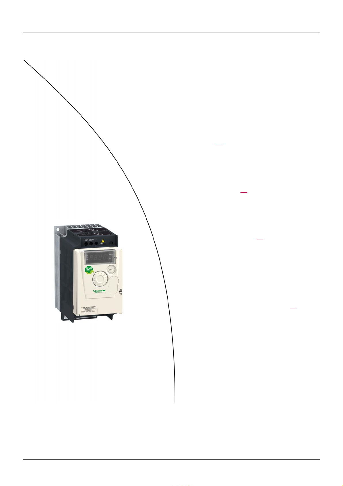
Steps for setting up (also refer to Quick Start)
1. Receive and inspect the drive
v Check that the part number printed on the label is the same as that on the
purchase order.
v Remove the Altivar from its packaging and check that it has not been damaged
in transit.
2. Check the line voltage
v Check that the line voltage is compatible with the voltage
range of the drive (page 11
).
3. Mount the drive
v Mount the drive in accordance with the instructions
in this document (page 13
).
v Install any options required.
Steps 2 to 4 must
be performed with
the power off.
4. Wire the drive
(page 20)
v Connect the motor, ensuring that its
connections correspond to the voltage.
v Connect the line supply, after making
sure that the power is off.
v Connect the control part.
5. Configure the drive (page 32)
v Apply input power to the drive but
do not give a run command.
v Set the motor parameters
(in Conf mode) only if the factory
configuration of the drive is not
suitable.
v Perform auto-tuning.
6. Start
BBV28581 07/2018 9

Setup - Preliminary recommendations
Before switching-on the drive
DANGER
UNINTENDED EQUIPMENT OPERATION
Ensure that all logic inputs are inactive to help prevent an accidental startup.
Failure to follow these instructions will result in death or serious injury.
Before configuring the drive
DANGER
UNINTENDED EQUIPMENT OPERATION
• Read and understand this manual before installing or operating the Altivar 12 drive.
• Any changes made to the parameter settings must be performed by qualified personnel.
• Ensure that all logic inputs are inactive to help prevent an accidental startup when modifying parameters.
Failure to follow these instructions will result in death or serious injury.
Using the drive with motor having a different size
The motor could have different rating than drive. In case of smaller motor, there is no specific calculation. The motor current has to be set
on Motor thermal current ItH parameter page 94
on a 2.2 kW (3 HP) drive) it is necessary to ensure motor current and actual motor power will not pass over nominal power of drive.
. In case of higher size of motor, possible up to 2 sizes (example is using a 4 kW (5.5 HP)
Line contactor
NOTICE
RISK OF DAMAGE TO THE DRIVE
• Avoid operating the contactor frequently to avoid premature aging of the filter capacitors.
• Power cycling must be MORE than 60 seconds.
Failure to follow these instructions can result in equipment damage.
Use with a smaller rated motor or without a motor
• In factory settings mode, Output Phase loss OPL page 94 is active (OPL set to YES). To check the drive in a test or maintenance
environment without having to switch to a motor with the same rating as the drive (useful in the case of high power drives), deactivate
Output Phase loss OPL (OPL set to nO).
•Set Motor control type Ctt page 57
to Std in Motor control menu drC-.
NOTICE
RISK OF DAMAGE TO THE MOTOR
Motor thermal protection will not be provided by the drive if the motor rating current is less than 20% of the rated drive current. Provide
an alternative means of thermal protection.
Failure to follow these instructions can result in equipment damage.
10 BBV28581 07/2018

Drive ratings
2 F3
possible values
1
2
3
physical size 1
physical size 2
physical size 3
possible values
FCFlat
Compact
1
2
3
100 V 1-phase
200 V 1-phase
200 V 3-phase
possible values
1-phase supply voltage: 100…120 V 50/60 Hz
For 3-phase Output 200/240 V motors
Motor Line supply (input) Drive (output) Reference
Power indicated
on plate (1)
kW HP A A kVA W A A A
0.18 0.25 6 5 1 18 1.4 2.1 2.3 ATV12H018F1 1C1
0.37 0.5 11.4 9.3 1.9 29 2.4 3.6 4 ATV12H037F1 1C1
0.75 1 18.9 15.7 3.3 48 4.2 6.3 6.9 ATV12H075F1 2C1
Maximum line current Apparent
power
at 100 V at 120 V
Power
dissipated
at nominal
current (1)
Nominal
current
In
Max. transient
current for
60 s 2 s
(2)
1-phase supply voltage: 200…240 V 50/60 Hz
For 3-phase Output 200/240 V motors
Motor Line supply (input) Drive (output) Reference
Power indicated
on plate (1)
kW HPAAkVAW A A A
0.18 0.25 3.4 2.8 1.2 18 1.4 2.1 2.3 ATV12H018M2 1C2
0.37 0.5 5.9 4.9 2 27 2.4 3.6 4 ATV12H037M2 1C2
0.55 0.75 8 6.7 2.8 34 3.5 5.3 5.8 ATV12H055M2 1C2
0.75 1 10.2 8.5 3.5 44 4.2 6.3 6.9 ATV12H075M2 1C2
1.5 2 17.8 14.9 6.2 72 7.5 11.2 12.4 ATV12HU15M2 2C2
2.2 3 24 20.2 8.4 93 10 15 16.5 ATV12HU22M2 2C2
Maximum line current Apparent
power
at 200 V at 240 V
Power
dissipated
at nominal
current (1)
Nominal
current
In
Max. transient
current for
60 s 2 s
(2)
3-phase supply voltage: 200…240 V 50/60 Hz
For 3-phase Output 200/240 V motors
Size
(3)
Size
(3)
Motor Line supply (input) Drive (output) Reference
Power indicated
on plate (1)
kW HPAAkVAWA A A
0.18 0.25 2 1.7 0.7 16 1.4 2.1 2.3 ATV12H018M3 1C3
0.37 0.5 3.6 3 1.2 24 2.4 3.6 4 ATV12H037M3 1C3
0.75 16.3 5.3 2.2 41 4.2 6.3 6.9 ATV12H075M3 1C3
1.5 2 11.1 9.3 3.9 73 7.5 11.2 12.4 ATV12HU15M3 2F3
2.2 3 14.9 12.5 5.2 85 10 15 16.5 ATV12HU22M3 2F3
3 4 19 15.9 6.6 94 12.2 18.3 20.1 ATV12HU30M3 3F3
4 5.5 23.8 19.9 8.3 128 16.7 25 27.6 ATV12HU40M3 3F3
(1)These power ratings are for a switching frequency of 4 kHz, in continuous operation. The
switching frequency is adjustable from 2 to 16 kHz.
Above 4 kHz, the drive will reduce the switching frequency if an excessive temperature rise
occurs. The temperature rise is detected by a probe in the power module. Nonetheless,
derating should be applied to the nominal drive current if continuous operation above 4 kHz
is required:
• 10% derating for 8 kHz
• 20% derating for 12 kHz
• 30% derating for 16 kHz
(3)Size description
Maximum line current Apparent
power
at 200 V at 240 V
Power
dissipated
at nominal
current (1)
Nominal
current
In
Max. transient
current for
60 s 2 s
(2)Reference description,
(2)
example: ATV12HU15M3
ATV12: Altivar 12;
H: product on heatsink;
U15: drive power rating,
see nCU parameter page 41
M3: drive voltage rating,
see UCAL parameter page 41
Size
(3)
;
.
BBV28581 07/2018 11

Dimensions and weights
ATV12H018F1, 018M2, 037F1, 037M2, 037M3, 018M2, 018M3, 055M2, 075M2
ATV12H075F1, U15M2, U22M2, U15M3, U22M3
ATV12H
018F1
018M2
018M3
037F1
037M2
037M3
055M2
075M2
075M3
ATV12H
075F1
U15M2
U22M2
U15M3
U22M3
a
mm
(in.)
72
(2.83)
72
(2.83)
72
(2.83)
a
mm
(in.)
105
(4.13)
105
(4.13)
105
(4.13)
b
mm
(in.)
142
(5.59)
130
(5.12)
130
(5.12)
b
mm
(in.)
130
(5.12)
130
(5.12)
130
(5.12)
c
mm
(in.)
102.2
(4.02)60(2.36)
121.2
(4.77)60(2.36)
131.2
(5.17)60(2.36)
c
mm
(in.)
156.2
(6.15)93(3.66)
156.2
(6.15)93(3.66)
131.2
(5.17)93(3.66)
G
mm
(in.)
G
mm
(in.)
H
mm
(in.)
131
(5.16)
120
(4.72)
120
(4.72)
H
mm
(in.)
120
(4.72)
120
(4.72)
120
(4.72)
H1
mm
(in.)
143
(5.63)
143
(5.63)
143
(5.63)
H1
mm
(in.)
142
(5.59)
142
(5.59)
143
(5.63)
Ø
mm
(in.)
2 x 5
(2 x 0.20)
2 x 5
(2 x 0.20)
2 x 5
(2 x 0.20)
Ø
mm
(in.)
2 x 5
(2 x 0.20)
2 x 5
(2 x 0.20)
2 x 5
(2 x 0.20)
For
screws
M4
M4
M4
For
screws
M4
M4
M4
Weight
kg
(lb)
0.7
(1.5)
0.8
(1.8)
0.8
(1.8)
Weight
kg
(lb)
1.3
(2.9)
1.4
(3.1)
1.2
(2.6)
ATV12HU30M3, U40M3
ATV12H
U30M3
U40M3
a
mm
(in.)
140
(5.51)
b
mm
(in.)
170
(6.69)
c
mm
(in.)
141.2
(5.56)
G
mm
(in.)
126
(4.96)
H
mm
(in.)
159
(6.26)
H1
mm
(in.)
184
(7.24)
Ø
mm
(in.)
4 x 5
(2 x 0.20)
For
screws
M4
Weight
kg
(lb)
2.0
(4.4)
12 BBV28581 07/2018
Mounting
50 mm
(2 in)
d
d
50 mm
(2 in)
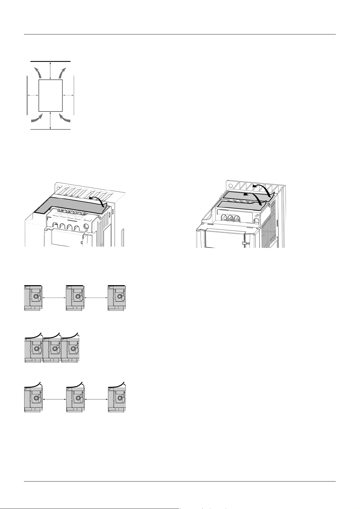
Type A mounting
Free space 50 mm (2 in.) on each side, with vent cover fitted. Mounting type A is
suitable for drive operation at surrounding air temperature less than or equal to 50°C
(122°F) and 40°C (104°F) for UL.
50 mm
(2 in.)
50 mm
(2 in.)
Type B mounting
Drives mounted side-by-side, vent cover should be removed.
Type C mounting
Free space 50 mm (2 in.) on each side. Vent cover should be removed for operation at
surrounding air temperature above 50°C (122°F).
With these types of mounting, the drive can be used up to an ambient temperature of 50°C (122°F), with a switching frequency of 4 kHz.
Fanless drives need derating.
50 mm
(2 in.)
50 mm
(2 in.)
Mounting and temperature conditions
Install the unit vertically, at ± 10°.
Do not place it close to heating elements.
Leave sufficient free space to ensure that the air required for cooling purposes can circulate from the bottom to the
top of the unit.
Free space in front of unit: 10 mm (0.4 in.) minimum.
Free space on each side (represented by the letter "d" on the graph): 50mm (2 in.) minimum. In Type B mounting
(see below in mounting types), the free space is reduced to 0mm (0 in.).
It is recommended that the drive is installed on a dissipative surface.
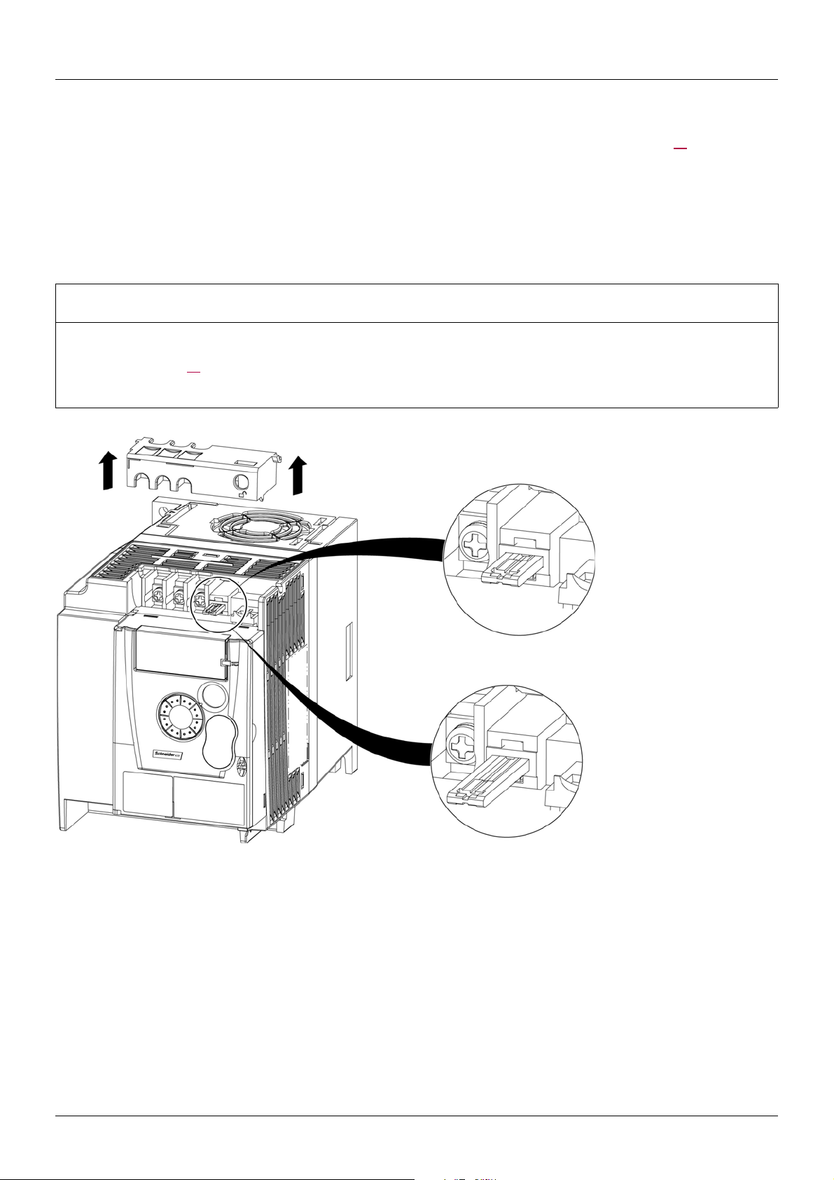
Removing the vent cover(s)
Mounting types
BBV28581 07/2018 13

Mounting
40°C (104°F) mounting types A and C
50°C (122°F) mounting type C mounted on metal plate (1)
Switching frequency in kHz
40°C (104°F) mounting type B
60°C (140°F) mounting types A, B and C (1)
Switching frequency in kHz
ATV12HU
ppM2, ATV12H075F1, ATV12HU15M3 to ATV12HU40M3
50°C (122°F) mounting types A, B and C
60°C (140°F) mounting type C mounted on metal plate (1)
Derating curves
Derating curves for the nominal drive current (In) as a function of temperature, switching frequency and mounting type.
ATV12H0
ppM2, ATV12H0ppM3, ATV12H018F1 to ATV12H037F1
For intermediate temperatures (for example 55°C (131°F)), interpolate between 2 curves.
(1) Not UL recognized.
Bus voltage measurement procedure
DANGER
HAZARD OF ELECTRIC SHOCK, EXPLOSION, OR ARC FLASH
Read and understand the precautions in “Before you begin” on page 5 before performing this procedure.
Failure to follow these instructions will result in death or serious injury.
14 BBV28581 07/2018
Mounting
1
2
2
2
2
1
1
2
2
1
2
2
1. 2 mounting screws
2. 4 x M4 screws for attaching EMC clamps
Size 3, plate reference VW3A9525:
ATV12
pU30M3 and ATV12pU40M3
Size 2, plate reference VW3A9524:
ATV12H075F1, ATV12HU
ppM2, ATV12pU15M3,
ATV12
pU22M3
Size 1, plate reference VW3A9523:
ATV12H018F1, ATV12H037F1, ATV12P037F1,
ATV12H018M2, ATV12
p0ppM2, ATV12p0ppM3
1
2
2
2
2
1
Installing the EMC plates
EMC mounting plate: size 1 VW3A9523, size 2 VW3A9524 or size 3 VW3A9525 to be ordered
separately
Mount the EMC mounting plate to the holes in the ATV12 using the 2 screws supplied, as shown in the drawings below.
BBV28581 07/2018 15
Wiring
Recommendations
Keep the power cables separate from control circuits with low-level signals (detectors, PLCs, measuring apparatus, video, telephone).
Always cross control and power cables at 90° if possible.
Power and circuit protection
Follow wire size recommendations according to local codes and standards.
Before wiring power terminals, connect the ground terminal to the grounding screws located below the output terminals (see Access to the
motor terminals if you use ring terminals, page 21
.
The drive must be grounded in accordance with the applicable safety standards. ATV12
such the leakage current is over 3.5 mA.
When upstream protection by means of a "residual current device" is required by the installation standards, a type A circuit breaker should
be used for 1-phase drives and type B for 3-phase drives. Choose a suitable model incorporating:
• HF current filtering
• A time delay which prevents tripping caused by the load from stray capacitance on power-up. The time delay is not possible for 30 mA
devices. In this case, choose devices with immunity against accidental tripping, for example RCDs with SI type leakage current
protection.
If the installation includes several drives, provide one "residual current device" per drive.
ppppM2 drives have an internal EMC filter, and as
Control
For control and speed reference circuits, it is recommended to use shielded twisted cables with a pitch of between 25 and 50 mm (1 and
2 in.), connecting the shield to ground as outlined on page 26
.
Length of motor cables
For motor cable lengths longer than 50 m (164 ft) for shielded cables and longer than 100 m (328 ft) for unshielded cables, please use motor
chokes.
For accessory part numbers, refer to the catalog.
Equipment grounding
Ground the drive according to local and national code requirements. A minimum wire size of 10 mm² (6 AWG) may be required to meet
standards limiting leakage current.
.
DANGER
HAZARD OF ELECTRIC SHOCK, EXPLOSION, OR ARC FLASH
• The drive panel must be properly grounded before power is applied.
• Use the provided ground connecting point as shown in the figure below.
Failure to follow these instructions will result in death or serious injury.
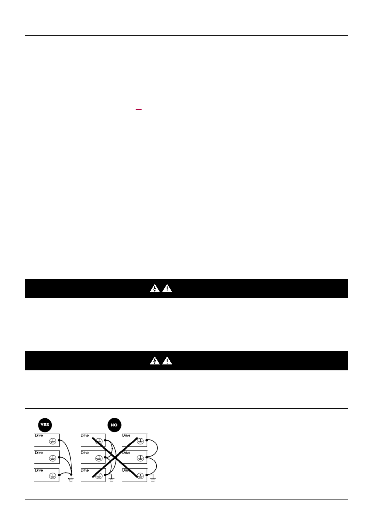
DANGER
ATV12H075F1, ATV12H075M2 AND ATV12H075M3 - GROUND CONTINUITY HAZARD
An anodized heatsink can create an insulation barrier to the mounting surface. Ensure that you follow the recommended grounding
connections.
Failure to follow these instructions will result in death or serious injury.
• Ensure that the resistance of the ground is one ohm or less.
• When grounding several drives, you must connect each one
directly, as shown in the figure to the left.
• Do not loop the ground cables or connect them in series.
16 BBV28581 07/2018

Wiring
WARNING
RISK OF DRIVE DESTRUCTION
• The drive will be damaged if input line voltage is applied to the output terminals (U/T1,V/T2,W/T3).
• Check the power connections before energizing the drive.
• If replacing another drive, verify that all wiring connections to the drive comply with wiring instructions in this manual.
Failure to follow these instructions can result in death, serious injury or equipment damage.
WARNING
INADEQUATE OVERCURRENT PROTECTION
• Overcurrent protective devices must be properly coordinated.
• The Canadian Electrical Code and the National Electrical Code require branch circuit protection. Use the fuses recommended in the
Quick Start Annex (S1A58684) delivered with the drive.
• Do not connect the drive to a power feeder whose short-circuit capacity exceeds the drive short-circuit current rating listed in the
Quick Start Annex (S1A58684) delivered with the drive.
Failure to follow these instructions can result in death, serious injury or equipment damage.
BBV28581 07/2018 17
Wiring
1-phase supply 100...120 V
3-phase supply 200...240 V
ATV12ppppF1
1-phase supply 200...240 V
ATV12
ppppM2
ATV12
ppppM3
Source
3-phase
motor
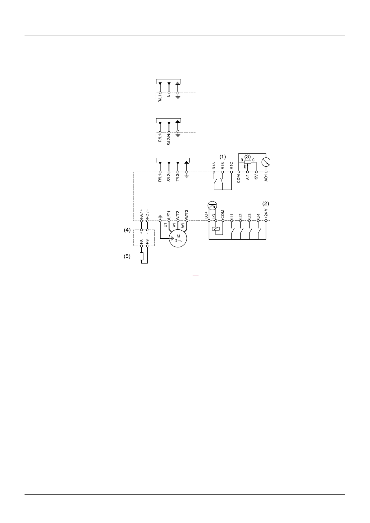
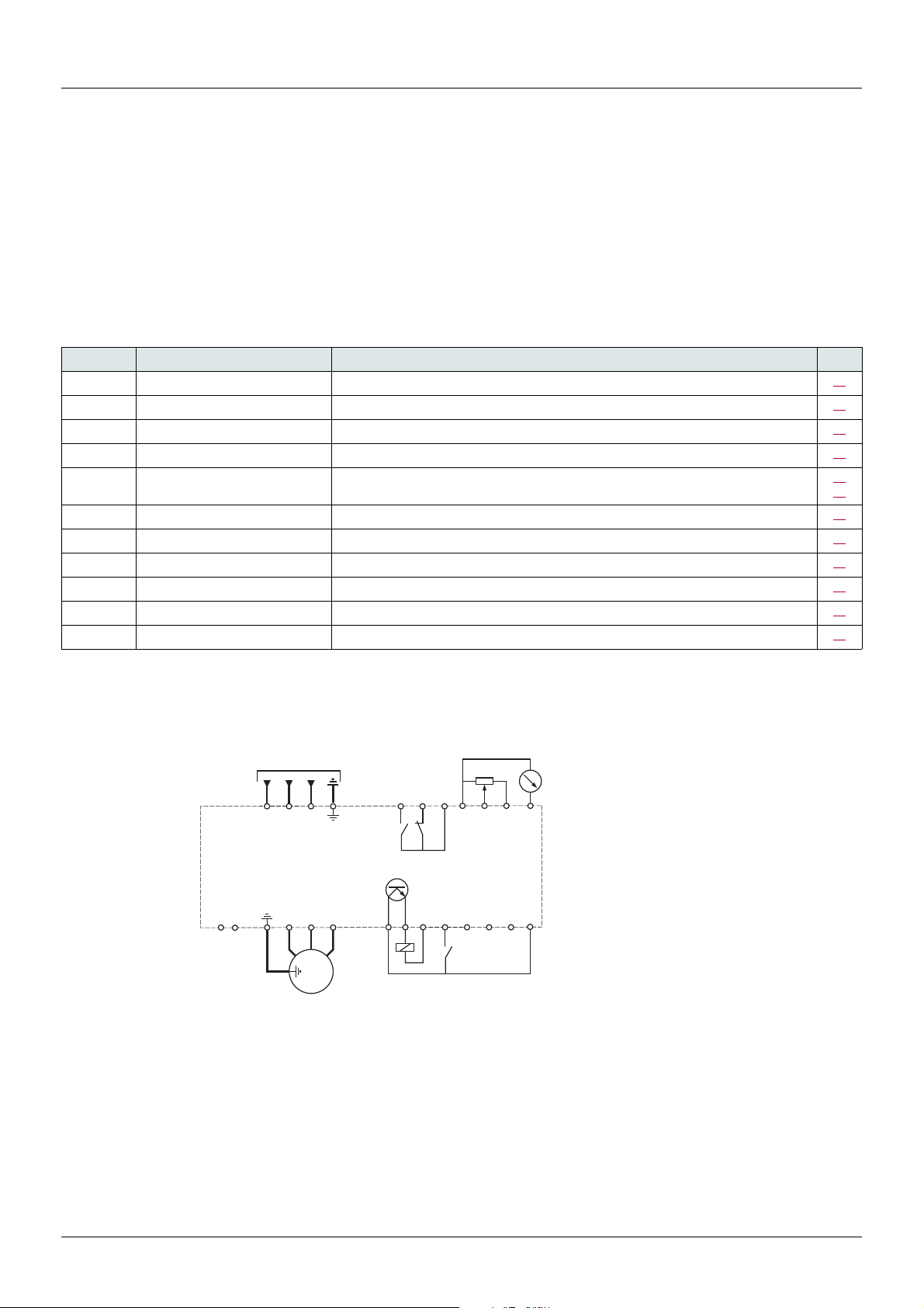
General wiring diagram
(1)R1 relay contacts, for remote indication of the drive status, see page 52
(2) Internal + 24 V c. If an external source is used (+ 30 V c maximum), connect the 0 V of the source to the COM terminal, and do not
use the + 24 V
(3) Reference potentiometer SZ1RV1202 (2.2 k
(4) Optional braking module VW3A7005
(5) Optional braking resistor VW3A7
Note:
If intermittent OSF code appear, set Relay R1 to FLt and it can be connected to upstream protection to avoid overvoltage in the
drive. In this case LO1 can be used for others drive status see page 53
c terminal on the drive.
ppp or other acceptable resistor. See the possible resistor values in the catalog.
• Use transient voltage surge suppressors for all inductive circuits near the drive or coupled to the same circuit (relays, contactors,
solenoid valves, etc.).
• The ground terminal (green screw) is located on the opposite side in comparison with its position on the ATV11 (see wiring trap label).
) or similar (10 kmaximum).
18 BBV28581 07/2018

Wiring
Input 120 V
Output 240 V
Input 240 V
Output 240 V
Input 240 V
Output 240 V
Wiring labels
ATV12HpppF1
ATV12H
ATV12H
pppM2
pppM3
BBV28581 07/2018 19
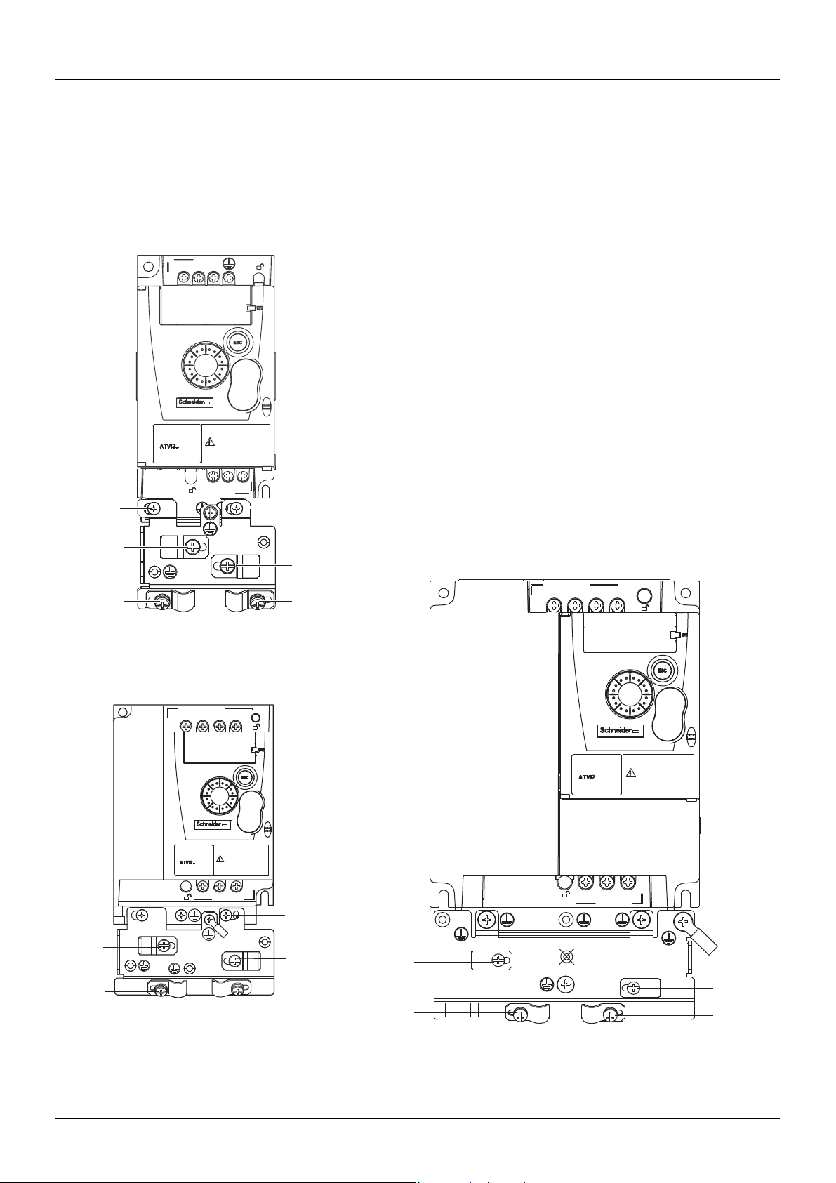
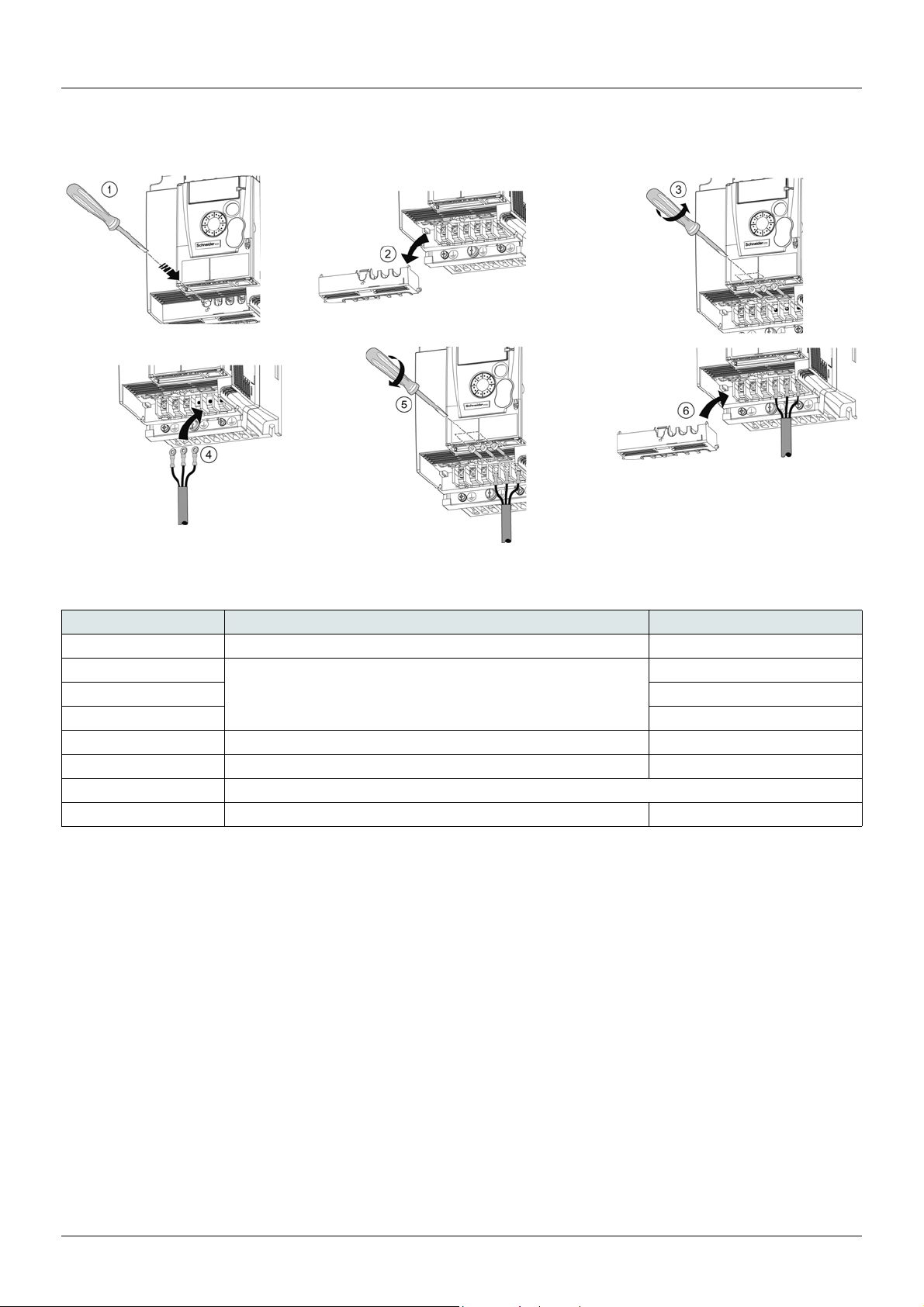
Power terminals
Wiring trap
Line supply is at the top of the drive, the motor power supply is at the bottom of the drive. The power terminals can be accessed without
opening the wiring trap if you use stripped wire cables.
Access to the power terminals
Access to the terminals if you use stripped wire cables
DANGER
HAZARD OF ELECTRIC SHOCK, EXPLOSION, OR ARC FLASH
Replace the wiring trap before applying power.
Failure to follow these instructions will result in death or serious injury.
CAUTION
RISK OF BODY INJURY
Use pliers to remove snap-off of the wiring trap.
Failure to follow these instructions can result in injury or equipment damage.
Access to the line supply terminals to connect ring terminals
A) IT jumper on ATV12ppppM2
B) Grounding screws located below the output terminals.
20 BBV28581 07/2018
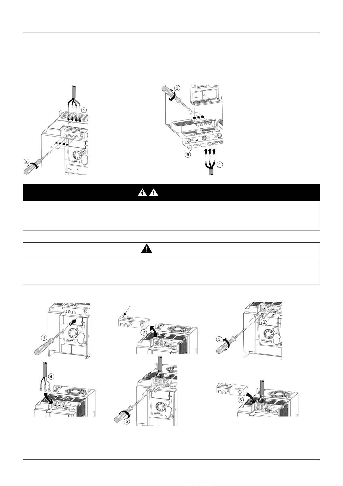
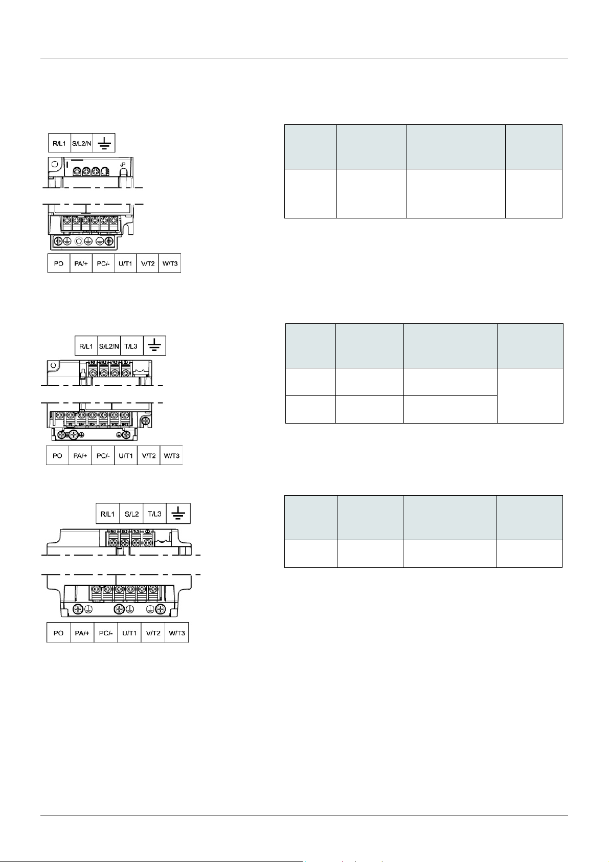
Power terminals
Access to the motor terminals if you use ring terminals
Characteristics and functions of power terminals
Terminal Function For ATV12
t
R/L1 - S/L2/N Power supply 1-phase 100…120 V
R/L1 - S/L2/N 1-phase 200…240 V
R/L1 - S/L2 - T/L3 3-phase 200…240 V
PA/+ + output (dc) to the braking module DC Bus (visible part on wiring trap) All ratings
PC/– – output (dc) to the braking module DC Bus (visible part on wiring trap) All ratings
PO Not used
U/T1 - V/T2 - W/T3 Outputs to the motor All ratings
Ground terminal All ratings
BBV28581 07/2018 21
Power terminals
ATV12H
Applicable wire
size (1)
Recommended
wire size (2)
Tightening
torque (3)
mm² (AWG) mm² (AWG) N·m (lb.in)
018F1
037F1
0
ppM2
0
ppM3
2 to 3.5
(14 to 12)
2
(14)
0.8 to 1
(7.1 to 8.9)
ATV12H 018F1, 037F1, 0ppM2, 0ppM3
ATV12H 075F1, U
ppM2, U15M3, U22M3
ATV12H U30M3, U40M3
(1)The value in bold corresponds to the minimum wire gauge to permit secureness.
(2)75°C (167 °F) copper cable (minimum wire size for rated use)
(3)Recommended to maximum value.
ATV12H
Applicable
wire size (1)
Recommended
wire size (2)
Tightening
torque (3)
mm² (AWG) mm² (AWG) N·m (lb.in)
075F1
U
ppM2
3.5 to 5.5
(12 to 10)
5.5
(10)
1.2 to 1.4
(10.6 to 12.4)
U15M3
U22M3
2 to 5.5
(14 to 10)
2 (14) for U15M3
3.5 (12) for U22M3
ATV12H
Applicable
wire size (1)
Recommended
wire size (2)
Tightening
torque (3)
mm² (AWG) mm² (AWG) N·m (lb.in)
U30M3
U40M3
5.5 (10) 5.5 (10)
1.2 to 1.4
(10.6 to 12.4)
Arrangement of the power terminals
22 BBV28581 07/2018
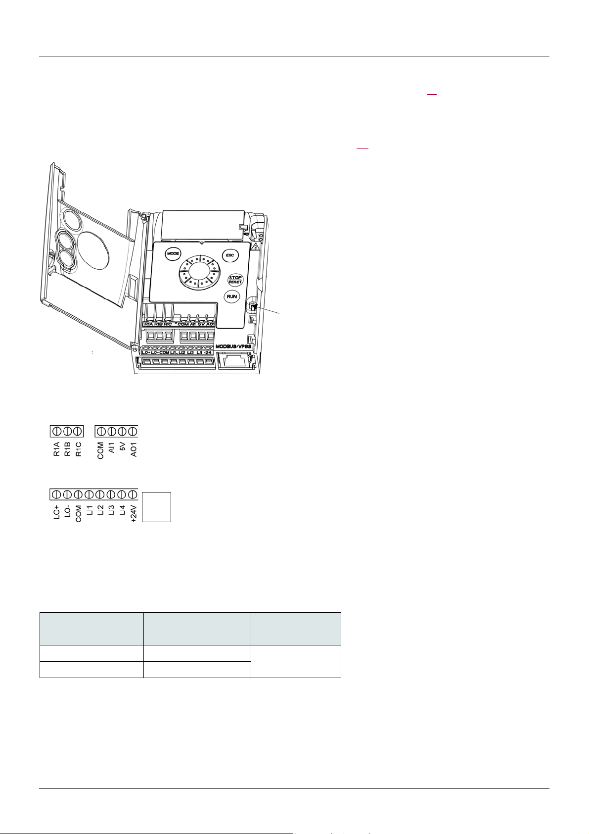
Control terminals
It is possible to lock the
cover with a lead seal.
Note: To connect cables, use a
slotted screwdriver 0.6 x 3.5.
R1A
R1B
R1C
COM
AI1
5V
AO1
LO+
LOCOM
LI1
LI2
LI3
LI4
+24V
RJ45
RJ45
(1)The value in bold corresponds to the minimum wire gauge to permit secureness.
(2)Recommended to maximum value.
ATV12 Control terminals Applicable wire size (1) Tightening torque (2)
mm² (AWG) N·m (lb.in)
R1A, R1B, R1C 0.75 to 1.5 (18 to 16)
0.5 to 0.6 (4.4 to 5.3)
Other terminals 0.14 to 1.5 (26 to 16)
Normally open (NO) contact of the relay
Normally closed (NC) contact of the relay
Common pin of the relay
COMmon of analog and logic I/Os
Analog Input
+5VDC supply provided by the drive
Analog Output
Logic Output (collector)
Common of the Logic Output (emitter)
COMmon of analog and logic I/Os
Logic Input
Logic Input
Logic Input
Logic Input
+24 VDC supply provided by the drive
Connection for SoMove software, Modbus network or remote display.
Keep the control circuits away from the power cables. For control and speed reference circuits, it is recommended to use shielded twisted
cables with a pitch of between 25 and 50 mm (1 and 2 in.), connecting the shielding as outlined on page 26
Access to the control terminals
To access the control terminals, open the cover.
Note: For information regarding HMI button functions, see "HMI description" on page 32.
.
Arrangement of the control terminals
BBV28581 07/2018 23

Control terminals
Characteristics and functions of the control terminals
Terminal Function Electrical characteristics
R1A NO contact of the relay Min. switching capacity:
• 5 mA for 24 V
R1B NC contact of the relay
R1C Common pin of the relay
COM Common of analog and logic I/Os
AI1 Voltage or current analog input • resolution: 10 bits
5V +5 VDC power supply for reference potentiometer • precision: ± 5%
AO1 Voltage or current analog output (collector) • resolution: 8 bits
LO+ Logic output • voltage: 24 V (maximum 30 V)
LO- Common of the logic output (emitter)
LI1
LI2
LI3
LI4
+24V + 24 VDC supply provided by the drive + 24 VDC –15% +20% protected against short-circuits and
Logic inputs Programmable logic inputs
Maximum switching capacity:
• 2 A for 250 V
(cos = 0.4 and L/R = 7 ms)
• 3 A for 250 V
(cos = 1 and L/R = 0)
• response time: 30 ms maximum.
• precision: ± 1% at 25°C (77°F)
• linearity: ± 0.3% (of full scale)
• sampling time: 20 ms ± 1 ms
Analog voltage input 0 to +5 V or 0 to +10 V
(maximum voltage 30 V) impedance: 30 k
Analog current input x to y mA, impedance: 250
• maximum current: 10 mA
• precision: ± 1% at 25°C (77°F)
• linearity: ± 0.3% (of full scale)
• refresh time: 4 ms (maximum 7 ms)
Analog voltage output: 0 to +10 V (maximum voltage +1%)
• minimum output impedance: 470
Analog current output: x to 20 mA
• maximum output impedance: 800
• impedance: 1 k, maximum 10 mA (100 mA in open collector)
• linearity: ± 1%
• refresh time: 20 ms ± 1 ms.
• +24 VDC power supply (maximum 30 V)
• impedance: 3.5 kminimum
• state: 0 if < 5 V, state 1 if > 11 V in positive logic
• state: 1 if < 10 V, state 0 if > 16 V or switched off (not connected)
in negative logic
• sampling time: < 20 ms ± 1 ms.
overloads.
Maximum customer current available 100 mA
c
a OVC II and for 30 V c on inductive load
a OVC II and 4 A for 30 V c on resistive load
24 BBV28581 07/2018

Control terminals
Source - using external supply Sink - using external supply
Source - using internal supply Sink - using internal supply
+24V
COM
LI1
LI3
LI2
LI4
COM
AI1
5V
AO1
G
R1A
R1B
R1C
+24 V
0 V
LO-
LO+
+24 V
0 V
+24V
COM
LI1
LI3
LI2
LI4
COM
AI1
5V
AO1
G
R1A
R1B
R1C
LO-
LO+
Control connection diagrams
The Logic inputs type nPL parameter page 51 is used to adapt the operation of the logic inputs to the technology of the programmable
controller outputs.
• Set the parameter to POS for Source operation.
• Set the parameter to nEG for internal Sink operation.
• Set the parameter to EnEG for external Sink operation.
Note: The modification will be taken into account only at the next control power-on.
DANGER
UNINTENDED EQUIPMENT OPERATION
• The accidental grounding of logic inputs configured for Sink Logic can result in unintended activation of drive functions.
• Protect the signal conductors against damage that could result in unintentional conductor grounding.
• Follow NFPA 79 and EN 60204 guidelines for proper control circuit grounding practices.
Failure to follow these instructions will result in death or serious injury.
BBV28581 07/2018 25

Wiring
Electromagnetic Compatibility (EMC), wiring
Principle and precautions
IMPORTANT: The high frequency equipotential ground connection between the drive, motor, and cable shielding does not eliminate the
need to connect the ground (PE) conductors (green-yellow) to the appropriate terminals on each unit. To help accomplish this, the user
must follow the following points:
• Grounds between the drive, motor, and cable shielding must have high frequency equipotentiality.
• When using shielded cable for the motor, use a 4-conductor cable so that one wire will be the ground connection between the motor
and the drive. Size of the ground conductor must be selected in compliance with local and national codes. The shield can then be
grounded at both ends. Metal ducting or conduit can be used for part or all of the shielding length, provided there is no break in
continuity.
• When using shielded cable for the Dynamic Brake (DB) resistors, use a 3-conductor cable so that one wire will be the ground
connection between the DB resistor assembly and the drive. Size of the ground conductor must be selected in compliance with local
and national codes. The shield can then be grounded at both ends. Metal ducting or conduit can be used for part or all of the shielding
length, provided there is no break in continuity.
• When using shielded cable for control signals, if the cable is connecting equipment that is close together and the grounds are bonded
together, then both ends of the shield can be grounded. If the cable is connected to equipment that may have a different ground
potential, then ground the shield at one end only to prevent large currents from flowing in the shield. The shield on the ungrounded
end may be tied to ground with a capacitor (for example: 10 nF, 100V or higher) in order to provide a path for the higher frequency
noise.
• Keep the control circuits away from the power circuits. For control and speed reference circuits, use of shielded twisted cables with
a pitch of between 25...50 mm (1 and 2 in.) is recommended.
• Ensure maximum separation between the power supply cable (line supply) and the motor cable and also ensure maximum separation
between the control cables and any power cables.
• The motor cables must be at least 0.5 m (20 in.) long.
• Do not use surge arresters or power factor correction capacitors on the variable speed drive output.
• If using an additional input filter, it should be mounted as closed as possible to the drive and connected directly to the line supply via
an unshielded cable. Link 1 on the drive is via the filter output cable.
• For installation of the optional EMC plate and instructions for meeting IEC 61800-3 standard, refer to the section entitled “Installing
the EMC plates” and the instructions provided with the EMC plates.
DANGER
HAZARD OF ELECTRIC SHOCK, EXPLOSION OR ARC FLASH
• Do not expose cable shielding except where connected to ground at the metal cable glands and underneath the grounding clamps.
• Ensure that there is no risk of the shielding coming into contact with live components.
Failure to follow these instructions will result in death or serious injury.
26 BBV28581 07/2018
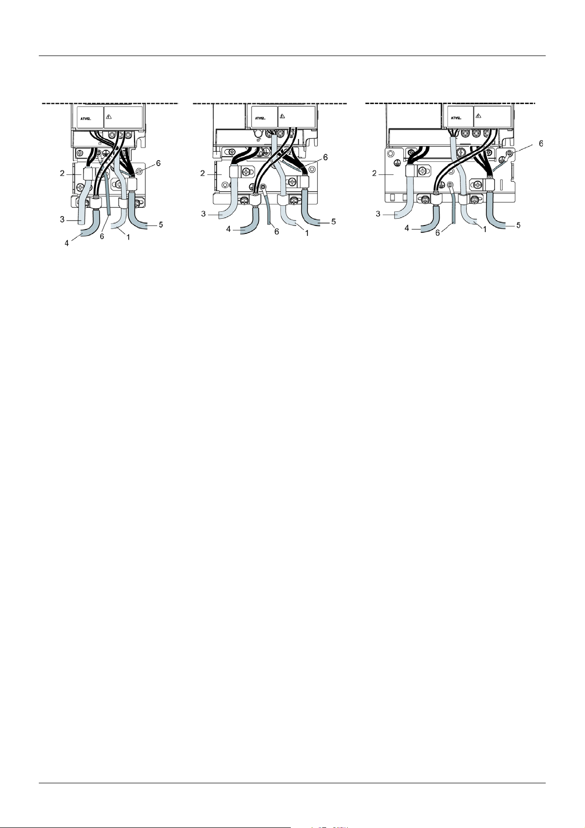
Wiring
1. Non-shielded wires for the output of the status relay contacts.
2. Sheet steel grounded casing not supplied with the drive, to be mounted as indicated on the diagram.
3. PA and PC terminals, to the braking module DC bus
4. Shielded cable for connecting the control/signalling wiring.
For applications requiring several conductors, use small cross-sections (0.5 mm
2
, 20 AWG).
The shielding must be connected to ground at both ends. The shielding must be continuous and intermediate terminals must be in EMC
shielded metal boxes.
5. Shielded cable for motor connection with shielding connected to ground at both ends.
This shielding must be continuous, and if there are any intermediate terminals, they must be in an EMC shielded metal box. The motor
cable PE grounding conductor (green-yellow) must be connected to the grounded casing.
6. Grounding conductor, cross-section 10 mm²
(6 AWG) according to IEC 61800-5-1 standard.
7. Power input (non-shielded cable)
Attach and ground the shielding of cables 4 and 5 as close as possible to the drive:
• Expose the shielding.
• Use cable clamps of an appropriate size on the parts from which the shielding has been exposed, to attach them to the casing.
The shielding must be clamped tightly enough to the metal plate to ensure correct contact.
• Types of clamp: stainless steel (delivered with the optional EMC plate).
Installation diagram (example)
BBV28581 07/2018 27
Wiring
Normal
(filter connected)
IT system
(filter disconnected)
EMC conditions for ATV12ppppM2
C1 EMC category is reached if length of shielded cable is 5 m (16.4 ft) maximum and Switching frequency SFr page 59 is 4, 8 or 12 kHz.
C2 EMC category is reached if length of shielded cable is 10 m (32.8 ft) maximum and Switching frequency SFr is 4, 8 or 12 kHz and if
length of shielded cable is 5 m (16.4 ft) maximum for all other values of Switching frequency SFr.
Internal EMC filter on ATV12ppppM2
All ATV12ppppM2 drives have a built-in EMC filter. As a result they exhibit leakage current to ground. If the leakage current creates
compatibility problems with your installation (residual current device or other), then you can reduce the leakage current by opening the IT
jumper as shown below. In this configuration EMC compliance is not guaranteed.
NOTICE
DRIVE LIFETIME REDUCTION
On ATV12ppppM2 ratings, if the filters are disconnected, the drive’s switching frequency must not exceed 4 kHz. Refer to Switching
frequency SFr page 59
Failure to follow these instructions can result in equipment damage.
for adjustment,
28 BBV28581 07/2018

Check list
Read carefully the safety information in the user manual and the catalog. Before starting up the drive, please check the following points
regarding mechanical and electrical installations, then use and run the drive.
For complete documentation, refer to www.schneider-electric.com.
1. Mechanical installation
• Refer to the Mounting and temperature conditions instructions on page 13 for drive mounting types and recommendations on the
ambient temperature.
• Mount the drive vertically as specified, see Mounting and temperature conditions instructions on page 13
• The use of the drive must be in agreement with the environments defined by the standard 60721-3-3 and according to the levels
defined in the catalog.
• Mount the options required for your application, refer to the catalog.
.
2. Electrical installation
• Connect the drive to the ground, see Equipment grounding on page 16.
• Ensure that the input power voltage corresponds to the drive nominal voltage and connect the line supply as shown in General wiring
diagram on page 18
• Ensure you use appropriate input power fuses and circuit breaker, see in the Annex (S1A58684) delivered with the drive.
• Wire the control terminals as required, see Control terminals on page 23
to the EMC compatibility rules on page 26
•The ATV12ppppM2 range integrates an EMC filter. The leakage current can be reduced using the IT jumper as explained in the
paragraph Internal EMC filter on ATV12ppppM2 on page 28
• Ensure that motor connections correspond to the voltage (star, delta).
.
. Separate the power cable and the control cable according
.
.
3. Use and run the drive
• Start the drive and you will see Standard motor frequency bFr page 45 at the first power-on. Check that the frequency defined by
the frequency bFr (the factory setting is 50 Hz) is in accordance with the frequency of the motor, see First power-up on page 34
For the following power-on, you will see rdY on the HMI.
.
• MyMenu (upper part of CONF mode) allows you to configure the drive for most applications (see page 45
• Factory / recall customer parameter set FCS function page 46
allows you to reset the drive with factory settings.
).
BBV28581 07/2018 29
Factory configuration
ATV12ppppM3
3-phase
motor
Source
Drive factory settings
The Altivar 12 is factory-set for the most common operating conditions (motor rating according to drive rating):
• Display: drive ready (rdY) motor stopped or motor frequency reference while running
• Automatic adaptation of the deceleration ramp in the event of overvoltage on braking.
• No automatic restarting after a detected fault is cleared
• Logic inputs:
- LI1: forward (2-wire transitional control)
- LI2, LI3, LI4: no assignment
• Logic output: LO1: no assignment
• Analog input: AI1 (0 to + 5 V) speed reference
• Relay R1: the contact opens in the event of a detected fault (or drive off)
• Analog output AO1: no assignment
Code Description Value
bFr Standard motor frequency 50 Hz
UnS Rated motor voltage 230 V
ACC Acceleration 3 seconds
dEC Deceleration 3 seconds
LSP Low speed 0 Hz
HSP High speed 50 Hz
Ctt Motor control type Standard law
UFr IR compensation 100%
Ith Motor thermal current equal to nominal motor current (value determined by drive rating)
SdC1 Automatic DC injection current 0.7 x nominal drive current, for 0.5 seconds.
SFr Switching frequency 4 kHz
If the above values are compatible with the application, the drive can be used without changing the settings.
Drive factory wiring diagram
R/L1
S/L2
(1) (3)
R1A
T/L3
R1B
ac
R1C
COM
b
AI1
+5V
AO1
page
45
57
64
64
45
89
90
57
58
94
67
59
(1) R1 relay contacts, for remote indication of the drive status.
(2) Internal + 24 V
use the + 24 V
(3) Reference potentiometer SZ1RV1202 (2.2 k
(4) Forward
30 BBV28581 07/2018
LI3
LI4
(2)
+24 V
(4)
LO-
COM
LI1
LI2
U/T1
V/T2
PA / +
PC / -
U1
c. If an external source is used (+ 30 V c maximum), connect the 0 V of the source to the COM terminal, and do not
c terminal on the drive.
W/T3
V1
W1
M
3 a
) or similar (10 kmaximum).
LO+
 Loading...