

Page 1

Altivar 212
Variable speed drives for asynchronous motors
Modbus communication manual
01/2011
S1A53844
www.schneider-electric.com
Page 2

The information provided in this documentation contains general descriptions and/or technical characteristics
of the performance of the products contained herein. This documentation is not intended as a substitute for
and is not to be used for determining suitability or reliability of these products for specific user applications. It
is the duty of any such user or integrator to perform the appropriate and complete risk analysis, evaluation and
testing of the products with respect to the relevant specific application or use thereof. Neither Schneider
Electric nor any of its affiliates or subsidiaries shall be responsible or liable for misuse of the information
contained herein. If you have any suggestions for improvements or amendments or have found errors in this
publication, please notify us.
No part of this document may be reproduced in any form or by any means, electronic or mechanical, including
photocopying, without express written permission of Schneider Electric.
All pertinent state, regional, and local safety regulations must be observed when installing and using this
product. For reasons of safety and to help ensure compliance with documented system data, only the
manufacturer should perform repairs to components.
When devices are used for applications with technical safety requirements, the relevant instructions must be
followed.
Failure to use Schneider Electric software or approved software with our hardware products may result in
injury, harm, or improper operating results.
Failure to observe this information can result in injury or equipment damage.
© 2011 Schneider Electric. All rights reserved.
2 S1A53844 01/2011
Page 3

Table of Contents
Table of Contents
Safety Information . . . . . . . . . . . . . . . . . . . . . . . . . . . . . . . . . . . . . . . . . . . . . . . . . . . . 5
About the Book. . . . . . . . . . . . . . . . . . . . . . . . . . . . . . . . . . . . . . . . . . . . . . . . . . . . . . . 6
Chapter 1 Introduction. . . . . . . . . . . . . . . . . . . . . . . . . . . . . . . . . . . . . . . . . . . . . . . . . . . . . . . . . . . 9
Chapter 2 Hardware setup. . . . . . . . . . . . . . . . . . . . . . . . . . . . . . . . . . . . . . . . . . . . . . . . . . . . . . . 11
Pin out of the Open Style Modbus connector . . . . . . . . . . . . . . . . . . . . . . . . . . . . . . . . 12
Connection via Open Style wiring system . . . . . . . . . . . . . . . . . . . . . . . . . . . . . . . . . . 13
Open Style Reference . . . . . . . . . . . . . . . . . . . . . . . . . . . . . . . . . . . . . . . . . . . . . . . . . 13
Pin out of the RJ45 Modbus connector . . . . . . . . . . . . . . . . . . . . . . . . . . . . . . . . . . . . 13
Connection via RJ45 wiring system . . . . . . . . . . . . . . . . . . . . . . . . . . . . . . . . . . . . . . . 14
RJ45 Reference . . . . . . . . . . . . . . . . . . . . . . . . . . . . . . . . . . . . . . . . . . . . . . . . . . . . . . 14
Protection Against Interference . . . . . . . . . . . . . . . . . . . . . . . . . . . . . . . . . . . . . . . . . . 15
Description of terminals . . . . . . . . . . . . . . . . . . . . . . . . . . . . . . . . . . . . . . . . . . . . . . . . 16
Chapter 3 Configuration . . . . . . . . . . . . . . . . . . . . . . . . . . . . . . . . . . . . . . . . . . . . . . . . . . . . . . . . 19
Configuration of the communication parameters . . . . . . . . . . . . . . . . . . . . . . . . . . . . . 20
Configuration of the control source. . . . . . . . . . . . . . . . . . . . . . . . . . . . . . . . . . . . . . . . 21
Configuration of the indirect blocks . . . . . . . . . . . . . . . . . . . . . . . . . . . . . . . . . . . . . . . 27
Configuration of the communication interruption . . . . . . . . . . . . . . . . . . . . . . . . . . . . . 28
Chapter 4 Modbus services . . . . . . . . . . . . . . . . . . . . . . . . . . . . . . . . . . . . . . . . . . . . . . . . . . . . . 31
Principle of the Modbus protocol . . . . . . . . . . . . . . . . . . . . . . . . . . . . . . . . . . . . . . . . . 32
RTU mode . . . . . . . . . . . . . . . . . . . . . . . . . . . . . . . . . . . . . . . . . . . . . . . . . . . . . . . . . . 32
Modbus functions available . . . . . . . . . . . . . . . . . . . . . . . . . . . . . . . . . . . . . . . . . . . . . 33
Read one word (03) . . . . . . . . . . . . . . . . . . . . . . . . . . . . . . . . . . . . . . . . . . . . . . . . . . . 33
Read indirect block (3) . . . . . . . . . . . . . . . . . . . . . . . . . . . . . . . . . . . . . . . . . . . . . . . . . 34
Write Single Register (6) . . . . . . . . . . . . . . . . . . . . . . . . . . . . . . . . . . . . . . . . . . . . . . . 36
Write multiple registers (16) . . . . . . . . . . . . . . . . . . . . . . . . . . . . . . . . . . . . . . . . . . . . . 37
Write indirect block (16) . . . . . . . . . . . . . . . . . . . . . . . . . . . . . . . . . . . . . . . . . . . . . . . . 38
Read Device Identification (43/14) . . . . . . . . . . . . . . . . . . . . . . . . . . . . . . . . . . . . . . . . 40
Error response . . . . . . . . . . . . . . . . . . . . . . . . . . . . . . . . . . . . . . . . . . . . . . . . . . . . . . . 41
Chapter 5 Parameter list . . . . . . . . . . . . . . . . . . . . . . . . . . . . . . . . . . . . . . . . . . . . . . . . . . . . . . . . 43
Referring to the Altivar 212 programming manual . . . . . . . . . . . . . . . . . . . . . . . . . . . . 44
List of control parameters . . . . . . . . . . . . . . . . . . . . . . . . . . . . . . . . . . . . . . . . . . . . . . . 45
List of monitoring parameters . . . . . . . . . . . . . . . . . . . . . . . . . . . . . . . . . . . . . . . . . . . . 46
Commands . . . . . . . . . . . . . . . . . . . . . . . . . . . . . . . . . . . . . . . . . . . . . . . . . . . . . . . . . . 48
Setpoints. . . . . . . . . . . . . . . . . . . . . . . . . . . . . . . . . . . . . . . . . . . . . . . . . . . . . . . . . . . . 50
Status . . . . . . . . . . . . . . . . . . . . . . . . . . . . . . . . . . . . . . . . . . . . . . . . . . . . . . . . . . . . . . 51
Trip and alarm codes . . . . . . . . . . . . . . . . . . . . . . . . . . . . . . . . . . . . . . . . . . . . . . . . . . 53
Monitoring and control of I/O from communication. . . . . . . . . . . . . . . . . . . . . . . . . . . . 55
Chapter 6 Appendix . . . . . . . . . . . . . . . . . . . . . . . . . . . . . . . . . . . . . . . . . . . . . . . . . . . . . . . . . . . . 61
RS485 standard . . . . . . . . . . . . . . . . . . . . . . . . . . . . . . . . . . . . . . . . . . . . . . . . . . . . . . 62
Modbus 2-wire standard schematic . . . . . . . . . . . . . . . . . . . . . . . . . . . . . . . . . . . . . . . 62
Chapter 7 Migration . . . . . . . . . . . . . . . . . . . . . . . . . . . . . . . . . . . . . . . . . . . . . . . . . . . . . . . . . . . . 63
Migration ATV21 - ATV212. . . . . . . . . . . . . . . . . . . . . . . . . . . . . . . . . . . . . . . . . . . . . . 64
S1A53844 01/2011 3
Page 4

Table of Contents
4 S1A53844 01/2011
Page 5

§
Safety Information
Important Information
NOTICE
Read these instructions carefully, and look at the equipment to become familiar with the device before trying
to install, operate, or maintain it. The following special messages may appear throughout this documentation
or on the equipment to warn of potential hazards or to call attention to information that clarifies or simplifies a
procedure.
The addition of this symbol to a Danger or Warning safety label indicates that an electrical hazard
exists, which will result in personal injury if the instructions are not followed.
This is the safety alert symbol. It is used to alert you to potential personal injury hazards. Obey all
safety message that follow this symbol to avoid possible injury or death.
PLEASE NOTE
DANGER
DANGER indicates an imminently hazardous situation, which, if not avoided, will result in death or serious
injury.
WARNING
WARNING indicates a potentially hazardous situation, which, if not avoided, can result in death, serious
injury or equipment damage.
CAUTION
CAUTION indicates a potentially hazardous situation, which, if not avoided, can result in injury or equipment
damage.
CAUTION
CAUTION, used without the safety alert symbol, indicates a potentially hazardous situation which, if not
avoided, can result in equipment damage.
The word “drive” as used in this manual refers to the controller portion of the adjustable speed drive as defined
by NEC.
Electrical equipment should be installed, operated, serviced, and maintained only by qualified personnel. No
responsibility is assumed by Schneider Electric for any consequences arising out of the use of this material.
S1A53844 01/2011 5
Page 6

At a Glance
Document Scope
Validity Note
Related Documents
About the Book
The purpose of this document is to show you how to configure the Altivar 212 to use Modbus for monitoring
and control.
NOTE: Read and understand this document and all related documents (see below) before installing,
operating, or maintaining your ATV212.
This documentation is valid for the Altivar 212 Modbus fieldbus.
Title of Documentation Reference Number
ATV212 Quick Start S1A53825
ATV212 Installation manual S1A53832
ATV212 Programming manual S1A53838
ATV212 BACnet manual S1A53845
ATV212 Metasys N2 manual S1A53846
ATV212 Apogée FLN P1 manual S1A53847
ATV212 LonWorks manual S1A53848
ATV212 other option manuals: see www.schneider-electric.com
You can download the latest versions of these technical publications and other technical information from our
website at www.schneider-electric.com.
Product Related Information
UNINTENDED EQUIPMENT OPERATION
• Read and understand this manual before installing or operating the Altivar 212 drive.
• Any changes made to the parameter settings must be performed by qualified personnel.
Failure to follow these instructions will result in death or serious injury.
DANGER
6 S1A53844 01/2011
Page 7

DANGER
HAZARD OF ELECTRIC SHOCK, EXPLOSION OR ARC FLASH
• Read and understand this manual before installing or operating the drive. Installation, adjustment, repair,
and maintenance must be performed by qualified personnel.
• The user is responsible for compliance with all international and national electrical code requirements with
respect to grounding of all equipment.
• Many parts of this drive, including the printed circuit boards, operate at the line voltage. DO NOT TOUCH.
Use only electrically insulated tools.
• DO NOT touch unshielded components or terminal strip screw connections with voltage present.
• DO NOT short across terminals PA/+ and PC/– or across the DC bus capacitors.
• Before servicing the drive:
- Disconnect all power, including external control power that may be present.
- Place a “DO NOT TURN ON” label on all power disconnects.
- Lock all power disconnects in the open position.
- WAIT 15 MINUTES to allow the DC bus capacitors to discharge.
- Measure the voltage of the DC bus between the PA/+ and PC/– terminals to ensure that the voltage is
less than 42 Vdc.
- If the DC bus capacitors do not discharge completely, contact your local Schneider Electric
representative. Do not repair or operate the drive
• Install and close all covers before applying power or starting and stopping the drive.
Failure to follow these instructions will result in death or serious injury.
WARNING
DAMAGE DRIVE EQUIPMENT
Do not operate or install any drive or drive accessory that appears damaged.
Failure to follow these instructions can result in death, serious injury, or equipment damage.
WARNING
LOSS OF CONTROL
• The designer of any control scheme must consider the potential failure modes of control paths and, for
certain critical control functions, provide a means to achieve a safe state during and after a path failure.
Examples of critical control functions are emergency stop and overtravel stop.
• Separate or redundant control paths must be provided for critical control functions.
• System control paths may include communication links. Consideration must be given to the implications
of unanticipated transmission delays or failures of the link (1).
Failure to follow these instructions can result in death, serious injury, or equipment damage.
(1) For additional information, refer to NEMA ICS 1.1 (latest edition), “Safety Guidelines for the Application, Installation, and
Maintenance of Solid State Control” and to NEMA ICS 7.1 (latest edition), “Safety Standards for Construction and Guide
for Selection, Installation and Operation of Adjustable-Speed Drive Systems.”
S1A53844 01/2011 7
Page 8

8 S1A53844 01/2011
Page 9

Introduction
Introduction
1
Data exchanges give access to all Altivar 212 functions:
• Control (start, stop, reset, setpoint),
• Monitoring (status, current, voltage, thermal state...),
• Diagnostics (alarms),
• Settings,
• Configuration.
The communication port has an RJ45 and an open style connector for the connection to the network. At the
physical layer, it supports 2-wire RS485 and transmission speed at 9600 or 19200 bps.
4 Modbus functions are available:
• 3 (16#03) Read Holding Registers
• 6 (16#06) Write Single Register
• 16 (16#10) Write Multiple Registers
• 43/14 (16#2B/0E) Read Device Identification
Function 3 has a restricted implementation:
• with length 1 it permits to read any parameter of the drive, one by one, see page 33.
• with lengths 1 to 5 it permits to read a particular block of 1 to 5 indirect parameters. These 5 parameters
can be configured through the operation panel to relevant monitoring parameters, see page 34.
Function 16 has a restricted implementation:
• with length 1 it permits to write any writable parameter of the drive, one by one, see page 37.
• with length 1 to 2 it permits to write a particular block of 1 to 2 indirect parameters. These 2 parameters can
be configured through the operation panel to relevant control parameters, see page 38.
S1A53844 01/2011 9
Page 10

Introduction
10 S1A53844 01/2011
Page 11

Hardware setup
Hardware setup
What's in this Chapter?
This chapter contains the following topics:
Pin out of the Open Style Modbus connector 12
Connection via Open Style wiring system 13
Open Style Reference 13
Pin out of the RJ45 Modbus connector 13
Connection via RJ45 wiring system 14
RJ45 Reference 14
Protection Against Interference 15
Description of terminals 16
2
Topic Page
S1A53844 01/2011 11
Page 12
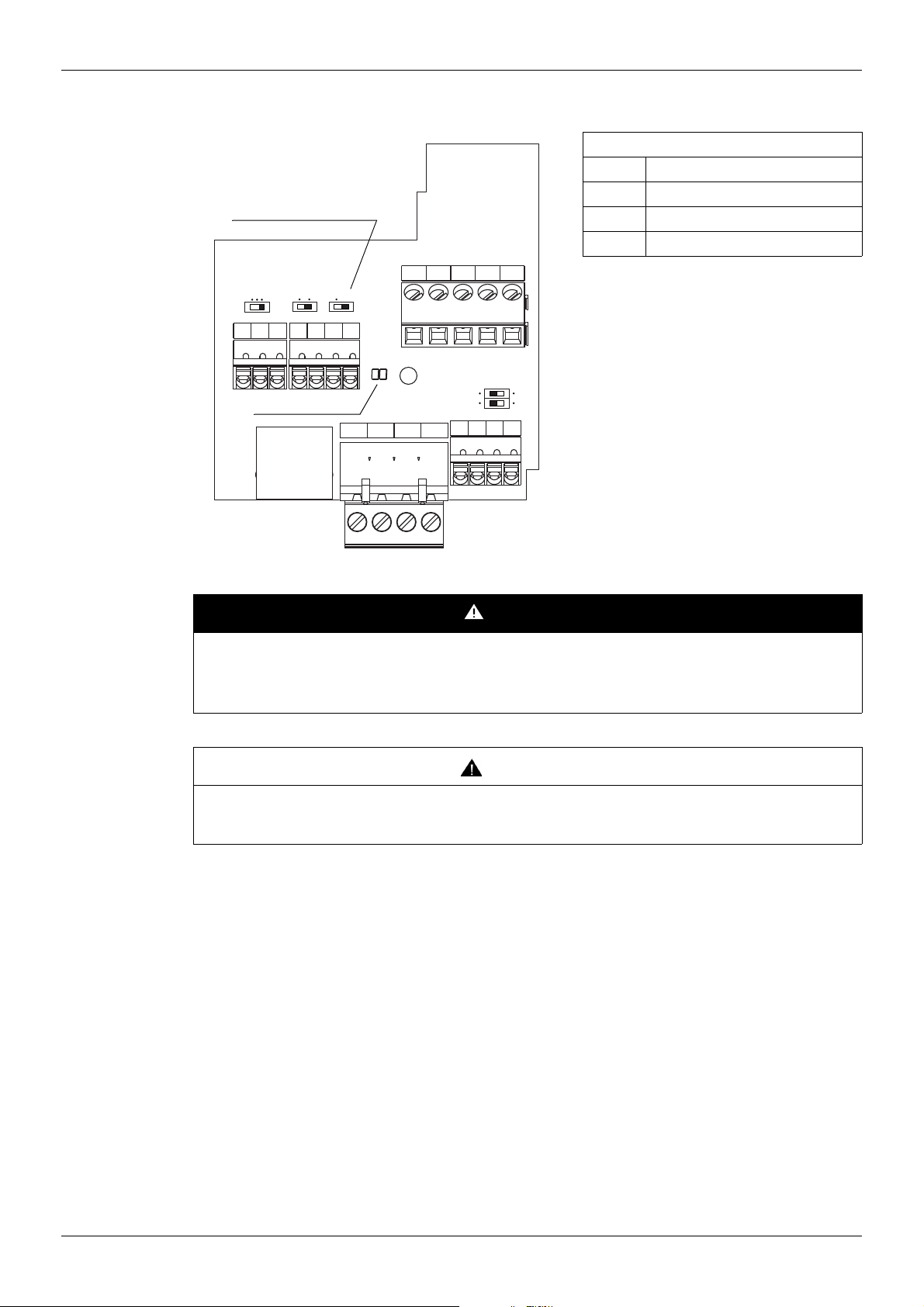
Pin out of the Open Style Modbus connector
Open Style Connector
RJ45
Diagnostic DELs
Line termination switch
PLC FM
Sink
SW102
FR
Source
SW101
RES PLC P24
IU
Term
SW103
CC FM
BAGNDSCR
FLA
FLB FLC RYA RYC
VIA U
VIB U
SW100
PP CCVIA VIB
I
PTC
Hardware setup
Open Style Connector (screwcage plug style)
B +
A –
GND Common
SCR Shield
Note: It is possible to connect two wires
inside one cage in order to be compliant to
daisy chain requirements.
Cross section:
0.2 - 2.5 mm² / AWG 24-12
Tightening torque:
0.5-0.6 Nm / 4.4-5.3 lb/In.
DANGER
UNINTENDED EQUIPMENT OPERATION
• Modify only the setting of the switches when the product is switched off.
• Do not change the setting of the SW102 unless your system is wired for SINK logic.
Failure to follow these instructions will result in death or serious injury.
CAUTION
RISK OF BODY INJURY
Use a screwdriver to change the position of the switches.
Failure to follow these instructions will result in death or serious injury.
12 S1A53844 01/2011
Page 13
Hardware setup
ATV 212
2
1
2
Master
1 Modbus cable depending on the type of master
2 RS 485 double shielded twisted pair cable
8........................1
Connection via Open Style wiring system
Open Style Reference
Modbus serial link connection is carried out using RS 485 double shielded twisted pair cables, supplied without
connector (reference: TSX CSA 100). Maximum length is 100 m (328 ft). The ATV212 drive includes a line
termination as standard. Set switch SW103 to Term to connect the internal 120 Ω termination resistor.
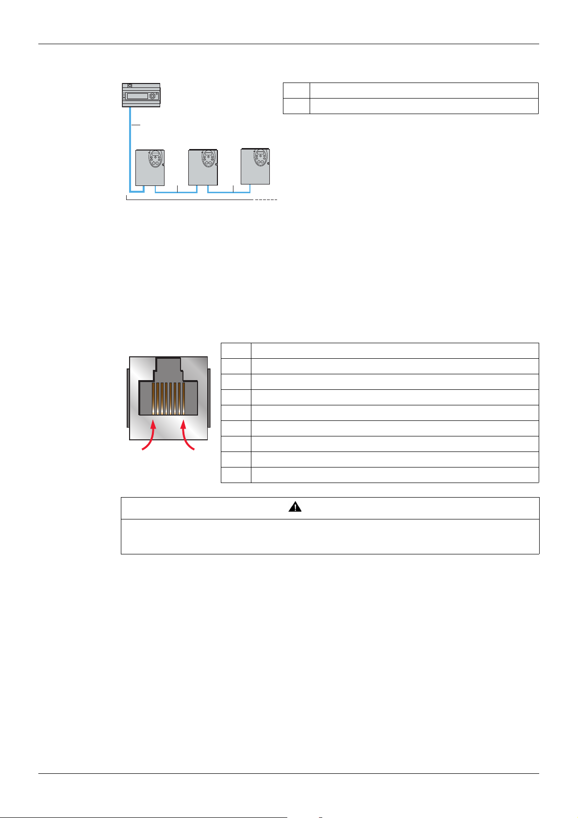
Pin out of the RJ45 Modbus connector
View from underneath
The following table describes the pin out of the ATV212 RJ45 connector.
Pin Signal
1 Not connected
2 Common (common of the signal and power supply)
3 Not connected
4 D1 (Modbus name) or B (EIA / TIA485 name)
5 D0 (Modbus name) or A (EIA / TIA485 name)
6 Not connected
7 VP, 10 Vdc (supply for RS232/RS485 converter or graphic display option)
8 Common (common of the signal and power supply)
CAUTION
RISK OF DAMAGE TO THE DRIVE
Use wiring cables or taps that connect only signals D0, D1 and common.
Failure to follow this instruction can result in injury or equipment damage.
S1A53844 01/2011 13
Page 14

Connection via RJ45 wiring system
Master
1 Modbus cable depending on the type of master
2 Modbus splitter box
3 Modbus drop cables
4 Modbus T-junction box
5 Line terminators
Hardware setup
1
ATV 212
3
2
5
33
34 4 5
33
Description
RJ45 is factory set to connect the graphic display option.
Use the open style connector to connect the drive to Modbus fieldbus.
Using RJ45 to connect Modbus fieldbus is still possible but requires to modify parameter [Com channel choice]
F807 value. Set F807 to 0 [RJ45].
RJ45 Reference
Connection accessories
Description Reference
Modbus splitter block 10 RJ45 connectors and 1 screw terminal LU9 GC3
Modbus T-junction boxes With integrated cable (0.3 m) VW3 A8 306 TF03
With integrated cable (1 m) VW3 A8 306 TF10
Line
terminators
For RJ45 connector R = 120 Ω, C = 1 nF VW3 A8 306 RC
R = 150 Ω VW3A8306R
Connecting cables
Description Length
m
Cables for
Modbus bus
RS 485 double
shielded twisted pair
cables
Type of master Master interface Modbus connection accessories for RJ45 wiring system
Twido PLC
TSX Premium PLC TSX SCY 11601 or
3 1 RJ45 connector and 1 stripped end VW3 A8 306 D30
0.3 2 RJ45 connectors VW3 A8 306 R03
1 2 RJ45 connectors VW3 A8 306 R10
3 2 RJ45 connectors VW3 A8 306 R30
100 Supplied without connector TSX CSA 100
200 Supplied without connector TSX CSA 200
500 Supplied without connector TSX CSA 500
Adaptor or mini-DIN RS485
interface module
Adaptor or screw terminal
RS485 interface module
TSX SCY 21601 module
(SUB-D 25 socket)
PCMCIA card (TSX SCP114) Stripped cable TSX SCP CM 4030
Connectors Reference
Description Reference
3 m cable fitted with a mini-DIN connector and an RJ45
connector
3 m cable fitted with an RJ45 connector and stripped at the other
end
Cable fitted with a SUB-D 25 connector and stripped at the other
end (for connection to the screw terminals of the LU9GC3 splitter
block)
TWD XCA RJ030
VW3 A8 306 D30
TSX SCY CM 6030
14 S1A53844 01/2011
Page 15

Hardware setup
Ethernet bridge
(TSX ETG 100)
Serial port PC Male SUB-D 9 RS232 serial
Screw terminal RS485 3 m cable fitted with an RJ45 connector and stripped at the other
port PC
Protection Against Interference
•
Use the Schneider Electric cable with 2 pairs of shielded twisted conductors (reference: TSXCSA100,
TSXCSA200, TSXCSA500).
• Keep the Modbus cable separated from the power cables (30 cm (11.8 in.) minimum).
• Make any crossovers of the Modbus cable and the power cables at right-angles, if necessary.
For more information, please refer to the TSX DG KBL E manual: “Electromagnetic compatibility of industrial
networks and fieldbuses”.
end
RS232/RS485 converter and
3 m cable fitted with an RJ45 connector and stripped at the other
end (for connection to the screw terminals of the LU9GC3 splitter
block)
VW3 A8 306 D30
TSX SCA 72 and
VW3 A8 306 D30
S1A53844 01/2011 15
Page 16
Description of terminals
1n F
650 Ω
650 Ω
120 Ω
1n F
120 Ω
5 V
0 V
G
R
G
R
G
R
D1
Common
D0
SINK
SOURCE
PP
+24V
(1)
RYA
RYC
FLA
FLB
FLC
Hardware setup
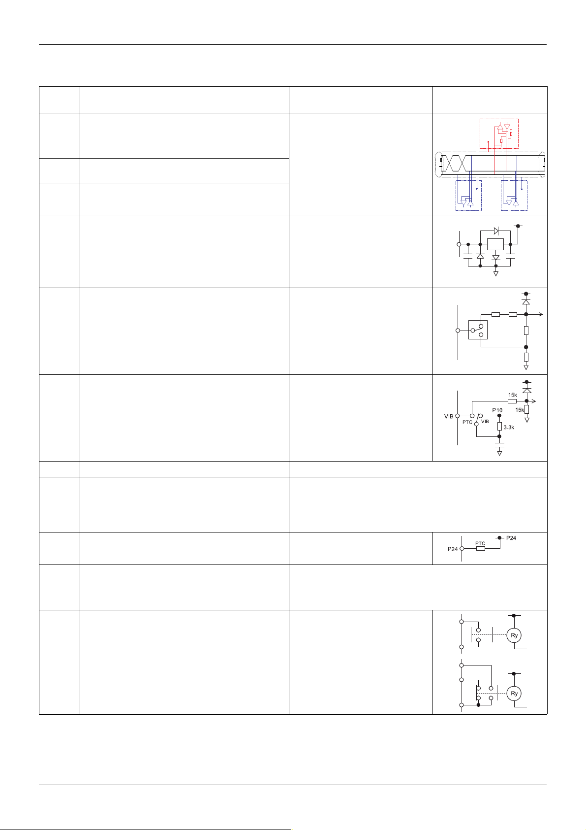
Terminal
symbol
Function Electrical specifications Internal circuits
Multifunctional programmable logic input.
F
It has forward rotation function in default setting.
ON: forward rotation drive
OFF: slowdown and stop
R
RES
Multifunctional programmable logic input.
It has Preset speed command input 1 in default setting.
Multifunctional programmable logic input.
It has Fault Reset in default setting
PP Voltage supply for reference potentiometer.
Switch-configurable voltage or current analog input using
SW100.
VIA
It has speed setpoint function in the default setting. (0 to 50
Hz frequency with 0 to 10 Vdc in voltage or with 0 to 20 mA
in current input). In addition,This analog input is also
configurable as a logic input.
Input for voltage-free contact
24 Vdc, 5 mA or less.
SINK/SOURCE can be selected with
SW102.
Voltage: 10 Vdc
Max current: 10 mA
Protected against short circuits.
Voltage: 10 Vdc
Internal impedance: 30 kΩ
Current: 0 - 20 mA
VIA
U
15k
I
300k
15k
250k
Multifunction programmable analog input.
It has speed setpoint function in the default setting
VIB
(0 to 50 Hz frequency with 0 to 10 Vdc input). In addition,
this terminal can be used as PTC (2) input by setting switch
Voltage: 10 Vdc
Internal impedance: 30 kΩ
SW100 and the parameters [Mot PTC selection] F645
and [PTC resistor value] F646.
CC Control circuit equipotential terminal -
This terminal is only active when the switch (SINKSOURCE) is on PLC position. It allow to manage external
PLC
sink or source with static outputs. PLC shall be connected
Max. voltage: 50 Vdc
to 0V (CC terminal) or +24V according to the type of
outputs
P24 24 Vdc power supply output Voltage: 24 Vdc, 50 mA
Voltage analog output: 0...10 Vdc
FM
Switch-configurable voltage or current analog output using
SW101.
Minimum load impedance: 470 Ω
Current analog output: 0...20 mA
Maximum load impedance: 550 Ω
FLA
FLB
FLC
RYA
RYC
Multifunctional programmable relay contact outputs.
Default setting is set to detect the activation of the drive
protection function.
Contact across FLA-FLC is closed and FLB-FLC is open
during normal operation. RYA -RYC is open.
Voltage: 30 Vdc, 0.5 A
250 Vac, 1A
(cos
ϕ = 1)
Voltage: 250 Vac, 0.5A
(cos
ϕ = 0.4)
(2)
(1) Voltage conversion
(2) PTC (Positive Temperature Coefficient): Resettable thermal fuse resistor for over current protection.
16 S1A53844 01/2011
Page 17

Hardware setup
B
A
BACnet open style connector
GND
RS485 transmission data, reception
data.
47k
4.7k
B
A
4.7k
47k
SCR
BACnet communication shield terminal.
This terminal is not connected to other circuits in the board.
Ground this terminal in a location separated from the ground of the power line.
GND
SCR
TERM
120
SW103
S1A53844 01/2011 17
Page 18

Hardware setup
18 S1A53844 01/2011
Page 19

Configuration
Configuration
What's in this Chapter?
This chapter contains the following topics:
Configuration of the communication parameters 20
Configuration of the control source 21
Configuration of the indirect blocks 27
Configuration of the communication interruption 28
The settings of communication-related parameters can be changed from the operation panel or from Modbus
(PLC, computer or controller) or from graphic display option.
3
Topic Page
Note that there are two types of parameters: parameters whose settings take effect immediately after the
setting and parameters whose settings do not take effect until the drive is turned back on or reset. In the table
below, these 2 types are mentioned in the column "valid" by "After setting" and "After power cycle".
S1A53844 01/2011 19
Page 20

Configuration of the communication parameters
Access to the parameters
All parameters are accessible in the [COMMUNICATION MENU] COM submenu of [PROGRAMMING
MENU] Programming mode.
UNINTENDED EQUIPMENT OPERATION
Refer to «Serial communication parameters» in the Altivar 212 Programming manual, for more information
on how to set these serial communication parameters.
Failure to follow these instructions will result in death or serious injury.
Description
Parameters Modbus
[Mdb RJ45 baud] (F800)
Communication Modbus RJ45 Baud rate
[Mdb RJ45 parity] (F801)
Communication Modbus RJ45 Parity
[Modbus address] (F802)
This address is used whatever the port used.
[Com. time out] (F803)
Communication time out
[Com channel choice] (F807)
Communication channel choice
[Mdb network baud] (F820)
Modbus network baud rate
[Mdb network parity] (F821)
Modbus network parity
[Network protocol] (F829)
Communication Network protocol selection
DANGER
Adjustment range Default
address
2048
16#800
2049
16#801
2050
16#802
2051
16#803
2055
16#807
2080
16#820
2081
16#821
2089
16#829
0 [9600 bps]
1 [19200 bps]
0 [No] (No parity)
1 [Even] (Even parity)
2 [Odd] (Odd parity)
0 ... 247 1 Setting
0 or
1 ... 100 seconds
0 [RJ45]
1 [Open style]
0 [9600 bps]
1 [19200 bps]
[No] (No parity)
0
1 [Even] (Even parity)
2 [Odd] (Odd parity)
1 ... 5
1 [Mdb RTU]
Configuration
Valid
setting
after
1 Power cycle
1 Power cycle
3 Setting
1 Setting
1 Power cycle
1 Power cycle
1 Power cycle
Notes:
• Baud rate and parity bit should be uniform inside the same network.
• Modbus address should not be duplicate inside the same network.
• Stop bit isn't configurable. ATV212 Tx is 2 stop bit, Rx is 1 or 2 stop bits. This permits a good comunication
with Master in 1 and 2 stop bits.
• F800 and F801 parameters are used to define the baudrate and parity of RJ45 port.
• F820 and F821 parameters are used to define the baudrate and parity of Open style connector port.
• F802 and F803 parameters are used to define the modbus address and communication time out for
both ports (RJ45 et Open style connector). Set F802 between 1 to 247 (address 0 is not active).
• F807 parameter enables to select the communication command channel: RJ45 or Open style connector.
The port not set as the communication command channel may be used for monitoring purposes to check
that the setting change on F807 was effectively taken into account.
20 S1A53844 01/2011
Page 21

Configuration
0
1
2
1
2
3
4
5
4
0
1
LOC
REM
Commands CMOd
Operation panel
Modbus
commands
Terminals
Operation panel
Modbus
setpoint
UP/DOWN
Bit 15 of
command word FA00
Serial com. command priority bit
ON
Operation
panel
Commands
Setpoint
Modbus commands
Modbus setpoint
Setpoint
FMOd
OFF
ON
OFF
Operation
panel
VIB
VIA
Bit 14 of
command word FA00
Serial com. setpoint priority bit
REM
LOC
REM
LOC
F807
Communication
RJ45 channel: Modbus
Network channel:
Paremeter F829
Configuration of the control source
The Altivar 212 can receive commands and setpoint from the Modbus network or from the terminals (F, R,
RES, VIA, VIB). In the default configuration, both commands and setpoint come from the terminals.
The LOC/REM key of the operation panel is available to switch the control to the operation panel. The inputs
F, R or RES can be configured to switch the control from the Modbus network to the terminals.
Different usual possibilities are described in the chapters below:
• Control from the Modbus network,
• Control from the terminals, monitoring from the Modbus network,
• Control from the Modbus network or the terminals, switched via Modbus,
• Command from the Modbus network, setpoint from the Modbus network or the terminals switched to by a
logic input.
Refer to these examples.
Control by the Modbus network
The commands and the setpoint come from the Modbus network. The signals wired on the terminals are
ignored. The LOC/REM key is valid.
Below is the list of parameters that must be configured.
Access to the parameters
Parameters Location
[Command mode sel] (CMOd)
[Frequency mode sel] (FMOd)
Other parameters [COMMUNICATION MENU] COM submenu of
[PROGRAMMING MENU] Programming mode
[PROGRAMMING MENU] Programming mode.
Description
Parameters Modbus
address
[Command mode sel] (CMOd)
Remote mode start/stop control
[Frequency mode sel] (FMOd)
Remote mode primary speed reference source
[Com channel choice] (F807)
Communication channel selection
[Network protocol] (F829)
Communication Network protocol selection
3
16#3
4
16#4
2055
16#807
2089
16#829
Setting Default
setting
2 [Communication]
Serial communication
4 [Serial com ref.]
Serial communication
0 [RJ45] or
1 [Open style]
1 [Modbus-RTU protocol] 1 Power
0 Setting
1 Setting
1 Setting
S1A53844 01/2011 21
Valid
after
cycle
Page 22

Control by the terminals, monitoring by the Modbus network
0
1
2
2
3
454
0
1
1
LOC
REM
Commands CMOd
Operation panel
Modbus
commands
Terminals
Operation panel
Modbus
setpoint
UP/DOWN
Bit 15 of
command word FA00
Serial com. command priority bit
ON
Operation
panel
Commands
Setpoint
Modbus commands
Modbus setpoint
Setpoint
FMOd
OFF
ON
OFF
Operation
panel
VIB
VIA
Bit 14 of
command word FA00
Serial com. setpoint priority bit
REM
LOC
REM
LOC
F807
Communication
RJ45 channel: Modbus
Network channel:
Paremeter F829
The commands and the setpoint come from the terminals.
The Altivar 212 is monitored via the Modbus network.
The LOC/REM key is valid.
Below is the list of parameters that must be configured.
Access to the parameters
Parameters Location
[Command mode sel] (CMOd)
[Frequency mode sel] (FMOd)
[Com channel choice] (F807) [COMMUNICATION MENU] COM submenu of
Description
Configuration
[PROGRAMMING MENU] Programming mode
[PROGRAMMING MENU] Programming mode.
Parameters Modbus
address
[Command mode sel] (CMOd)
Remote mode start/stop control
[Frequency mode sel] (FMOd)
Remote mode primary speed reference source
[Com channel choice] (F807)
Communication channel selection
3
16#3
4
16#4
2055
16#807
Setting Default
setting
0 [Logic inputs]
Control terminal logic inputs
1 [Ref source VIA]
The source of the drive’s
speed reference is VIA.
0 [RJ45] or
1 [Open style]
0 Setting
1 Setting
1 Setting
Valid
after
22 S1A53844 01/2011
Page 23

Configuration
Commands CMOd
Terminals
Modbus commands
Bit 15 of
command word FA00
Serial com. command
priority bit
Operation
panel
Commands
Setpoint
Modbus setpoint
Bit 14 of
command word FA00
Serial com. setpoint
priority bit
Setpoint FMOd
Operation
panel
Operation panel
Modbus
commands
Terminals
Operation panel
Modbus setpoint
UP/DOWN
ON
OFF
ON
OFF
VIB
VIA
REM
LOC
REM
LOC
F807
Communication
RJ45 channel: Modbus
Network channel:
Paremeter F829
Control by the Modbus network or the terminals, switched via Modbus
The commands come from the terminals if bit 15 of the command word [Command from serial communication]
(FA00) is "OFF" (value 0).
The commands come from the Modbus network if bit 15 of the command word (FA00) is "enabled" (value 1).
The setpoint comes from the terminals if bit 14 of the command word (FA00) is "OFF" (value 0).
The setpoint comes from the Modbus network if bit 14 of the command word (FA00) is "enabled" (value 1).
The LOC/REM key is valid.
Below is the list of parameters that must be configured.
Access to the parameters
Parameters Location
[Command mode sel] (CMOd)
[Frequency mode sel] (FMOd)
[Com channel choice] (F807) [COMMUNICATION MENU] COM submenu of
[PROGRAMMING MENU] Programming mode
[PROGRAMMING MENU] Programming mode.
Description
S1A53844 01/2011 23
Parameters Modbus
[Command mode sel] (CMOd)
Remote mode start/stop control
[Frequency mode sel] (FMOd)
Remote mode primary speed reference source
[Com channel choice] (F807)
Selection of Communication channel: via RJ45 or
Open style connector port
0
1
2
1
2
3
454
0
1
address
3
16#3
4
16#4
2055
16#807
Setting Default
0 [Logic inputs]
Control terminal logic inputs
1 [Ref source VIA]
The source of the drive’s
speed reference is VIA.
0 [RJ45] or
1 [Open style]
setting
0 Setting
1 Setting
1 Setting
LOC
REM
Valid
after
Page 24

Control by the Modbus network or the terminals switched to by a logic input
OFF
Operation
panel
Commands
Setpoint
Modbus
commands
Modbus
setpoint
ON
OFF
ON
REM
LOC
REM
LOC
Operation
panel
ON
OFF
ON
OFF
Commands CMOd
Terminals
Bit 15 of
command word FA00
Serial com. command
priority bit
Bit 14 of
command word FA00
Serial com. setpoint
priority bit
Setpoint FMOd
Operation panel
Modbus commands
Operation panel
Modbus setpoint
UP/DOWN
VIB
VIA
Logic input R
[LI R selection]
F112 set to
48 [Forced local]
The commands and the setpoint come from the Modbus network if logic input R is OFF.
The commands and the setpoint come from the terminals if logic input R is ON.
The function 48 [Forced local] is assigned to the logic input R, F112 = 48.
The LOC/REM key is valid.
Below is the list of parameters that must be configured.
Access to the parameters
Parameters Location
[Command mode sel] (CMOd)
[Frequency mode sel] (FMOd)
[Com channel choice] (F112)
[Com channel choice] (F807) [COMMUNICATION MENU] COM submenu
[PROGRAMMING MENU] Programming mode
[I/O MENU] IO submenu of [PROGRAMMING MENU] Programming mode.
of [PROGRAMMING MENU] Programming mode.
Description
Configuration
Parameters Modbus
address
[Command mode sel] (CMOd)
Remote mode start/stop control
[Frequency mode sel] (FMOd)
Remote mode primary speed reference source
[LI R selection] (F112)
R logic input function
[Com channel choice] (F807)
Selection of Communication channel: via RJ45 or
Open style connector port
3
16#3
4
16#4
274
16#112
2055
16#807
0
1
2
Setting Default
setting
0 [Logic inputs]
Control terminal logic inputs
1 [Ref source VIA]
The source of the drive’s speed
reference is VIA.
48 [Forced local]: configured to
Forced switching from remote to
local control
0 [RJ45] or
1 [Open style]
0 Setting
1 Setting
6 Setting
1 Setting
LOC
REM
Valid
after
1
2
3
4
5
24 S1A53844 01/2011
Page 25

Configuration
Command by the Modbus network, setpoint by the Modbus network or the terminals switched to by a logic input
The commands come from the Modbus network.
The setpoint comes from the Modbus network if logic input R is OFF.
The setpoint comes from the terminals if logic input R is ON.
The function 38 [Frequency source] is assigned to the logic input R, F112 = 38.
The LOC/REM key is valid.
Below is the list of parameters that must be configured.
Access to the parameters
Parameters Location
[Command mode sel] (CMOd)
[Frequency mode sel] (FMOd)
[Com channel choice] (F112)
[Remote spd ref 2] (F207)
[Com channel choice] (F807) [COMMUNICATION MENU] COM submenu
[PROGRAMMING MENU] Programming mode
[I/O MENU] IO submenu of [PROGRAMMING MENU]
Programming mode.
[EXTENDED MENU] F--- submenu of [PROGRAMMING
MENU] Programming mode.
of [PROGRAMMING MENU] Programming mode.
Description
Parameters Modbus
address
[Command mode sel] (CMOd)
Remote mode start/stop control
[Frequency mode sel] (FMOd)
Remote mode primary speed reference source
[LI R selection] (F112)
R logic input function
[Remote spd ref 2] (F207)
Remote mode secondary speed reference source
that may override the source selected by FMOd
[Com channel choice] (F807)
Selection of Communication channel: via RJ45 or
Open style connector port
3
16#3
4
16#4
274
16#112
519
16#207
2055
16#807
Setting Default
setting
2 [Communication]
Serial communication
4 [Serial com ref.]
Serial communication
38 [Frequency source]
Configured to Frequency reference
source switching
1 [VIA]: VIA 2 Setting
0 [RJ45] or
1 [Open style]
Valid
after
0 Setting
1 Setting
6 Setting
1 Setting
S1A53844 01/2011 25
Page 26

Configuration
0
1
2
1
2
3
4
5
1
2
3
4
5
LOC
REM
0
1
Commands CMOd
Operation panel
Terminals
UP/DOWN
Setpoint FMOd
VIB
VIA
Operation panel
UP/DOWN
VIB
VIA
Setpoint F207
Operation
panel
Operation
panel
OFF
ON
OFF
ON
Logic input R
[LI R selection]
F112 set to
38 [Frequency source] or
F200 [Auto/man speed ref]
REM
LOC
REM
LOC
Command
Setpoint
F807 [Com channel choice]
RJ45 channel: Modbus
Network channel:
parameter
F829 [Network protocol]
Bit 15 of
command word FA00
Serial com. command
priority bit
Bit 14 of
command word FA00
Serial com. setpoint
priority bit
OFF
ON
Modbus
commands
Modbus
setpoint
Modbus
setpoint
Modbus
commands
Modbus
setpoint
Modbus
setpoint
ON
OFF
Bit 14 of
command word FA00
Serial com. setpoint
priority bit
Commands CMOd
Modbus
commands
Bit 15 of
command word FA00
Serial com. command
priority bit
Operation
panel
Commands
Setpoint
Modbus
setpoint
Bit 14 of
command word FA00
Serial com. setpoint
priority bit
Logic input F, R or RES
F111 ... F113
configured to 48
[Forced local]
Logic input F, R or RES
F111 ... F113
configured to38
[Frequency source]
Operation
panel
Modbus
commands
Operation
panel
Modbus
setpoint
VIB
UP/DOWN
Setpoint FMOd
Setpoint F207
Terminals
VIA
Operation
panel
Modbus
setpoint
VIB
UP/DOWN
VIA
Operation
panel
Modbus
setpoint
Bit 14 of
command word FA00
Serial com. setpoint
priority bit
OFF
ON
REM
LOC
REM
LOC
REM
LOC
REM
LOC
ON
OFF
ON
OFF
ON
OFF
F807 [Com channel choice]
RJ45 channel: Modbus
Network channel:
parameter
F829 [Network protocol]
Complete control diagram
26 S1A53844 01/2011
0
1
2
1
2
3
4
5
1
2
3
4
5
0
1
LOC
REM
Page 27

Configuration
Configuration of the indirect blocks
Configuration
These parameters configure the Modbus functions "Read indirect block (3)", page 34 and "Write indirect block
(16)", page 38.
Access to the parameters
All parameters are accessible in the [COMMUNICATION MENU] COM submenu of [PROGRAMMING
MENU] Programming mode.
Description
Parameters Modbus
address
[Block write data 1] (F870) 2160
16#870
[Block write data 2] (F871) 2161
16#871
[Block read data 1] (F875) 2165
16#875
[Block read data 2]
[Block read data 3] (F877) 2167
[Block read data 4] (F878) 2168
[Block read data 5] (F879) 2169
(F876) 2166
16#876
16#877
16#878
16#879
Adjustment range Default
setting
0 [No select]: No selection
1 [Command word 1]
2 [Command word 2]
3 [Frequency Setpoint]
4 [Relay command]: Ouput data on the terminal board
5 [FM command]: Analog output for communication
6 [Speed Setpoint]
0 [No select]: No selection
1 [Status info]
2 [Freq. out]: Output frequency
3 [Motor current]: Ouput current
4 [Ouput volt]: Ouput voltage
5 [Alarm info]: Alarm information
6 [PID feedback value]
7 [Input term. mon]: Input terminal board monitor
8 [Out term. mon]: Output terminal board monitor
9 [VIA monitor]: VIA terminal board monitor
10 [VIB monitor]: VIB terminal board monitor
11 [Mot speed mon.]: Ouput motor speed monitor
0
0
Valid
after
Power
cycle
Power
cycle
S1A53844 01/2011 27
Page 28

Configuration of the communication interruption
ON:
OFF:
OpenStyle Tx
OpenStyle Rx
RJ45 Tx
RJ45 Rx
Mdb com stat
RJ45 B - A - COM
Rx Tx Rx Tx
Rem Loc/Rem
RJ45:
Mb activity on RJ45 port
When Rx and/or Tx are
displayed in this row
their state is inactive
B-A-COM:
Mb activity
on OpenStyle port
Switch between local to remote
mode using the F4 button on the
display terminal
Mdb com stat
RJ45 B - A - COM
Tx Rx Tx
Rx
Rem Loc/Rem
Mdb com stat
RJ45 B - A - COM
Rx Rx Tx
Tx
Rem Loc/Rem
Configure the Modbus time out
A communication detected fault (Err5 and Err8) is triggered if the Altivar 212 does not receive any valid
Modbus requests at its address within a predefined time period (time out) set in the [Com. time out] (F803)
parameter. The timer starts when the communication has been established for the first time (valid frame, drive
address matches). Any Modbus request function is taken into account to reactivated the timer (read, write and
identification).
Access to the parameter
This parameter is accessible in the [COMMUNICATION MENU] COM submenu of [PROGRAMMING MENU]
Programming mode.
Description
Configuration
Parameter Modbus
[Com. time out] (F803)
Communication time out
LOSS OF CONTROL
• If F803 is set to 0, communication control will be inhibited.
• For safety reasons, inhibiting the communication interruption detection should be restricted to the debug
phase or to special applications.
Failure to follow these instructions can result in death, serious injury, or equipment damage.
Monitoring the Modbus communication status
Modbus communication status are displayed in Monitoring mode. This parameter enables to check the
modbus communication on RJ45 and OpenStyle port.
On the embedded display terminal
Display
example
Mb
Display on graphic
display option
[Mdb com stat]
Modbus
communication status
address
2051
16#803
Description
Setting Unit Default
setting
0: Communication detection disabled
1 ... 100: 1 to 100 seconds
s 3 Setting
WARNING
Valid
after
28 S1A53844 01/2011
On the graphic display terminal
Example: With Communication on RJ45 port
Without Communication
Page 29

Configuration
Configure the drive behaviour
The drive trips in Err5 [Com RJ45 fault] or Err8 [Network error fault] if the communication was
established and the card no longer receives messages from the network.
The response of the drive in the event of a BACnet communication interruption can be configured by the
parameter [Com. fault setting] F851.
Access to the parameter
This parameter is accessible in the [COMMUNICATION MENU] COM submenu of [PROGRAMMING MENU]
Programming mode.
Description
Parameter Modbus
address
[Com. fault setting] (F851)
Communication detected fault
setting
2129
16#851
Setting Default
setting
0 [Ramp stp (F/Cmod)]
1 [No active]
2 [Ramp stop]
3 [Freewheel]
4 [Err5 or Err8]
4 Setting
Valid
after
WARNING
LOSS OF CONTROL
If F851 is set to 1, communication control will be inhibited.
For safety reasons, inhibiting the communication interruption detection should be restricted to the debug
phase or to special application.
Failure to follow these instructions can result in death, serious injury, or equipment damage.
WARNING
LOSS OF CONTROL
Know and understand the setting of parameter F851. This parameter controls the behavior of the drive in
the event of a network communication loss. If the value of F851 is 0, 1, 2, or 3, the drive will not trip on
an Err8.
Failure to follow these instructions can result in death, serious injury, or equipment damage.
S1A53844 01/2011 29
Page 30

Configuration
30 S1A53844 01/2011
Page 31

Modbus services
Modbus services
What's in this Chapter?
This chapter contains the following topics:
Principle of the Modbus protocol 32
RTU mode 32
Modbus functions available 33
Read one word (03) 33
Read indirect block (3) 34
Write Single Register (6) 36
Write multiple registers (16) 37
Write indirect block (16) 38
Read Device Identification (43/14) 40
Error response 41
4
Topic Page
S1A53844 01/2011 31
Page 32

Principle of the Modbus protocol
Only one device can transmit on the line at any one time.
The master manages the exchanges and only it can take the initiative.
It interrogates each of the slaves in succession.
No slave can send a message unless it is invited to do so.
In the event of an error during data exchange, the master repeats the question and
declares the interrogated slave absent if no response is received within a given time
period.
If a slave does not understand a message, it sends an error response to the master. The
master may or may not repeat the request.
Master
Slave i
Slave k
Slave j
The Modbus protocol is a master-slave protocol.
Modbus services
RTU mode
Two types of dialog are possible between master and slaves:
• The master sends a request to a slave and waits for it to respond. The request contains the slave address
(1 ... 247).
• Broadcast: the master sends a request to all slaves. Slaves do not answer. The value of the slave address
is 0.
Direct slave-to-slave communications are not possible.
For slave-to-slave communication, the master’s application software must therefore be designed to interrogate
one slave and send back data received to the other slave.
ATV212 supports RTU mode.
The Modbus RTU frame contains no message header byte, nor end of message bytes.
It is defined as follows:
Slave address Function code Data CRC16
The data is transmitted in binary code.
CRC16: Cyclic redundancy check parameter.
The end of the frame is detected on a silence greater than or equal to 3 characters.
The master must not introduce a space of more than 3.5 characters in a frame; otherwise the drive may
recognize it as a start of new frame.
32 S1A53844 01/2011
Page 33

Modbus services
Modbus functions available
The following table indicates which Modbus functions are managed by the Altivar 212 and specifies their limits.
The "read" and "write" functions are defined from the point of view of the master.
Code Function name Size of data Altivar 212 function name Broadcast
3 = 16#03 Read Holding Registers 1 object Read one word Yes
6 = 16#06 Write Single Register 1 objects Yes
16 = 16#10 Write Multiple Registers 1 object Write one word Yes
43/14 = 16#2B/0E Read Device Identification 3 objects No
Read one word (03)
Function 3, quantity = 1
One word function permits to read one parameter value. All parameter of the Altivar 212 can be read.
Request:
Slave no. Function code Starting address Quantity of registers
1 byte 1 byte 2 bytes 2 bytes 2 bytes
03
1 ... 5 objects Read indirect block Yes
2 objects Write indirect block Yes
CRC16
(fixed)
Hi Lo 00 01 Lo Hi
Response:
Slave no. Function code Byte count Register value CRC16
03
1 byte 1 byte 1 byte 2 bytes 2 bytes
Hi Lo Lo Hi
Error response:
Slave no. Function code Exception
83 Lo Hi
1 byte 1 byte 1 byte 1 byte 1 byte
Example: Read [Output frequency] (
code
Fd00) on Altivar 212 at slave address 1
CRC16
Request:
01 03 FD 00 00 01 B5 A6
Response:
01 03 02 17 70 B6 50
Example: Invalid read of 2 words
Request:
01 03 FD 00 00 02 F5 A7
Error response:
01 83 03 01 31
S1A53844 01/2011 33
Page 34

Read indirect block (3)
Function 3, quantity = 1 ... 5
The Read indirect block function permits to read 1 to 5 parameters. These parameters can be chosen by
parameters F875 ... F879 (refer to "Configuration of the indirect blocks", page 27)
Access to the parameter
This parameter is accessible in the [COMMUNICATION MENU] COM submenu of [PROGRAMMING MENU]
Programming mode.
Description
Parameters Modbus
[Block read data 1] (F875) 2165
[Block read data 2] (F876) 2166
[Block read data 3] (F877) 2167
[Block read data 4] (F878) 2168
[Block read data 5] (F879) 2169
address
16#875
16#876
16#877
16#878
16#879
Modbus services
Adjustment range Default
setting
0 [No select]: No selection
1 [Status info]
2 [Freq. out]: Output frequency
3 [Motor current]: Ouput current
4 [Ouput volt]: Ouput voltage
5 [Alarm info]: Alarm information
6 [PID feedback value]
7 [Input term. mon]: Input terminal board monitor
8 [Out term. mon]: Output terminal board monitor
9 [VIA monitor]: VIA terminal board monitor
10 [VIB monitor]: VIB terminal board monitor
11 [Mot speed mon.]: Ouput motor speed monitor
0
Valid
after
Power
cycle
Request:
Slave no. Function code Starting address Quantity of registers CRC16
03
Hi
18 (fixed)
Lo
75 (fixed)
Hi
00
Lo
02 to 05
Lo Hi
1 byte 1 byte 2 bytes 2 bytes 2 bytes
Response:
Slave no. Function code Byte count First register value ------- Last register value CRC16
03
Hi Lo Hi Lo Lo Hi
1 byte 1 byte 1 byte 2 bytes 2 bytes 2 bytes
Error response:
Slave no. Function code Exception code CRC16
83 Lo Hi
1byte 1byte 1byte 1byte
Example: Read indirect block in an drive with slave address 1.
Configuration parameters:
[Block read data 1] (F875) = 1: [drive Status] (Fd01)
[Block read data 2] (F876) = 2: [Output frequency] (Fd00)
[Block read data 3] (F877) = 3: [Output current] (FE03)
[Block read data 4] (F878) = 4: [Output voltage] (FE05)
[Block read data 5] (F879) = 5: [Alarm code] (FC91)
• Read indirect block of 5 parameters:
Request: 01 03 18 75 00 05 92 B3
Response: 01 03 0A 64 04 17 70 00 00 26 FB 00 80 1E 29
34 S1A53844 01/2011
Page 35

Modbus services
• Read indirect block of 2 parameters:
Request: 01 03 18 75 00 02 D3 71
Response: 01 03 04 64 04 17 70 AA D6
• Error response on invalid starting address:
Request: 01 03 18 76 00 02 23 71
Response: 01 83 03 01 31
• Error response on invalid quantity of registers:
Request: 01 03 18 75 00 06 D2 B2
Response: 01 83 03 01 31
Note: Reading values of parameters F875 to F879. Value of parameter F87p can be read by reading the address
187p.
Example for parameter F875:
0875: parameter assignment
1875: parameter value
S1A53844 01/2011 35
Page 36

Write Single Register (6)
The Write Single Register function permits to write value of one parameter. Not all Altivar 212 parameters can
be written.
Request and response:
Slave no. Function code
1 byte 1 byte 2 bytes 2 bytes 2 bytes
Error response:
Slave no. 86 Exception code
1byte 1byte 1byte 1byte
Example: Write value 60 Hz to the parameter [Frequency reference from serial comm.] (FA01) in Altivar
212 slave 1.
Request and response:
01 06 FA01 1770 E6C6
06
Modbus services
Register address Register value CRC16
Hi Lo Hi Lo Lo Hi
CRC16
Lo Hi
Example: Error response due to invalid register address.
Request:
01 06 FFFF 0000 89EE
Error response:
01 86 02 C3A1
36 S1A53844 01/2011
Page 37

Modbus services
Write multiple registers (16)
Function 16 = 16#10, quantity =1
This function code is used to write a block of contiguous registers (1 to approx. 120 registers). Read only
parameters can't be written.
Request:
Slave no. Function
1 byte 1 byte 2 bytes 2 bytes 1 byte 2 bytes 2 bytes
Response:
Slave no. Function code Starting address Quantity of register CRC16
1 byte 1 byte 2 bytes 2 bytes 2 bytes
Error response:
Slave no. Function code 90Exception code
code
10
10
Starting
address
Quantity of register Byte count First register value ------- CRC16
00
(fixed)
01
(fixed)
00 (fixed) 01 (fixed)
02 (fixed)
CRC16
1byte 1byte 1byte 2 bytes
Refer to "Error response", page 41
.
Example: Write value 60Hz in the parameter [Frequency reference from serial comm.] (FA01) in Altivar 212
slave 1.
Request:
01 10 FA 01 00 01 02 17 70 F3 9A
Response:
01 10 FA 01 00 01 60 D1
S1A53844 01/2011 37
Page 38

Write indirect block (16)
Function 16 = 16#10, quantity = 2
The Write indirect block function permits to write 2 parameters. These parameters can be chosen by
parameters [Block write data 1] (F870) and [Block write data 2] (F871) (refer to "Configuration of the
indirect blocks", page 27
Access to the parameter
This parameter is accessible in the [COMMUNICATION MENU] COM submenu of [PROGRAMMING MENU]
Programming mode.
Description
Parameters Modbus
[Block write data 1] (F870) 2160
[Block write data 2] (F871) 2161
Request:
Slave no. Function
1 byte 1 byte 2 bytes 2 bytes 1 byte 2 bytes 2 bytes
code
10
).
Adjustment range Default
address
0 [No select]: No selection
16#870
16#871
Starting address Quantity of register Byte
18
(fixed)
(fixed)
1 [Command word 1]
2 [Command word 2]
3 [Frequency Setpoint]
4 [Relay command]: Ouput data on the terminal board
5 [FM command]: Analog output for communication
6 [Speed Setpoint]
count
70
00
(fixed)
02
(fixed)
04 (fixed)
Modbus services
Valid
setting
First register value ------- CRC16
after
Power
0
cycle
Response:
Slave no. Function code Starting address Quantity of register CRC16
10
1 byte 1 byte 2 bytes 2 bytes 2 bytes
18 (fixed) 70 (fixed) 00 (fixed) 02 (fixed)
Error response:
Function code
Slave no.
1 byte 1 byte 1 byte 2 bytes
90
Refer to "Error response", page 41
Exception code
.
CRC16
Example: Write value 60Hz in the parameter [Frequency Command] (FA01) and run forward command in
Altivar 212 slave 1.
Configuration:
[Block write data 1] (F870) = 1: [Command word 1] (FA00)
[Block write data 2] (F871) = 3: [Frequency reference from serial comm.] (FA01)
• The Altivar 212 accepts the request:
Request: 01 10 18 70 00 02 04 C4 00 17 70 6D AF
Response: 01 10 18 70 00 02 43 B3
• The Altivar 212 rejects the request because it is busy or F870 is 0:
Request: 01 10 18 70 00 02 04 C4 00 17 70 6D AF
Response: 01 90 04 4D C3
38 S1A53844 01/2011
Page 39

Modbus services
• The Altivar 212 rejects the request because of an invalid starting address:
Request: 01 10 18 71 00 02 04 C4 00 17 70 AC 63
Response: 01 90 03 0C 01
• The Altivar 212 rejects the request because of an invalid quantity of registers:
Request: 01 10 18 70 00 03 04 C4 00 17 70 6C 7E
Response: 01 90 03 0C 01
• · The Altivar 212 rejects the request because of an invalid byte count:
Request: 01 10 18 70 00 02 03 C4 00 17 70 D8 6F
Response: 01 90 03 0C 01
Note: Reading values of parameters F870 and F871. Value of parameter F87p can be read by reading the address
187p.
Example for parameter F870:
0870: parameter assignment
1870: parameter value
S1A53844 01/2011 39
Page 40

Read Device Identification (43/14)
Function 43/14 = 16#2B/0E
Request:
Slave no.
1byte 1byte 1byte 1byte 1byte 2bytes
Response:
Slave no.
1byte 1byte 1byte 1byte 1byte
Function code
2B 0E 01 ... 03 00 Lo Hi
Function code
2B
Modbus services
MEI type Read Device Id
code
MEI type Read Device Id code Conformity level -------
0E 01 ... 03 01
Object Id CRC16
------- More follows
00
1 byte 1 byte 1 byte
------- Id of object no. 1
00
1 byte 1 byte 13 bytes
------- Id of object no. 2
01
1 byte 1 byte 13 bytes
------- Id of object no. 3
02
1byte 1byte 04bytes
------- CRC16
Lo Hi
1byte 1byte
Length of object no. 1
0D
Length of object no. 2
0D
Length of object no. 3
04
Next object Id
00
Number of objects03-------
Value of object no. 1
“Télémécanique”
Value of object no. 2
“ATV212H075M3X”
Value of object no. 3
“0182”
-------
-------
-------
The total response size given in this example equals 46 bytes.
The response contains the following four objects:
• Object no. 1: Manufacturer name (always "Télémécanique", i.e., 13 bytes).
• Object no. 2: Device catalog number (ASCII string; for example: “ATV212H075M3X”, i.e., 13 bytes).
The length of this object varies according to drive type. Use the “Length of object no. 2” field to
determine the length.
• Object no. 3: Control version, in "MMmm" format where "MM" represents the major revision and "mm" the
minor revision (4-byte ASCII string; for example: "0182" for version 1.82).
Error response:
CRC16
Slave no. Function code
AB
1byte 1byte 1byte 1byte 1byte
Refer to "Error response", page 41
40 S1A53844 01/2011
Exception code
.
Lo Hi
Page 41

Modbus services
Error response
An error response is returned by the Altivar 212 when it is unable to perform the request.
Format of an error response:
Slave
no.
Function code Exception code CRC16
Lo Hi
1 byte 1 byte 1 byte 2 bytes
Function code: request code + H’80.
Exception code:
Exception Code Description
01 Unknown function:
The function code received in the query is not an allowable action for the drive.
- The function is not supported by the drive error.
- Function code 43 but MEI Type not equal: to 14.
02 Illegal data address:The data address received in the query is not an allowable address for the drive.
03 Illegal data value:
04 Unable to execute:
- Modbus address is not supported.
- Request to write a read only parameter.
A value contained in the query data field is not an allowable value for the drive.
- Data range not allowed.
- Fixed data not allowed.
- Function code 43 and MEI Type 14 but invalid Read Device ID Code (Read Dev ID code > 3).
The request commands an operation that the Altivar 212 is not able to execute due to another task or
condition.
- Request to write in a parameter that cannot be changed during running.
- Request to write during executing "tyP" (return to factory setting ...).
- Interruption occurs during writing data.
S1A53844 01/2011 41
Page 42

Modbus services
42 S1A53844 01/2011
Page 43

Parameter list
Parameter list
What's in this Chapter?
This chapter contains the following topics:
Referring to the Altivar 212 programming manual 44
List of control parameters 45
List of monitoring parameters 46
Commands 48
Setpoints 50
Status 51
Trip and alarm codes 53
Monitoring and control of I/O from communication 55
Identification 58
5
Topic Page
S1A53844 01/2011 43
Page 44

Referring to the Altivar 212 programming manual
General
Parameters are decribed in the Altivar 212 programming manual.
For communication purposes, the section "Table of parameter and data" references Modbus address, unit,
range... The table below is an abstract, just for example.
Additionnal parameter, not listed in the Altivar 212 programming manual, are described in the present section.
Parameter list
Submenu or parameter
description
[5 LAST PARAM CHANGE] (AUH)
History function
[Quick menu] (AUF)
Wizard function
[Auto ramp] (AUI)
Automatic acceleration/ deceleration
[Acceleration time 1] (ACC)
Slope of the acceleration ramp and
the time it takes for the output
frequency of the
drive to increase from 0 Hz to the
setting of [Max frequency] (FH)
Modbus
address
0
16#0
9
16#9
Setting Unit Default
Operation panels parameters in groups of five in
the reverse order to that in which their settings
were changed (possible to edit).
The AUF submenu provides ready access to
the ten basic parameters commonly used in
programming the drive.
In many cases, programming the ATV212 drive
is complete when these 10 parameters and
motor parameters have been properly set.
0 [Disabled]: Manual
1 [Enable]: [Acceleration time 1] (ACC) and
[Deceleration time 1] (dEC)
2 [ACC only]: [Acceleration time 1] (ACC) only
0.0 to 3200 s According
• "Modbus address" identifies the parameter for communication.
In Modbus protocol, it is also called "register address" or "Parameter address".
setting
--
--
-1
to drive
model
• "Adjusment range" or "Range" means the data cannot be written outside the range.
The data is expressed in the decimal notation. For writing the data through the communication function,
take the minimum setting unit into consideration, and use hexadecimal notation.
• "Minimum setting unit" is the unit of a single data.
For example, the "Minimum setting unit" of [Acceleration time 1] (ACC) is 0.1. 1 corresponds to 0.1s. For
setting the ACC to 10 seconds, transmit 16#03E8 by communication [10÷0.01=1000=16#03E8].
44 S1A53844 01/2011
Page 45

Parameter list
List of control parameters
These parameters are only in the RAM and not in the EEPROM, they return to initial values when the power
is turned off, after the drive has been reseted, or when factory setting is done.
Commands from serial communication
Parameter
description
Command word 1 (FA00)
from serial communication
Command word 2 (FA20)
from serial communication
Setpoints from serial communication
Parameter
description
Frequency reference from serial comm.
(FA01)
Speed reference from network (FA13) 64019
Outputs control from serial communication
Parameter
description
Terminal output data from comm. (FA50) 64080
Analog output data from comm. (FA51) 64081
Modbus
address
64000
16#FA00
64032
16#FA20
Modbus
address
64001
16#FA01
16#FA13
Modbus
address
16#FA50
16#FA51
Range Min.
setting unit
0 to 65535 - 0 Yes None
0 to 65535 - 0 Yes None
Range Min.
setting unit
0 to Max.
frequency
(FH)
0 to 24000
Range Min.
0 to 255 0 0 Yes None
0 to 1023
(10-bit
resolution)
0.01 Hz 0 Yes None
1 min
(1 rpm)
setting unit
0 0 Yes None
Initial
value
Initial
value
-1
0 Yes None
Initial
value
Write during
operation
Write during
operation
Write during
operation
EEPROM
EEPROM
EEPROM
S1A53844 01/2011 45
Page 46

List of monitoring parameters
General
Monitoring parameters are read only.
Status
Parameter
description
Status word (Fd01) 64769 16#FD01
Status word 2 (Fd42) 64834 16#FD42
Status word 3 (Fd49) 64841 16#FD49
Status word at last trip (FE01) 65025 16#FE01
Status word 2 at last trip (FE42) 65090 16#FE42
Status word 3 at last trip (FE49) 65097 16#FE49
Command mode status (FE45) 65093 16#FE45
Setpoint mode status (FE46) 65094 16#FE46
Frequency and speed
Parameter Modbus
Output frequency (Fd00) 64768 16#FD00 Hz Current value
Output frequency at last trip (FEOO) 65024 16#FE00 Hz Value before trip
Output speed (FE90) 65168 16#FE90 rpm -
Estimated speed (FE16) 65046 16#FE16 Hz Value before trip
Frequency reference before ramp
(FE02)
Frequency reference after ramp (FE15) 65045 16#FE15 Hz Value before trip (after PI and speed ramp)
PID feedback value (FE22) 65058 16#FE22 Hz Value before trip
Parameter list
Modbus
address
Unit Description
address
65026 16#FE02 Hz Value before trip (before PI and speed ramp)
Current and torque
Voltage
Parameter Modbus
address
Output current (
Torque (
Torque current (
Exciting current (
Parameter Modbus
Output voltage (
Voltage at DC bus (
FE03)
FE18)
FE20)
FE21)
FE05)
FE04)
65027 16#FE03 % -
65048 16#FE18 % -
65056 16#FE20 % Value before trip
65057 16#FE21 % Value before trip
address
65027 16#FE05 % Value before trip
65048 16#FE04 % -
Unit Description
Unit Description
46 S1A53844 01/2011
Page 47

Parameter list
Power and energy
Maintenance
I/O values
Parameter Modbus
address
Input power (
Output power (
Input energy (
Output energys (
Parameter Modbus
Motor load (
Inverter load (
Cumulative run time (
Cumulative power on time (
Parameter Modbus
Digital inputs status
Digital outputs status
Digital inputs status at last trip
Digital outputs status at last trip
Analog input VIA value
Analog input VIB value
FE29)
FE30)
FE76)
FE77)
FE26)
FE27)
FE14)
FE80)
Fd06
Fd07
FE06
FE07
FE35
FE36
65065 16#FE29 kW Value before trip
65072 16#FE30 kW Value before trip
65142 16#FE76 kWh -
65143 16#FE77 kWh -
address
65062 16#FE26 % Value before trip
65063 16#FE27 % Value before trip
65044 16#FE14 h -
65152 16#FE80 h -
address
64774 16#Fd06 Current value
64775 16#Fd07 Current value
65030 16#FE06 Value before trip
65030 16#FE07 Value before trip
65077 16#FE35 -
65078 16#FE36 -
Unit Description
Unit Description
Description
Trip and alarm codes
Parameter Modbus
address
Trip code
Alarm code
Alarm of run
Latest trip code
2nd previous trip code
3rd previous trip code
4th previous trip code
FC90
FC91
FE79
FE10
FE11
FE12
FE13
64656 16#FC90 -
64657 16#FC91 -
65145 16#FE79 -
65040 16#FE10 -
65041 16#FE11 -
65042 16#FE12 -
65043 16#FE13 -
Description
S1A53844 01/2011 47
Page 48

Commands
Command word (FA00)
Bit Specifications 0 1 Remarks
0 Preset speed operation 1 000:preset speed operation disabled
1 Preset speed operation 2
2 Preset speed operation 3
3 - Reserved Do not set to "1".
4 Motor selection (1 or 2)
5 PI control Normal operation PI OFF
6 Acceleration/deceleration
7 DC braking No braking Forced DC braking
8- - -
9 Forward/reverse run
10 Run/stop Stop Run
11 Coast stop command No stop Coast stop
12 Emergency stop No stop Emergency stop "E" trip
13 Drive reset in fault state No reset Reset
14 Setpoint priority selection Disabled Enabled Enabled regardless of the
15 Command priority
(THR 2 selection)
pattern selection (1 or 2)
(AD2 selection)
selection
selection
Parameter list
001:preset speed 1
010:preset speed 2
011:preset speed 3
100:preset speed 4
101:preset speed 5
110:preset speed 6
111:preset speed 7
Motor 1
(THR 1)
Acceleration/deceleration
pattern 1 (AD1)
Forward selection Reverse selection
Disabled Enabled Enabled regardless of the
Motor 2
(THR2)
Acceleration/deceleration
pattern 2 (AD2)
THR1 : PT=set value, uL, ub,
tHr
THR2 : PT=0, F170, F172,
F173
AD1 : ACC, DEC
AD2 : F500, F501
setting of FMOD
setting of CMOD
Commands and setpoint can be enabled through communication irrespective of settings of the command
mode (CMOd) and setpoint mode (FMOd).
Refer to "Configuration of the control source", page 21.
Once the command word (FA00) is set to enable communication command priority and frequency priority,
both priorities will be enabled unless OFF is set, power is turned off or is reset, or factory setting (tYP) is
selected.
Emergency stop, RY terminal output hold and OUT terminal output hold are enabled even though
communication command priority is not set.
If the command word (FA00) is enabled and the "Preset speed operation is used (bits 0, 1 or 2 set to "1"),
the analog setpoint is disabled, the velocity is controlled by preset speeds through the communication,
irrespective of the setpoint selection.
48 S1A53844 01/2011
Page 49

Parameter list
Examples:
Run forward (CMOd and FMOd configured to serial communication)
FA00 = 16# 0400
Run reverse (CMOd and FMOd configured to serial communication)
FA00 = 16# 0600
Run forward, commands and setpoint from Modbus (irrespective of CMOd and FMOd)
FA00 = 16# C400
Run reverse, commands and setpoint from Modbus (irrespective of CMOd and FMOd)
FA00 = 16# C600
Command word 2 (FA20)
Bit Function 0 1 Note
0 Reserved - - -
1 Energy reset No reset Reset Input energy (FE76)
2 to 11 Reserved - - Do not set to "1"
12 Over-current stall level change OC stall 1 OC stall 2 OC1 (F601), OC2 (F185)
13 to 15 Reserved - - Do not set to "1"
Output energy (FE77)
Energy reset (bit 1):
This command is enabled regardless of the command priority selection (bit 15 of common word (FA00)).
It is necessary to reset it after the command is performed.
Over-current stall level change (bit 12):
This command word is enabled only when the communication command is enabled. Set Bit 15 of the
Command word (FA00) to "1" [enabled].
This command word will be disabled is set (value 0), power is turned off or is reset, or factory setting
[Parameter reset] (tYP) is selected.
S1A53844 01/2011 49
Page 50

Setpoints
Frequency setpoint (FA01)
Frequency setpoint from Modbus
Unit: 0.01 Hz
Range: 0 to [Maximum frequency] (FH)
This setpoint is enabled by setting 4 [serial communication] to the setpoint selection parameter (FMOd) or
setting to1 [enabled] setpoint priority selection (Bit 14 of Command word (FA00)).
Once enabled, this setpoint selection is enabled till disabled ("0") is set in the setpoint priority selection (bit 14
of the command word (FA00)), power is turned off or is reset, or factory setting (tYP) is selected.
Example: Frequency setpoint 80Hz
80Hz = 80 ÷ 0.01 = 8000 = 16# 1F40
Request: 01 06 FA 01 1F 40 B5 A6
Response: 01 06 FA 01 1F 40 B5 A6
Parameter list
Speed setpoint (FA13)
Speed setpoint from Modbus
Unit: min-1 (rpm)
Range: 0 ... 24 000 min-1
With this setpoint, it is possible to control the drive with rpm instead of Hz.
This reference is converted into Frequency Setpoint using "Number of motor poles" (F856).
50 S1A53844 01/2011
Page 51

Parameter list
Status
Status word (FE0I Fd01)
Status immediately before the occurrence of a trip: [Communication Number] (FE01)
Current status: [Communication Number] (Fd01)
Bit Specifications 0 1 Remarks
0 FL state Not active Active
1 Drive state Not tripped Tripped Trip statuses include rtry
2 Alarm No alarm Alarm issued
3 MOFF Normal MOFF Main circuit undervoltage
4 Motor section (1 or 2)
(THR 2 selection)
5 PI control OFF PI control permitted PI control prohibited
6 Acceleration/deceleration
pattern selection (1 or 2)
7 DC braking OFF Forced DC braking
8Reserved - -
9 Forward/reverse run Forward run Reverse run
10 Run/stop Stop Run
11 Coast stop (ST=OFF) ST=ON ST=OFF
12 Emergency stop Not emergency stop
13 Standby ST=ON Start-up process Standby Standby: Initialization
14 Standby Start-up process Standby Standby: Initialization
15 Local/Remote status Remote Local Command is "FA08"
and trip retention status.
alarm.
Motor 1 (THR 1) Motor 2 (THR 2) THR1: PT=set value, uL, ub,
Acceleration/deceleration
pattern 1 (AD 1)
status
Acceleration/deceleration
pattern 2 (AD 2)
Emergency stop status
Thr
THR2: PT=0, F170, F172,
F173
AD1: ACC, DEC,
AD2: F500, F501
completed, not detected fault
stop status, not alarm stop
status (MOFF, LL forced stop
or forced stop due to a
momentary power OFF),
ST=ON, and RUN=ON
completed, not detected fault
stop status, and not alarm stop
status (MOFF, LL forced stop
or forced stop due to a
momentary power OFF)
S1A53844 01/2011 51
Page 52

Status word 2 (FE42 Fd42)
Status 2 immediately before the occurrence of a trip: Communication Number FE42
Current status 2: Communication Number FD42
Bit Function 0 1 Remarks
0 Reserved - -
1 Electric Power Counting (FE76,FE77) status Counting Resetting
2 to 7 Reserved - -
8 Acceleration/deceleration pattern selection1 Acc/Dec 1 Acc/Dec 2
9 to 11 Reserved - -
12 Over-current stall level change OC stall 1 OC stall 2 OC1: F601, OC2: F185
13 to 15 Reserved - -
Status word 3 (FE49 Fd49)
Status 3 immediately before the occurrence of a trip: Communication Number FE49
Current status 3: Communication Number FD49
Bit Function 0 1 Remarks
0 RY terminal output hold OFF Holding
1 to 11 Reserved - -
12 RCH OFF ON F102
13 RCHF OFF ON F101, F102
14 and 15 Reserved - -
Parameter list
Command mode status (FE45)
This parameter monitors the source of the commands.
Data Function
0 Terminal board
1 Operation panel
2 Serial communication
Setpoint mode status (FE46)
This parameter monitors the source of the setpoint.
Data Function
0-
1VIA
2VIB
3 Operation panel
4 Serial communications
5 TB up down frequency
6-
255 Preset speed operation
52 S1A53844 01/2011
Page 53

Parameter list
Trip and alarm codes
Alarm code (FC91)
Bit Specifications 0 1 Remarks (Code operation
0 Overcurrent Normal Alarming "C" blinking
1 Drive overload Normal Alarming "L " blinking
2 Motor overload Normal Alarming "L" blinking
3 Overheat Normal Alarming "H" blinking
4 Overvoltage Normal Alarming "P" blinking
5 Main circuit undervoltage Normal Alarming
6 Reserved - - -
7 Undercurrent Normal Alarming -
8 Over-torque Normal Alarming -
9 Reserved - - -
10 Cumulative operation hours reached Normal Alarming -
11 Reserved - - -
12 Reserved - - -
13 Main circuit undervoltage alarm same as
14 At the time of the instant blackout, Forced
15 An automatic stop during the lower limit
MS-relay status
deceleration/stop
frequency continuance
paneled on the panel)
Normal Alarming "MOFF" blinking
- Decelerating,
stopping
- Decelerating,
stopping
Related: F256 setting
Related: F302 setting
Alarm of run time (FE79)
Bit Specifications 0 1 Remarks
0 Fan life Normal Alarming -
1 Circuit board life Normal Alarming -
2 Main-circuit capacitor life Normal Alarming -
3 User set Normal Alarming -
4-15 Reserved - - -
S1A53844 01/2011 53
Page 54

Trip code (current status: FC90, historic records: FE10 to FE13)
Code Value
(hexadecimal number)
NErr
OC1
OC2
OC3
OCL
OCA
EPHI
EPHO
OP1
OP2
OP3
OL1
OL2
OH
E
EEP1
EEP2
EEP3
Err1
Err2
Err3
Err4
Err5
Err7
Err8
Err9
UC
UP1
Ot
EF2
OC1P
OC2P
OC3P
EtYP
OH2
SOUt
E-18
E-19
E-20
E-21
Etn1
Fd1
Fd2
CFI2
00[No error]
11[Over-current during acceleration]
22[Over-current during deceleration]
33[Over-current during constant speed operation]
44[Over-current in load at startup]
55[Short circuit in arm]
88[Input phase failure]
99[Output phase failure]
A10[Overvoltage during acceleration]
B11[Overvoltage during deceleration]
C12[Overvoltage during constant speed operation]
D13[Over-LOAD in inverter]
E14[Over-LOAD in motor]
10 16 [Overheat trip]
11 17 [Emergency stop]
12 18 [EEPROM fault 1] (writing operation)
13 19 [EEPROM fault 2] (reading operation)
14 20 [EEPROM fault 3] (other)
--[Speed ref alarm]
15 21 [RAM fault]
16 22 [ROM fault]
17 23 [CPU fault]
18 24 [Communication error trip]
1A 26 [Current detector fault]
1B 27 [Optional circuit board type error]
1C 28 [Graphic keypad communication error]
1D 29 [Small-current trip]
1E 30 [Trip due to undervoltage in main circuit]
20 32 [Over-torque trip]
22 34 [Ground fault trip] (hardware detection)
25 37 [Overcurrent flowing in element during acceleration]
26 38 [Overcurrent flowing in element during deceleration]
27 39 [Overcurrent flowing in element during operation]
29 41 [Inverter type error]
2E 46 [External thermal input]
2F 47 [VIA cable break]
32 50 [Break in an analog signal cable]
33 51 [CPU fault]
34 52 [Excess torque boost]
35 53 [CPU fault]
54 84 [Auto-tuning error]
48 72 [Closed damper 1 fault]
49 73 [Closed damper 2 fault]
--[Download transfer fault]
Value
(decimal number)
Parameter list
Description
54 S1A53844 01/2011
Page 55

Parameter list
Monitoring and control of I/O from communication
The digital inputs, digital outputs, analog input and output signals of the drives can be controlled by
communication.
Digital inputs status (Fd06, FE06)
Digital inputs status immediately before the occurrence of a trip: [Status of input terminal block] (FE06)
Current digital inputs status: [Status of input terminal block] (Fd06)
In case "0: No assignment function" is selected in function selection, drive operations will not be affected even
when terminals are turned
on and off. Therefore, the terminals can be used as input terminals for customer's own use.
The input terminal function selection parameter is used to select a function for each input terminal.
Bit Terminal name Function (parameter title) 0 1
0F
1R
2RES
3 to 6 Reserved - - -
7 VIA (1)
8 to 15 Reserved -
[LI F selection] (
[LI R selection] (
[LI RES selection] (
[VIA LI selection] (
F111)
F112)
F113)
F118)
OFF ON
OFF ON
OFF ON
OFF ON
(1): It is valid only when it is selected as contact input by [VIA Input Function] (F109).
Example: When both F and RES terminals are ON: FE06 = 16#0005
Digital outputs status (Fd07, FE07)
Digital outputs status immediately before the occurrence of a trip: [Status of output terminal block] (FE07)
Current digital outputs status current status: [Status of output terminal block] (Fd07)
The output terminal function selection parameter is used to select a function for each output terminal.
Bit Terminal name (extended) Function (parameter title) 0 1
0RY
1 Reserved - - -
2FL
3 to 15 Reserved - - -
BIT 15 BIT 0
FE06: 0 0000 0000 0000 1 0 1
000 5
Output terminal selection1 (
Output terminal selection3 (
F130)
F132)
OFF ON
OFF ON
Example: When both the RY and FL terminals are ON: FE07 = 16#0005
BIT 15 BIT 0
FE07: 0 0000 000 0 0000 10 1
000 5
S1A53844 01/2011 55
Page 56

Analog inputs values (FE35, FE36)
U
M
3
VW 0 Rp P24 LIp
Control
Feedback
ATV 212
Damper
Damper opening
Fan
Flow of air
Damper
open contact
[Analog input VIA value] (FE35)
[Analog input VIB value] (FE36)
Data: 10bit resolution (Data range 0 to 1023)
Digital outputs command (FA50)
The digital outputs (relays) of the drive can be controlled directly by communication.
Before controlling them, select Function Number 38 or 39 in Output terminal function selection ([FL Relay
Function] (F132)) and select Function Number 40 or 41 in Output terminal function selection ([RY Relay
Function 1] (F130) ,[RY Relay Function 2] (F137)).
Bit Output Terminal Function 0 1
0 Relay FL (F132)OFFON
1 Relay RY (F130 and F137)OFFON
2 to 15 Reserved - -
Example: Controlling only relay RY by communication
Set 40 [Ser. data relay RY] in F130 in advance.
Set "0002H" in FA50 to turn relay RY on.
Parameter list
Analog outputs command (FA51)
The analog output FM on the drive can be controlled directly by communication.
Select 18 [Com data] in [AO funct. selection] (FMSL) parameter before controlling them.
The data adjustment range is 0 to 1023 (10bit resolution). Refer to "Meter Setting and adjustment" in the
ATV 212 programming manual for complete information.
Communication feedback (FA49)
Damper function. This function applies to the ventilation ducts. The aim is to control the opening of the duct
(shutter device called a "damper") when the fan starts up.
Damper opening command
The opening command can be assigned to a relay via the F130 or F132 parameters to the function
[Damper] 68 or [Inv. damper] 69. The damper is closed automatically when there is no longer an opening
command.
Damper opening feedback
Opening is controlled by a bit or a logic input that can be assigned via the F111 or F112 or F113
parameters to the function 73. The corresponding logic input or bit can be configured via the parameter
[Damper fdb type] F580.
When there is an inconsistency, the drive goes on a [Damper fault 1] Fd1 if the damper does not open and
on a [Damper fault 2] Fd2 if it does not close.
The parameter [Time open damper] F581 can be used to delay tripping on an opening fault when a run
command is sent and the parameter [Time close damper] F582 delays the closing fault when a stop
command is sent.
56 S1A53844 01/2011
Page 57

Parameter list
Fan speed
Run command
Opening command
Rx
Open
Position of damper
Closed
Damper open contact
FA49 = 1
FA49 = 0
F580 = 3 (1)
1
0
t
1
0
t
1
0
t
1
0
F581
F582
t
1
0
t
1
(1) [Com channel choice] F807 must be set to 0 [RJ45] to manage the damper feedback on RJ45 port or set to
1 [Open style] to manage the damper feedback on Open Style port.
FA49 can only be active when
[Com. LIL set]: Serial link to communication bit selected by
[Com. LIH set]: Serial link to communication bit selected by
0
t
[Damper fdb type] F580 is set to 3 [Com. LIL set] or 4 [Com. LIH set].
F807 and active at level 0 (shunt).
F807 and active at level 1 (open).
S1A53844 01/2011 57
Page 58

Identification
drive model code (F805)
Model Voltage Power Rating Code (FB05) Class (FB72:bit8)
ATV212H075M3X 3ph 200V 0.75kW 4 0
ATV212HU15M3X 3ph 200V 1.5kW 6 0
ATV212HU22M3X 3ph 200V 2.2kW 7 0
ATV212HU30M3X 3ph 200V 3kW 8 0
ATV212HU40M3X 3ph 200V 3.7kW / 4kW 9 0
ATV212HU55M3X 3ph 200V 5.5kW 10 0
ATV212HU75M3X 3ph 200V 7.5kW 11 0
ATV212HD11M3X 3ph 200V 11kW 108 0
ATV212HD15M3X 3ph 200V 15kW 109 0
ATV212HD18M3X 3ph 200V 18.5kW 110 0
ATV212HD22M3X 3ph 200V 22kW 111 0
ATV212HD30M3X 3ph 200V 30kW 112 0
ATV212H075N4 3ph 400/460V 0.75kW 36 0
ATV212HU15N4 3ph 400/460V 1.5kW 38 0
ATV212HU22N4 3ph 400/460V 2.2kW 39 0
ATV212HU30N4 3ph 400/460V 3.0kW 40 0
ATV212HU40N4 3ph 400/460V 3.7/4 kW 41 0
ATV212HU55N4 3ph 400/460V 5.5kW 42 0
ATV212HU75N4 3ph 400/460V 7.5kW 43 0
ATV212HD11N4 3ph 400/460V 11kW 44 0
ATV212HD15N4 3ph 400/460V 15kW 45 0
ATV212HD18N4 3ph 400/460V 18.5kW 46 0
ATV212HD22N4S 3ph 400/460V 22kW 32 0
ATV212HD22N4 3ph 400/460V 22kW 47 0
ATV212HD30N4 3ph 400/460V 30kW 48 0
ATV212HD37N4 3ph 400/460V 37kW 49 0
ATV212HD45N4 3ph 400/460V 45kW 50 0
ATV212HD55N4 3ph 400/460V 55kW 51 0
ATV212HD75N4 3ph 400/460V 75kW 52 0
ATV212W075N4 3ph 400/460V 0.75kW IP54 0136 0
ATV212WU15N4 3ph 400/460V 1.5kW IP54 0138 0
ATV212WU22N4 3ph 400/460V 2.2kW IP54 0139 0
ATV212WU30N4 3ph 400/460V 3.0kW IP54 0140 0
ATV212WU40N4 3ph 400/460V 3.7/4 kW IP54 0141 0
ATV212WU55N4 3ph 400/460V 5.5kW IP54 0142 0
ATV212WU75N4 3ph 400/460V 7.5kW IP54 0143 0
ATV212WD11N4 3ph 400/460V 11kW IP54 0144 0
ATV212WD15N4 3ph 400/460V 15kW IP54 0145 0
ATV212WD18N4 3ph 400/460V 18.5kW IP54 0146 0
ATV212WD22N4S 3ph 400/460V 22kW IP54 32 0
ATV212WD22N4 3ph 400/460V 22kW IP54 0147 0
ATV212WD30N4 3ph 400/460V 30kW IP54 0148 0
Parameter list
58 S1A53844 01/2011
Page 59

Parameter list
Model Voltage Power Rating Code (FB05) Class (FB72:bit8)
ATV212WD37N4 3ph 400/460V 37kW IP54 0149 0
ATV212WD45N4 3ph 400/460V 45kW IP54 0150 0
ATV212WD55N4 3ph 400/460V 55kW IP54 0151 0
ATV212WD75N4 3ph 400/460V 75kW IP54 0152 0
ATV212W075N4C 3ph 400/460V 0.75kW IP54+ClassB 136 1
ATV212WU15N4C 3ph 400/460V 1.5kW IP54+ClassB 138 1
ATV212WU22N4C 3ph 400/460V 2.2kW IP54+ClassB 139 1
ATV212WU30N4C 3ph 400/460V 3.0kW IP54+ClassB 140 1
ATV212WU40N4C 3ph 400/460V 3.7/4 kW IP54+ClassB 141 1
ATV212WU55N4C 3ph 400/460V 5.5kW IP54+ClassB 142 1
ATV212WU75N4C 3ph 400/460V 7.5kW IP54+ClassB 143 1
ATV212WD11N4C 3ph 400/460V 11kW IP54+ClassB 144 1
ATV212WD15N4C 3ph 400/460V 15kW IP54+ClassB 145 1
ATV212WD18N4C 3ph 400/460V 18.5kW IP54+ClassB 146 1
ATV212WD22N4C 3ph 400/460V 22kW IP54+ClassB 147 1
ATV212WD30N4C 3ph 400/460V 30kW IP54+ClassB 148 1
ATV212WD37N4C 3ph 400/460V 37kW IP54 149 1
ATV212WD45N4C 3ph 400/460V 45kW IP54 150 1
ATV212WD55N4C 3ph 400/460V 55kW IP54 151 1
ATV212WD75N4C 3ph 400/460V 75kW IP54 152 1
S1A53844 01/2011 59
Page 60

Parameter list
60 S1A53844 01/2011
Page 61

Appendix
Appendix
What's in this Chapter?
This chapter contains the following topics:
RS485 standard 62
Modbus 2-wire standard schematic 62
6
Topic Page
S1A53844 01/2011 61
Page 62

RS485 standard
1n F
650 Ω
650 Ω
120 Ω
1n F
120 Ω
5 V
0 V
G
R
G
R
G
R
D1
Common
D0
Slave 1
Slave n
Master
The RS485 standard (ANSI/TIA/EIA-485-A-1998) allows variants of certain characteristics:
• Polarization
• Line termination
• Distribution of a reference potential
• Number of slaves
• Length of bus
It does not specify the connector type or pinout.
The Modbus specification published on www.modbus.org in 2002 contains precise details of these
characteristics. They are also summarized in the next sections (Modbus 2-wire and 4-wire standard
schematics). The latest generation Schneider Electric devices conform to this specification.
Modbus 2-wire standard schematic
The standard schematic corresponds to the Modbus specification published in 2002 on www.modbus.org
(Modbus_over_serial_line_V1.pdf, Nov 2002) and, in particular, to the 2-wire multipoint serial bus schematic.
Schematic diagram
Appendix
62 S1A53844 01/2011
Page 63

Migration
Migration
What's in this Chapter?
This chapter contains the following topics:
Migration ATV21 - ATV212 64
7
Topic Page
S1A53844 01/2011 63
Page 64

Migration ATV21 - ATV212
General
The ATV212 is compatible with the ATV21
Migration Modbus ATV21 to ATV212: When controlling ATV21 using Modbus RJ45, parameter [Network
protocol] (F829) should be set to 1.
With ATV212, parameter F829 should also be set to 1 and parameter [Com channel choice] (F807) set
to [RJ45] (0). Factory setting is [Network] (1).
Settings of other communication parameters described in the programming manual remain the same as on
ATV21.
A configuration transfer from ATV21 to ATV212 is possible.
For example:
You can upload a configuration from an ATV21 via PC Soft (and selected the drive Type : ATV21) and download
it into ATV212.
After a transfer from ATV21 to ATV212, the new parameters stay at their factory setting:
[Damper fdb type] (F580), [Time open Damper] (F581), [Time close Damper] (F582) ,[Damper flt
behavior] (F583),[Forced fire control] (F650), [Forced fire function] (F659), [Com channel
choice] (F807), [Mdb network baud] (F820), [Mdb network parity] (F821) and
[LL for ov.cur. prev.] (F390).
The download configuration is not allowed if the drive is running.
In case of an interruption of download configuration transfer to the drive and detected fault, the
This detected fault code keeps also present even after power off of the drive.
To reset the download transfer detected fault code CFI2:
z Make a new successful transfer
z Make a factory setting on the drive (using tYP parameter)
Migration
CFI2 is set.
Commissioning
At the end of download transfer, the drive cannot run if a logic input configured to a function is active. To use the
function and run the motor, it's necessary to disable and enable the logic input.
Compatible loader tool with ATV21
z PC Soft V1.0 and higher
Compatible loader tools with ATV212:
z PC Soft V1.06 and higher,
z Multi-Loader V3.11 and higher,
z SoMoveMobile V2.2 and higher,
64 S1A53844 01/2011
Page 65

ATV212_Modbus manual_EN_S1A53844_01
S1A53844 01/2011
 Loading...