

Page 1
Scania EMS
Instrumentation
1 588 955
1588955
©
Scania CV AB 2008-03:1 1
Page 2

2
©
Scania CV AB 2008-03:1 1588955
Page 3

Contents
Scania EMS Instrumentation . . . . . . . . . . . . . . . . . . . . . . . . . . . . . . . .4
General . . . . . . . . . . . . . . . . . . . . . . . . . . . . . . . . . . . . . . . . . . . . . . .4
Instrument Panel (analogue). . . . . . . . . . . . . . . . . . . . . . . . . . . . . . . . .6
General . . . . . . . . . . . . . . . . . . . . . . . . . . . . . . . . . . . . . . . . . . . . . . .6
Troubleshooting using flash codes for the EMS control unit . . . . . .8
Overview of flashing codes for EMS control unit . . . . . . . . . . . . . .9
Troubleshooting using flash codes for the EMS coordinator . . . . .10
Overview of flash codes for EMS coordinator . . . . . . . . . . . . . . . .11
Scania Control Panel (SCP) . . . . . . . . . . . . . . . . . . . . . . . . . . . . . . . .12
Remote Control Box (RCB) . . . . . . . . . . . . . . . . . . . . . . . . . . . . . . . .17
Scania EMS Display (SED) . . . . . . . . . . . . . . . . . . . . . . . . . . . . . . . .19
General . . . . . . . . . . . . . . . . . . . . . . . . . . . . . . . . . . . . . . . . . . . . . .19
Function. . . . . . . . . . . . . . . . . . . . . . . . . . . . . . . . . . . . . . . . . . . . . .19
Favourite screen . . . . . . . . . . . . . . . . . . . . . . . . . . . . . . . . . . . . . . .19
Information (4) . . . . . . . . . . . . . . . . . . . . . . . . . . . . . . . . . . . . . . . .22
Fault codes (5). . . . . . . . . . . . . . . . . . . . . . . . . . . . . . . . . . . . . . . . .24
Settings (6) . . . . . . . . . . . . . . . . . . . . . . . . . . . . . . . . . . . . . . . . . . .26
Alarm and fault code generation. . . . . . . . . . . . . . . . . . . . . . . . . . .34
1588955
©
Scania CV AB 2008-03:1 3
Page 4

Scania EMS Instrumentation
General
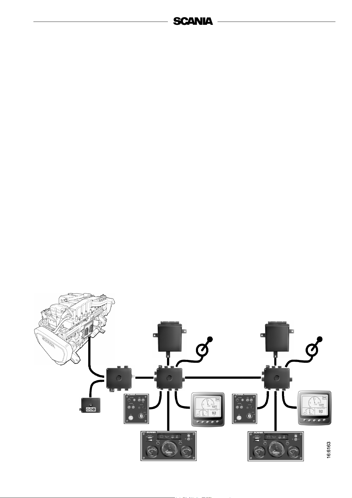
The base system comprises of the main supply box (MSB), the
junction box for the coordinator (CBC) and the coordinator (COO).
The main supply box is connected directly to the S6 control unit.
For this base system there are several different options for connection
to the system:
- Scania EMS digital display together with a control panel with
ignition key.
- A remote control box which enables controlling the engine from the
engine room.
- An analogue instrument panel instead of the digital display or
together with it.
- A Scania APS sensor (accelerator pedal sensor).
- In addition, the system can be doubled if there are two control
pulpits.
The whole system for instrumentation is Plug and Play which makes it
very simple to install.
See illustration of dual system on the next page.
In this Operator's manual, only the analogue instrument panel 9,
Scania EMS display 10 and Control Panel, 8 and 9, are described.
4
©
Scania CV AB 2008-03:1 1588955
Page 5
1
10
3
7
4
8
12
9
9
2
10
5
10
6
1588955
11
11
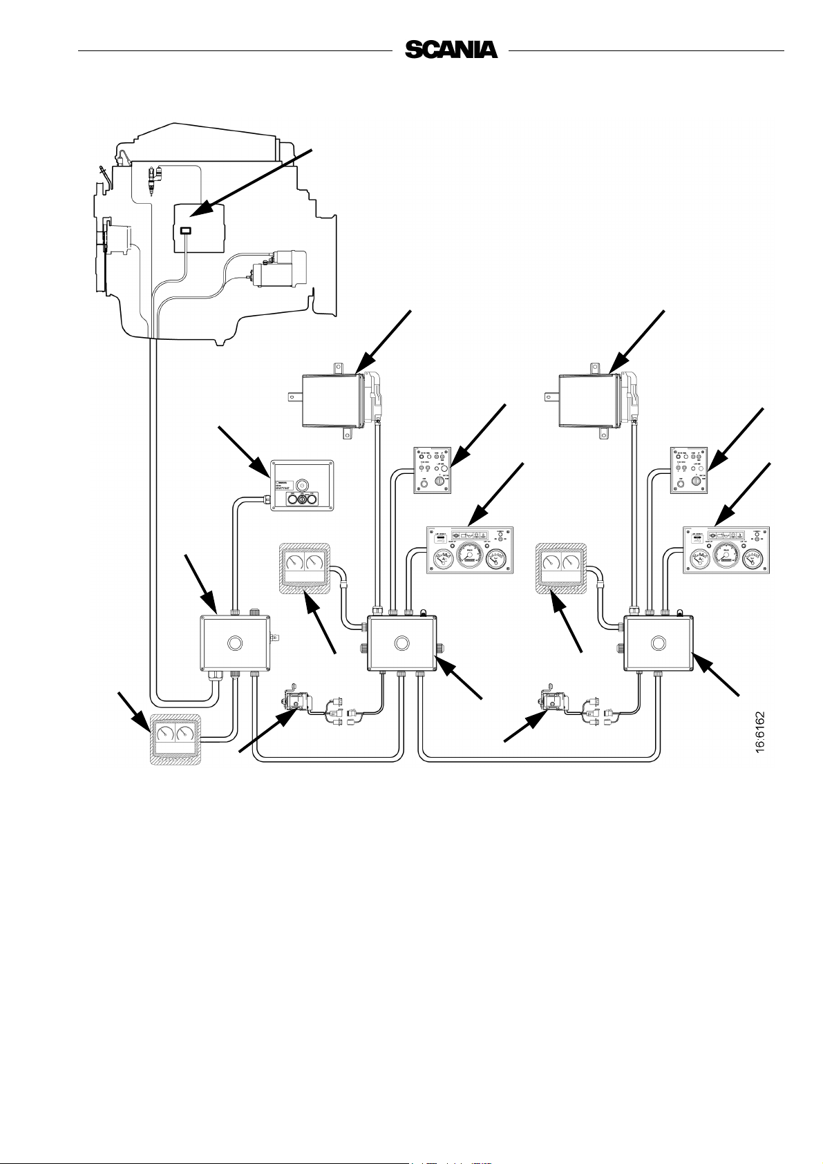
1. Control Unit S6
2. Main Supply Box
3. Coordinator
4. Coordinator
5. Connection Box Coordinator (master)
6. Connection Box Coordinator (slave)
7. Control Panel (master)
8. Control Panel (slave)
9. Instrument Panel
10. Scania EMS Display
11. Accelerator Position Sensor
12. Remote Control Box
Scania instrumentation, dual system
©
Scania CV AB 2008-03:1 5
Page 6

Instrument Panel (analogue)
General
The analogue instrument panel has instruments for reading rotation
speed with hour counter, coolant temperature and oil pressure as well
as switches and lamps for diagnosis and alarm.
The analogue instrument panel has the following functions:
Also see illustration on next page.
Lamp intensity (S54)
The intensity of the gauges can be regulated with this roller control.
Buzzer off (S51)
This button deactivates the buzzer sound on any existing alarm. The
warning lamp for the current alarm trigger will continue to illuminate
until the fault is rectified.
Lamp test (S52)
With this button it is possible to check that the system lamps are intact
and functioning. When the button is activated the coordinator will
activate all lamps on the panel and the buzzer will sound. The lamps
illuminate and the buzzer sounds as long as the button is depressed.
When the key in the control panel is turned to the Ignition position an
automatic lamp test takes place for 2 seconds and the buzzer sounds for
1 second.
Diagnosis EMS/COO (W21 and S53)
This is a 3-position switch which belongs to diagnostic lamp W21. The
diagnostic lamp remains lit for as long as the system has an active fault
code.
When the switch is activated in the direction of the COO for at least 1
second, the coordinator will send out any fault codes as flash codes on
the diagnostic lamp (W21).
When the switch is activated in the direction of the EMS for at least 1
second, the coordinator will send out any fault codes for the EMS the
control unit as flash codes on the diagnostic lamp (W21).
6
©
Scania CV AB 2008-03:1 1588955
Page 7
In order to read flash codes with dual instrumentation it is necessary to
demand diagnosis from the instrument panel where the coordinator in
question is connected.
For further information on reading and deleting flash codes, see
Troubleshooting using flash codes.
Warning lamps (W1, W4, W5, W6, W7)
On the warning lamp panel there are warning lamps for alternator
charging, oil pressure, coolant temperature and coolant level. Warning
lamp for hydraulic pressure is not used.
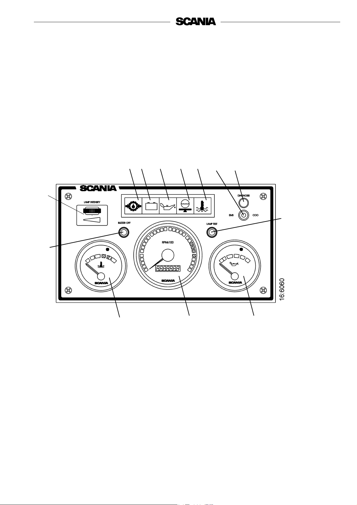
S54
S51
W6
W1
O2
O1 Tachometer with hour counter
O2 Coolant temperature gauge
O3 Oil pressure gauge
S51 Deactivation of buzzer
S52 Lamp test switch
S53 Diagnostic switch
S54 Rheostat for instrument lighting
W1 Charge warning lamp
W4 Warning lamp, coolant temperature
W5 Warning lamp, oil pressure
W6 Warning lamp, hydraulic pressure
W7 Warning lamp, coolant level
W21 Diagnostic lamp
W5
W7
O1
W4
S53
W21
S52
O3
1588955
Scania analogue instrument panel
©
Scania CV AB 2008-03:1 7
Page 8

Troubleshooting using flash codes for the EMS control unit
1. Switch on the ignition. If the diagnostic lamp is on after 2 seconds
there is an active fault.
2. Activate the diagnostic switch (S53) to the left to see the flash
codes for the control unit (EMS).
3. A fault code will then flash on the diagnostic lamp (W21). This
flash code consists of long flashes (approximately 1 second long)
and short flashes (0.3 seconds long). Long flashes are equivalent
to tens and short flashes to units.
Example: long - short - short = fault code 12.
4. Repeat this procedure until the first flash code is repeated. This
means that the entire fault code memory has been flashed out. If
the fault code memory is empty, only one long flash
approximately 4 seconds long will be given.
5. See the flash code table on the next page for a description and
localisation of the fault.
6. In order to obtain further information on the fault code, the
PC-based diagnostics tool or Scania EMS Display must be used.
Contact an authorised Scania workshop.
7. The diagnostic lamp will stay on for as long as a fault is active.
Even if the lamp has gone off and the fault is no longer active, the
code can generally be read off in accordance with the instruction
above.
8. When a fault has been rectified the fault code can be erased as
described below.
Erasing fault codes (flash codes)
1. Turn the ignition off. If there is dual instrumentation the ignition
must be switched off on both panels.
2. Activate the diagnostic switch in the direction of the flash codes,
i.e. to the left for EMS.
3. Turn the ignition on at the same time as holding the diagnostic
switch activated to the left (EMS) for 3 seconds.
4. This will erase passive fault codes which can be read off via flash
code for the relevant system. The rest of the fault code will remain
in the EEPROM and can only be deleted using the PC tool.
8
©
Scania CV AB 2008-03:1 1588955
Page 9

Overview of flashing codes for EMS control unit
Code Description
No fault detected.
0
11
12
13
14
15
16
17
18
20
Overspeed. One or both rotation speed
sensors are indicating values above 3000 rpm.
Rotation speed sensor 1 faulty, or incorrect
signal.
Rotation speed sensor 2 faulty, or incorrect
signal.
Coolant temperature sensor faulty, or incorrect
signal.
Charge air temperature sensor faulty, or
incorrect signal.
Charge air pressure sensor faulty, or incorrect
signal.
Oil temperature sensor faulty, or incorrect
signal.
Oil pressure sensor faulty, or incorrect signal.
Coolant level sensor faulty.
Code
53
54
55
56
57
58
59
61
66
69
Description
PDE in cylinder 3: The solenoid valve does not
work correctly.
PDE in cylinder 4: The solenoid valve does not
work correctly.
PDE in cylinder 5: The solenoid valve does not
work correctly.
PDE in cylinder 6: The solenoid valve does not
work correctly.
PDE in cylinder 7: The solenoid valve does not
work correctly.
PDE in cylinder 8: The solenoid valve does not
work correctly.
Incorrect signal in extra analogue input.
Incorrect control unit shutdown.
Shutdown due to coolant level
Starter motor function interrupted or not
activated.
23
24
25
27
28
31
32
33
37
43
47
Fault code internally in the coordinator.
Accelerator pedal / brake. If the accelerator
and brake pedals have been operated
simultaneously.
Accelerator pedal sensor / idling switch
Accelerator pedal sensor / kick-down switch
Engine shutdown bypassed.
Shutdown due to oil pressure
Torque limitation due to oil pressure
Incorrect parameters for limp home function.
Battery voltage incorrect or no signal.
Emergency shutdown switch activated in
accordance with CAN message from
coordinator.
CAN circuit faulty in the control unit.
Immobiliser function. Ignition key code
incorrect.
82
83
84
85
86
87
88
89
93
94
96
Rotation speed above ref.speed at start
Fault in memory circuit (EEPROM) in control
unit.
Data transfer to the control unit memory
(EEPROM) has been interrupted.
Incorrect temperature internally in the control
unit.
Internal fault in the control unit: Fault in
hardware control.
Fault in control unit RAM.
Internal control unit fault: Memory fault
Incorrect seal: Prohibited changes in software.
Rotation speed sensors faulty or not
connected.
Shutdown due to high coolant temperature.
Torque limitation due to high coolant
temperature.
48
49
51
52
1588955
CAN message from the coordinator incorrect
or missing.
Incorrect CAN version in control unit or
coordinator.
PDE in cylinder 1: The solenoid valve does not
work correctly.
PDE in cylinder 2: The solenoid valve does not
work correctly.
©
Scania CV AB 2008-03:1 9
98
99
Incorrect voltage supply to one of the sensors.
Internal hardware fault in the processor (TPU).
Page 10

Troubleshooting using flash codes for the EMS coordinator
1. Switch on the ignition. If the diagnostic lamp is on after 2 seconds
there is an active fault.
Important! The diagnostic lamp only indicates faults for the
coordinator connected to the instrument panel from which the
flash codes are read.
2. Activate the diagnostic switch (S53) to the right to see the flash
codes for the coordinator (COO).
3. A fault code will then flash on the diagnostic lamp (W21). This
flash code consists of long flashes (approximately 1 second long)
and short flashes (0.3 seconds long). Long flashes are equivalent
to tens and short flashes to units.
Example: long - short - short = fault code 12.
4. Repeat this procedure until the first flash code is repeated. This
means that the entire fault code memory has been flashed out. If
the fault code memory is empty, only one long flash
approximately 4 seconds long will be given.
5. See the flash code table on the next page for a description and
localisation of the fault.
6. In order to obtain further information on the fault code, the
PC-based diagnostics tool or Scania EMS Display must be used.
Contact an authorised Scania workshop.
7. The diagnostic lamp will stay on for as long as a fault is active.
Even if the lamp has gone off and the fault is no longer active, the
code can generally be read off in accordance with the instruction
above.
Erasing fault codes (flash codes)
1. Turn the ignition off. If there is dual instrumentation the ignition
must be switched off on both panels.
2. Activate the diagnostic switch in the direction of the flash codes,
i.e. to the right for the coordinator COO.
3. Turn the ignition on at the same time as holding the diagnostic
switch activated to the right (COO), for 3 seconds.
4. Any fault code that can be read by a flash code for the system in
question will be deleted. The rest of the fault code will remain in
the EEPROM and can only be deleted using the PC tool.
Important! It is only possible to delete fault codes for the
coordinator that is connected to the instrument panel from
which deletion is carried out.
10
©
Scania CV AB 2008-03:1 1588955
Page 11

Overview of flash codes for EMS coordinator
Flashing
Fault description
code
1)
11
11
12
12
2)
1)
2)
Incorrect signal from the nominal rotation speed signal fine adjustment.
Incorrect analogue signals from the accelerator pedal sensor.
Incorrect analogue signal from the resistor module for governor setting.
Incorrect analogue signal from the resistor module for idling and fixed speed
setting.
13 No communication (EMS) with the engine.
14 Short-circuit in the tachometer signal cable.
15 Faulty atmospheric pressure sensor.
17 Short-circuit in the coolant temperature gauge signal cable.
18 Short-circuit in the oil pressure gauge signal cable.
19 Short-circuit in the oil pressure lamp signal cable.
21
Different versions of the communications protocol between the coordinator and
EMS.
22 Faulty start switch or short circuit.
23 The supply voltage is too high.
24 The supply voltage is too low.
25 Check value from end of line (EOL) is incorrect.
26 Road speed sensor signal missing or incorrect.
27 The signals from the RCB (Remote Control Box) switches are implausible.
28 Incorrect signals from the droop-setting switches.
29 Faulty remote start switch or short circuit.
31 No communication from the slave coordinator or the master coordinator.
32 Short circuit in the signal cable to the coolant temperature warning lamp.
33 Short circuit in the signal cable to the charge indicator lamp.
34 Incorrect signal from the Fixed speed switches.
35 Fault in CAN communication.
1) Single speed engine
2) All-speed engine
1588955
©
Scania CV AB 2008-03:1 11
Page 12

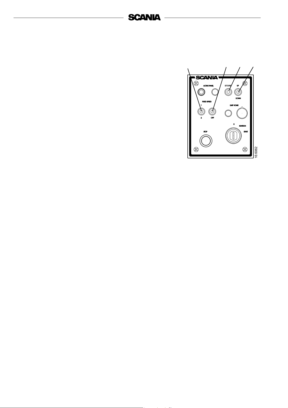
Scania Control Panel (SCP)
Start and stop the engine from the Scania Control Panel which has a
starter key and a stop button together with functions for Fixed Speed
and Limp Home.
S42 W19
S49
S43
S46
S45
S47
W20
S1
S50
W20
12
1. Master panel
2. Slave panel
W19 Lamp for Active Panel
W20 Lamp for Limp Home Throttle
S1 Ignition key
S42 Switch for Active Panel function
S43 Switch for activating and switching between Fixed Speed 1 and 2
S45 Switch for storing
S46 Stop button
S47 Switch for adjusting Fixed Speed / idle speed up or down
S49 Switch for deactivating Fixed Speed function
S50 Potentiometer for Limp Home Throttle
12
Scania Control Panel with ignition key
©
Scania CV AB 2008-03:1 1588955
Page 13

Following functions are available in Scania Control Panel:
Active Panel
Activate the panel by depressing pushbutton S42. The coordinator
registers that this control position is active and switches on lamp W19.
The panel from which the engine is started is automatically active and
it is then possible to make adjustments and requesting throttle
actuation.
In order to change active panel (changing throttle position) both
throttle controls must be at 0% throttle. Switch off the active panel so
that neither panel is active. Then it is possible to change control
position.
With single instrumentation, the panel is activated when the key is
turned to the ignition position.
If the throttle control fails, the Active Panel lamp is still illuminated
and the Limp Home lamp comes on which means that the limp home
throttle (emergency throttle) is engaged.
If CAN communication fails, the Limp Home lamp comes on and the
Limp Home throttle is engaged.
See also under Limp Home Throttle.
S42
W19
1588955
©
Scania CV AB 2008-03:1 13
Page 14
Fixed Speed 1 and 2
These two functions are activated via a 3-position switch, S43. With
Fixed Speed 1 it is possible to set an isochronous speed between high
and low idle speed. With Fixed Speed 2 it is possible to set an
isochronous speed between 450 and 2000 rpm. In both modes, it is
possible to set torque limitation via diagnostic tool or the digital
display.
When activating, the engine goes up or down to the last saved value for
the mode.
It is a prerequisite for activating these modes that the engine is running,
that the panel is active and that the throttle is at 0%.
Change the speed for either modes in the following way:
- Activate the mode to be changed by activating switch S43 to 1 or 2.
- Adjust the speed up or down using switch S47.
- Press Store switch S45 for 3 seconds to save the new values. If you
exit the mode without saving, the engine will resume the latest
speed value that was stored for that mode.
- With dual instrumentation, it is only possible to make adjustments
from the panel that is active.
S43
S49
S45
S47
- In order to deactivate the function, press switch S49 to Off, touch
the accelerator pedal, change panel when using dual
instrumentation, or switch off the engine.
14
©
Scania CV AB 2008-03:1 1588955
Page 15

Idle speed adjustment
Adjust the engine idle speed as follows:
1. Activate Store switch S45 for 3 seconds in order to go to
adjustment mode.
2. Adjust the idle speed up or down (+ or -) using switch S47.
3. Save the set value by activating the Store switch for
3 seconds.
- It is also possible to set the engine idle speed using the diagnostic
tool or Scania digital display.
- In order to adjust the idle speed, the coolant temperature must be
higher than 50°C and the engine running at idle.
- The idle speed can be set to between 500 and 1,050 rpm.
Stop
The function stop the engine is available in several places in the
system.
S45
S47
With single instrumentation, the stop button can be located in 2 places:
- In the Remote Control Box (RCB).
- In the Control Panel (S46).
With dual instrumentation, the stop button can be located in 3 places:
- In the Remote Control Box (RCB).
- In both Control Panels (S46).
When one of these buttons is activated COO sends a message to S6 to
stop the engine.
It is also possible to stop the engine by turning the key to O. With dual
instrumentation it is possible that both Control Panels are in ignition
position and both keys must then be turned to O.
Therefore we recommend that the engine is stopped with a stop
button.
S46
1588955
©
Scania CV AB 2008-03:1 15
Page 16

Limp Home Throttle
Limp Home Throttle is an emergency function that is activated if the
master coordinator fails or if the master throttle control fails while the
master control panel is active, or if the slave throttle control, slave
coordinator fail while the slave control panel is active or CAN traffic is
not working.
If this happens Limp Home lamp W20 will come on and Limp Home
Throttle will be engaged.
Limp Home Throttle, S50, consists of a potentiometer on the master
Control Panel with which it is possible to drive in limp home mode.
The potentiometer value goes directly to switch A2 on the S6 control
unit.
In order to use Limp Home Throttle the potentiometer must first be
turned to the 0 position before it is activated. The potentiometer is only
on the Master Control Panel. There is a Limp Home lamp on both
panels. If CAN fails, both lamps will come on and Limp Home Throttle
is activated.
The potentiometer is only on the master panel but Limp Home lamp
W20 is on both panels.
W20
S50
If the master control fails when the master panel is active, the lamps on
both panels will come on. If you then change to the slave panel, both
lamps will go off and it is possible to control the engine throttle via the
slave panel.
The same will also apply the other way round.
Start Key
Start the engine by using key S1 on Scania Control Panel. The key
gives U15 signal in the Ignition position and U50 signal in the Start
position.
When the coordinator receives a signal from the key to start, the
coordinator sends a CAN message to the S6 control unit, which in turn
sends a signal to the starter relay that supplies the starter motor with
power and the engine starts.
- If one panel is active, it is only possible to start from that panel.
- If no panel is active, the panel that you use to start the engine will
automatically become active.
The engine stops when the key is turned to the 0 position. In dual
systems, this only applies if the other key is not turned on.
S1
16
©
Scania CV AB 2008-03:1 1588955
Page 17

Remote Control Box (RCB)
Remote Control Box is connected on switch C57 on Main Supply Box
(MSB). With RCB it is possible to lock the engine so that it is not
possible to operate it from another position than where the RCB is
located.
Note: This can only be done when the boat is moored, i.e.
when there is no risk that the boat will drift out of
control. There is a sign on the RCB with this warning
text.
- There are two positions for key switch S26: Local and Remote.
- Local: The engine cannot be operated from any other location
than from the RCB box.
- Remote: Normal position, the engine can be operated from the
other throttle control positions.
- When the Local position is activated the green lamp 2 is
illuminated. At the same time the Active Panel lamps on the Scania
Control Panel (Slave and Master) starts to flash, which indicates
that neither of these panels can be activated.
- When the engine is started from the RCB using S27 it only runs on
idle as long as the Local position is activated and no other throttle
control can be used.
- If the key switch is reset from Local to Remote when the engine is
running, the green lamp 2 will go out and the engine will continue to
run on idle, but it will then be possible to operate throttle control
from other control positions if the Slave or Master panel is active.
- If key switch S26 is reset from Remote to Local while driving,
nothing will happen, except that this will be regarded as an
unintentional action.
- If CAN communication fails when the engine has been started from
the RCB the engine will stop but the Limp Home function will not
be engaged.
1588955
©
Scania CV AB 2008-03:1 17
Page 18

- In order to start the engine again, it is necessary to carry out the
following procedure:
- Connect pin 50 on the starter relay with the plus pin on the
starter motor. The engine starts but it is only possible to control
the throttle using the Limp Home potentiometer
- In order to stop the engine you must switch off the power to EMS
S6 by turning the starter key to 0 or via switch C122 in the MSB.
1
S27
S26 S28
1 Green indicator lamp
S26 Rotary switch for activating the Local function
S27 Starter button
S28 Stop button
Scania Remote Control Box (RCB)
18
©
Scania CV AB 2008-03:1 1588955
Page 19

Scania EMS Display (SED)
General
Scania EMS Display is a graphic display which represents engine data,
diagnostics which enables settings of certain parameters in the engine
control unit EMS. Scania EMS Display can only be used together with
EMS and the new electrical system adapted for marine use.
Communication to and from the display is carried out via CAN bus,
protocol J1939.
Function
The information content can be found in different screens according to
a tree structure. On the upper level there are six different screens, three
Favourites, Information, Diagnostics and Settings.
The buttons are configured to function differently depending on which
screen is currently active. To scroll between different screens on the
upper level, use button 1 and 5 depending on whether you want to
move forwards or backwards in the structure.
When one of the favourite screens is active, the information about each
button's function is hidden. The reason for this is to make as big an area
as possible available for presentation. As soon as a button is depressed,
the description for the button is displayed for approx 5 s.
Each window (except the favourites) has a number in the upper left
corner. The numbers indicate the current screen and level.
Favourite screen
The screen Favourites is used to display engine data during operation,
more or less equivalent to Scania analogue instrument panel. The
favourite screen can have three different appearances, all on the
highest level.
1588955
©
Scania CV AB 2008-03:1 19
Page 20

If you want to change from one Favourite to another Favourite, press
button 1 or 5 depending on which is currently displayed.
On this screen, the buttons have the following functions:
1 Scroll to the left in the upper level
2
3
4 Go down one level in the structure
5 Scroll to the right in the upper level
Change the appearance of a Favourite by pressing button 4.
The button screen shown on the right, will then be displayed.
By pressing button 2 the appearance of the screen changes according to
the order on page 19.
When an appearance has been selected, it is possible to change the
contents of the selected window.
Press button 4 to display the button bar according to the table below.
- In order to select the contents for a partial window, it must be
active.
- Activate the partial window by pressing button 2. The window will
then be greyed out.
1 Changing between digital and analogue signal
2 Changing between greyed active partial screen
3 Changing of signal in greyed active partial screen
4
5 Go up one level in the structure
20
©
Scania CV AB 2008-03:1 1588955
Page 21

- Change the active partial window by pressing button 2.
- The contents of the partial window is changed with button 3 and 1
according to the following table:
The information of the different partial windows can be displayed in
digital or analogue format. Some signals can only be displayed in one
format, see the table.
- Press button 1 to change between analogue and digital display (1).
- Press button 3 to change the content of the active partial window
(2).
Signal
Engine speed Yes Yes
Oil pressure Yes Yes
Coolant temperature Yes Yes
Charge air pressure Yes Yes
System voltage Yes Yes
Fuel consumption Yes No
Load at current speed Yes No
Engine hours Yes No
Throttle Yes No
Digital
display
Analogue
display
Symbol
RPM
1
2
1
1588955
2
©
Scania CV AB 2008-03:1 21
Page 22

Information (4)
Carry out the following in order to go to this screen from the basic
screen (favourite):
- Press any button to display the button bar.
- Press button 5 one to three times (depending on which favourite that
is active) to go to screen 4 INFORMATION.
- The button bar will now stay on the screen.
- Buttons 2 and 3 are used to move up or down in this screen.
- Press button 4 to go down one step in the structure to STATISTICS
TRIP (4.1).
- Here is some information according to the screen.
- Press button 1 (Reset) in order to zero the reading.
- In order to go back to screen 4, press button 5.
- Maximum time for a registered reading is 999 h, then Reset will be
automatic.
x1-3
- Go down one step with button 2 to PERFORMANCE.
- Press button 4 to go down one step in the structure to
4.2 PERFORMANCE.
- The information displayed here is the current performance at that
time, i.e. the displayed values are real-time. Corresponding values
can also be read in the Favourite window, but this is a quicker way
to get a summary of the performance related parameters.
22
©
Scania CV AB 2008-03:1 1588955
Page 23

- In order to go back to screen 4, press button 5
- Go down one step with button 2 to SYSTEM DATA.
- Press button 4 to go down one step in the structure to
4.3 SYSTEM DATA.
- Here it is possible to select information about the four different
system control units.
- If you select EMS and press 4, information about the engine, engine
number and engine type and the EMS control unit part number will
be displayed.
- If you select DISPLAY the following information about Scania EMS
Display is displayed:
- Part number (complete)
- Hardware number
- Software number
- Version number
- The corresponding information is retrieved for the coordinators if
the COO MASTER or COO SLAVE is selected.
1588955
©
Scania CV AB 2008-03:1 23
Page 24

Fault codes (5)
- Return to screen 4 INFORMATION by pressing twice on 5. If you
press button 5 again, screen 5 FAULT CODES. is displayed.
- The upper symbol to the right indicates that there is at least one
active fault code.
- The button bar has a different appearance and it will be displayed
the whole time. Refer to the table below.
1 Scroll to the left in the upper level
2 Go down to the next line in the list
3 Short press: Up to the next line in the list
Long press (3 s): Update the list
4 Short press: Information about the highlighted fault code
Long press (3 s): Clear fault codes
5 Scroll to the right in the upper level
- In the example, the Coolant temp sensor and Oil pressure sensor
marked by a ! which means that they are active fault codes.
Information about the highlighted fault code
In the example, Coolant temp sensor is black. By a short press on
button 4 the information screen about the fault code is displayed.
Information type Description
Affected control unit The control unit where the fault originated,
e.g. EMS
Name of fault Fault code name, e.g. Coolant temp sensor
System behaviour How the system is behaving when the fault
is active, for example Problems starting
Code The number of the selected fault code, e.g.
2001
Status If the fault is active
Hex code Gives more information than just status,
e.g. 20
or passive
Times How many times that the fault has occurred,
e.g. 3
24
©
Scania CV AB 2008-03:1 1588955
Page 25

To erase fault codes
- Press button 4 for three seconds.
- A screen asking if you want to erase all fault codes is displayed.
- Press button 1 to erase all fault codes.
- Then press button 3, OK, to confirm.
3 s
Update the fault code list
- Update the fault code list by pressing button 3 for three seconds.
- Confirm by pressing button 3, OK.
3 s
1588955
©
Scania CV AB 2008-03:1 25
Page 26

Settings (6)
- Press button 1 or 5 from the Favourite screen to go to screen 6
SETTINGS.
- In order to quickly go to the setting mode, irregardless of where you
are: Press buttons 2 and 4 simultaneously.
CONTRAST / BRIGHTNESS (6.1)
- Using buttons 2 and 3 to go up or down in the list.
- Press button 4 to go to the adjustment screen for
CONTRAST / BRIGHTNESS.
- Here it is possible to adjust the brightness and contrast to the current
operating conditions.
- In order to reset to the original setting, press buttons 2, 3 and 4 at the
same time for three seconds.
BUTTON BLEEP (6.2)
- Press button 2 to go to BUTTON BLEEP.
- Press button 4 to go to the adjustment screen.
- Press button 3 to change between BUTTON BLEEP OFF or
BUTTON BLEEP ON
- Press button 5 to return to the selection screen.
- The setting BUTTON BLEEP OFF does not affect the alarm signal.
26
©
Scania CV AB 2008-03:1 1588955
Page 27

LANGUAGE (6.3)
Information on Scania EMS Display can be displayed in seven
different languages:
Swedish English German French Spanish
Italian Portuguese
The default language is English
- Press button 2 or 3 to go to LANGUAGE.
- Press button 4 to go to the selection screen.
- Press button 2 or 3 to select language.
- Press 4 to confirm the change. The box to the right about selecting
language will then be marked, which means that the change has
taken place.
- Press button 5 to return.
UNITS (6.4)
It is possible to select between two different sets of units for different
parameters according to the table:
METRIC
US IMPERIAL
Parameter Metric US Imperial
Pressure Bar Psi
Voltage V V
Engine speed Rpm Rpm
Temperature °C °F
Fuel consumption L/h, L Gal/h, Gal*
*) US Gallon = 3.79 l
- Press button 2 or 3 to go to UNITS.
- Press button 4 to go to the selection screen.
- Press button 2 or 3 to select unit system.
1588955
©
Scania CV AB 2008-03:1 27
Page 28

- Press button 4 to confirm the change. The box to the right will then
be marked, which means that the change has taken place.
- If you press button 1, information according to the table above is
displayed.
- Press button 5 to return.
ENGINE (6.5)
From this screen it is possible to change the basic settings of the engine
when it was delivered.
Note: Changing basic settings may affect safety-critical
functions.
- Press button 2 or 3 to go to ENGINE.
- Press button 4 to confirm the selection.
- To prevent unintentional changes, this function is passwordprotected. The password has a default setting of "2 2 2 2" but can be
changed by the end-customer, see 6.5.9.
Enter the password and press button 4 to proceed.
- A screen with a warning is displayed. Press button 3 OK, to proceed
to the parameters that can be set.
On the first screen, 6 parameters are displayed and by pressing button
2, you can access the two last parameters.
There is a short description below about the engine settings that can be
made from this screen:
IDLE SPEED (6.5.1)
Low idling on a warm engine can be set between
500 and 1,050 rpm. It is not possible to reset the idle speed value if the
coolant temperature is below 50°C. If the engine is running on a raised
idle speed for any reason, the idle speed cannot be reset either
28
©
Scania CV AB 2008-03:1 1588955
Page 29

LOW TEMP LIMIT (6.5.2)
The lower temperature limit, which has the basic setting 95°C (203°F),
is the level for the alarm and torque reduction if this has been selected.
See page 33 for an example.
It is possible to set this level between 85°C (185°F) and 105°C
(221°F). The lower limit cannot be set above the upper temperature
limit.
HIGH TEMP LIMIT (6.5.3)
The upper temperature limit, which has the basic setting 105°C
(221°F), also makes it possible (in addition to the alarm function) to
stop the engine automatically.
It is possible to set this level between 95°C (203°F) and 105°C
(221°F). The upper limit cannot be set below the lower temperature
limit.
FIXED SPEED 1 (6.5.4)
Setting of upper torque limit:
This is an isochronous idle speed which can be set and activated from
Scania Control Panel. See page 14.
On Scania EMS Display it is then possible to set an upper torque limit
for FIXED SPEED 1. This setting only applies when FIXED SPEED 1
is activated.
FIXED SPEED 2 (6.5.5)
Setting of upper torque limit:
This is an isochronous idle speed which can be set and activated from
Scania Control Panel. See page 14.
On Scania EMS Display it is then possible to set an upper torque limit
for FIXED SPEED 2. This setting only applies when FIXED SPEED 2
is activated.
SAFETY SWITCH (6.5.6)
The safety switch (idle switch) is a safety function in Scania's electrical
system which checks that the accelerator pedal is functioning correctly.
The component is a closing switch that is activated when the
accelerator pedal position is greater than zero.
The function can be disengaged.
Note: A safety function is then disconnected.
FUEL DENSITY (6.5.7)
Fuel density affects the calculation of the engine power and it can be
noted here. Default is 840 kg/m3 and the setting range is
700-1,000 kg/m3.
1588955
©
Scania CV AB 2008-03:1 29
Page 30

ALARM REACTION (CMOL) (6.5.8)
The engine behaviour may vary depending on how EMS is
programmed.
Signal Line EMS behaviour
1 Only alarm with fault
Low oil
pressure
High coolant
temperature
Low coolant
level
2 Alarm and torque reduction
3 Alarm and engine stop
4 Engine stop and override
1 Only alarm with fault
2 Torque reduction
3 Engine stop
4 Torque reduction at the lower temperature limit
Engine stop at the upper temperature limit
5 Engine stop and override
6 Torque reduction at the lower temperature limit
Engine stop at the upper temperature limit and
override
1 Only alarm with fault
2 Alarm and torque reduction
3 Alarm and engine stop
4 Engine stop and override
- Press button 2 to go to ALARM REACTION.
- Press button 4 to go down one level.
- Select signal type using button 2 or 3 and go down to the EMS
function using button 4.
+
30
©
Scania CV AB 2008-03:1 1588955
Page 31

- Select the EMS function using button 2 or 3. On the displayed
screen: ONLY ALARM.
- Press 4 to confirm the selection. The box to the right will then be
marked, which means that the change has taken place.
- Press button 1 to get a more detailed description of the selected
EMS function.
- Press button 5 to return.
1588955
©
Scania CV AB 2008-03:1 31
Page 32
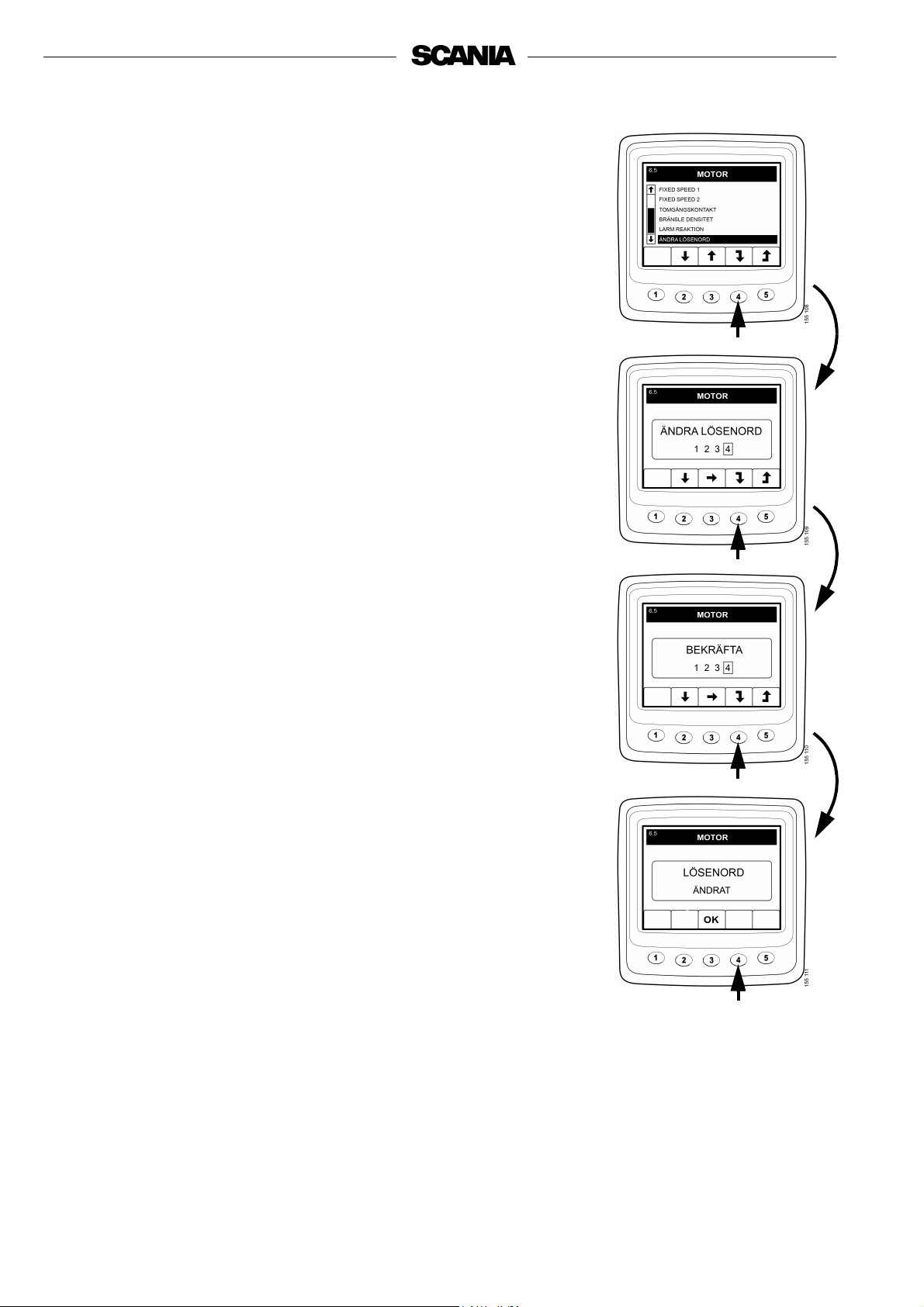
CHANGE PASSWORD (6.5.9)
A new password can be set, the valid values are 0001 - 9999.
- Press button 4 to change the password.
- Enter the desired password and press button 4
- Press button 4 to confirm the password.
- Press button 4 to return.
Note: If you have forgotten the password, contact your
nearest Scania representative.
32
©
Scania CV AB 2008-03:1 1588955
Page 33

Example
Setting of LOW TEMP LIMIT (6.5.2)
- Press button 4 to proceed.
- Enter the password and press button 3
A warning is displayed.
- Press button 3 OK, to confirm the warning and proceed to the
parameters that can be set.
- Press button 2 or 3 to move up or down in the selection screen.
- Press button 4 when for example LOW TEMP LIMIT has been
selected.
- Press button 4 again to display the setting screen.
- Press button 2 or 4 to increase or decrease the setting value.
- Press + or - and automatic deletion of old values and the new value
is entered.
- Press button 5 to return.
The same settings can be made for the other parameters.
1588955
©
Scania CV AB 2008-03:1 33
Page 34

BASE SYSTEM (6.6)
Here it is possible to configure Scania EMS Display for the electrical
system to be used. The alternatives are NO, SINGLE or DOUBLE.
- Press button 2 or 3 to go to BASE SYSTEM.
- Press button 4 to go to the selection screen.
- Press button 2 or 3 to select base system.
- Press button 4 to confirm the change. The box to the right will then
be marked, which means that the change has taken place.
- Press button 5 to return.
Alarm and fault code generation
Both new alarms and fault codes create dialogue boxes (so-called popup boxes).
The dialogue box for alarm has the highest priority for all functions in
Scania EMS Display.
Alarm
There are four different alarms available in the system:
Alarm Icon Remarks
Low oil pressure
High coolant temperature
Low coolant level
Alternator does not charge System voltage
displayed
34
©
Scania CV AB 2008-03:1 1588955
Page 35

Function
When an alarm is created it is displayed as a warning on the basic
screen together with the alarm icon. The alarm signal sounds at the
same time both on the instrument panel and on Scania EMS Display.
Alarm signal on Scania EMS Display is confirmed by pressing button
3, OK. If there are more alarms (icons), one alarm has to be confirmed
at a time. Screen 1.
Each confirmed alarm is then displayed as an icon in the upper right
corner of the screen as long as a fault is active, irregardless of which
screen is active.
Note: All alarms must be confirmed before the next screen will be
displayed.
The screen in illustration 2 always has the same content.
If you press button 3, OK when in screen 2, you will return to the
screen displayed before the first alarm was generated. Screen 3.
1.
2.
External alarm signal
Output for external alarm
As soon as an alarm is present, pin 11 on the 12-pin display connector
is activated. The output can be used to activate a warning lamp or
suchlike. Pin 11 must be connected to earth a lamp or a relay connected
to +24V.
Maximum current 200mA.
3.
1588955
©
Scania CV AB 2008-03:1 35
Page 36

Fault code generation
There are several fault codes in the electrical system to help when a
system fault or engine fault occurs.
When a new active fault code is registered in the system, it will be
displayed on the screen as in illustration 1.
Confirm all active fault codes by pressing button 3, OK. In the next
screen, a spanner icon is displayed in the upper right corner. Screen 2.
This is displayed when at least one fault code is active.
It is not possible to view the number of active fault codes from these
screens. To view active fault codes, go to the description of Fault
codes on page 20.
When starting the system a dialogue box as in illustration 1 is
displayed if there is at least one active fault code.
1.
2.
36
©
Scania CV AB 2008-03:1 1588955
 Loading...