

Page 1
00:45-52
Issue 1
Dismantling information
Bus
FKN series
en
©
Scania CV AB 2010, Sweden
Page 2

Work description
General information
This information is aimed at all people dealing
with reconditioning and scrapping of Scania
vehicles. The information applies to workshops
as well as dismantling and recycling companies.
The information is applicable to all Scania
models. However, not all parts are covered by
this information booklet. The information is
incomplete.
Drainage and removal describes how
environmentally hazardous waste should be
removed from the vehicle (pre-treatment).
The purpose of identification of materials is to
facilitate identification and sorting of materials
for recycling.
Page 3

Drainage and removal
Fluids and materials that are harmful to the environment
The following list is a guide of lubricants, fluids
and parts that are recovered from the bus during
pre-treatment. The volumes are approximate.
IMPORTANT! Avoid spillage and use a
collecting vessel when handling hazardous
fluids.
Engine: Specification Quantity
9 litre engine
12 litre engine
13 litre engine
Oil filter Oil 2 l
Fuel filter Diesel/Ethanol -
Compressor Oil 0.4 l
Fuel tank Diesel/Ethanol -
Catalytic converter - -
Cooling system: Specification Quantity
9 litre engine
12 litre engine
13 litre engine
Hydraulic cooling fan Oil 15 l
Power train: Specification Quantity
Clutch Brake fluid 0.5-1.0 l
Manual gearbox Oil 9-11 l
Automatic gearbox ATF oil 30-50 l
Oil 29-35 l
22 l
40 l
Coolant 40 l
50 l
50 l
Opticruise Oil 0.3 l
Scania Retarder Oil 7.5 l
Rear axle gear Oil 10-18 l
Rear axle, oil filter Oil filter 0.5 l
Rear steering tag axles ATF oil 3.9-4.6 l
Compressed air tanks - -
Steering: Specification Quantity
Power steering ATF oil 6-9 l
Hydraulic unit for articulated buses ATF oil 2.8 l
Page 4

AC: Specification Quantity
Climate control system Refrigerant R134a 8-15.5 kg
Electrics: Specification Quantity
Starter battery - -
Wheels: Specification Quantity
Balancing weights Lead -
Page 5

!
WARNING!
Isocyanates are found in some paints,
putties, adhesives and plastic foams,
etc., that are used in motor vehicles.
Inhaling isocyanates in the form of
vapour, dust or aerosols may cause
irritation of mucous membranes causing
asthmatic symptoms from the
respiratory passages and an impaired
function of the lungs. Even brief
exposure to high concentrations can
cause problems of permanent
hypersensitivity.
When products containing isocyanates
in combined form are heated to
temperatures above 150°C, isocyanates
are set free. This results in a high degree
of exposure.
This applies for example to grinding,
welding and cutting products to which a
top coat of paint containing isocyanates
has been applied. For this reason, make
sure that there is adequate ventilation in
the areas where the work is carried out.
Personnel carrying out such work
should use protection, such as
respiratory masks with air supply.
Do not take any risks when working with
heated materials that might contain
isocyanates; always presume that the
material contains isocyanates and take
necessary safety precautions.
Page 6

!
WARNING!
Where a vehicle is involved in a fire, a
number of substances that are
hazardous to health and the
environment are formed. Smoke and
water carry these substances and they
remain in the vehicle to a certain extent
(ashes).
When dismantling a vehicle that has
been involved in a fire, the following
should be taken into consideration:
Use protective equipment such as
respiratory protection and gloves when
working on vehicles which have been
involved in a fire. Avoid skin contact
with ashes.
The vehicle may be weakened, which
can have a negative affect on lifting
points. This should also be taken into
consideration when tilting cabs.
Gas dampers that have not been
punctured represent an explosion risk,
as the material they are made of may be
weakened and/or damaged.
Wash the vehicle before starting
dismantling.
Keep the following in mind:
Do not start dismantling before the
cause of the fire has been fully
investigated.
Power should be disconnected on
vehicles which have been involved in a
fire as soon as possible, by
disconnecting the battery cables. This is
to prevent short circuits, which can
result in a new fire.
Corrosion is accelerated on vehicles
which have been involved in a fire, for
example due to moisture in combination
with ashes and some extinguishing
medium. The vehicle should be
processed as soon as possible, to
minimise the risk of undesirable leakage
of environmentally hazardous fluids and
substances.
Page 7
Burnt vehicles should be washed in a
!
WARNING!
!
WARNING!
!
WARNING!
!
WARNING!
way that allows the washing water to be
disposed of in an environmentally
responsible way, as it contains
environmentally hazardous
contaminants.
When carrying out any type of work
which involves heating products, the
relevant safety regulations for this type
of work should be followed.
Cut the power to the vehicle before
starting work.
The system must be depressurised
when working with air bellows.
Risks in connection with ethanol
• Ethanol fuel is extremely flammable
and must be handled with great care.
Like petrol, ethanol is classified with
a flammability class.
• Ethanol fuel is hazardous to health. If
ethanol has come into contact with
eyes or skin, flush with water.
• Ventilate properly when handling
ethanol.
Page 8

• Ethanol fumes can form an ignitable
!
WARNING!
mixture with air at approximately
9°C, both in closed and open
containers.
• The fumes are heavier than air and
therefore spread along the ground
and can catch fire a long way from
the source.
• Avoid free-falling jets; otherwise
there is a risk of static electricity,
which would cause sparks.
• Prevent sparking through
equipotential bonding (grounding).
• Ethanol burns with a barely visible
flame and no smoke. Burning
ethanol is therefore hard to detect in
daylight.
Safety precautions and equipment in
connection with ethanol
• Comply with local regulations when
handling ethanol fuel.
• Establish ethanol decontamination
routines for workshop work. There
must be sand or Absol for
decontamination.
• Store ethanol spillage in a marked,
closed collecting vessel specially
designed for ethanol fuel and in a
manner that ensures it is not
confused with diesel.
• Wear protective gloves and goggles
resistant to ethanol when handling
the fuel. Cotton clothes are
recommended.
• Powder is the best extinguishing
medium for putting out ethanol fires.
Page 9
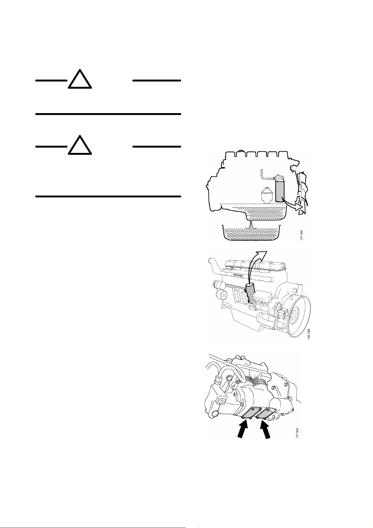
Engine
!
WARNING!
!
WARNING!
Beware of hot oil after driving. Wear
protective goggles and gloves.
Ethanol fuel is extremely flammable and
must be handled with great care. Like
petrol, ethanol is classified with a
flammability class.
1 Drain the engine oil.
2 Remove the oil filter. Also drain the oil
from the centrifugal oil cleaner reservoir.
3 Remove the fuel filter element. Use suction
on the filter housing if necessary.
Note: The fuel system may be pressurised.
Release the pressure before dismantling.
4 Drain the oil from the compressor by
unscrewing the blanking pieces.
Page 10

Fuel tank
!
WARNING!
Diesel
1 Check or estimate how much fuel is in the
fuel tanks. Make sure that there is enough
room for the fuel in the collecting vessel.
2 Drain the tank by unscrewing the drain plug.
Note: Some tank variants do not have a drain
plug. Some bus bodybuilders have their own
tanks. Check their instructions.
Ethanol
Ethanol fuel is extremely flammable and
must be handled with great care. Both
ethanol and petrol are classified as
flammability class 1.
Note: Before the vehicle is taken into the
workshop, check whether the fuel system is
leaking ethanol. The recommended method is to
leak test the fuel system using measuring
instrument 588 875. Check that the measuring
instrument has been calibrated as described in
the instrument documentation before it is used.
1 Check or estimate how much fuel is in the
fuel tanks. Make sure that there is enough
room for the fuel in the collecting vessel.
2 Connect the fuel tank to be drained with the
pump and the collecting vessel via a ground
connection.
3 Pump away as much ethanol as possible
through the filler pipe. Make sure that the
pump hose reaches the bottom of the
collecting vessel to prevent the formation of
static electricity. Repeat for all fuel tanks
with a filler pipe.
Page 11

4 Check that there are no ethanol fumes
151 973
around the vehicle by checking for leaks
using, for example, measuring instrument
588 875.
5 Jack up the vehicle.
6 Check the location of each fuel tank drain
plug.
Note: Some tank variants do not have a drain
plug. Some bus bodybuilders have their own
tanks. Check their instructions.
7 Carry out the following for all tanks:
• Connect a ground connection between the
fuel tank and the collecting vessel.
• Suspend a funnel under the drain plug.
Make sure the funnel is large enough for the
fuel that runs down when the drain plug is
undone. Try to keep free fall as short as
possible as free fall causes static electricity.
If possible, connect a hose that reaches the
bottom of the collecting vessel to the funnel.
• Undo the drain plug.
• Drain the remaining fuel.
8 Check that there are no ethanol fumes by
checking for leaks using, for example,
measuring instrument 588
875.
Page 12

Catalytic converter
The SCR catalytic converter contains vanadium.
Vanadium can constitute a health hazard.
The SCR catalytic converter is fitted in the
silencer and does not constitute a health hazard
during normal use and handling.
When carrying out work on the SCR catalytic
converter which may result in exposure to dust,
safety precautions must be taken. Such work
includes, for example, opening the silencer,
machining and scrapping the catalytic converter.
Safety precautions when working on the
SCR system
• Inhalation: If dust is inhaled, the person
should be provided with fresh air
immediately. If a significant amount of dust
is inhaled, seek medical attention.
• Eye contact: Rinse eyes with water
immediately. If irritation persists, seek
medical attention.
• Skin contact: Wash with soap and water.
Remove contaminated clothes.
• Ingestion: If large amounts have been
ingested, drink plenty of water and induce
vomiting. Seek medical attention.
Health hazards
• Inhalation of dust from the SCR catalytic
converter can constitute a health hazard as it
may cause irritation of the respiratory
system.
• Eye contact may cause eye irritation.
• Skin contact may irritate the skin.
• Ingestion can cause irritation in the mouth
and throat and produce discomfort. The
ingestion of large quantities may cause
disorders in the gastric and intestinal canals.
• There is a possible risk of permanent health
damage. There is also a risk of foetal
damage.
Environmental hazards
• Vanadium pentoxide is toxic to water
organisms and can cause detrimental longterm effects to the water environment.
Page 13

Environmental protection measures
!
WARNING!
• Any dust or spillages should be collected in
a container for recycling or disposal in
compliance with local regulations. It should
not be drained into watercourses or into the
general treatment system.
• A scrapped SCR catalytic converter should
be disposed of in compliance with the
relevant EU, national or local regulations.
The constituent parts are classified as
harmful to the environment by the EU.
Use protective goggles and gloves if
there is any risk of splashing or
spraying of reductant or coolant.
When the engine is running, the exhaust
system parts can reach such high
temperatures that there is a risk of
personal injury. Make sure that the
exhaust system temperature has fallen
to a suitable level before starting work.
The SCR system is heated by water from
the engine cooling system. The cooling
system runs at overpressure and when
the engine is hot the coolant is hot. Do
not open any hoses without first
stopping the coolant flow in the hose.
A P3 type respiratory protection/filter
mask, protective goggles and gloves
should be used for any work where
there is a risk of exposure to dust from
the SCR catalytic converter.
You should not eat, drink or smoke while
working.
Any dust from the SCR catalytic
converter should be removed using a
vacuum cleaner with microfilter to
minimise exposure.
Make sure you clean your hands after
working with a SCR catalytic converter
to avoid ingestion.
Page 14

Remove filter
1
3
5
2
6
4
309 113
1 Undo the exhaust pipe V-clamp 1.
2 Undo the exhaust pipe V-clamp 2.
3 Remove the exhaust gas temperature
sensor 3.
4 Undo the reductant doser fastening bolts 4
to facilitate injection nozzle pipe removal.
5 Remove the injection nozzle pipe 5.
6 Remove the silencer 6.
Remove the reductant tank
1 Clamp the hose 1 using pliers to stop the
coolant flow. Warning! The hose contains
coolant from the engine. Open the coolant
filler cap first to relieve any pressure.
2 Detach the retaining straps 2.
1
4
3
3 Remove the electrical connection 3.
4 Remove the hoses 4 from the combined tank
unit.
5 Remove the reductant pick-up unit.
Note: Only use containers and collecting vessels
manufactured from material recommended for
use with reductant.
2
309 112
Page 15

Coolant
!
WARNING!
The coolant system operates with
overpressure. There is a risk that hot
coolant may be emitted if the system is
opened while hot.
Hot coolant can cause burns.
Avoid skin contact with coolant. Skin
contact may cause irritation.
Always wear protective goggles and
rubber gloves when handling coolant.
Scania corrosion inhibitor, ethylene
glycol and other coolant additives can
be fatal if swallowed.
Page 16

Special tools
142 231
Number Denomination Illustration Tool board
99 301 Quick release coupling -
587 129 Complete coolant draining unit -
Note: Check bus bodybuilder’s instructions for
draining.
1 Open the heat outlet and heat return valves.
2 Carefully open the expansion tank cap. The
cooling system may be exposed to
overpressure.
3 Connect adapter 99 301 to the cooling
system drain and filler nipple and use
coolant tank 587 129 to drain and collect the
coolant. The nipple is located at the lower
coolant hose.
Note: The coolant volume increases when
components are connected to the cooling
system:
• Retarder + 20 litres
• Oil cooler and hose
• Auxiliary heater Webasto
Page 17

Hydraulic cooling fan
!
WARNING!
Beware of hot oil after driving. Wear
protective goggles and gloves.
1 Remove the oil connection between the oil
cooler and hydraulic motor.
Clutch
1 Connect a suitable collecting vessel to the
bleed nipple at the clutch housing.
2 Detach the hose from the connection, and
pump out the brake fluid using the clutch
pedal.
3 Drain the clutch fluid reservoir which is
located at the front of the bus.
Bleed nipple
Page 18

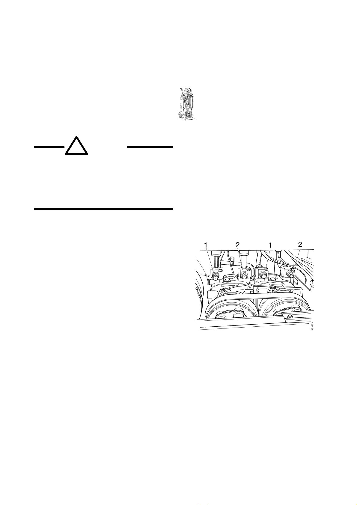
Manual gearbox
!
WARNING!
Beware of hot oil after driving. Wear
protective goggles and gloves.
1 Remove the drain plug and level plug.
Allow the oil to drain.
2 Remove the filter.
1 Level plug
2 Drain plug
3 Filter
Page 19

Automatic gearbox
!
WARNING!
Beware of hot oil after driving. Wear
protective goggles and gloves.
1 Put the drive mode selector in position N.
2 Remove the drain plug. Allow the oil to
drain.
3 Remove the oil filter cover and remove the
filter.
1 Drain plug
2 Oil filter cover
Page 20

4 Drill through the torque converter housing
and then through the torque converter.
Allow the oil to drain.
5 Drill through the underside of the angle gear
housing. Allow the oil to drain.
6 Remove the oil pipes on the gearbox oil
cooler. Allow the oil to drain.
Page 21

Opticruise
308 302
1 Remove the longitudinal stroke cylinder and
drain it from oil through the rectangular
opening.
Longitudinal stroke cylinder,
GZ gearbox
Longitudinal stroke cylinder,
TP gearbox
315 199
Page 22

Scania Retarder
!
WARNING!
142 231
587 129
99 301
307 398
Beware of hot oil after driving. Wear
protective goggles and gloves.
Make sure the compressed air tanks are
empty before starting work. Oil under
pressure or blows from loose parts can
cause personal injury.
Retarder, type 1
Special tools
Number Denomination Illustration Tool board
99 301 Quick release coupling -
587 129 Complete coolant draining unit -
1 Drain the coolant by connecting quick
release coupling 99 301 to the bottom of the
radiator. Remove the radiator cap to make
the coolant drain faster.
2 Put the retarder lever in position 5 and
switch on the ignition. This empties out
most of the oil volume from the
accumulator so that all the oil ends up in the
retarder sump.
Page 23

3 Undo the drain plug 1 under the planetary
2
1
308 304
308 305
3
4
gear and drain the oil.
4 Detach the hoses from the retarder.
5 Remove the oil filter 2.
6 Detach the hose 3 from the oil accumulator.
7 Blow out the remaining oil with compressed
air at the connection 4.
Retarder, type 2
1 Remove the plug 1 and drain the oil.
2 Drain the oil accumulator by turning the key
to the drive position (compressed air system
filled to working pressure) and move the
retarder lever between the 0 position and
maximum position several times, waiting
for 5 seconds at each end position.
3 Remove the oil filter 2.
R4
M1
2
1
311 976
Page 24

Rear axle gear
!
WARNING!
Beware of hot oil after driving. Wear
protective goggles and gloves.
1 Remove the drain plug and level plug.
Allow the oil to drain.
2 Remove the oil filter.
1 Oil filter with protective casing
2 Level plug
3 Drain plug
Portal axle
1 Drain plug
Page 25

Rear steering tag axles
!
WARNING!
Before starting work on the hydraulic
system, the pressure must first be
relieved in a controlled manner. The
system has an overpressure of 14 bar,
which means that the oil will be forced
out if a union is opened without relieving
the system. This means there is a risk of
eye injuries, etc. Wear protective
goggles.
The accumulator tank is filled with
nitrogen gas at an overpressure of
approx. 8.5 bar. This means that the
accumulator tank is pressurised even if
there is no oil in the system.
Hydraulic oil is aggressive; avoid skin
contact at all times. Wear protective
gloves.
IMPORTANT! Handle empty accumulator
tanks in compliance with local regulations.
Relieving the pressure
1 Close the return valve. Unscrew the
pressure limiting valve.
Filling equipment 99 355
1 Pressure connection P
2 Return connection T
3 Pressure limiting valve
4 Return valve
Page 26

2 Connect the return hose from the filling
equipment return connection to the union
marked Y/Z or L3/L4 on the accumulator as
illustrated.
3 Open the return valve on the filling
equipment. The oil will now be returned to
the filling equipment tank.
4 Oil can be drained from the pipe using
compressed air. The connections on the
master cylinder and centering cylinder must
then be undone.
New marking Previous marking
Y/Z L3/L4
5 Remove the protective cap on the gas side
of the accumulator tank.
6 Undo the plug on the gas side max 2 turns
and allow the gas to seep out.
7 Remove the plug completely.
Compressed air tanks
IMPORTANT! Handle empty compressed air
tanks in compliance with local regulations.
1 Pull the drain valves to depressurise the
tanks.
1 Protective cap
2 Plug
Page 27

Power steering
1 Undo the fluid reservoir return hose.
2 Plug the return hose outlet on the reservoir.
3 Connect a light overpressure to the
reservoir.
4 Let the oil run out of the return hose open
end.
5 Turn the pinion on the power steering gear
to both end positions to drain the oil.
Page 28
Climate control system
!
WARNING!
114 045
Refrigerant R134a
Number Denomination Illustration Tool board
588 431 Recycling station
Wear protective gloves and goggles.
Welding, smoking or heating are not
allowed if there is refrigerant present in
the air. The refrigerant generates a very
toxic gas when heated.
1 Remove the protective caps from the
maintenance valves and connect recycling
station 588 431 to the high-pressure and
low-pressure sides. The maintenance valves
are of different dimensions and thus
different size quick release couplings must
be used.
2 Drain the refrigerant (R134a) slowly. The
refrigerant must not be released into the
atmosphere but must be recycled according
to local regulations.
Note: The compressors can have different
locations and can be 1, 2 or 3 unit systems.
1 Maintenance valves, high pressure
2 Maintenance valves, low pressure
Page 29

Starter battery
!
WARNING!
−
+
−
+
100964
Wear protective gloves and goggles.
Batteries contain diluted sulphuric acid.
If acid gets into your eyes or onto your
skin or clothes, rinse them immediately
with water. Always seek medical
attention if you get acid in your eyes.
Vehicle batteries contain lead. Lead is
harmful to humans and the environment.
The batteries must therefore be handled
in accordance with national regulations
on environmentally hazardous
substances.
IMPORTANT! Batteries must be handled and
stored in compliance with local regulations.
Manufacturer responsibility applies to batteries
within the EU. This means that all Scania
workshops are obligated to take care of batteries
and ensure that they are recycled.
314 619
1 Detach the ground connection (negative
terminal) first and then the other
connections.
Balancing weights
1 Remove the lead balancing weights on all
wheels.
IMPORTANT! Lead balancing weights should
be disposed of in accordance with local
regulations.
 Loading...