

Page 1

Marine engine
en-GB 2 587 322
Issue 2.0
DI16
Operator's manual
XPI
Important information
Serious risk of injury
When working on the engine, for example when adjusting drive belts and the clutch, or when changing the
oil, it is important not to start the engine. The engine could be damaged, but more importantly there is a
serious risk of injury.
For this reason, always secure the starting device or disconnect a battery cable before working on the engine.
This is especially important if the engine has a remote starter or automatic starting.
WARNING!
This warning symbol and text can be found next to those maintenance items where it is particularly important to bear in mind the risk of injury.
Page 2

OPM 360 en-GB 2
© Scania CV AB 2017, Sweden
Start of warranty . . . . . . . . . . . . . . . . . . . . . . . . 3
Introduction . . . . . . . . . . . . . . . . . . . . . . . . . . . . 4
Certification . . . . . . . . . . . . . . . . . . . . . . . . . . . . 4
Power classes . . . . . . . . . . . . . . . . . . . . . . . . . . . 5
Environment and safety . . . . . . . . . . . . . . . . . . 6
Environmental responsibility . . . . . . . . . . . . . 6
Safety . . . . . . . . . . . . . . . . . . . . . . . . . . . . . . . 6
Warnings and advisories . . . . . . . . . . . . . . . . . 7
Engine data plate . . . . . . . . . . . . . . . . . . . . . . . 12
Component identification . . . . . . . . . . . . . . . . 13
Starting and running . . . . . . . . . . . . . . . . . . . . 15
Checks before first start . . . . . . . . . . . . . . . . 15
Checks before running . . . . . . . . . . . . . . . . . 15
Starting the engine . . . . . . . . . . . . . . . . . . . . 15
Running. . . . . . . . . . . . . . . . . . . . . . . . . . . . . 16
Engine shutdown. . . . . . . . . . . . . . . . . . . . . . 18
Checks after running . . . . . . . . . . . . . . . . . . . 18
Maintenance . . . . . . . . . . . . . . . . . . . . . . . . . . . 19
Maintenance intervals . . . . . . . . . . . . . . . . . . 21
Lubrication system . . . . . . . . . . . . . . . . . . . . . 22
Oil grade . . . . . . . . . . . . . . . . . . . . . . . . . . . . 22
Oil analysis . . . . . . . . . . . . . . . . . . . . . . . . . . 24
Checking oil level . . . . . . . . . . . . . . . . . . . . . 24
Changing the oil . . . . . . . . . . . . . . . . . . . . . . 25
Maximum angles of inclination during operation
26
Cleaning the centrifugal oil cleaner . . . . . . . 27
Operational testing of the centrifugal oil cleaner
31
Renewing the oil filter. . . . . . . . . . . . . . . . . . 32
Air cleaner . . . . . . . . . . . . . . . . . . . . . . . . . . . . 33
Reading the vacuum indicator. . . . . . . . . . . . 33
Renewing the filter element . . . . . . . . . . . . . 33
Renewing the safety cartridge. . . . . . . . . . . . 34
Renewing an air filter with a non-renewable ele-
ment. . . . . . . . . . . . . . . . . . . . . . . . . . . . . . . . 34
Cooling system . . . . . . . . . . . . . . . . . . . . . . . . . 35
Coolant . . . . . . . . . . . . . . . . . . . . . . . . . . . . . 35
Checking coolant level . . . . . . . . . . . . . . . . . 38
Checking coolant antifreeze and corrosion pro-
tection . . . . . . . . . . . . . . . . . . . . . . . . . . . . . . 39
Checking sacrificial anodes . . . . . . . . . . . . . 40
Checking the sea water pump impeller . . . . . 40
Changing the coolant and cleaning the cooling
system . . . . . . . . . . . . . . . . . . . . . . . . . . . . . . 42
Fuel system . . . . . . . . . . . . . . . . . . . . . . . . . . . . 58
Cleanliness requirements . . . . . . . . . . . . . . . 58
Checking fuel level . . . . . . . . . . . . . . . . . . . . 58
Draining and renewing the water separating pre-
filter. . . . . . . . . . . . . . . . . . . . . . . . . . . . . . . . 59
Draining and renewing the single water separat-
ing prefilter . . . . . . . . . . . . . . . . . . . . . . . . . . 60
Draining the commutative water separating pre-
filter . . . . . . . . . . . . . . . . . . . . . . . . . . . . . . . .61
Renewing the commutative, water separating
prefilter. . . . . . . . . . . . . . . . . . . . . . . . . . . . . .63
Renewing the fuel filter . . . . . . . . . . . . . . . . .65
Bleeding the fuel system . . . . . . . . . . . . . . . .66
Miscellaneous . . . . . . . . . . . . . . . . . . . . . . . . . .68
Checking the drive belt . . . . . . . . . . . . . . . . .68
Checking for leaks . . . . . . . . . . . . . . . . . . . . .70
Checking and adjusting the valve clearance .71
Quality requirements for fuel . . . . . . . . . . . . .74
Diesel . . . . . . . . . . . . . . . . . . . . . . . . . . . . . . .74
Biodiesel (FAME) . . . . . . . . . . . . . . . . . . . . .76
Preparing the engine for storage . . . . . . . . . . .77
Preservative products . . . . . . . . . . . . . . . . . . .77
Preparations for storage . . . . . . . . . . . . . . . . .78
Technical data . . . . . . . . . . . . . . . . . . . . . . . . . .80
General data . . . . . . . . . . . . . . . . . . . . . . . . . .80
Lubrication system . . . . . . . . . . . . . . . . . . . . .80
Intake system . . . . . . . . . . . . . . . . . . . . . . . . .81
Cooling system. . . . . . . . . . . . . . . . . . . . . . . .81
Fuel system. . . . . . . . . . . . . . . . . . . . . . . . . . .81
Electrical system . . . . . . . . . . . . . . . . . . . . . .81
Material content . . . . . . . . . . . . . . . . . . . . . . .82
Scania Assistance . . . . . . . . . . . . . . . . . . . . . . .83
Page 3

Start of warranty
OPM 360 en-GB 3
© Scania CV AB 2017, Sweden
Start of warranty
The more we know about you, your company and your equipment, the more effectively we can adapt our
services to you. If you have started to use a new Scania engine, it is very important that you send in the warranty start report to us immediately. Quite simply, we need to register all the details on engine ownership
etc., so we can monitor it for you.
You can report the start of the warranty on the Scania website: www.scania.com.
Note:
If you do not send in the warranty report, the engine is not covered by the accompanying Scania warranty.
Also fill in below the details you enter in the warranty report. These details can facilitate contact with a
workshop, for example. The engine serial number is on the engine data plate and is also engraved on the
cylinder block.
Country
Engine serial number (e.g. 1111111)
Fartygsidentifikationsnummer (for example MMSI 111111111 or IMO 1111111)
Start date (yyyy-mm-dd)
Company name
Contact person
Telephone number
E-mail address
Address
Postcode
Town/City
State/County
Page 4

OPM 360 en-GB 4
© Scania CV AB 2017, Sweden
Introduction
Introduction
This Operator's manual describes the operation
and maintenance of Scania marine engines.
The engines are direct-injection, liquid-cooled,
four-stroke turbocharged diesel engines.
The engines are available with different output
and engine speed settings. The engine power of
the engine ordered is indicated on the engine data
plate.
Note:
Only standard components are described in the
operator's manual. Information about special
equipment is contained in instructions from the
various manufacturers.
To ensure the maximum performance and the
longest service life for the engine remember the
following:
• Read through the Operator's manual before
starting to use the engine. Even regular users
of Scania engines will get new information
from the Operator's manual.
• Always follow the maintenance instructions.
• Read the section on safety carefully.
• Get to know your engine so that you know
what it can do and how it works.
• Always contact an authorised Scania workshop for maintenance and repairs.
The information in this Operator's manual was
correct at the time of going to press. Scania reserves the right to make alterations without prior
notice.
Note:
Always use Scania spare parts for maintenance
and repair.
Certification
IMPORTANT!
For Scania to guarantee that the engine corresponds to its certified configuration, and take responsibility for any damage and injuries that
occur, maintenance must be carried out in accordance with the instructions in this Operator's
manual.
An emissions certified engine fulfils the emissions requirements for a particular range of application.
On each emissions certified engine there is a label which shows which requirements the engine
fulfils. Scania guarantees that each such engine
fulfils the emissions requirements for the range
of application for which it is certified.
The following are required for the certified engine to fulfil the emissions requirements once it
has been taken into service:
• Maintenance is to be carried out in accordance with the instructions in this Operator's
manual.
• Maintenance and repairs of injection equipment are to be carried out by an authorised
Scania workshop.
• The engine may only be modified with equipment that has been approved by Scania.
• Seals may be broken and setting data edited
only once approval has been granted by Scania. Modifications may be made by authorised personnel only.
• Modifications affecting the exhaust and intake systems must be approved by Scania.
Otherwise, the instructions in the Operator's
manual for the running and maintenance of the
engine shall apply. Follow the safety precautions
on the following pages.
Page 5

Power classes
OPM 360 en-GB 5
© Scania CV AB 2017, Sweden
Power classes
Scania supplies engines in 3 different power classes:
IFN, Intermittent service: Intended for periodic use, where the rated power is available for one hour per
three-hour period. The accumulated load factor must not exceed 80% of the rated power. Unlimited number
of operational hours per year.
Patrol craft long: Intended for periodic use, where the rated power is available for one hour per six-hour
period. In between periods of operation at full load, the engine speed must be reduced by at least 10% of the
maximum engine speed attained. The accumulated operating time must not exceed 2,000 hours per year.
Patrol craft short: Intended for periodic use, where the rated power is available for one hour per 12-hour
period. In between periods of operation at full load, the engine speed must be reduced by at least 10% of the
maximum engine speed attained. The accumulated operating time must not exceed 1,200 hours per year.
The engine serial numbers and power classes for the engines that are used in this installation should be listed
below: You can find the power class of your engine in the engine type data sheet on the Scania website,
www.scania.com.
Engine serial number:
Engine type:
Engine power: kW at rpm
IFN, Intermittent service
Patrol craft long
Patrol craft short
Page 6

OPM 360 en-GB 6
© Scania CV AB 2017, Sweden
Environment and safety
Environment and safety
Environmental responsibility
Scania develops and produces engines that are as
environmentally-friendly as possible. Scania has
made major investments in the reduction of
harmful exhaust emissions in order to fulfil the
environmental requirements in force in almost
every market.
At the same time, we have been able to maintain
a high level of performance and operating economy for Scania engines. To maintain these
throughout the entire service life of the engine, it
is important for the user to follow the instructions on running, maintenance and fuel and lubricating oil as outlined in the Operator's manual.
Other green initiatives taken include ensuring
that, following maintenance and repair, waste
that is harmful to the environment (for example
oil, fuel, coolant, filters and batteries) is disposed
of accordance with the applicable environmental
requirements.
Safety
The following pages contain a summary of the
safety precautions to be complied with when operating and maintaining Scania engines. The
equivalent text can also be found under the relevant maintenance item.
To prevent damage to the engine and to ensure
that it runs optimally, follow the instructions in
the warnings and advisories.
If the instructions are not followed, the warranty
can cease to apply.
Different types of advisory
Warning!
All advisories preceded by Warning! are very
important. They warn of serious faults and incorrect operation that could lead to personal injury.
Example:
WARNING!
Block the starting device when working on the
engine. If the engine starts unexpectedly, there is
a serious risk of injury.
Important!
Advisories preceded by Important! warn of
faults and incorrect operation that could lead to
equipment being damaged. Example:
IMPORTANT!
An excessive coolant temperature can cause engine damage.
Note:
Advisories preceded by Note: refer to information important to ensure the best possible operation and functionality. Example:
Note:
Leave the engine off for at least 7 minutes before
you check the oil level.
Page 7
OPM 360 en-GB 7
© Scania CV AB 2017, Sweden
Environment and safety
Environment
This Operator’s Manual contains specially highlighted text with instructions to help protect the
environment during maintenance. Example:
Environment
Use a suitable container. The fuel collected must
be disposed of as specified in national and international laws and regulations.
Warnings and advisories
Smoking
WARNING!
Smoking is prohibited
• in the vicinity of flammable or explosive material, e.g. fuel, oils, batteries, chemicals
• when refuelling and in the vicinity of the filling station
• when working on the fuel system
Safety precautions for running the
engine
Daily maintenance
Always carry out a visual inspection of the engine and engine compartment before starting the
engine or when the engine has been switched off
after operation.
This inspection should be done to detect fuel, oil
or coolant leaks, or anything else that may require corrective action.
Fuel
WARNING!
The wrong fuel grade can cause breakdowns or
stoppages by causing the injection system to
malfunction. This can cause damage to the engine and, possibly, personal injury.
REQUIREMENT!
Use only fuel which fulfils the requirements in
the Quality requirements for fuel section.
Refuelling
WARNING!
During refuelling there is a risk of fire and explosion. The engine must be switched off and smoking is prohibited.
Never overfill the tank as the fuel needs space to
expand. Make sure that the filler cap is fully
closed.
Hazardous gases
WARNING!
Only start the engine in a well-ventilated area.
The exhaust gases contain carbon monoxide and
nitrogen oxides, which are toxic.
When the engine is run in an enclosed space,
there must be an effective device to extract exhaust gases and crankcase gases.
Page 8

OPM 360 en-GB 8
© Scania CV AB 2017, Sweden
Environment and safety
Starter lock
IMPORTANT!
If the instrument panel is not fitted with a starter
lock, the engine compartment should be locked
to prevent unauthorised personnel from starting
the engine. Alternatively, a lockable master
switch or battery master switch can be used.
Starter gas
WARNING!
Never use starter gas or similar agents to help
start the engine. This can cause an explosion in
the intake manifold and possible injury.
Running
WARNING!
The engine must not be run in environments
where there is a risk of explosion, as all of the
electrical or mechanical components can generate sparks.
Approaching a running engine always poses a
safety risk. Parts of the body, clothes or dropped
tools can get caught in rotating parts such as the
fan and cause injury. For personal safety all rotating parts and hot surfaces must be fitted with
guards.
Safety precautions for handling materials
Fuel and lubricating oil
WARNING!
All fuels and lubricants as well as many chemicals are flammable. Always follow the instructions on the relevant packaging.
The work must be carried out on a cold engine.
Fuel leaks and spillage on hot surfaces can cause
fire.
Store used rags and other flammable materials
safely so as to avoid spontaneous combustion.
Batteries
WARNING!
The batteries contain and form oxyhydrogen gas,
particularly during charging. Oxyhydrogen gas
is flammable and highly explosive.
There must be no smoking, naked flames or
sparks near the batteries or the battery compartment. Incorrect connection of a battery cable or
jump lead can cause a spark, which can cause the
battery to explode.
Page 9

OPM 360 en-GB 9
© Scania CV AB 2017, Sweden
Environment and safety
Chemicals
WARNING!
Most chemicals such as glycol, anti-corrosive
agents, preservative oils and degreasing agents,
are hazardous to health. Some chemicals are also
flammable: preservative oil, for example. Always follow the safety precautions on the packaging.
Store chemicals and other materials which are
hazardous to health in approved and clearly
marked containers, where they are inaccessible
to unauthorised persons.
Environment
Excess and used chemicals must be disposed of
as specified in national and international laws
and regulations.
Safety precautions for maintenance
Switch off the engine
WARNING!
Working with a running engine always poses a
safety risk. Parts of the body, clothes or dropped
tools can get caught in rotating parts and cause
injury.
Always switch off the engine before carrying out
maintenance, unless otherwise indicated.
Make it impossible to start the engine: Remove
any starter key, or cut the power using the main
power switch or battery master switch and lock
them.
Fix a warning plate somewhere appropriate,
showing that work is being carried out on the engine.
Hot surfaces and fluids
WARNING!
There is always a risk of sustaining burns when
an engine is hot. Particularly hot parts are engine
manifolds, turbochargers, oil sumps, as well as
hot coolant and oil in pipes and hoses.
Page 10

OPM 360 en-GB 10
© Scania CV AB 2017, Sweden
Environment and safety
Lubrication system
WARNING!
Hot oil can cause burns and skin irritation. Wear
protective gloves and goggles when changing
hot oil.
Make sure that there is no pressure in the lubrication system before starting work on it.
Make sure that the oil filler cover is fitted when
starting and running in order to avoid oil escaping.
Environment
Used oil must be disposed of as specified in national and international laws and regulations.
Cooling system
WARNING!
Never open the coolant filler cap when the engine is hot. Hot coolant and steam may spray out
and cause burns.
If the cap has to be opened do it slowly to release
the pressure before removing the cap. Wear protective gloves as the coolant is still very hot.
Environment
Used coolant must be disposed of as specified in
national and international laws and regulations.
Fuel system
WARNING!
Maintenance and repairs of injection equipment
are to be carried out by an authorised Scania
workshop.
Always use Scania spare parts for the fuel and
electrical systems. Scania spare parts are designed to minimise the risk of fire and explosion.
Environment
Use a suitable container. The fuel collected must
be disposed of as specified in national and international laws and regulations.
Electrical system
WARNING!
Switch off the engine and switch off the power
by disconnecting the electrical cables to the battery. External power supplies to extra equipment
on the engine must also be disconnected.
Always use Scania spare parts for the fuel and
electrical systems. Scania spare parts are designed to minimise the risk of fire and explosion.
Page 11

OPM 360 en-GB 11
© Scania CV AB 2017, Sweden
Environment and safety
Electric welding
WARNING!
When carrying out welding work on and near the
engine, disconnect the battery and alternator
leads. Pull out the multi-pin connector for the engine control unit as well.
Connect the welding clamp close to the component to be welded. The welding clamp must not
be connected to the engine, or so that the current
can cross a bearing.
When welding is finished:
1. Connect the alternator and engine control
unit cables.
2. Connect the batteries.
Batteries
WARNING!
The batteries contain highly corrosive sulphuric
acid. Take care to protect your eyes, skin and
clothes when charging or handling batteries.
Wear protective gloves and goggles.
If sulphuric acid comes in contact with the skin:
Wash with soap and plenty of water. If it gets in
your eyes: Rinse immediately with plenty of water and seek medical attention.
Environment
Used batteries must be disposed of as specified
in national and international laws and regulations.
Before starting
WARNING!
Ensure that all guards are in place before starting
the engine. Ensure that no tools or other objects
have been left on the engine.
The air filter must be fitted before starting the engine. Otherwise there is a risk of objects being
sucked into the compressor impeller or of injury
if you come into contact with the air filter.
Page 12

Engine data plate
OPM 360 en-GB 12
© Scania CV AB 2017, Sweden
Engine data plate
The engine data plate indicates, in the form of a
code, the engine type, its size and applications. It
also indicates the engine power and the nominal
engine speed. The engine EU type approval for
exhaust emissions is indicated under Output.
The engine serial number is stamped onto the top
of the cylinder block at the front right.
Example: DI16 076M
DI Supercharged diesel engine with water-
cooled charge air cooler.
16 Displacement in whole dm
3
.
076 Performance and certification code. The
code indicates, together with the application code, the normal gross engine output.
M Code for application. M means for
marine use.
Madeby
T
ype
Engine No
Output.
k
W
r
pm.
DI16 076M
Type approval No:
e5*97/68VC*2012/46*0182*00
123456
7
809
2300
Output.
k
W
r
pm.
357 566
Example of an engine data plate.
Page 13
Component identification
OPM 360 en-GB 13
© Scania CV AB 2017, Sweden
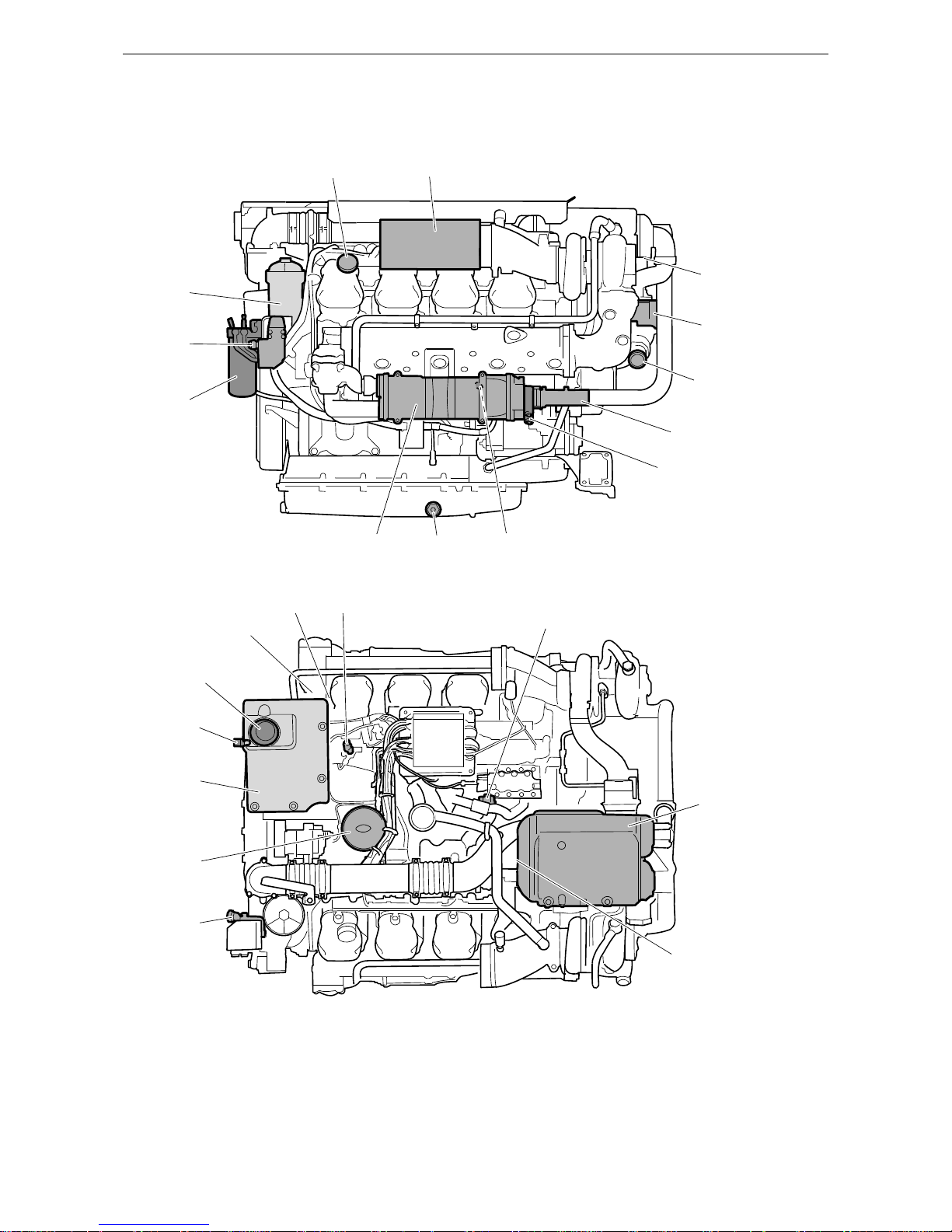
Component identification
12
11
10
98 7
3
4
5
6
3
21
381 636
1817
16
15
14
13
23
22
21
20
19
381 637
Page 14

Component identification
OPM 360 en-GB 14
© Scania CV AB 2017, Sweden
1.
Oil filler.
2. Air filter.
3. Sacrificial anodes (6).
4. Sea water pump.
5. Sea water intake.
6. Sea water outlet (1 on each side)
7. Valve for draining and filling coolant (1 on
each side behind the heat exchanger).
8. Oil plug.
9. Heat exchanger (1 on each side).
10. Fuel filter.
11. Hand pump for fuel.
12. Oil filter.
13. Expansion tank.
14. Level glass for checking coolant level.
15. Filling coolant.
16. Engine number, stamped into the cylinder
block.
17. Engine data plate.
18. Fuel manifold bleed nipple.
19. Bleed nipple on high pressure pump.
20. Charge air cooler.
21. Holes for draining condensation in charge air
cooler (2 off on the underside).
22. Oil dipstick.
23. Centrifugal oil cleaner.
Note:
The two water separating prefilters for the fuel
are located between the fuel tank and engine.
Page 15

OPM 360 en-GB 15
© Scania CV AB 2017, Sweden
Starting and running
Starting and running
Checks before first start
Before the engine is started for the first time, carry out the maintenance items listed under First
start in the maintenance schedule. Check the following (also see Maintenance intervals
):
• Oil level.
• Coolant.
• Fuel level.
• Fluid level in batteries.
• State of battery charge.
• Condition of the drive belt.
Checks before running
Carry out daily maintenance as described in the
maintenance schedule prior to operation. See
Maintenance intervals
.
Starting the engine
WARNING!
Never use starter gas or similar agents to help
start the engine. This can cause an explosion in
the intake manifold and possible injury.
Only start the engine in a well ventilated area.
When the engine is run in an enclosed space,
there must be effective devices to extract exhaust
gases and crankcase gases.
IMPORTANT!
The starter motor must only be cranked twice for
30 seconds at a time. After that, it must rest for at
least 5 minutes before the next attempt to start it.
For environmental reasons the Scania engine has
been developed to be started with a low fuel feed.
Using unnecessarily large amounts of fuel when
starting the engine always results in emissions of
unburnt fuel.
1. Open the fuel cock if fitted.
2. Disengage the engine.
3. If the engine has a battery master switch:
Switch on the power by means of the battery
master switch.
4. Start the engine.
If the fuel tank has been run dry or if the engine
has not been used for a long time, bleed the fuel
system. See the section Bleeding the fuel system
.
Page 16

OPM 360 en-GB 16
© Scania CV AB 2017, Sweden
Starting and running
Starting at low temperatures
Take the local environmental requirements into
account. Use a fuel heater and engine heater to
avoid starting problems and white smoke.
Scania recommends that an engine heater should
be used if the engine will be used at temperatures
below -10°C (14°F).
A low engine speed and a moderate load on a
cold engine limits white smoke, gives better
combustion and warms up the engine more
quickly than warming it up with no load.
Avoid running it longer than necessary at idling
speed.
Running
Check instruments and warning lamps at regular
intervals.
Engine speed range
The engine operating speed range is between low
idling and the nominal engine speed. The nominal engine speed is indicated on the engine data
plate. Low idling can be set between 500 and
1,050 rpm.
Limp home mode
If there is a fault in the normal throttle opening or
if CAN communication is interrupted, the following emergency operation option is provided:
A CAN fault or throttle opening fault in an allspeed engine (both signal and idling switch):
• The throttle opening value is 0% and the engine is running at normal idling speed.
• The throttle opening value is 0% and the engine is running at raised idling speed (750
rpm) if this function is activated.
Throttle opening fault, but the idling switch is
working:
• The throttle opening value can be increased
slowly between 0 and 50% by using the idling
switch.
CAN fault:
• The engine is switched off if the shutdown
function is activated.
Driving at high altitude
When driving at high altitudes engine power is
reduced automatically due to the lower oxygen
content in the air. It is then not possible to run the
engine at maximum power.
The engine must not be run at an altitude of more
than 1,000 metres. Contact Scania if the operating conditions deviate from these.
Page 17

OPM 360 en-GB 17
© Scania CV AB 2017, Sweden
Starting and running
Coolant temperature
IMPORTANT!
An excessive coolant temperature can cause engine damage.
Normal coolant temperature during operation is
approximately 94°C (200°F).
The alarm levels are set in the engine control
unit. The default setting for the lowest and highest limit values for high coolant temperature are
95 °C (203 °F) and 105°C (221°F) respectively.
The high coolant temperature alarm has the following functions:
• Alarm only.
• Alarm and torque reduction at the lowest limit value.
• Alarm at the lowest limit value and engine
shutdown at the highest limit value.
• Alarm, torque reduction at the lowest limit
value and engine shutdown at the highest limit value.
• Alarm at the lowest limit value and engine
shutdown at the highest limit value with the
possibility of engine shutdown override control.
• Alarm, torque reduction at the lowest limit
value and engine shutdown at the highest limit value, with the possibility of engine shutdown override control.
If run for extended periods under an extremely
light load, the engine may have difficulty in
maintaining the coolant temperature. At an increased load the coolant temperature rises to the
normal value.
Oil pressure
Normal oil pressure during operation is 3-6 bar
(43.5-87 psi). The lowest permitted oil pressure
when idling is 0.7 bar (10.2 psi).
The engine management system issues an alarm
at the following levels:
• At an engine speed below 1,000 rpm and an
oil pressure below 0.7 bar (10.2 psi).
• At an engine speed above 1,000 rpm and an
oil pressure below 2.5 bar (36.3 psi) for
longer than 3 seconds.
The incorrect oil pressure alarm has the following functions:
• Alarm only.
• Alarm and torque reduction by 30%.
• Alarm and engine shutdown.
• Alarm and engine shutdown override control.
Note:
High oil pressure (above 6 bar/87 psi) is normal
if the engine is cold when started.
Charging indicator lamp
If the lamp comes on during operation: Check
and adjust the alternator drive belt according to
the instructions in the section Checking the drive
belt.
If the charging indicator lamp is still on, this
could be due to an alternator fault or a fault in the
electrical system.
Belt transmission
When the belt transmission is new, it may make
a squeaking noise when running. The noise is
normal and disappears after 50-100 hours of operation. The noise does not affect the service life
of the belt transmission.
Page 18

OPM 360 en-GB 18
© Scania CV AB 2017, Sweden
Starting and running
Engine shutdown
IMPORTANT!
There is risk of post boiling and of damage to the
turbocharger if the engine is switched off without cooling. The power must not be switched off
before the engine has stopped.
Note:
The battery voltage must remain on for a few
seconds after the 15 voltage is switched off so
that the control units can store the values and
switch to standby mode.
10 prohibited engine shutdowns will cause a
torque reduction (70% of fuel quantity). Reset
the engine by switching it off correctly once.
1. Run the engine without a load for a few min-
utes if it has been run continuously with a
heavy load.
2. Switch off the engine.
Checks after running
WARNING!
Block the starting device when working on the
engine. If the engine starts unexpectedly, there is
a serious risk of injury.
There is always a risk of sustaining burns when
an engine is hot. Particularly hot parts are engine
manifolds, turbochargers, oil sumps, as well as
hot coolant and oil in pipes and hoses.
IMPORTANT!
Check the coolant level following the first start.
Top up with coolant as necessary.
1. Check that the power supply has been cut.
2. Top up the fuel tank. Make sure that the filler
cap and the area round the filler opening are
clean to avoid contamination of the fuel.
3. If there is a risk of freezing, the cooling sys-
tem must contain enough glycol. See the section Coolant resistance to cold
.
4. If the temperature is below 0°C (32°F): Pre-
pare for the next start by connecting the engine heater (if fitted).
Page 19

Maintenance
OPM 360 en-GB 19
© Scania CV AB 2017, Sweden
Maintenance
The maintenance programme covers a number of
points that are divided into the following sections:
• Lubrication system.
• Air cleaner.
• Cooling system.
• Fuel system.
•Other.
WARNING!
Block the starting device when working on the
engine. If the engine starts unexpectedly, there is
a serious risk of injury.
There is always a risk of sustaining burns when
an engine is hot. Particularly hot parts are engine
manifolds, turbochargers, oil sumps, as well as
hot coolant and oil in pipes and hoses.
The maintenance programme includes the following:
• S maintenance: Minimum basic maintenance.
• M maintenance: More extensive maintenance.
• L maintenance: Almost all maintenance
items.
• XL maintenance: All maintenance items.
During a period, the sequence is S-M-S-L-S-MS-L-S-M-S-XL.
XL
6000
S
5500
M
5000
S
4500
L
4000
S
3500
M
3000
S
2500
L
2000
S
1500
M
1000
S
500
313 153
Page 20

Maintenance
OPM 360 en-GB 20
© Scania CV AB 2017, Sweden
IMPORTANT!
On delivery a Scania engine is optimised for its
application. However, regular maintenance is
necessary to:
• prevent unplanned stops
• extend the service life of the engine
• maximise the long-term emission performance of the engine
• give the best possible operating economy.
Page 21

Maintenance
OPM 360 en-GB 21
© Scania CV AB 2017, Sweden
Maintenance intervals
Daily First time at Interval (hours) At least
first start 500 500 1,000 2,000 6,000 annual-lyevery 5
years
RSMLXL
Lubrication system
Checking oil level XX
Changing the oil XXXXX X
Cleaning the centrifugal oil
cleaner
XXXXX X
Renewing the oil filter XXXXX X
Air cleaner
Reading the vacuum indicator X XXXXX
Renewing the filter element XX X
Renewing the safety cartridge XX X
Renewing an air filter with a
non-renewable element
XX X
Cooling system
Checking coolant level X X XXXXX
Checking coolant antifreeze
and corrosion protection
XXXX
Checking sacrificial anodes XXXXX X
Checking the sea water pump
impeller
XXXXX X
Changing the coolant and
cleaning the cooling system
XX
Fuel system
Checking fuel level XX
Draining the water separating
prefilter
XXXXX
Renewing the fuel filters XXXXX X
Miscellaneous
Checking the drive belt XXXXX
Checking for leaks X XXXXX
Checking and adjusting the
valve clearance
XXX
Page 22

Lubrication system
OPM 360 en-GB 22
© Scania CV AB 2017, Sweden
Lubrication system
Oil grade
Scania LDF stands for the Scania Long Drain
Field test standard. Scania LDF oils have been
carefully selected after extensive testing. The approval is only granted to the highest quality engine oils available on the market.
The engine oil must fulfil the following quality
requirements:
• ACEA E5/API CI-4.
• ACEA E7/API CI-4 +.
• For engines not run on low-sulphur fuel, the
TBN (Total Base Number) should be at least
12 (ASTM D2896).
• Oils with a low ash content (ACEA E9/API
CJ4) are not recommended.
Check with your oil supplier that the oil meets
these requirements.
If the engine is used in areas of the world where
engine oil with ACEA or API classification is
not available, the oil grade must be measured in
actual operation. In this case contact the nearest
Scania workshop.
For operation at extremely low outdoor temperatures: Consult your nearest Scania representative
on how to avoid starting difficulties.
Recommended engine oil
Scania Oil LDF-3
Scania Oil LDF-2
Scania Oil LDF
Scania Oil E7
Viscosity class Outdoor temperature
SAE 20W-30 -15°C (5°F) - +30°C (86°F)
SAE 30 -10°C (14°F) - +30°C (86°F)
SAE 40 -5°C (23°F) - +45°C (113°F)
SAE 50 0°C (32°F) - +45°C (113°F)
SAE 5W-30 < -40°C (-40°F) - +30°C (86°F)
SAE 10W-30 -25°C (-13°F) - +30°C (86°F)
SAE 15W-40 -20°C (-4°F) - +45°C (113°F)
Page 23

Lubrication system
OPM 360 en-GB 23
© Scania CV AB 2017, Sweden
Oil grade labels
When changing oil it is important to use the correct engine oil grade. The oil filler cap must
therefore be clearly marked with a label for the
oil grade that is required.
If the label is missing or if the engine oil grade is
changed, a new label must be fitted.
Parts
Oil grade Colour Part number
Scania LDF-3 Red 2 296 066
Scania LDF-2 Blue 2 296 064
Scania LDF Grey 2 296 071
ACEA E7 White 2 296 065
Scania Low Ash Green 2 296 067
Scania Bioethanol Black 2 296 068
Scania BEO-2 Orange 2 296 070
ACEA E9 - 2 296 069
353 114
Oil filler label.
Page 24
Lubrication system
OPM 360 en-GB 24
© Scania CV AB 2017, Sweden
Oil analysis
To be able to extend the oil change intervals using an oil analysis, Scania LDF-2 and LDF-3 oils
must be used. Most oil companies offer analysis
of the engine oil.
The following conditions must remain fulfilled when the oil is changed:
• Viscosity at 100°C (212°F): max. ±20% of
original value of the fresh oil.
• TBN (in accordance with ASTM D4739): >
3.5.
• TBN (in accordance with ASTM D4739): >
TAN (in accordance with ASTM D664).
• Soot (in accordance with DIN 51452): < 3%.
Such analysis measures the oil's TBN (Total
Base Number), TAN (Total Acid Number), fuel
dilution, water content, viscosity and the quantity of particles and soot in the oil. A suitable oil
change interval is determined based on a series
of oil analyses.
If the conditions are changed, a new series of oil
analyses must be carried out to establish new oil
change intervals.
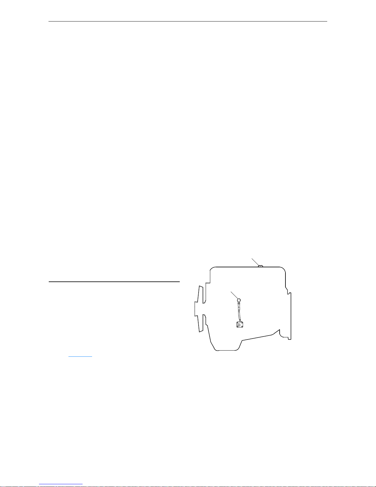
Checking oil level
Note:
Leave the engine off for at least 7 minutes before
you check the oil level.
1. Remove the oil dipstick and check the oil
level. The correct level is between the minimum and maximum marks on the oil dipstick.
2. Fill with more oil via the oil filler if the oil
level is at or below the minimum mark.
For information on the correct oil type, see the
section Oil grade
.
312 506
2
1
Page 25
Lubrication system
OPM 360 en-GB 25
© Scania CV AB 2017, Sweden
Changing the oil
WARNING!
Hot oil can cause burns and skin irritation. Wear
protective gloves and eye protection when
changing hot oil. Make sure that there is no pressure in the lubrication system before changing
the oil. The oil filler cap must always be in place
when starting and running the engine to prevent
oil being ejected.
Note:
Change oil more often if the engine is subjected
to particularly demanding operation, such as a
dusty environment, or if deposits in the centrifugal oil cleaner are thicker than 28 mm (1.1 in).
Renew the oil filter and clean the centrifugal oil
cleaner when changing oil.
Environment
Use a suitable container. Used oil must be disposed of as specified in national and international laws and regulations.
1. Unscrew the oil plug and drain the oil when
the engine is hot. In certain engines the oil is
pumped out by means of a bilge pump. When
draining via the valve, the oil should be hot.
Alternatively, use a pump. This so that draining occurs more quickly.
2. Clean the magnet on the oil plug.
3. Refit the oil plug.
4. Fill with oil.
5. Check the level on the oil dipstick.
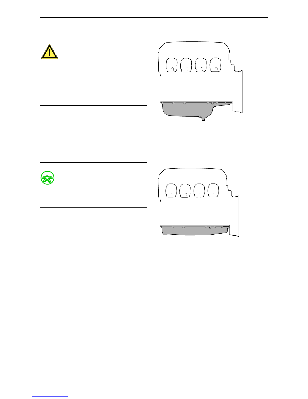
345 618
Oil volume for oil sump with deep front:
Min. 40 litres (10.5 US gallons).
Max. 48 litres (12.6 US gallons).
346 279
Oil capacity for low oil sump:
Min. 29 litres (7.6 US gallons).
Max. 37 litres (9.7 US gallons).
Page 26

Lubrication system
OPM 360 en-GB 26
© Scania CV AB 2017, Sweden
Maximum angles of inclination during operation
Maximum permissible angles of inclination during operation vary, depending on the type of oil
sump. See illustration.
25°
25°
30° 30°
25°
25°
30°30°
343 840
Page 27

Lubrication system
OPM 360 en-GB 27
© Scania CV AB 2017, Sweden
Cleaning the centrifugal oil
cleaner
Tool
WARNING!
The oil may be hot. Carefully remove the cover
from the centrifugal oil cleaner.
Note:
Always use genuine Scania parts during maintenance of the centrifugal oil cleaner. This will ensure that the centrifugal oil cleaner continues to
function.
When the centrifugal oil cleaner is cleaned, there
should be some dirt deposits in the rotor cover.
This indicates that the rotor is working. If the rotor cover is clean, in other words the rotor is not
working, the cause must be established immediately.
If the dirt deposits exceed 28 mm (1.1 in) at the
recommended maintenance intervals, the rotor
cover should be cleaned more often.
1. Remove the centrifugal oil cleaner.
2. Clean the cover. Unscrew the nut securing
the outer cover.
3. Let the oil run out from the rotor.
4. Lift out the rotor. Wipe off the outside. Undo
the rotor nut and unscrew it about 1.5 turns to
protect the bearing.
Note:
Take care not to damage the rotor shaft.
Designation Illustration
Torque wrench 2-20 Nm with exchangeable ratchet
head
364 731
x 1.5
133 315
Page 28

Lubrication system
OPM 360 en-GB 28
© Scania CV AB 2017, Sweden
5.
If the rotor nut is difficult to get loose, turn
the rotor upside down and fasten the rotor nut
in a vice. Turn the rotor anti-clockwise
1.5 turns by hand or use an M20 nut, see illustration.
IMPORTANT!
The rotor must not be put in a vice. Never strike
the rotor cover. This may cause damage resulting
in imbalance.
6. Remove the rotor cover by holding the rotor
in both hands and tapping the rotor nut
against the table. Never strike the rotor directly as this may damage its bearings.
7. Remove the strainer from the rotor cover. If
the strainer is stuck, insert a screwdriver between the rotor cover and strainer and carefully prise them apart.
x 1.5
M20
Page 29

Lubrication system
OPM 360 en-GB 29
© Scania CV AB 2017, Sweden
8.
Remove the paper insert and scrape away
any remaining dirt deposits inside the rotor
cover. If the deposits are thicker than 28 mm
(1.1 in), the centrifugal oil cleaner must be
cleaned more often.
9. Wash the parts.
10. Inspect the 2 nozzles on the rotor. Ensure that
they are not blocked or damaged. Renew any
damaged nozzles.
11. Check that the bearings are undamaged. Re-
new damaged bearings.
12. Fit a new paper insert inside the rotor cover.
333 044
333 037
Page 30

Lubrication system
OPM 360 en-GB 30
© Scania CV AB 2017, Sweden
13.
Fit the strainer onto the rotor.
14. Fit a new O-ring by sliding it over the strain-
er.
15. Refit the rotor cover. Ensure that the O-ring
is not outside the edges.
16. Tighten the rotor nut by hand.
17. Check that the rotor shaft is not damaged or
loose.
If the rotor shaft needs renewing, the renewal
procedure is described in the Workshop
Manual, which can be ordered from a Scania
dealer or directly from Scania.
18. Refit the rotor and rotate it by hand to check
that it rotates easily.
Note:
Take care not to damage the rotor shaft.
313 612
Page 31

Lubrication system
OPM 360 en-GB 31
© Scania CV AB 2017, Sweden
19.
Fit a new O-ring in the cover. Refit the cover
and tighten the lock nut. Tightening torque
15 Nm (11 lb/ft).
IMPORTANT!
To reduce the risk of oil leakage it is important to
tighten the cover to the correct tightening torque.
Operational testing of the
centrifugal oil cleaner
Operational testing need only be carried out if it
is suspected that the centrifugal oil cleaner is
malfunctioning. For example, if the dirt deposit
is abnormally small given the distance driven.
The rotor rotates very fast and should continue to
turn when the engine has stopped.
1. Run the engine until it reaches normal oper-
ating temperature.
2. Turn off the engine and listen for the sound
from the rotor. Use your hand to feel if the
filter housing is vibrating.
3. If the filter housing is not vibrating, disman-
tle and check the centrifugal oil cleaner.
313 611
369 844
Page 32

Lubrication system
OPM 360 en-GB 32
© Scania CV AB 2017, Sweden
Renewing the oil filter
Tool
IMPORTANT!
Clean the centrifugal oil cleaner at the same time
as you change the oil filter. Otherwise, the oil filter will be blocked and resistance in the filter will
increase. If this happens, an overflow valve in
the filter retainer opens and lets the oil pass without being filtered.
The engine must not be run without a filter element in the oil filter. There is a risk of engine
damage caused by particles and by the oil pressure being too low.
1. Unscrew the filter cover using the socket.
IMPORTANT!
Do not use an adjustable spanner or other open
tool, as there is a risk of damaging the filter cover.
2. Lift out the filter housing cover with filter el-
ement. The filter housing will drain automatically once the filter has been removed.
3. Undo the old filter from the cover by careful-
ly bending it to one side.
4. Fit a new O-ring on the cover. Lubricate the
O-ring with engine oil.
5. Press a new filter into the snap fastener in the
cover and tighten the filter cover to 25 Nm
(18 lbf/ft).
6. Make sure the oil filter drain has emptied the
oil from the filter housing. Screw on the filter
cover firmly with the socket.
7. Start the engine and inspect the filter housing
for leaks.
Designation Illustration
Hexagon socket, 1/2",
36 mm
118 268
7
6
5
4
3
2
1
381 921
1. Cover.
2. O-ring.
3. Filter element.
4. Pipe.
5. Filter housing.
6. Flange screw.
7. Gasket.
Page 33

Air cleaner
OPM 360 en-GB 33
© Scania CV AB 2017, Sweden
Air cleaner
Reading the vacuum indicator
If the indicator's red plunger is fully visible, renew the air cleaner filter element following the
instructions below.
Renewing the filter element
WARNING!
Never start the engine without the air filter being
in place. If you do, this could cause injury and severe engine damage.
IMPORTANT!
Renew the filter element earlier than the maintenance interval if the indicator shows red.
There is always a risk that the filter element will
be damaged when it is cleaned.
The filter element must not be cleaned in water
or be blown clean with compressed air.
1. Remove the cover from the air cleaner.
2. Renew the filter element.
3. Insert a torch into the element and check
from the outside that there are no holes or
cracks in the filter paper.
4. Assemble the air cleaner.
5. Reset the vacuum indicator by pressing the
button.
A B
336 100
A. Vacuum indicator.
B. Filter element.
326 671
Resetting the vacuum indicator.
Page 34

Air cleaner
OPM 360 en-GB 34
© Scania CV AB 2017, Sweden
Renewing the safety cartridge
WARNING!
Never start the engine without the air filter being
in place. If you do, this could cause injury and severe engine damage.
IMPORTANT!
When you renew the safety cartridge, take great
care to ensure that no dirt or other impurities get
into the engine. Do not remove the safety cartridge unnecessarily.
1. Remove the cover from the air cleaner.
2. Remove the filter element.
3. Remove the safety cartridge.
4. Fit a new safety cartridge from Scania.
5. Renew or clean the filter element.
6. Check the condition of the O-ring. Renew
the O-ring if it is damaged or hard.
7. Assemble the air cleaner. Ensure that the O-
ring is not outside the edges.
Renewing an air filter with a
non-renewable element
IMPORTANT!
If the engine has air filters with a non-renewable
Scania element, they should be renewed instead
of cleaned.
4
2
3
1
361 380
Air cleaner.
1. Cover.
2. Filter element.
3. Safety cartridge.
4. O-ring.
325 166
Air filter with a non-renewable element.
Page 35

OPM 360 en-GB 35
© Scania CV AB 2017, Sweden
Cooling system
Cooling system
Coolant
WARNING!
Ethylene glycol can be fatal if ingested and can
cause skin irritation and eye damage.
Note:
The coolant should be changed when the cooling
system is cleaned: every 6,000 hours or at least
every 5 years. See the section Changing the cool-
ant and cleaning the cooling system.
The coolant has several characteristics which are
important for the operation of the cooling system:
• Corrosion inhibitor.
• Antifreeze.
• Increases the boiling point.
Scania recommends that the coolant used is a
mixture of water with antifreeze and corrosion
inhibitor (ethylene glycol). The coolant should
always contain 35-55% by volume of antifreeze
and corrosion inhibitor so that the coolant has the
correct properties for the cooling system to work.
Coolant resistance to cold
The following example shows coolant properties
with 30 percent by volume of antifreeze and corrosion inhibitor:
• Ice slush starts to form at -16°C (3°F).
• At -30°C (-22°F), there is a risk of cooling
system malfunction.
• There is no risk of damage by freezing with a
minimum antifreeze and corrosion inhibitor
content of 35 percent by volume.
The chart depicts coolant properties at different
percents of antifreeze and corrosion inhibitor
concentration by volume.
Curve A: Ice formation starts (ice slush)
Curve B: Damage by freezing occurs
Area 1: Safe area
Area 2: Malfunctions may occur (ice
slush)
Area 3: Risk of damage by freezing
312 505
2
1
3
°C BA
-50
-40
-30
-20
-16
-10
0
100 20304050%
Page 36

OPM 360 en-GB 36
© Scania CV AB 2017, Sweden
Cooling system
Antifreeze and corrosion protection concentration table, litres
35% by volume of Scania antifreeze provides
sufficient protection against corrosion.
Example:
• The total volume of the cooling system is 40
litres.
• The measured concentration of ethylene glycol is 35% by volume (freezing point -21°C).
According to the table there are 14 litres of
ethylene glycol in the cooling system.
• The required concentration of ethylene glycol
is 45% by volume (freezing point -30°C). According to the table, 18 litres of ethylene glycol are required in the cooling system.
• Since there are already 14 litres in the cooling
system, 4 litres of ethylene glycol must be
added to the cooling system (18 - 14 = 4 litres).
Adequate protection against corrosion
Volume of ethylene glycol (%) 35 40 45 50 60 Cooling system volume
Ice slush forms (°C) -21 -24 -30 -38 -50 (litres)
Volume of ethylene glycol (litres)
11 12 14 15 18 30
14 16 18 20 24 40
18 20 23 25 30 50
21 24 27 30 36 60
25 28 32 35 42 70
28 32 36 40 48 80
32 36 41 45 54 90
35 40 45 50 60 100
39 44 50 55 66 110
42 48 54 60 72 120
46 52 59 65 78 130
49 56 63 70 84 140
53 60 68 75 90 150
56 64 72 80 96 160
60 68 77 85 102 170
63 72 81 90 108 180
67 76 86 95 114 190
70 80 90 100 120 200
Page 37

Cooling system
OPM 360 en-GB 37
© Scania CV AB 2017, Sweden
Antifreeze and corrosion protection concentration table, US gallons
35% by volume of Scania antifreeze provides
sufficient protection against corrosion.
Example:
• The total volume of the cooling system is
10.6 US gallons.
• The measured concentration of ethylene glycol is 35% by volume (freezing point -6 °F).
According to the table there are
3.7 US gallons of ethylene glycol in the cooling system.
• The required concentration of ethylene glycol
is 45% by volume (freezing point -22 °F). According to the table, 4.8 US gallons of ethylene glycol are required in the cooling system.
• Since the cooling system already contains
3.7 US gallons, fill another 1.1 US gallons of
ethylene glycol in the cooling system (4.8 -
3.7 = 1.1 US gallons).
Adequate protection against corrosion
Volume of ethylene glycol (%) 35 40 45 50 60 Cooling system volume
Ice slush forms (°F) -6 -11 -22 -36 -58 (US gallons)
Volume of ethylene glycol (US gallons)
2.9 3.2 3.7 4 4.8 7.9
3.74.24.85.36.3 10.6
4.85.36.16.67.9 13.2
5.56.37.17.99.5 15.9
6.6 7.4 8.5 9.2 11.1 18.5
7.4 8.5 9.5 10.6 12.7 21.1
8.5 9.5 10.8 11.9 14.3 23.8
9.2 10.6 11.9 13.2 15.9 26.4
10.3 11.6 13.2 14.5 17.4 29.1
11.1 12.7 14.3 15.9 19 31.7
12.2 13.7 15.6 17.2 20.6 34.3
12.9 14.8 16.6 18.5 22.2 37
14 15.9 18 19.8 23.8 39.6
14.8 16.9 19 21.1 25.4 42.3
15.9 18 20.3 22.5 26.9 44.9
16.6 19 21.4 23.8 28.5 47.6
17.7 20.1 22.7 25.1 30.1 50.2
18.5 21.1 23.8 26.4 31.7 52.8
Page 38

OPM 360 en-GB 38
© Scania CV AB 2017, Sweden
Cooling system
Antifreeze and corrosion protection
products
Only Scania coolant or other products that Scania has tested to provide proper antifreeze and corrosion protection, may be used in Scania
engines. Products that do not satisfy the requirements for use in a Scania engine can result in
faults in and damage to the cooling system. This
can lead to the invalidation of Scania's warranty
for faults and damage caused by the use of inappropriate coolant.
The antifreeze and corrosion protection products
used in Scania engines should be of the ethylene
glycol type.
Below is a list of Scania antifreeze and corrosion
protection products.
Scania concentrate
Coolant with antifreeze and corrosion inhibitor
in the form of a concentrate.
Scania Ready Mix
Coolant with antifreeze and corrosion inhibitor
Ready Mix 50/50.
Part No. Volume Volume
litres US gallons
1 894 323 5 1.3
1 894 324 20 5.3
1 894 325 210 55
1 894 326 1,000 264
Part No. Volume Volume
litres US gallons
1 921 955 5 1.3
1 921 956 20 5.3
1 921 957 210 55
1 896 695 1,000 264
Checking coolant level
WARNING!
Do not open the coolant filler cap in the expansion tank if the engine is hot. Hot coolant and
steam may spray out and cause burns.
If the cap has to be opened do it slowly to release
the pressure before removing the cap. Wear protective gloves as the coolant is still very hot.
IMPORTANT!
It is not permissible to top up large amounts of
coolant via the expansion tank. Filling via the expansion tank leads to air locks in the cooling system which can lead to e.g. cavitation damage to
the coolant pump shaft seal. If a large amount of
coolant needs to be added, follow the instructions in the section Filling coolant
.
Only pour pre-mixed coolant into the cooling
system.
1. Check the coolant level through the sight
glass on the expansion tank.
2. Top up with coolant as necessary.
Page 39

OPM 360 en-GB 39
© Scania CV AB 2017, Sweden
Cooling system
Checking coolant antifreeze
and corrosion protection
Tool
IMPORTANT!
Use only pure fresh water that is free from particles, sludge and other impurities.
1. Pour a small amount of coolant into a con-
tainer and check that the coolant is pure and
clear.
2. Change the coolant if it is contaminated or
cloudy.
3. Measure the antifreeze content with a refrac-
tometer.
The following rules apply to ethylene glycolbased coolant:
• The antifreeze and corrosion inhibitor content
must be minimum 35 percent by volume for
corrosion protection to be sufficient.
• An antifreeze and corrosion inhibitor content
greater than 55 percent by volume impairs the
ability to protect against frost.
• If ice forms in the coolant, there are disruptions initially, but there is no immediate risk
of damage. The engine should not be subjected to heavy loads when ice starts to form.
Designation Illustration
Refractometer
305 523
138008
Page 40

Cooling system
OPM 360 en-GB 40
© Scania CV AB 2017, Sweden
Checking sacrificial anodes
1. Drain the sea water circuit. See the section
Draining the sea water circuit
.
2. Check the sacrificial anodes and scrape off
all loose material from them.
3. Renew the sacrificial anode if less than half
of it is left. A new sacrificial anode is 60 mm
long with a diameter of 17 mm.
4. Renew the gasket when fitting.
5. If the sacrificial anodes are very corroded,
the inspection intervals must be reduced.
Checking the sea water pump
impeller
1. Drain the sea water circuit. See the section
Draining the sea water circuit
.
2. Check that the vanes of the impeller are not
heavily splintered or damaged.
329 967
Position of sacrificial anodes.
361 639
Sea water pump cover.
Page 41

Cooling system
OPM 360 en-GB 41
© Scania CV AB 2017, Sweden
Renewing the sea water pump impeller
Special tool
Note:
If the impeller must be renewed frequently, the
cleaning of the sea water needs to be improved.
There should be a spare impeller on board.
The impeller can be deformed during extended
periods of inactivity. Renew the impeller before
starting or remove the impeller before longer periods of stoppage.
1. Thread the puller stud into the rubber impel-
ler using an internal hexagon key until the
stud reaches the bottom.
Note:
Note the direction of rotation of the impeller
vanes.
2. Screw the puller into the rubber impeller us-
ing the handle until it reaches the stud. Then
continue to screw until the impeller comes
loose.
3. Unscrew the stud.
IMPORTANT!
Check that the direction of rotation of the impeller vanes is the same as during removal.
4. Lubricate the impeller with pump grease and
then fit it using a rubber mallet.
5. Fit the sea water pump cover. Tightening
torque 7.5 Nm (5.5 lb/ft).
Number Designation Illustration
2 443 680 Puller
360 276
361 638
361 639
Sea water pump cover.
Page 42

Cooling system
OPM 360 en-GB 42
© Scania CV AB 2017, Sweden
Changing the coolant and
cleaning the cooling system
Draining coolant
Special tool
WARNING!
Do not open the coolant filler cap in the expansion tank if the engine is hot. Hot coolant and
steam may spray out and cause burns. If the cap
has to be opened do it slowly to release the pressure before removing the cap.
Use protective gloves as coolant can cause irritation if it comes in contact with the skin. Hot coolant can also cause scalding.
Environment
Use a suitable container. Used coolant must be
disposed of as specified in national and international laws and regulations.
1. Open the expansion tank cap.
2. Position the hose from the coolant pump in
an empty container.
3. Connect the pump to the draining nipple in
the cylinder block. See illustration.
4. Connect the pump's 2 cable terminals to the
battery's negative and positive terminal.
Make sure that the drainage starts. If the
drainage does not start: Change the position
of the cable terminals.
5. Repeat the procedure at the cooling system's
lowest drainage point. The location of the
lowest drainage point on the engine may differ depending on engine application.
Number, designation
2 443 679, coolant
pump
360 625
360 707
Drain nipple in the cylinder block (behind the heat
exchanger).
Page 43

Cooling system
OPM 360 en-GB 43
© Scania CV AB 2017, Sweden
Draining the sea water circuit
1. Close the bottom valve on the sea water inlet
and remove the connection pipe on the outlet
from heat exchanger (1).
2. Remove the cover from the sea water pump
to completely drain the pump (2).
The lowest point in the sea water circuit may be
at different points, but it is usually in the sea water pump intake (3).
IMPORTANT!
Plug the connections to prevent dirt ingress into
the engine.
Removing the charge air cooler
When the charge air cooler core needs cleaning,
the charge air cooler must be removed if there is
no space behind it to take out the core.
1. Make sure that the cooling system is com-
pletely drained as described in the previous
section.
2. Unscrew and remove the catwalk, protective
plate and the protective casing.
3
1
2
342 753
Page 44

Cooling system
OPM 360 en-GB 44
© Scania CV AB 2017, Sweden
3.
On the left-hand turbocharger, remove the
hose between the oil mist separator and the
air filter flange. Use a screwdriver to pull out
the lock.
4. Loosen and remove the hose clamps for the
charge air pipe.
5. Remove all sea water pipes to and from the
charge air cooler.
329 313
329 320
352 044
Page 45

Cooling system
OPM 360 en-GB 45
© Scania CV AB 2017, Sweden
6.
Right-hand turbocharger: Remove the Vclamp and the screw for the bracket. Remove
the charge air pipe.
7. Left-hand turbocharger: Remove the V-
clamp and carefully turn the charge air pipe
during removal.
8. Remove the screws securing the charge air
cooler.
9. Lift out the charge air cooler.
329 318
329 341
329 340
Page 46

Cooling system
OPM 360 en-GB 46
© Scania CV AB 2017, Sweden
Cleaning the charge air cooler
The charge air cooler must be removed if there is
no space behind it to take out the cooler cores.
See previous section.
1. Remove the sea water pipes to and from the
charge air cooler. Remove flanges and
charge air pipe from the charge air cooler.
Remove the old gaskets and scrape off any
gasket residue.
2. Remove the screws on the charge air cooler
covers (1) and remove the covers. Mark the
covers so that you can put them back on the
correct side.
3. Press in the cooler core (5) slightly on one
side and pull it out from the other side.
4. Clean the cooler core on the outside with par-
affin-based engine detergent. Remove any
internal deposits using a round rod. Renew
the cooler core if it is damaged.
IMPORTANT!
Do not use caustic soda as this could damage the
aluminium.
5. Renew damaged or hard O-rings (2).
6. Assemble the charge air cooler. Tighten the
M8 screws on the cover to 15 Nm (11 lb-ft).
329 339
1
2
3
4
5
2
2
1
2
362 869
1. Cover.
2. O-rings.
3. Spacer.
4. Charge air cooler housing.
5. Cooler core.
Page 47

Cooling system
OPM 360 en-GB 47
© Scania CV AB 2017, Sweden
Removing the heat exchanger
When the heat exchanger core needs cleaning,
the heat exchanger must be removed.
WARNING!
Use protective gloves as coolant can cause irritation if it comes in contact with the skin. Hot coolant can also cause scalding.
1. Make sure that the cooling system is empty
as described earlier.
2. Remove the sea water pipe between the
charge air cooler and heat exchanger.
3. If the engine has a water-cooled exhaust pipe
bend: Remove the sea water pipe between
the heat exchanger and the exhaust pipe
bend.
4. Remove the coolant pipe with the thermostat
housing cover.
329 322
329 323
Page 48

Cooling system
OPM 360 en-GB 48
© Scania CV AB 2017, Sweden
5.
Remove the coolant pipe from the heat exchanger.
6. Remove the screws on the heat exchanger
and the 2 upper screws on the exhaust manifold bracket.
7. Remove the heat exchanger by holding it in
the bracket, moving the heat exchanger
slightly to the side and removing it.
329 324
329 325
329 326
Page 49

Cooling system
OPM 360 en-GB 49
© Scania CV AB 2017, Sweden
Cleaning the heat exchanger
1. Remove the screws on the heat exchanger
covers (1) and remove the covers. Mark the
covers so that you can put them back on the
correct side.
2. Press in the cooler core (5) slightly on one
side and pull it out from the other side.
3. Clean the cooler core on the outside with par-
affin-based engine detergent. Remove any
internal deposits using a round rod. Renew
the cooler core if it is damaged.
IMPORTANT!
Do not use caustic soda as this could damage the
aluminium.
4. Renew damaged or hard O-rings (3).
5. Assemble the heat exchanger. Tighten the
M8 screws on the cover to 15 Nm (11 lb-ft).
1
2
3
4
3
5
1
362 870
1. Cover.
2. Spacer.
3. O-rings.
4. Heat exchanger housing.
5. Cooler core.
Page 50

Cooling system
OPM 360 en-GB 50
© Scania CV AB 2017, Sweden
Fitting the heat exchanger
1. Fit the heat exchanger by holding it in the ex-
haust manifold bracket, moving it slightly to
the side and fitting it.
2. Fit all screws by hand and then tighten them.
Tightening torque 50 Nm (37 lb/ft).
3. Lubricate and fit the coolant pipe from the
heat exchanger. Angle the pipe from the thermostat housing inwards and push it onto the
connection.
329 327
329 325
329 328
12
Page 51

Cooling system
OPM 360 en-GB 51
© Scania CV AB 2017, Sweden
4.
Fit the coolant pipe with the thermostat housing cover.
5. Fit the sea water pipe between the charge air
cooler and heat exchanger.
6. If the engine has a water-cooled exhaust pipe
bend: Fit the sea water pipe between the heat
exchanger and the exhaust pipe bend.
329 323
329 322
Page 52

Cooling system
OPM 360 en-GB 52
© Scania CV AB 2017, Sweden
Fitting the charge air cooler
1. Fit the charge air cooler. Tighten the 4
screws to 50 Nm (37 lb-ft).
2. Carefully fit the charge air pipe from the left-
hand turbocharger and tighten the V-clamp
to 20 Nm (15 lb-ft).
3. Fit the charge air pipe from the left-hand tur-
bocharger. Fit the V-clamp first and then the
screw on the bracket.
4. Fit the sea water pipe from the sea water
pump, first to the charge air cooler (the inner
pipe) and then from the charge air cooler to
the heat exchanger (the outer pipe).
329 341
329 318
352 044
Page 53

Cooling system
OPM 360 en-GB 53
© Scania CV AB 2017, Sweden
5.
Fit the charge air pipe and the hose clamps.
6. Fit the crankcase ventilation hose.
7. Fit the catwalk:
– Loosely fit the protective plate to the
charge air pipe. Tighten the screws later.
– Fit the protective casing. Tighten the
screws later.
– Fit the catwalk with screws.
– Tighten all screws. The protective plate
and protective casing must be tightened to
a tightening torque of 15 Nm (11 lb-ft).
329 320
329 313
Page 54

OPM 360 en-GB 54
© Scania CV AB 2017, Sweden
Cooling system
Internal: Removing oil and grease
Environment
Use a suitable container. Used coolant must be
disposed of as specified in national and international laws and regulations.
Always fit a new thermostat and a new cover to
the expansion tank after cleaning, as the oil in the
cooling system destroys the seals. If the engine is
equipped with a coolant filter, also renew this filter.
It may be necessary to wash it multiple times if
the cooling system is very dirty. One cause of
contamination can be that oil is lying on top of
the coolant and collecting high up in the cooling
system. If several rinses are needed, this is not
necessarily because work has been carried out
incorrectly. Oil residues often need to be rinsed
repeatedly from the expansion tank and the external heating system to be completely clean.
Repeated washing is more effective and preferable to using higher concentrations of detergent
(max. 10%) or cleaning for a longer period (max
30 minutes).
If only a small amount of dirt has collected in the
expansion tank after cleaning, one extra rinse
and clean of the expansion tank only is usually
sufficient. There is no need to clean the whole
cooling system again.
1. Run the engine until it has reached operating
temperature and then drain the cooling system following the previous description.
2. Remove the thermostats.
3. Fill the cooling system with clean hot water
mixed with detergent 2 479 017. Detergent
2 479 017 must make up 5-10% (depending
on the degree of dirt) of the total coolant volume.
If detergent 2 479 017 is not available, use a
dishwasher detergent for household dishwashers that does not foam. Concentration
1%.
4. Run the engine until it has reached operating
temperature for approximately 20-30 minutes. Remember to switch on the cab heating
system, if one is installed.
5. Drain the cooling system.
6. Fill the cooling system with clean, hot water
and run the engine for about 20-30 minutes.
7. Repeat steps 3-6 if the cooling system is not
clean.
Page 55

Cooling system
OPM 360 en-GB 55
© Scania CV AB 2017, Sweden
8.
Drain the water from the cooling system.
9. If necessary, clean the expansion tank by de-
taching all hoses and rinsing and cleaning
with a degreasing agent and a dishwashing
brush.
Alternatively, dismantle the expansion tank
and clean it with water with 10% of detergent
2 479 017. Fill the expansion tank with the
mixture, shake it around and drain it out. Renew the cover of the expansion tank.
10. Refit the thermostats.
11. Fill the cooling system with new coolant as
described in the next section.
12. Check again whether further dirt or oil has
collected in the expansion tank. Decide
whether it it is necessary to carry out another
full cleaning or whether only rinsing or
cleaning of the expansion tank will suffice.
Internal: Removing deposits
Environment
Use a suitable container. Used coolant must be
disposed of as specified in national and international laws and regulations.
1. Run the engine until it has reached operating
temperature and then drain the cooling system following the previous description.
2. Remove the thermostats.
3. Fill the cooling system with clean, hot water
mixed with radiator detergent which is based
on sulphamic acid and contains dispersing
agents. Follow the manufacturer's instructions for the concentration and cleaning period.
4. Run the engine for the specified time. Re-
member to switch on the cab heating system,
if one is installed.
5. Drain the cooling system.
6. Fill the cooling system with clean, hot water
and run the engine for about 20-30 minutes.
7. Drain the water from the cooling system.
8. Refit the thermostats.
9. Fill the cooling system with new coolant as
described in the next section.
Page 56

OPM 360 en-GB 56
© Scania CV AB 2017, Sweden
Cooling system
Filling coolant
This procedure applies when the cooling system
has been drained and needs to be filled with a
large amount of coolant.
Special tool
WARNING!
Use protective gloves as coolant can cause irritation if it comes in contact with the skin. Hot coolant can also cause scalding.
IMPORTANT!
Mix the coolant as specified in the section headed Coolant
.
Never fill a large amount of cold coolant in a hot
engine. There is great risk of cracks forming in
the cylinder block and cylinder heads.
Do not start the engine until the correct coolant
level has been obtained. If the engine is started
with an insufficient coolant level, it can damage
the coolant pump shaft seal, which leads to coolant leakage.
Number, designation
2 443 679, coolant
pump
360 625
Page 57

Cooling system
OPM 360 en-GB 57
© Scania CV AB 2017, Sweden
1.
Open the expansion tank cap.
2. Connect the coolant pump to the filler nipple
in the cylinder block.
3. Connect the pump's 2 cable terminals to the
battery's negative and positive terminal.
Make sure that the filling starts. If the filling
does not start: Change the position of the cable terminals.
4. Start the engine and run it at idling for
15 minutes.
IMPORTANT!
It is very important that the engine is idling. Engine overspeed could damage the coolant pump
shaft seal, which leads to coolant leakage.
5. Switch off the engine and fill with coolant to
the maximum level through the expansion
tank.
Air pockets may still be left in the cooling system. These will disappear after the engine has
been operated for a period of time. Therefore, the
coolant may need topping up at a later stage.
Finishing work
1. Open the bottom valve on the sea water inlet.
2. Start the engine and check that no leakage
occurs.
3. Check the coolant level and top up the cool-
ant via the expansion tank if necessary.
360 707
Filler nipple in the cylinder block (behind the heat
exchanger).
Page 58

OPM 360 en-GB 58
© Scania CV AB 2017, Sweden
Fuel system
Fuel system
Cleanliness requirements
IMPORTANT!
The whole fuel system is very sensitive to dirt
and even very small particles. Foreign particles
in the system can cause serious malfunctions. It
is therefore very important that everything is as
clean as possible when work is carried out on the
fuel system. Before repair work, the engine must
be washed. If possible, a hot water wash should
be used.
It is strictly forbidden to carry out any machining
work or work with compressed air near an open
fuel system.
Be extra careful and always use clean, lint-free
and dust-free clothes and gloves when working
on the fuel system. Scania recommends using
Tegera 848 gloves.
Clean tools before they are used and do not use
any worn or chrome-plated tools. Material and
flakes of chrome may come off.
Clean connections and the surrounding area before removal. When cleaning, cloths or paper
which shed fibres must not be used. Use clean
and lint free cloths, part number 588 879.
Plug or cover the connections during removal.
Also clean the connections before the components are fitted. Place removed components on a
thoroughly cleaned, dust-free surface. Scania
recommends using a stainless steel bench top,
part number 2 403 296. Cover the components
with a lint free cloth.
Checking fuel level
Check the fuel level and top up with fuel as necessary.
Note:
If the fuel tank has been run dry or if the engine
has not been used for a long time, bleed the fuel
system. See the section Bleeding the fuel system.
Page 59

Fuel system
OPM 360 en-GB 59
© Scania CV AB 2017, Sweden
Draining and renewing the
water separating prefilter
IMPORTANT!
The sensor cable is sensitive. Handle it carefully.
Environment
Use a suitable container. The fuel collected must
be disposed of as specified in national and international laws and regulations.
1. Close the shut-off cock in the fuel pipe and
position a container under the filter.
2. Detach the sensor cables from the contact
housings (1) on the filters.
3. Open the filter drain plugs (2) and allow the
fluid to run down into the container.
4. Unscrew the filters (3) from the filter head
(4).
5. Discard the old filters and use new ones.
6. Lubricate the O-rings on the filters with en-
gine oil.
7. Fill the width of the filters with clean fuel.
8. Screw the filters into position until the O-
rings rest against the filter head. Tighten the
filters another quarter to three quarter turn by
hand.
9. Open the shut-off cock in the fuel pipe and
check that the fuel system is sealed.
10. Connect the sensor cable to the contact hous-
ings on the filters.
11. Bleed the fuel system according to the in-
structions in the Bleeding the fuel system
section.
354 446
1
3
3
4
12 2
Water separating prefilter.
1. Contact housing.
2. Drain plugs.
3. Filter.
4. Filter head.
Page 60

Fuel system
OPM 360 en-GB 60
© Scania CV AB 2017, Sweden
Draining and renewing the
single water separating prefilter
IMPORTANT!
The sensor cable is sensitive. Handle it carefully.
Environment
Use a suitable container. The fuel collected must
be disposed of as specified in national and international laws and regulations.
Before starting work: Close the shut-off cock in
the fuel pipe and position a container under the
filter.
1. Undo the sensor cable from the connector on
the filter bracket.
2. Open the drain tap in the filter cover and let
the fluid run down into the container.
3. Unscrew the filter cover.
4. Unscrew the filter from the filter head.
5. Discard the old filter and use a new filter.
6. Lubricate the O-ring in the filter cover with
engine oil.
7. Screw the filter cover onto the new filter by
hand. Make sure that the drain tap is fully
closed.
8. Lubricate the O-ring on the filter with engine
oil.
9. Fill the width of the filter with clean fuel.
10. Screw the filter into position until the O-ring
rests against the filter head. Tighten the filter
another 1/2 to 3/4 turn by hand.
11. Open the shut-off cock in the fuel pipe and
check that the fuel system is sealed.
12. Screw the sensor cable in the contact housing
onto the filter bracket.
13. Bleed the fuel system according to the in-
structions in the Bleeding the fuel system
section.
2
3
4
1
336 101
1. Sensor cable.
2. Drain tap.
3. Filter cover.
4. Filter.
Page 61

Fuel system
OPM 360 en-GB 61
© Scania CV AB 2017, Sweden
Draining the commutative water separating prefilter
During operation, the rotary control should point
90° towards the filter being used.
Environment
Use a suitable container. The fuel collected must
be disposed of as specified in national and international laws and regulations.
1. Switch off the filter that needs renewing. The
arrow on the rotary control should point towards the filter that should remain active
during renewal.
WARNING!
Be careful that the valve does not pass the closed
position when the engine is in operation. A
closed position can result in the engine stopping.
In marine applications, the engine stopping represents a safety hazard.
2. Remove the cover from the filter housing.
1 2 3 4
376 032
1. Closed; neither filter is active.
2. Both filters are active.
3. Left-hand filter is active.
4. Right-hand filter is active.
377 154
Page 62

Fuel system
OPM 360 en-GB 62
© Scania CV AB 2017, Sweden
3.
Undo the drain plug.
4. Tighten the drain plug when all the water has
emptied.
5. Fill the filter housing with clean fuel.
6. Fit the cover. Tighten the cover screw by
hand.
377 156
377 154
Page 63

Fuel system
OPM 360 en-GB 63
© Scania CV AB 2017, Sweden
Renewing the commutative,
water separating prefilter
During operation, the rotary control should point
90° towards the filter being used.
Environment
Use a suitable container. The fuel collected must
be disposed of as specified in national and international laws and regulations.
1. Switch off the filter that needs renewing. The
arrow on the rotary control should point towards the filter that should remain active
during renewal.
WARNING!
Be careful that the valve does not pass the closed
position when the engine is in operation. A
closed position can result in the engine stopping.
In marine applications, the engine stopping represents a safety hazard.
2. Clean the filter housing externally with a
cloth.
3. Remove the cover from the filter housing.
377 154
Page 64

Fuel system
OPM 360 en-GB 64
© Scania CV AB 2017, Sweden
4.
Remove the filter and fit the new filter.
5. Renew the O-rings in the cover.
6. Lubricate the O-rings with engine oil.
7. Fill the filter housing with clean fuel.
8. Fit the cover. Tighten the cover screw by
hand.
377 155
376 035
377 154
Page 65

Fuel system
OPM 360 en-GB 65
© Scania CV AB 2017, Sweden
Renewing the fuel filter
Environment
Use a suitable container. The fuel collected must
be disposed of as specified in national and international laws and regulations.
1. Clean the exterior of the fuel filter with a
damp cloth.
2. Unscrew the filter.
3. Apply oil to the gasket on the new filter.
4. Screw the filter into place by hand until it
makes contact.
5. Screw a further half turn by hand.
6. Bleed the fuel system according to the in-
structions in the following section.
354 444
Fuel filter.
Page 66

Fuel system
OPM 360 en-GB 66
© Scania CV AB 2017, Sweden
Bleeding the fuel system
Bleeding the fuel system using a
hand pump
Environment
Use a suitable container. The fuel collected must
be disposed of as specified in national and international laws and regulations.
1. Screw up the hand pump handle (1).
2. Attach a clear plastic hose to the bleed nipple
on the fuel filter (2). Let the plastic hose drop
into a container that holds at least 5 litres (1.3
US gallons).
3. Open the bleed nipple on the fuel filter.
4. Pump with the hand pump until fuel comes
out.
5. Close the bleed nipple on the fuel filter.
6. Attach a clear plastic hose to the bleed nipple
on the high pressure pump (3). Let the plastic
hose drop into a container that holds at least
5 litres (1.3 US gallons).
7. Open the bleed nipple on the high pressure
pump and pump the hand pump until fuel
comes out. It will take around 150 pump
strokes.
8. Close the bleed nipple on the high pressure
pump and screw down the hand pump handle.
9. Start the engine. The engine should be easy
to start.
1
2
361 379
1. Hand pump.
2. Fuel filter bleed nipple.
3
361 377
Bleed nipple on high pressure pump.
Page 67

Fuel system
OPM 360 en-GB 67
© Scania CV AB 2017, Sweden
Bleeding the fuel system using a suction tool
Tool
Environment
Use a suitable container. The fuel collected must
be disposed of as specified in national and international laws and regulations.
1. Open the bleed nipple on the high pressure
pump (3) and connect the suction tool to it.
2. Hold the suction tool straight and draw out a
full container of fuel.
3. Once the fuel coming out of the hose is free
of air bubbles, then bleeding is complete.
4. Close the bleed nipple on the high pressure
pump. Remove the hose and suction tool.
5. Start the engine and check that no leakage
occurs.
Designation Illustration
Suction tool for fuel system
337 297
3
361 377
Bleed nipple on high pressure pump.
Page 68

Miscellaneous
OPM 360 en-GB 68
© Scania CV AB 2017, Sweden
Miscellaneous
Checking the drive belt
IMPORTANT!
Refit the drive belt with the same direction of rotation as it had before removal.
1. Check the drive belt thoroughly, particularly
at the idler rollers.
2. Check the drive belt for cracks. Renew the
drive belt if deep cracks have formed.
Note:
Small and shallow cracks are normal and form
after only a few hours of operation. They do not
mean that the drive belt needs to be renewed.
However, if there are many, deep cracks, the
drive belt must be renewed. See the illustrations.
381 628
Drive belt.
106 229
Example of a minor crack in the drive belt. The drive
belt can be refitted.
Page 69

Miscellaneous
OPM 360 en-GB 69
© Scania CV AB 2017, Sweden
3.
Check drive belt wear. Renew the drive belt
if it is too worn. See the illustrations.
381 640
The drive belt has deep cracks and must be renewed.
112 931
The drive belt is starting to become worn, but can be
refitted.
112 932
The belt is worn down to the cord. The drive belt
must be renewed.
Page 70

Miscellaneous
OPM 360 en-GB 70
© Scania CV AB 2017, Sweden
Checking for leaks
IMPORTANT!
If serious leakage occurs, contact your nearest
Scania workshop.
1. Start the engine.
2. Check for leaks in the lubrication, intake,
cooling, fuel, or exhaust system.
3. Tighten or renew leaking connections.
Check the overflow holes which show
whether the O-rings between the cylinder
liners and crankcase are leaking.
Page 71

Miscellaneous
OPM 360 en-GB 71
© Scania CV AB 2017, Sweden
Checking and adjusting the
valve clearance
Special tool
WARNING!
Block the starting device. If the engine starts unexpectedly, there is a serious risk of injury.
IMPORTANT!
The engine must be cold when the work is carried out.
Remember to remove the turning tool from the
flywheel after adjustment.
Note:
Carry out the working without pausing, so that
no step is overlooked.
Carry out a check and adjustment of the valve
clearances one more time after the first 500 hours
of operation. After this, adjustment according to
the regular interval takes place, which is every
2,000 operational hours.
Number Designation Illustration
99 309 Turning tool for rotating the flywheel from below
99 109 Turning tool for rotating the flywheel from above
Other tools
Torque wrench 0-50 Nm
Waterproof felt-tip pen
0.45 and 0.70 mm feeler gauges
Flash light
Mirror
142 238
312 733
Page 72

Miscellaneous
OPM 360 en-GB 72
© Scania CV AB 2017, Sweden
On the flywheel is engraved the reference information UP TDC, DOWN TDC and the angle indications listed in the table below. Depending on
the engine installation and type of flywheel
housing, this information is visible in one of the
windows, either furthest up or furthest down on
the flywheel. See illustration.
Adjust valves according to the table below. Follow the respective column depending on whether
you are reading the engraving on the flywheel in
the lower or the upper window. Start adjustment
at the top of the table.
Valve clearance, specifications
Intake valve 0.45 mm (0.018 in)
Exhaust valve 0.70 mm (0.028 in)
Tightening torques
Lock nut for valves 35 Nm (26 lb/ft)
Reading in the low-
er window
Valve transition on
cylinder
Adjust intake valve
on cylinder
Adjust exhaust
valve on cylinder
Reading in the up-
per window
DOWN TDC (0°) 6 7 and 8 4 and 5 UP TDC (180°)
UP TDC (180°) 7 1 and 5 2 and 6 DOWN TDC (0°)
DOWN TDC (360°) 1 2 and 4 3 and 7 UP TDC (540°)
UP TDC (540°) 4 3 and 6 1 and 8 DOWN TDC (360°)
310 343
Upper and lower window to read the engraving on
the flywheel.
1
2
34
5
6
78
361 378
Order of cylinders.
Page 73

Miscellaneous
OPM 360 en-GB 73
© Scania CV AB 2017, Sweden
1.
Clean the rocker covers and the area around
them.
2. Remove the rocker covers.
3. Use the turning tool appropriate to the instal-
lation of the engine. Tool 99 309 is used to
rotate the flywheel from the underside of the
engine and tool 99 109 is used from the top
side.
4. Start adjusting one cylinder according to the
table. Rotate the flywheel until the correct
graduation can be read on the flywheel. It
may be necessary to rotate it more than 1 revolution.
Rotate the flywheel in the rotational direction of the engine, which is clockwise
viewed from the front of the engine and anticlockwise viewed from the back of the engine.
During a valve transition, the exhaust valve
(the long arm) is closing at the same time as
the intake valve is opening.
The UP TDC engraving on the flywheel is
now visible in the window furthest up on the
flywheel. The DOWN TDC engraving is visible in the lower window.
5. Read the table on the previous page to see
which valve to adjust.
6. Stick the feeler gauge under the pressure pad
of the rocker arm and check the valve clearance.
7. If necessary, adjust the valve clearance by
a) loosening the lock nut on the end of the
rocker arm
b) adjusting the valve clearance with the ad-
justing screw
c) tightening the lock nut.
8. Mark the rocker arm with the felt-tip pen and
then continue with the next cylinder according to the table.
5
4
3
2
1
382 364
1. Adjusting screw.
2. Lock nut.
3. Rocker arm.
4. Valve bridge.
5. Feeler gauge.
Page 74

Quality requirements for fuel
OPM 360 en-GB 74
© Scania CV AB 2017, Sweden
Quality requirements for
fuel
Quality requirements and testing standards for
the most important properties of different types
of fuel are described in the Workshop Manual.
This can be ordered from Scania dealers or directly from Scania.
Diesel
Properties
The quality of the diesel is very important for the
operation and service life of the engine and the
fuel system, and also for the engine performance.
REQUIREMENT!
The diesel should comply with the requirements
of European standard EN590.
However, Scania accepts larger tolerances of
certain properties. Please see the table below.
Property Requirements
Viscosity at 40°C
(104°F)
1.4-4.5 cSt
Density at 15°C (59°F)
0.79-0.87 kg/dm
3
Ignitability (CET rating) minimum 49
Lowest flashpoint 56°C (132°F)
Particulate contamination level
Classification 22/20/17
according to ISO 4406
Page 75

Quality requirements for fuel
OPM 360 en-GB 75
© Scania CV AB 2017, Sweden
Permitted sulphur content in diesel
IMPORTANT!
The operator is responsible for using the correct
type of diesel to ensure that local laws are complied with.
Temperature dependence of diesel
IMPORTANT!
Mixing kerosene or other paraffins with the diesel is prohibited. The injectors may be damaged.
It is not permissible to mix petrol with diesel. In
the long term petrol can cause wear in the injectors and engine.
At temperatures lower than those specified for
the diesel, paraffin wax may precipitate from the
diesel and block filters and pipes. The engine can
then lose power or stop.
The diesel is adapted for use in the specific climate of each country. If an engine is to be operated in a temperature zone with a temperature
lower than normal, first identify the temperature
properties of that particular diesel.
HVO
HVO is a synthetic diesel which is manufactured
through the hydrogenation of plants and animal
fats. To the user, HVO is reminiscent of diesel in
accordance with EN590, apart from HVO having
a somewhat lower density.
Scania approves the use of up to 100% HVO for
all engines in accordance with the European
standard EN 15940.
Sulphur content in diesel Note
0-2,000 ppm (<0.2%) Normal oil change interval of up to 500 hours.
2,000-4,000 ppm (0.2-0.4%) The oil change interval must be halved to a maximum of
250 hours.
4,000 ppm (0.4 %) Max. permitted sulphur content. If diesel with too high a
sulphur content is used, this causes engine damage.
Page 76

OPM 360 en-GB 76
© Scania CV AB 2017, Sweden
Quality requirements for fuel
Biodiesel (FAME)
Use of biodiesel
Scania uses the term biodiesel to refer to a renewable diesel made from greases or oils and
methanol. The biodiesel should conform to the
requirements of European standard EN 14214 or
Brazilian standard ANP-45. For biodiesel in accordance with EN 14214 or ANP-45, the generic
term FAME is frequently used.
Normal diesel in accordance with EN 590 can
contain up to 7% biodiesel from the diesel supplier. There are grades of diesel that comply with
EN 590 but contain a higher mixture of biodiesel.
Scania approves a mixture of up to 10% biodiesel.
Storage of biodiesel
IMPORTANT!
Biodiesel must not be stored for more than 6
months.
Biodiesel has a maximum storage life of
6 months from the date of production to the expiry date. The fuel is affected by light, temperature, water, etc. during storage, which affects the
fuel characteristics and durability.
Biodiesel also has lower stability against oxidation than diesel. This can result in a thickening of
the fuel and blocking of parts of the fuel system,
e.g. the fuel filter. Bacterial growth can occur
when fuel is stored in tanks under unfavourable
conditions. Avoid storage in barrels or auxiliary
tanks, except when fuel turnover rates are high.
Check tank cleanliness whenever refuelling
takes place.
If the engine has been refuelled with biodiesel,
and is stationary for a long period, condensation
water can form in the fuel tank resulting in bacterial growth.
See also the section Preservative fuel
.
Page 77

OPM 360 en-GB 77
© Scania CV AB 2017, Sweden
Preparing the engine for storage
Preparing the engine for
storage
If the engine is not being used for an extended
period its cooling system, fuel system and combustion chamber and outside must be protected
against rust.
The engine can normally stand idle for up to
6 months without needing preparation. For
longer periods of than 6 months, however, the
measures in the following sections must be taken. These measures provide protection for approximately 3 years, then the preparing
procedure must be repeated. An alternative to
preparing the engine for long-term storage is to
start the engine and warm it up every 6 months.
Preparation means that the following measures
are taken:
• The engine is cleaned thoroughly.
• Run the engine for a specific period using
special preservative fuel, oil and coolant.
• Otherwise prepare the engine for storage (filter renewal, lubrication, etc.).
Preservative products
Preservative oil
Use a normal engine oil that meets the requirements in the Oil grade
section.
Preservative coolant
Use coolant containing 50% by volume of glycol. Example: BASF MPG Glysacorr P113 and
Valvoline Zerex P113 FP.
WARNING!
Ethylene glycol can be fatal if ingested and can
cause skin irritation and eye damage.
Preservative fuel
Preservative fuel must not contain biodiesel.
Even small amounts of 5-10% biodiesel can have
adverse effects on the engine when in long-term
storage.
Long-term storage of diesel, where the diesel
comes into contact with water, may lead to the
growth of micro organisms (bacteria and fungus).
In order to minimise the growth of micro-organisms, preservative fuel should contain the following additives. The additives should be
selected and added by the fuel supplier.
Preservative fuel should comply with the following requirements:
• 0% biodiesel.
• Max. sulphur content 50 ppm.
• Max. water content 200 ppm.
• The fuel must contain additives to stop the
growth of micro-organisms.
Page 78

OPM 360 en-GB 78
© Scania CV AB 2017, Sweden
Preparing the engine for storage
Preparations for storage
Environment
Use a suitable container. Used oil and coolant
must be disposed of as specified in national and
international laws and regulations.
Note:
Do not remove the injectors.
1. Remove plugs and tape from the coolant
connections, air intake and exhaust pipe.
2. Drain the oil.
3. Renew the oil filter and fuel filter.
4. Clean the centrifugal oil cleaner.
5. Fill with engine oil to the minimum level on
the oil dipstick.
6. Drain and flush the cooling system of any old
coolant.
7. Top up with preservative coolant.
8. Mix preservative fuel in a can. Detach the
fuel pipe at the feed pump suction line and
connect a hose from the can.
9. Detach the fuel pipe at the overflow valve
and connect a return hose to a separate can.
10. Connect and bleed the fuel system.
11. Start the engine and run it at about 1,100 rpm
for 20 minutes.
12. Remove the rocker covers and lubricate the
valve mechanisms with pushrods and the
valve tappets, as well as the injector mechanism, using a liberal amount of preservative
oil. Refit the rocker covers.
13. Drain the coolant if the engine is not to be
stored with coolant in the system. Plug and
tape all coolant connections if the engine is
to be stored without coolant in the cooling
system.
14. Remove the sea water pump impeller if the
engine has a sea water pump.
15. Renew or clean the filter element in the air
cleaner.
16. Cover the air intake and exhaust pipe.
17. Spray the outside of the alternator and starter
motor with water-repellent anti-corrosive
oil: CRC 226, LPS1 or equivalent.
18. Spray the outside of bright engine parts, first
with penetrating preservative oil such as
Dinitrol 25B and then with Dinitrol 112 or
the equivalent.
19. Clearly mark the engine with the storage
preparation date, and state that the engine
must not be started or cranked.
Page 79

OPM 360 en-GB 79
© Scania CV AB 2017, Sweden
Preparing the engine for storage
Batteries
WARNING!
Wear protective gloves and protective goggles
when charging and handling batteries. The batteries contain a highly corrosive acid.
Remove the batteries and trickle charge them at
the battery charging station. This does not apply
to batteries specified as maintenance-free by the
manufacturer.
The same applies to short-term storage, even if
the engine has not been prepared for storage as
above.
Storage
After the preparation, the engine should be
stored indoors in a dry location at room temperature. The engine must be packed in packaging
made of VCI plastic to protect against dust, dirt
and moisture.
When the engine is to be taken into
operation again
1. Remove plugs and tape from the coolant
connections, air intake and exhaust pipe.
2. Fill the cooling system with coolant.
3. Fit the sea water pump impeller if the engine
has a sea water pump.
4. Drain the preservative oil.
5. Renew the oil filter and fuel filter.
6. Fill with new engine oil.
7. Remove the rocker covers and lubricate the
valve mechanisms with pushrods and the
valve tappets, as well as the injector mechanism, using a liberal amount of oil. Refit the
rocker covers.
8. Drain the preservative fuel from the fuel
manifold.
9. Connect and bleed the fuel system.
10. Wash off any preservative oil on the outside
using white spirit.
Page 80

OPM 360 en-GB 80
© Scania CV AB 2017, Sweden
Technical data
Technical data
General data
Lubrication system
Number of cylinders and configuration V 8
Working principle 4-stroke engine
Cylinder diameter (mm/in) 130/5.12
Piston stroke (mm/in) 154/6.1
Displacement (dm
3
/in3)
16.4/1,001
Firing order 1 - 5 - 4 - 2 - 6 - 3 - 7 - 8
Compression ratio 16.7:1
Engine direction of rotation viewed from rear Anti-clockwise
Fan direction of rotation viewed from front Clockwise
Cooling Coolant
Valve clearances, cold engine
Intake valve (mm/in) 0.45/0.018
Exhaust valve (mm/in) 0.70/0.028
Number of teeth on the flywheel 158
Low idling speed (rpm) 500-1,050
Maximum full-load speed (rpm) 2,300
Fuel Diesel
Approximate weight, without coolant and oil (kg/lb) 1,660/3,660
Oil volume See Maintenance
Oil cleaning Centrifugal oil cleaning
Oil cooler Coolant cooled, full flow
Oil filter Paper filter, full flow
Interval between oil changes (h) 500
Oil grade
Engines run on low-sulphur fuel ACEA E5 or E7
Engines not run on low-sulphur fuel Total Base Number (TBN) > 12
(ASTM D2896)
Oil pressure (bar/psi)
Normal with hot engine and nominal engine speed 3-6/43.5-87
Minimum permitted at idling speed 0.7/10.2
Crankcase pressure (mbar/psi) -5.4 to 2.0/-0.08 to 0.03
Page 81

Technical data
OPM 360 en-GB 81
© Scania CV AB 2017, Sweden
Intake system
Cooling system
Fuel system
Electrical system
Permissible pressure drop in the intake system with cleaned or new filter
(mbar/psi)
30/0.44
Permissible pressure drop in the intake system with blocked (dirty) filter
(mbar/psi)
65/0.94
Coolant volume, excluding radiator (dm
3
/US gallons)
65/17.2
Coolant temperature (°C/°F) 86-94/187-201
Number of thermostats 2
Thermostat opening temperature (°C/°F) 82/180
Injection system XPI
Engine management system EMS
Fuel filter Scania polymer filter
Water separating prefilter Scania polymer filter
Type 2-pin, 24 V, DC
Starter motor, standard equipment 2-pin, 24 V, 7.0 kW
Alternator, standard equipment 2-pin, 28 V, 100 A
Page 82

Technical data
OPM 360 en-GB 82
© Scania CV AB 2017, Sweden
Material content
The values indicate an approximate percentage
for the different materials that make up the engine.
Recycling
Material % by weight
Steel 40
Cast iron (30% recycled) 46
Aluminium 8
Copper, bronze, brass, zinc 1.5
Lead < 0.1
Plastic < 1
Rubber < 1
Glass 0
Paints < 1
Oils and greases 3
Type of material Recommended recycling method
Metal Recycling.
Plastic Recycling, incineration.
Chemicals and oils Re-use if possible; otherwise hand in to an authorised waste disposal contrac-
tor.
Fuel filter and oil filter Hand in to an authorised waste disposal contractor.
Paint No known recycling methods.
Electronics Hand in to an authorised waste disposal contractor.
Page 83

Scania Assistance
OPM 360 en-GB 83
© Scania CV AB 2017, Sweden
Scania Assistance
Wherever you are, you can always get assistance
from the Scania service organisation, Scania Assistance, all day, every day of the year.
Always call the contact for your country.
Other countries: +46 8 52 24 24 24
Note:
Calls will be recorded for training purposes.
AR 0800 999 722 642 LU +32 226 400 000
AT +43 1 256 44 11 MA +32 2264 0000
AU 1300 SCANIA ME +381 60 8484 122
1300 722 642 MW +27 11 2265005
BA +387 61 225 917 MY 1800 08 8500
BE +32 2 264 00 00 +603 55909077
BG +359 886 660 001 MX 01 800 4SCANIA
BR 0800 019 42 24 NA +27 11 226 5005
BW +27 11 226 5005 NL +31 76 52 54 111
CA +1-800-2-SCANIA NO +47 223 217 00
CH +41 800 55 24 00 PE 0800 51 727
CL 188 800 722 642 PL +48 22 331 22 33
CZ +420 225 020 225 PT +34 91 678 9237
DE +49 261 887 8888 RO +40 723 27 27 26
DK +45 333 270 44 RS +381 60 8484 122
EE +372 5153 388 (Tallinn) SE +46 42 100 100
+372 5126 333 (Tartu) SG (65) 6591 7180
+372 5071 477 (Pärnu) +65 6861 9181
+372 5047 655 (Rakvere) SI +386 1 2427 606
ES +34 91 678 80 58 SK +421 903 722 048
FI +358 10 555 24 TR +90 444 72 44
FR +33 2 41 41 32 32 TZ +27 11 226 5005
GB 0 800 800 660 US 1-800-2-SCANIA
+44 1274 301 260 UY 0800 8351
GR +30 6944 420 410 ZA 0800 005 798
HU +36 209 727 197 +27 11 226 5005
IE +353 71 963 4000 ZM +27 11 2265005
IT +39 0461 996 222 ZW
+27 11 2265005
KR +82 1588 6575
 Loading...