

Scania DI16 CR, DI13 CR Service Manual
02:07 Issue 1.0 en-GB
© Scania CV AB 2016, Sweden
Installation manual
SCR system
Marine engines
DI13, DI16
377 168

INSTALLATION
MANUAL
© Scania CV AB 2016, Sweden
02:07 Issue 1.0 en-GB 2
SCR and reductant..................................................................................................3
System overview ......................................................................................................4
Exhaust pipe............................................................................................................. 6
Pipe lengths ......................................................................................................... 6
Exhaust pipe bends.............................................................................................. 7
Pipe material........................................................................................................ 8
Other requirements.............................................................................................. 8
Branch pipe ......................................................................................................... 8
Main tank for reductant and reductant pipes ...................................................... 9
Example of installation........................................................................................ 9
Materials for pipes and main tank ..................................................................... 10
Main tank........................................................................................................... 10
Main tank to buffer tank.................................................................................... 10
Buffer tank to the evaporator ............................................................................ 11
Reductant tank (buffer tank) ...............................................................................12
Position.............................................................................................................. 12
Mounting ........................................................................................................... 13
Connecting the reductant tank........................................................................... 14
Exhaust routing valve ........................................................................................... 15
Position.............................................................................................................. 15
Mounting ........................................................................................................... 16
Connection of coolant ....................................................................................... 17
Evaporator ............................................................................................................. 19
Position.............................................................................................................. 19
Mounting ........................................................................................................... 19
Connection of reductant doser........................................................................... 20
SCR catalytic converter........................................................................................ 21
Position ............................................................................................................. 21
Mounting........................................................................................................... 21
NOx sensor............................................................................................................. 22
Fitting................................................................................................................ 22
Exhaust gas temperature sensor.......................................................................... 23
Fitting................................................................................................................ 24

INSTALLATION
MANUAL
© Scania CV AB 2016, Sweden
SCR and reductant
02:07 Issue 1.0 en-GB 3
SCR and reductant
SCR (Selective Catalytic Reduction) is a system in which reductant is added to the
exhaust gases in order to reduce the nitrogen oxide (NOx) content. This document
describes SCR system components and how they should be connected.
Reductant is a solution consisting of urea and water, and is usually called AdBlue®,
DEF, ARLA 32 eller AUS 32, depending on the market. If the engine is equipped
with an SCR system, the reductant is added to the exhaust gases upstream of the catalytic converter. This reduces nitrogen oxide emissions.
Reductant in accordance with ISO 2241 contains 32.5% by weight of urea and freezes at approximately -11°C (12°F). When the solution freezes, ice and urea always
maintain the same concentration. Always store reductant at a temperature between 11°C and 30°C (12-86°F).
REQUIREMENT!
In order for the emission control to meet the emission requirements set by the public
authorities, the reductant should be specified in accordance with ISO 22241.
IMPORTANT!
Cleanliness is very important when working on the reductant circuit. Clean thoroughly around all parts to prevent dirt from entering the system.
When working on the SCR system, the reductant connections may only be lubricated
with soapy water or with distilled water with a 3% urea mixture. Any other types of
lubricants may block and damage the components in the SCR system.
Rec. % by weight of urea Limit values according to ISO 22241
32.5% 31.8-33.2%
Reductant is highly corrosive. For this reason, only pipes and couplings resistant to
urea may be used in the SCR system. Always rinse away reductant spillage on connections and other parts with lukewarm water to prevent corrosion. If reductant seeps
into electrical connections or electrical cables, these must be renewed.
INSTALLATION
MANUAL
© Scania CV AB 2016, Sweden
System overview
02:07 Issue 1.0 en-GB 4
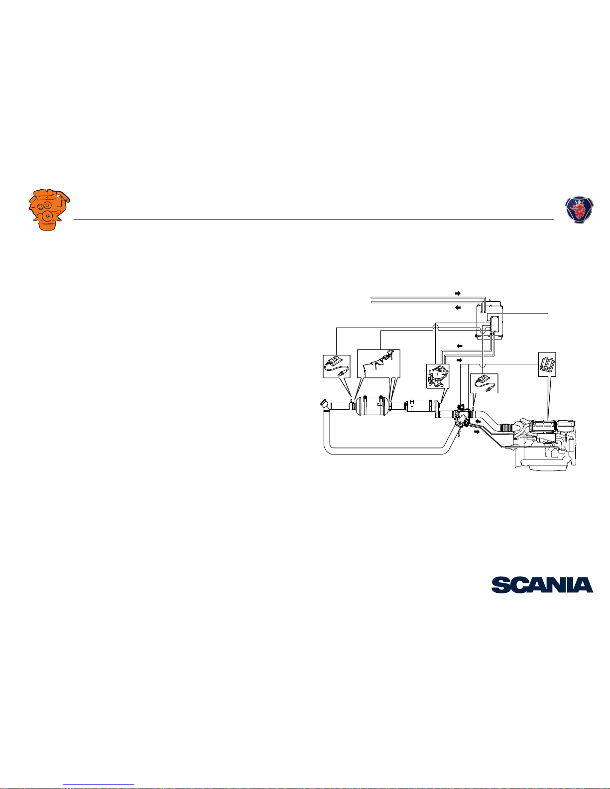
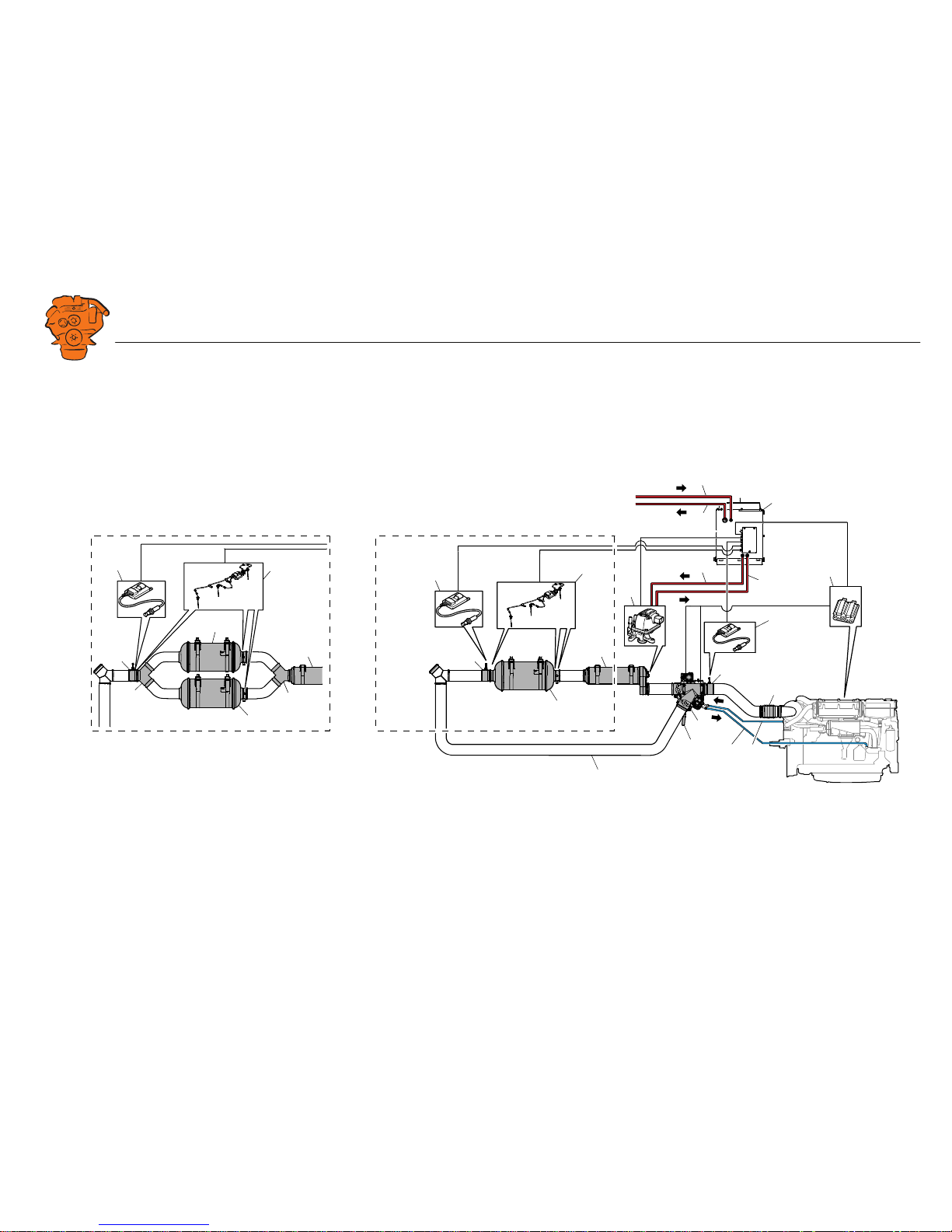
System overview
AB
368 025
1
2
4
3
5
6
7
8
10
9
11
12
13
14
1515
16
16
17
17
17
18
7
7
18
20
20
19
A: DI16.
B: DI13.

INSTALLATION
MANUAL
© Scania CV AB 2016, Sweden
System overview
02:07 Issue 1.0 en-GB 5
Component Standard Option Fitted by fitter
1. Pressure pipe for reductant from the main tank - - x
2. Return pipe for reductant to the main tank - - x
3. Reductant tank (buffer tank) x - x
4. Pressure pipe for reductant from the buffer tank - - x
5. Return pipe for reductant to buffer tank - - x
6. Engine control unit x- -
7. NOx sensor (x 2) x- x
8. Exhaust bellows -xx
9. Coolant line from the engine to the exhaust control valve actuator - - x
10. Coolant return --x
11. Pipe section with outlet for NOx sensor T131 x - x
12. Exhaust routing valve with 2 actuators x - x
13. Handle to bypass the SCR system x - -
14. Reductant doser x- -
15. Evaporator x- x
16. Exhaust temperature sensor (x 3) x - x
17. SCR catalytic converter with outlets for 2 exhaust gas temperature sensors x - x
18. Pipe section with outlet for NOx sensor T115 and 1 exhaust gas temperature sensor x - x
19. Bypass pipe --x
20. Branch pipe (DI16 only) x - x

INSTALLATION
MANUAL
© Scania CV AB 2016, Sweden
Exhaust pipe
02:07 Issue 1.0 en-GB 6
Exhaust pipe
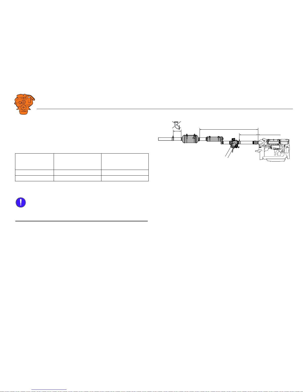
Pipe lengths
From To Max/min pipe length (mm)
A Turbocharger Pipe section for NOx sensor Max 1,500
B Turbocharger Evaporator intake Max 2,000
C Exhaust routing valve outlet Evaporator intake Max 500
D
1
1. DI16 only.
Evaporator outlet Branch pipe Min 300
E Evaporator outlet SCR catalytic converter inlet Max 1,500
F SCR catalytic converter outlet Pipe section for NOx sensor and exhaust temperature sensor Max 400
G Pipe section for NOx sensor and exhaust temperature sensor Exhaust outlet Min 500
12
A
B
C
E
F
DG G
E
F
368 800
1. DI16.
2. DI13.
INSTALLATION
MANUAL
© Scania CV AB 2016, Sweden
Exhaust pipe
02:07 Issue 1.0 en-GB 7
Exhaust pipe bends
The sum of the exhaust pipe bends between the turbocharger outlet and NOx sensor
upstream of the exhaust routing valve must not exceed 270°.
The sum of the exhaust pipe bends between the turbocharger outlet and SCR catalytic
converter inlet must not exceed 540°. Example:
The radius of the exhaust pipe bends must be at least 1.5 x pipe diameter, based on a
pipe diameter of 127 mm (5 inches).
IMPORTANT!
No exhaust pipe bends may be installed between the SCR catalytic converter outlet
and the NOx sensor downstream of the SCR catalytic converter.
Max. angle before
Number of 90° exhaust
pipe bends
Number of 45° exhaust
pipe bends
SCR catalytic converter
540° 4 off 4 off
540° 6 off 0 off
379 171
Max 540°
Max 270°
Max. number of exhaust pipe bends in the SCR system.
INSTALLATION
MANUAL
© Scania CV AB 2016, Sweden
Exhaust pipe
02:07 Issue 1.0 en-GB 8
Pipe material
The exhaust pipe between the evaporator and the SCR catalytic converter must be
made from stainless metal type 1.4301 or 1.4509, US grade 316L or equivalent. Scania also recommends that this material is used for other exhaust pipes downstream of
the SCR catalytic converter. Other instructions on exhaust system shape and fitting
are available in 02:04 Exhaust system.
Other requirements
IMPORTANT!
There should always be a flexible connection between the exhaust system and the engine which absorbs the movement of the engine and changes in length in the exhaust
system due to temperature changes. Also see 02:04 Exhaust system.
The brackets for exhaust routing valve, bypass pipe, evaporator and SCR catalytic
converter must be able to bear the weight of the component. The weight of the components must not load the exhaust bellows or turbocharger.
Tighten the V-clamps in the SCR system after the engine has warmed up to working
temperature for the first time. Carry out the retightening when the engine has cooled
down again. Tightening torque 20 Nm.
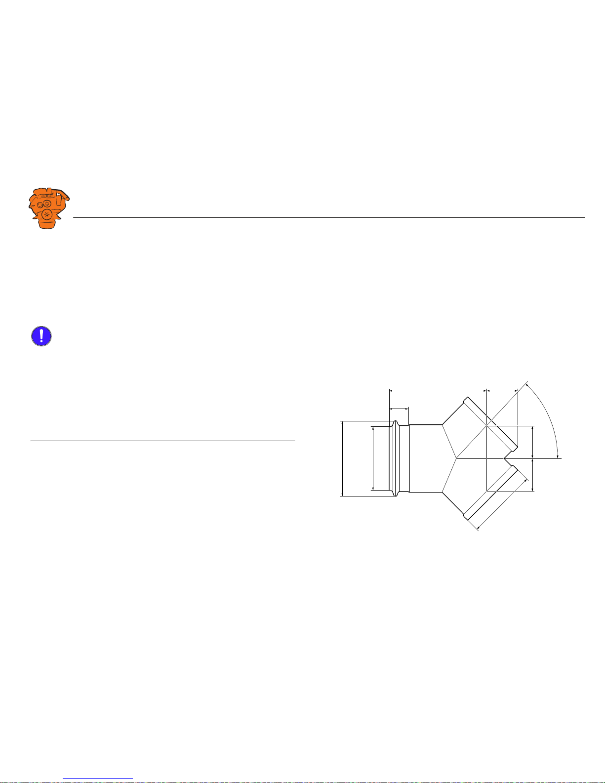
Branch pipe
The image shows the dimensions of the branch pipe used to connect the SCR catalytic converters to DI16.
366 031
2 x
2 x
45°
63,5
40
194
55
Ø122Ø144
Ø131 x 2
 Loading...