

Page 1
INSTALLATION
MANUAL
Marine engines
DI09, DI13, DI16
Engine
02:01 Issue 6.0 en-GB 1
©
Scania CV AB 2015, Sweden
Page 2

INSTALLATION
MANUAL
Engine suspension....................................................................................................3
Design requirements............................................................................................ 3
Flexible engine suspension.................................................................................. 4
Rigid engine suspension...................................................................................... 6
Suspension of reverse gear.................................................................................. 7
Permissible installation and operating angles ..................................................... 8
Flywheel housings............................................................................................... 9
Lifting the engine .............................................................................................. 10
Engine bed......................................................................................................... 10
Accessibility for maintenance and repairs ..........................................................11
Installation requirements ................................................................................... 11
Clearances ......................................................................................................... 13
Engine alignment...................................................................................................14
Flexible coupling............................................................................................... 15
Aligning engine and shafts................................................................................ 16
Power transmission ............................................................................................... 21
Flexible coupling............................................................................................... 21
Friction clutch ................................................................................................... 22
Transmission types ................................................................................................23
Mechanical transmissions ................................................................................. 23
Belt transmissions ............................................................................................. 23
Torsional oscillations ............................................................................................ 39
Data for torsional oscillation calculation.......................................................... 39
Torsional oscillation calculations from Scania................................................. 40
General tightening torques for screw joints ....................................................... 42
Specification of normal tightening torques....................................................... 42
Tightening torques ............................................................................................ 43
Power take-offs ......................................................................................................25
Front-mounted power take-offs......................................................................... 25
Side-mounted power take-offs .......................................................................... 27
Connection of sensors for external monitoring systems ....................................34
DI09 and DI13................................................................................................... 35
DI16................................................................................................................... 37
02:01 Issue 6.0 en-GB 2
©
Scania CV AB 2015, Sweden
Page 3
INSTALLATION
IMPORTANT!
MANUAL
Engine suspension
Design requirements
The type of engine suspension that is appropriate varies for different engine installations. In general, the following applies:
• The engine suspension should be designed for the forces it is exposed to, both
continuously and momentarily during operation. Such forces are reaction forces
from the transmitted torque and in some cases longitudinal acceleration, retardation and reaction forces in the engine.
• For engines with marine transmission, Scania recommends a 6-point suspension
or common rear suspension for pipes, transmission and engine.
• Both the engine suspension and the engine bed should be designed so that there
are no resonant oscillations within the engine speed range. They should also be
designed so that annoying vibrations from the engine are not transmitted to the
surroundings.
• The engine suspension and engine bed should be designed in a manner which allows access for maintenance and repair work.
• The engine bed location and the engine suspension must be designed so that the
permissible angles of inclination for the engine are not exceeded. See the table
Permissible installation and operating angles.
Engine suspension
If the angles of inclination are exceeded, lubrication system performance will deteriorate, which can cause damage to the engine or reduce its service life.
There are two standard engine suspension designs:
• flexible engine suspension
• rigid engine suspension.
02:01 Issue 6.0 en-GB 3
©
Scania CV AB 2015, Sweden
Page 4
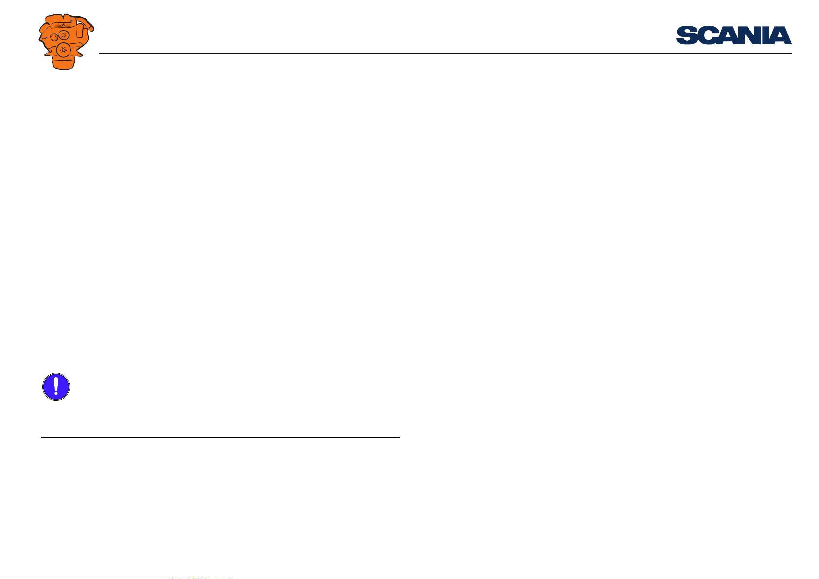
INSTALLATION
Examples of flexible engine suspension
MANUAL
Flexible engine suspension
Flexible engine suspension dampens vibrations more effectively than rigid engine
suspension. It prevents extreme movement between engine and engine bed during violent ship movement. Flexible engine suspension can also absorb some level of reaction force from the propeller. Flexible engine suspension does not require such
careful alignment of the engine as rigid engine suspension.
However, flexible engine suspension does not absorb longitudinal and lateral forces
in the engine to the same extent as rigid engine suspension.
Engine suspension
327 968
02:01 Issue 6.0 en-GB 4
©
Scania CV AB 2015, Sweden
Page 5
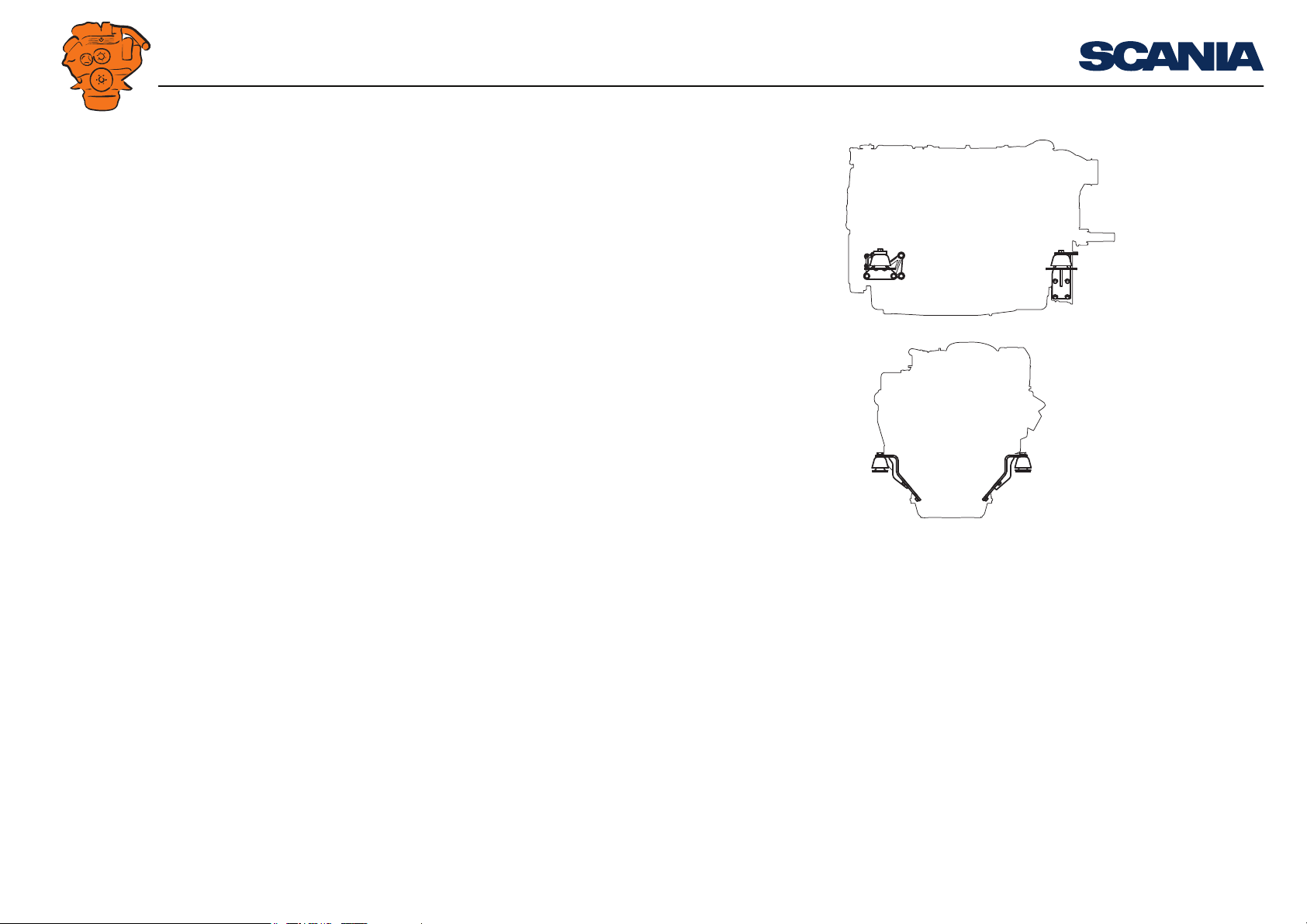
INSTALLATION
Tightening torque
Hardness marking
310 407
max 1°
310 406
0°
55
MANUAL
Insulators
Cushyfloat insulators with hardness 55 or 65 Shore can be ordered as option.
Engine suspension
160±10 Nm
310 404
310 405
55
55
alt. 65
310 408
0°
The engine bracket and frame or engine bed should be
parallel.
02:01 Issue 6.0 en-GB 5
Vertical centre lines should coincide laterally. Upper and lower parts of the insulators should be par-
allel longitudinally.
©
Scania CV AB 2015, Sweden
Page 6
INSTALLATION
Examples of rigid engine suspension
Example of rigid engine suspension for single-speed engines
MANUAL
Rigid engine suspension
A rigid engine suspension can absorb greater forces in all directions than flexible engine suspension. It requires highly accurate alignment of the engine in relation to the
driven unit. On the other hand, it requires no special flexibility in the hoses, pipes and
controls connected to the engine.
A rigid engine suspension can be used in engine installations where vibration causes
no significant problems and where other characteristics make it desirable.
Even with a rigid engine suspension, the transmission of vibration to the engine bed
can be kept low if the masses of the engine bed and connected parts are large in relation to the mass of the engine.
It is also possible to construct flexible engine suspension between the frame and the
engine bed to reduce the transmission of vibration to the engine bed.
Engine suspension
327 967
328 053
02:01 Issue 6.0 en-GB 6
©
Scania CV AB 2015, Sweden
Page 7
INSTALLATION
Example of suspension of a reverse gear
MANUAL
Suspension of reverse gear
Built-on reverse gear can either have separate brackets or suspension attachments
which are integrated with the engine.
Contact Scania or the supplier of the reverse gear about approved type of suspension
for reverse gear.
Engine suspension
327 753
02:01 Issue 6.0 en-GB 7
©
Scania CV AB 2015, Sweden
Page 8
INSTALLATION
MANUAL
Permissible installation and operating angles
Maximum permissible installation angle means maximum permissible installation
angle for an engine relative to the horizontal plane. The angle indicates the limit for
engine inclination during continuous operation.
Maximum operating angle means maximum permissible angle of inclination for an
engine in operation and with minimum oil level. The angle may only be used for
short periods. The maximum forward or rearward operating angles are not applicable
to their full extent if the engine is inclined laterally at the same time.
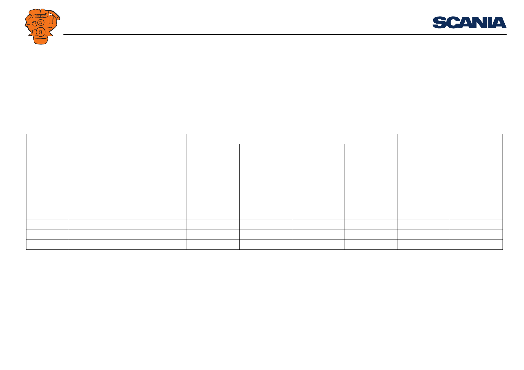
Engine type Type of oil sump Max. installation angle Max. operating angle Oil capacity (litres)
Inclination rearwards and forwards
DI09 Standard oil sump 12° 12° 30° 30° 32 38
DI09 Low oil sump 12° 12° 20° 30° 25 32
DI13 Standard oil sump with ladder frame 12° 12° 30° 30° 39 45
DI13 Standard oil sump without ladder frame 12° 12° 30° 30° 36 30
DI13 Low oil sump 12° 12° 25° 30° 28 34
DI13 Extra low oil sump 12° 12° 25° 30° 25 30
DI16 Standard oil sump 12° 10° 25° 30° 40 48
DI16 Low oil sump 12° 10° 25° 30° 29 37
Inclination laterally
Inclination rearwards and forwards
Inclination laterally
Min. Max.
Engine suspension
02:01 Issue 6.0 en-GB 8
©
Scania CV AB 2015, Sweden
Page 9

INSTALLATION
MANUAL
Flywheel housings
Silumin housings are supplied as standard on most marine engines, except on certain
16 litre engines. The maximum permissible bending torque for a silumin housing is
10,000 Nm. This presumes that there are no axial loads from, for example, the propeller shaft, abnormal G forces or vibration.
However, nodular iron flywheel housing can also be chosen. Nodular iron housings
can dampen vibrations at certain engine speeds but increase vibrations at other engine speeds. Nodular iron is stronger than silumin and can therefore tolerate greater
bending and torsional forces. Certain 16 litre engines have nodular iron casing as
standard.
The stronger nodular iron housings are recommended in installations where the flywheel housing is exposed to serious stress, e.g. with high reverse gear ratios and
when heavy components without support are attached to the rear of the engine (e.g.
hydraulic pump). Nodular iron housings are also recommended for generator sets
with high outputs.
The propeller installation without separate thrust bearing can be approved if the following requirements are met:
Engine suspension
• Max. pressure load from the propeller must not exceed 40,000 N.
• Reverse gear ratio must not exceed 2:1.
• The suspension must be on the front engine bracket and the common bracket for
the rear edge of the engine and the reverse gear.
• The displacement between the input and output shaft of the reverse gear must not
exceed 250 mm.
• Most of the propeller force must be taken up by the rear suspension.
• The support points of the brackets must be aligned with the propeller shaft as
much as possible.
02:01 Issue 6.0 en-GB 9
©
Scania CV AB 2015, Sweden
Page 10
INSTALLATION
Note:
WARNING!
MANUAL
The suspension must be dimensioned for the appropriate pressure load.
For the installation to be approved in a propeller installation with a reverse gear ratio
greater than 2:1, the pressure forces must be fully taken up in the reverse gear suspension.
Contact Scania if it is difficult to determine the size and type of load.
Lifting the engine
The engine lifting eyes are dimensioned for lifting the engine only, not the engine together with connected equipment or frame!
Engine suspension
Engine bed
The engine bed should be made as robust and rigid as possible. The attachment to the
hull should be as widely distributed as possible.
The engine bed should have welded support plates for engine and reverse gear. The
brackets should be as low as possible. Accessibility underneath the engine must be
good so that the oil sump can be removed for example.
There must be space for spacers with a thickness of 5-10 mm between the engine
brackets and the engine bed brackets for accurate alignment.
02:01 Issue 6.0 en-GB 10
©
Scania CV AB 2015, Sweden
Page 11

INSTALLATION
Note:
MANUAL
Accessibility for maintenance and repairs
Installation requirements
The installer is responsible for ensuring that accessibility is ensured for maintenance
and repairs.
There must be sufficient space at installation so that standard times for maintenance
and repairs can be attained.
The following requirements for accessibility must be met:
• Canopies and connected components must be designed so that the engine can be
removed and fitted without time being lost due to obstructive structures.
• In the case of static engine installations, there should be permanent securing
points for lifting devices above the unit.
• The fuel system must be easily accessible for maintenance and bleeding.
• It should be possible to read the graduations on the flywheel when adjusting
valves and unit injectors.
• It should be possible to remove and fit the cylinder head, rocker covers and pushrods while leaving the engine in place.
• It must be possible to remove the oil sump in order to renew cylinder liners or pistons with the engine in place.
• It should be easy to fill and drain oil. In addition, the oil dipstick must be easily
accessible.
• Centrifugal oil cleaners and oil filters must be easy to access for maintenance and
renewal.
• It should be easy to fill and drain coolant.
• Engine air filters must be located so that they are easy to access for the renewal
of filter elements.
Accessibility for maintenance and repairs
02:01 Issue 6.0 en-GB 11
©
Scania CV AB 2015, Sweden
Page 12

INSTALLATION
MANUAL
It must also be easy to carry out maintenance on the following components:
• Turbocharger
• Starter motor
• Generator
• Coolant pump
• Seawater pump and seawater filter
• Heat exchanger
• Sacrificial anodes
• Clutch
• Batteries
Accessibility for maintenance and repairs
02:01 Issue 6.0 en-GB 12
©
Scania CV AB 2015, Sweden
Page 13
INSTALLATION
MANUAL
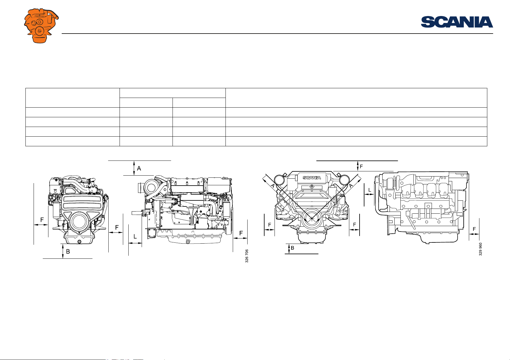
Clearances
The most important clearances are shown in the table and illustrations below. The
specified measurements apply to the largest standard equipment.
Measurement Clearance (mm) For maintenance or renewal of
DI09, DI13 DI16
A 150 900 Cylinder liner, cylinder head etc.
B 250 300 Oil sump
F 400 400 Various units
L 150 150 Seawater pump impeller
Accessibility for maintenance and repairs
Clearances for DI09 and DI13 Clearances for DI16
02:01 Issue 6.0 en-GB 13
©
Scania CV AB 2015, Sweden
Page 14

INSTALLATION
MANUAL
Engine alignment
The alignment of the engine in relation to the driven unit is very important in order
to prevent malfunctions.
Otherwise there is a risk of vibration and serious stress to the crankshaft, engine
brackets, drive shaft and coupling, causing damage which is costly to repair.
For propeller installations, a first alignment is made before the ship is launched.
Alignment must then be checked after the ship is launched and has been placed under
load. The ship should also be laden and equipped with filled tanks.
Since there can be some settling in the hull after the first hours of operation, further
checks on the alignment should be made after a period in service.
Alignment should be checked regularly on certain vibration-sensitive engine installations.
If flexible engine suspension is part of the system, this should be placed under load
before alignment. Otherwise, it will quickly settle by several millimeters.
Engine alignment
Poor alignment between engine and propeller shaft can cause damaging vibration in
the hull, damage to the reverse gear and accelerated wear of the shaft and propeller
bearings.
02:01 Issue 6.0 en-GB 14
©
Scania CV AB 2015, Sweden
Page 15

INSTALLATION
MANUAL
Flexible coupling
The alignment requirements are reduced if a flexible coupling is installed between
the engine and the driven unit. Refer to the data on the flexible coupling concerned
for permissible deviations.
Flexible coupling allows a certain angular displacement towards the output shaft. It
also has an effect of evening out irregularities in torque and therefore counteracts the
tendency towards torsional oscillation. The correct choice of rubber hardness reduces
the stress on the driven units.
Relatively large deviations are permissible with flexible couplings. However, alignment should be as accurate as possible to achieve low vibration and a long service
life on the coupling.
Engine alignment
02:01 Issue 6.0 en-GB 15
©
Scania CV AB 2015, Sweden
Page 16

INSTALLATION
2
1
344 283
Measuring the angular deviation
MANUAL
Aligning engine and shafts
Start from the driven shaft when aligning. First check that this is straight. Alignment
is made easier if the engine brackets are equipped with adjusting screws for vertical
and lateral adjustment. However, permanent setting should be made using shims.
Adjust the engine alignment vertically using shims between the engine bed and engine suspension and laterally by moving the engine sideways on the surface. Shafts
with flanges: Start by aligning roughly and secure the engine to its engine bed. Mate
the flanges (1) so that the guide edge of one flange enters the guide hole of the other
flange.
Calculation of angular deviation
1. Fit the stand for the dial gauge (2) to the driving flange.
2. Align the tip of the dial gauge with the axial surface of the other flange as far as
possible.
3. Zero the dial gauge at 12 o'clock.
4. Place one of the retaining screws through both flanges without tightening it.
5. Turn the shafts at the same time and read the dial gauge at intervals of 90° while
turning one revolution. Enter the values in the table. Make sure you use the right
signs.
6. Calculate the angular deviation between the shafts using the values.
Engine alignment
Location of measurement point
Measurement value
1
12 o'clock ±0 mm
3 o'clock ± mm
6 o'clock ± mm
9 o'clock ± mm
1. + means inwards and - means outwards
02:01 Issue 6.0 en-GB 16
©
Scania CV AB 2015, Sweden
Page 17

INSTALLATION
Note:
MANUAL
Calculating thickness of required shims
Make sure you use the right signs in the calculations.
t = thickness of required shims.
L = distance between engine suspensions.
D = diameter of the flange where the dial gauge is mounted.
6
o'clockx
t =
L
D
• If t is positive, shims should be added to the front or removed from the rear.
• If t is negative, shims should be added to the rear or removed from the front.
Engine alignment
02:01 Issue 6.0 en-GB 17
©
Scania CV AB 2015, Sweden
Page 18

INSTALLATION
Note:
344 284
MANUAL
Calculating lateral adjustment
Make sure you use the right signs in the calculations.
s = lateral displacement of engine suspension.
L = distance between engine suspensions.
D = diameter of the flange where the dial gauge is mounted.
(3 o'clock - 9
o'clock) x L
s =
D
• If s is positive, the front engine suspension must be moved to the right.
• If s is negative, the front engine suspension must be moved to the left.
Engine alignment
Checking parallelism of the flanges with a feeler gauge
Angular deviation between the shaft centrelines can also be checked using a 0.1 mm
feeler gauge. Do this by measuring the distance between the surfaces of the flanges
at the outer edges.
During measurement, the engine must be tightened onto the engine bed.
02:01 Issue 6.0 en-GB 18
©
Scania CV AB 2015, Sweden
Page 19

INSTALLATION
2
1
344 287
Measuring centring
MANUAL
Measuring parallel displacement
1. Move the tip of the dial gauge to the radial surface of the flange. Pull apart the
flanges (1) so that the guide edge is released as depicted in the figure to the right.
2. Zero the dial gauge (2) at 12 o'clock.
3. Lift or press down the driven shaft as far as the radial clearance will allow. Read
the dial gauge and enter the reading with the correct sign on the radial clearance
line.
If the driven shaft is very long, there must also be compensation for bending of
the shaft from its own weight. This can be obtained by lifting the end of the shaft
using a spring balance, which then shows the weight of the flange and half the
free part of the shaft. Deflection can then be calculated using this weight.
The same must also be done if the drive shaft is long or has some play.
4. Reset the dial gauge again. Place one of the retaining screws through both flanges
without tightening it.
5. Turn the shafts at the same time, read the dial gauge at intervals of 90° while turn-
ing one revolution and enter the values in the table. Make sure you use the right
signs.
6. Calculate the parallel displacement between the shafts using these values.
Engine alignment
Location of measure-
Measurement value
1
ment point
12 o'clock ±0 mm
3 o'clock ± mm
6 o'clock ± mm
9 o'clock ± mm
Radial clearance
1. + means inwards and - means outwards
2. + means lift and - means press
02:01 Issue 6.0 en-GB 19
2
±mm
©
Scania CV AB 2015, Sweden
Page 20

INSTALLATION
Note:
2
344 288
Measuring with free shaft ends
MANUAL
Calculating parallel displacement
Make sure you use the right signs.
Vertical
6 o'clock +
clearance
t =
2
Lateral
3 o'clock +
9 o'clock
t =
2
Shafts without flange
If both shaft ends are free during alignment, alignment can be checked using a dial
gauge (2) set up as depicted in the figure. Readings should be taken with the tip of
the dial gauge in two different places at least 200 mm apart axially. Turn the shafts
at the same time and read the results on the dial gauge.
Engine alignment
Permissible deviations
After taking measurements, a final check should be made. All screws, except those
for the flange joint, should be tightened to the torque specified by the manufacturer.
Upon measurement, deviation should not exceed 0.1 mm.
The requirements for the accuracy of the alignment can vary depending on the design
of the engine installation. If the requirements for accuracy are lower, the permissible
deviation may be greater than indicated above.
02:01 Issue 6.0 en-GB 20
©
Scania CV AB 2015, Sweden
Page 21

INSTALLATION
MANUAL
Power transmission
Engine torque is normally transmitted to the driven unit in one of the following ways:
• Through a flexible coupling which cannot be disengaged, e.g. engines for generator sets.
• Through a flexible coupling and via the reverse gear and reduction gear.
• Through a friction coupling, possibly also used together with a flexible coupling,
and via a reduction gear, torque converter or belt transmission.
Flexible coupling
Many engine installations require a flexible coupling between the engine and the
driven unit to dampen irregularities in the system.
Carry out a torsional oscillation calculation before selecting a flexible coupling.
When a flexible coupling is recommended based on the torsional oscillation calculation, it is important that the coupling installed and other transmission equipment follow the precise specification of the calculation.
Power transmission
For operation with generator set, there must be no play in the flexible coupling between the engine and generator.
02:01 Issue 6.0 en-GB 21
©
Scania CV AB 2015, Sweden
Page 22

INSTALLATION
Note:
MANUAL
Friction clutch
Marine engine installations use a friction clutch of the industrial clutch type, e.g. for
belt transmissions. The reason for this is that it has a great capacity and it can transfer
a large starting torque.
There are many different makes of industrial clutches on the market.
It is important that the industrial clutch is not subjected to loads that could cause
overloading of the clutch bearings.
For heavier operation, e.g. belt transmissions where large lateral forces arise, Scania
recommends using clutches which absorb lateral forces in the main bearings. This
type of clutch does not have a support bearing in the flywheel.
It is also important that a remote-controlled clutch has no remaining pressure on the
release bearing, neither when engaged nor disengaged, since the release bearing is
then subject to rapid wear. For this type of clutch operation, we recommend the use
of ball bearings as release bearings.
See the illustration in section Belt transmission in multi-engine installations on how
a belt transmission should be set up in a multi-engine installation.
Power transmission
The crankshaft should not be subjected to axial pressure from the clutch. This must
be checked after fitting.
02:01 Issue 6.0 en-GB 22
©
Scania CV AB 2015, Sweden
Page 23

INSTALLATION
Note:
MANUAL
Transmission types
Mechanical transmissions
Mechanical transmissions are the most common type on single engine installations.
These may be reverse gears or reduction gears.
If an engine is supplied without gear or gearbox, appropriate parts of the engine (flywheel, flywheel housings etc.) can still be adapted so that the gears and torque converters available on the market can be fitted.
For certain gears and torque converters, there are requirements to ensure that the axial run-out and radial run-out are not too great. Therefore check at installation to ensure that the supplier's requirements are met.
The crankshaft should not be subjected to axial pressure from the transmission. This
must be checked after fitting.
Transmission types
Belt transmissions
Belt transmissions are appropriate especially in multi-engine installations where two
or more engines drive a common output shaft. One of the advantages of a belt transmission is that it is easy to adapt to the appropriate gear ratio.
The belt transmission functions to some extent as a flexible coupling, runs silently
and has a long service life. Apart from checking belt tension and alignment, belt
transmissions do not require any special maintenance.
There are belt transmissions with different types of belts, such as single V-belts and
devices consisting of two or more V-belts coupled together.
02:01 Issue 6.0 en-GB 23
©
Scania CV AB 2015, Sweden
Page 24

INSTALLATION
IMPORTANT!
AB
328 056
Ø0.8
12 134 5
Example of engine in multi-engine installation with belt drive
A = Bearing shaft
B = Engine shaft
1. Steel bearing housing
2. Pulley with belts
3. Universal joint or flexible coupling
4. Flexible coupling
5. Industrial clutch
MANUAL
Which belt type to choose depends on several factors. More information and help in
dimensioning a belt transmission can be obtained from the belt manufacturer.
Large lateral forces may arise during belt operation. Accurate alignment and checking of the belt tension are therefore necessary. A different belt tension results in increased bearing load and displacement of the centre of the load. The lateral loading
can be reduced by e.g. changing the size of the pulley.
The manufacturer can provide information about permissible lateral forces and belt
tensioning for belt transmission in each case.
Belt transmission in multi-engine installations
In multi-engine installations with a belt transmission, the alignment of the engine and
bearings on the frame should be checked after the installation is complete.
In addition, you should also check that the pulley is properly secured to the shaft so
that it cannot wander after start-up.
Transmission types
Shafts A and B should be sufficiently parallel that their centrelines fall within a circle
with a diameter of 0.8 mm. See the illustration.
Check that the support bearings have sufficient lubricant as per the manufacturer's
instructions. There are both oil and grease lubricated bearings.
Always use paired belts or V-belts in multi-belt installations.
02:01 Issue 6.0 en-GB 24
©
Scania CV AB 2015, Sweden
Page 25

INSTALLATION
344 289
344 290
344 291
MANUAL
Power take-offs
The engines can be supplied with different types of power take-offs for driving units.
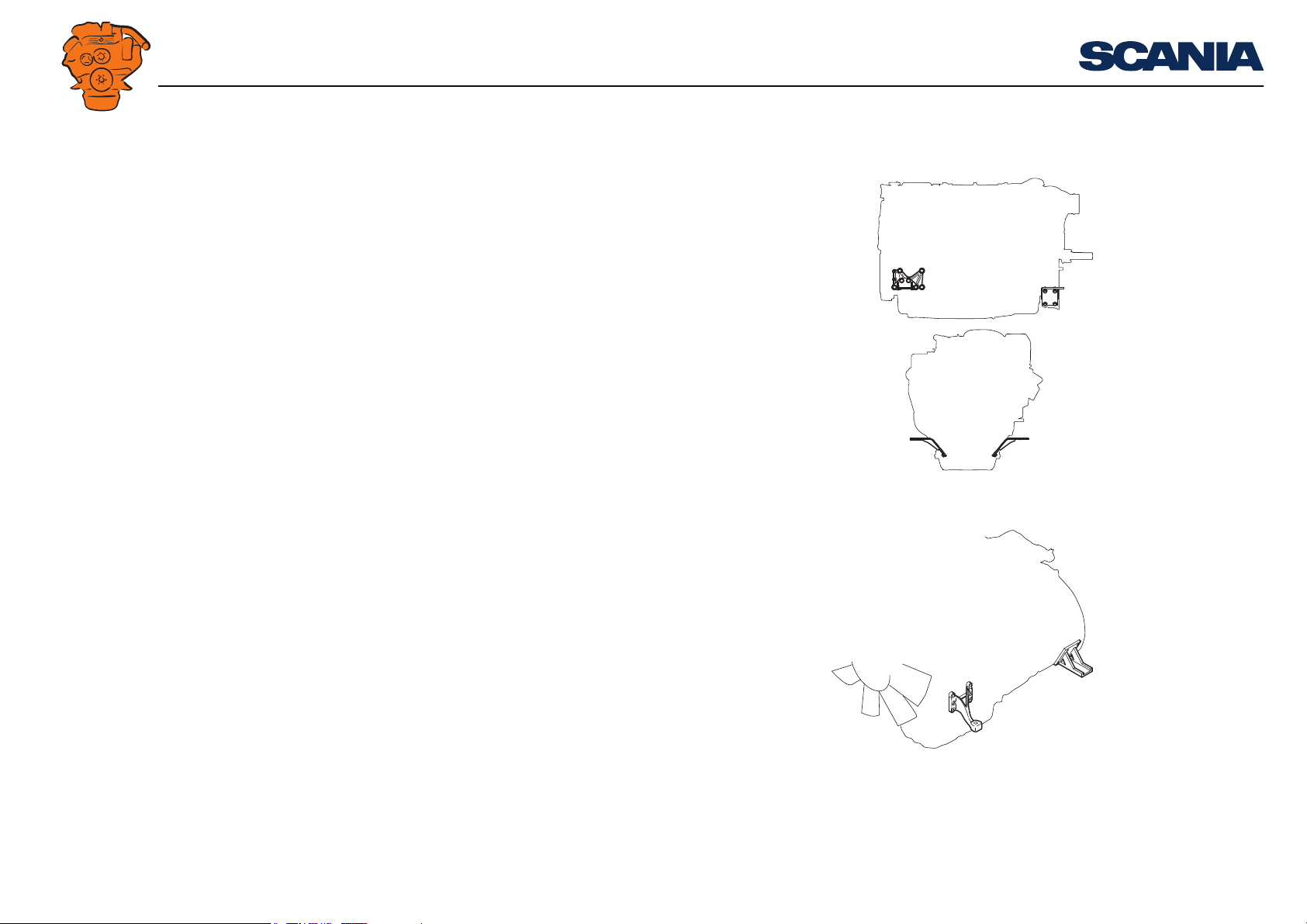
Front-mounted power take-offs
Example of shaft journal for direct connection of flexible coupling.
Power take-offs
Example of pulley on crankshaft.
Example of shaft journal and pulley.
02:01 Issue 6.0 en-GB 25
©
Scania CV AB 2015, Sweden
Page 26

INSTALLATION
344 292
MANUAL
Connection of flexible coupling to front end of crankshaft
The engine must be equipped with a shaft journal or flange driver which is mounted
on the crankshaft hub so that a flexible coupling can be connected at the front end of
the crankshaft.
The transmissible torque and power in the case of direct connection to the front end
of the crankshaft are limited primarily by engine type and the type of joint between
the crankshaft and hub.
Crankshaft pulley with two or more belt grooves
The belt grooves are designed for 12.5 mm (0.5") narrow V-belts, but A section Vbelts can also be used.
The transmission capacity of the V-belts determines the power available. Therefore
it is important that the belt manufacturer's instructions are adhered to when calculating transmissible power.
In order to avoid impermissible radial forces at the front end of the crankshaft when
there are many belts in the transmission, the driven units should be located so that the
forces balance out each other.
Power take-offs
Torque take-off and transmissible power from the front end of the crankshaft
Max. torque take-off is 1,200 Nm for DI13 and 800 Nm for DI09 and DI16. Transmissible power at different engine speeds is shown in the table below.
Engine speed (rpm) Max. transmissible power (kW)
DI13 DI09, DI16
1,500 188 125
1,800 226 151
1,900 239 160
2,000 251 168
2,100 264 176
02:01 Issue 6.0 en-GB 26
©
Scania CV AB 2015, Sweden
Page 27

INSTALLATION
IMPORTANT!
IMPORTANT!
MANUAL
Side-mounted power take-offs
The maximum torque that can be taken off from units connected to power take-offs
is indicated on the following pages.
The specified maximum torque assumes that the driven units have a relatively even
drive torque, e.g. centrifugal pumps, gear pumps or vane pumps.
In the case of units which have highly pulsed torque, e.g. piston pumps or piston
compressors with one or two cylinders, the permissible torque must be reduced. The
torque reduction is needed so that the average torque does not exceed the permissible
torque for continuous operation and the peak torque does not exceed the maximum
torque for intermittent operation.
When reducing permissible torque, consideration should be given to the torque reductions specified by the manufacturer of belts and flexible couplings.
Power take-offs
Also carry out an assessment as to whether connected units may have an effect on the
crankshaft and cause torsional oscillations in the shaft system.
Side-mounted power take-offs facing rearwards are not designed for driving without
a load. If these power take-offs are not loaded, they must be removed. Otherwise,
parts from the bearing housing may get into the engine and cause a breakdown.
Scania also recommends that SAE B power take-offs facing forwards are removed if
they are not to be loaded.
02:01 Issue 6.0 en-GB 27
©
Scania CV AB 2015, Sweden
Page 28

INSTALLATION
Note:
Note:
MANUAL
If several different side-mounted power take-offs are used, the maximum permitted
total torque take-off is 600 Nm.
The maximum permissible bending torque for all side-mounted power take-offs with
SAE B connection on all engine types is 30 Nm.
Overview of power take-off for DI09 and DI13
Power take-offs
Power take-offs Direction Connection Rotation Max. torque take-off
(Nm)
1 Backwards SAE B 300 1:1.19
2 Forward SAE B 300 1:1.19
3 Backwards SAE A 100 1:1.71
Transmissible power
Engine speed (rpm) Power take-off 1 (kW) Power take-off 2 (kW) Power take-off 3 (kW)
1,200 45 kW 45 kW 21 kW
1,500 56 kW 56 kW 27 kW
1,800 67 kW 67 kW 32 kW
1,900 71 kW 71 kW 34 kW
2,000 71 kW 71 kW 34 kW
2,100 71 kW 71 kW 34 kW
Gear ratio
02:01 Issue 6.0 en-GB 28
©
Scania CV AB 2015, Sweden
Page 29

INSTALLATION
MANUAL
Engine speed (rpm) Power take-off 1 (kW) Power take-off 2 (kW) Power take-off 3 (kW)
2,200 71 kW 71 kW 34 kW
Power take-offs
02:01 Issue 6.0 en-GB 29
©
Scania CV AB 2015, Sweden
Page 30

INSTALLATION
MANUAL
Overview of power take-off for DI16
Power take-offs
Power take-off Direction Connection Rotation Max. torque take-off
(Nm)
1 Backwards SAE B 300 1:1.19
Transmissible power
Engine speed (rpm) Power take-off 1 (kW)
1,200 45 kW
1,500 56 kW
1,800 67 kW
1,900 71 kW
2,000 71 kW
2,100 71 kW
2,200 71 kW
Gear ratio
02:01 Issue 6.0 en-GB 30
©
Scania CV AB 2015, Sweden
Page 31

INSTALLATION
Max 300 Nm
362 440
361 905
MANUAL
DI09 and DI13
Power take-off 1
The power take-off is located on the right of the rear of the engine.
Power take-offs
Power take-off 2
The power take-off is located low on the right of the rear of the engine, facing forward.
02:01 Issue 6.0 en-GB 31
©
Scania CV AB 2015, Sweden
Page 32

INSTALLATION
Note:
344 294
MANUAL
Power take-off 3
The power take-off is located on the left of the rear of the engine.
Power take-offs
Hydraulic pump
In the same location as power take-off 3, i.e. on the left of the rear of the engine, a
standard hydraulic pump can also be fitted here.
This hydraulic pump does not have an integrated pressure limiting valve. Such a
valve must therefore be installed in the system.
When the hydraulic pump is installed, the tank must be positioned higher than the hydraulic pump for the pump to have an even flow.
02:01 Issue 6.0 en-GB 32
©
Scania CV AB 2015, Sweden
Page 33

INSTALLATION
Note:
Max 300 Nm
362 441
MANUAL
DI16
Power take-off 1
The power take-off is located on the right of the rear of the engine.
Power take-offs
Hydraulic pump
A standard hydraulic pump can be fitted on the front of the engine. This hydraulic
pump does not have an integrated pressure limiting valve. Such a valve must therefore be installed in the system.
When the hydraulic pump is installed, the tank must be positioned higher than the hydraulic pump for the pump to have an even flow.
02:01 Issue 6.0 en-GB 33
©
Scania CV AB 2015, Sweden
Page 34

INSTALLATION
MANUAL
Connection of sensors for external monitoring systems
External monitoring systems for classed engines require in some cases that extra sensors are connected so that the following operating conditions can be monitored:
• coolant pressure
• coolant temperature
• oil pressure
• oil temperature
• fuel pressure
• engine speed
• charge air pressure (DI16 only)
• charge air temperature (DI16 only)
The following pages show suitable positions for installing such sensors.
Connection of sensors for external monitoring systems
Scania offer a classified electrical system for monitoring of coolant pressure, coolant
temperature, oil pressure, fuel pressure and engine speed.
How to connect the Scania monitoring system is described in the installation manual
03:03 – Instrumentation 2.0.
02:01 Issue 6.0 en-GB 34
©
Scania CV AB 2015, Sweden
Page 35

INSTALLATION
MANUAL
DI09 and DI13
Connection of sensors for external monitoring systems
1
2
337 695
328 055
1. Connecting the fuel pressure sensor
2. Connecting the oil temperature sensor, M30x2
02:01 Issue 6.0 en-GB 35
©
Scania CV AB 2015, Sweden
Connecting the oil pressure sensor, M16x1.5
Page 36

INSTALLATION
328 223
2
1
3
MANUAL
Connection of sensors for external monitoring systems
23 mm
23 mm
Connection of sensor for coolant temperature and coolant pressure Connection of engine speed sensor, Ø 18 mm,
2 x M6 screws
DI09 DI13
1. G1/2"
2. M14x1.5
1. M14x1.5
2. M18x1.5
328 054
3. M18x1.5
3. G1/2"
02:01 Issue 6.0 en-GB 36
©
Scania CV AB 2015, Sweden
Page 37

DI16
331 770
23
INSTALLATION
MANUAL
Connection of sensors for external monitoring systems
1. Connection of oil pressure sensor. The three-
Connection of engine speed sensor, Ø 18 mm, M6 screw
way union must be renewed for a four-way
union, which can be ordered as extra equipment
2. Connection of oil temperature sensor,
M24x2
02:01 Issue 6.0 en-GB 37
©
Scania CV AB 2015, Sweden
Page 38

INSTALLATION
331 772
1919
MANUAL
Connection of sensors for external monitoring systems
1. Connection of sensor for fuel pressure, M10x1
2. Connecting the sensor for coolant pressure,
M12x1.5
Connection of sensor for charge air pressure and
charge air temperature, Ø 16 mm, 2 x M6 screws
Connection of sensor for coolant temperature,
G1/2". If necessary, an adapter can be ordered
as extra equipment
02:01 Issue 6.0 en-GB 38
©
Scania CV AB 2015, Sweden
Page 39

INSTALLATION
IMPORTANT!
MANUAL
Torsional oscillations
Torsional oscillation arises in any shaft system which includes a combustion engine.
Depending on the combination of the design of the shaft system and the operating
speed, these oscillations may attain high amplitudes and therefore place great strain
on the equipment. This may even lead to total breakdown in a part of the shaft system. This process may be very rapid.
A torsional oscillation calculation must be carried out for each unique engine installation. The customer or installer is responsible for performing this calculation.
An unsuitably assembled installation may mean that it is necessary to limit the operating speed range or refrain from using a front-mounted power take-off.
If a torsional oscillation calculation is made at the planning stage, it is usually possible to easily adjust the shaft system to provide the safest engine installation.
Torsional oscillations
Data for torsional oscillation calculation
Form for torsional oscillation calculation is available on SAIL.
Contact your nearest Scania distributor if you require help downloading the form or
with the torsional oscillation calculation.
The following information is required for the calculation:
1. Engine type designation and classification society.
2. Operating speed and power.
02:01 Issue 6.0 en-GB 39
©
Scania CV AB 2015, Sweden
Page 40

INSTALLATION
MANUAL
3. The equipment fitted to the front and rear parts of the engine. State Scania part
number.
4. Gear ratios.
5. Moment of inertia (j) or rotating mass (GD2) for component couplings, flanges,
gears, shafts, propellers, generators and similar which rotate with the engine.
6. For couplings which can be disengaged, flexible couplings and similar the values
for the component parts are required. If the values are not available, a drawing of
the part is required showing diameters, widths and thicknesses of the component
parts.
7. Dynamic rigidities of flexible couplings, shafts and belt transmissions. However,
for shafts the material, length, outside and inside diameters, press-in lengths,
shrink-on lengths and similar can be stated. For belt transmissions, we require
shaft spacing, pulley diameters, belt type, number of belts and dynamic rigidities.
8. In the case of generator sets, a drawing of the generator shaft must be included
with the calculation if it is to be approved by a classification society.
Torsional oscillations
Torsional oscillation calculations from Scania
Scania's torsional oscillation calculations are made with direct frequency response
for all configurations up to 350 Hz in a linear system for the engine speeds in question. The calculation is based on technical data provided to Scania by the customer
or manufacturer for parts forming part of the elastic mass system which are not manufactured by Scania.
An approved calculation forms a guarantee against damage caused by torsional oscillations for all rotating parts from Scania that are included in the engine installation
under Scania's general warranty commitments. The approval should not be regarded
as a general system warranty in any other respect.
Scania only takes responsibility for parts in Scania's product range and not for any
other parts. Scania can, however, give a warning if the calculation shows that nonScania parts are subjected to high torsional amplitudes.
02:01 Issue 6.0 en-GB 40
©
Scania CV AB 2015, Sweden
Page 41

INSTALLATION
MANUAL
Together with the different subsuppliers, the supplier of the complete engine installation to the customer should confirm the torsional capacity and provide approval for
each component, based on the torsional oscillation calculation.
ISO 3046/V applies where appropriate.
The torsional oscillation calculation does not allow Scania to provide any statement
or guarantee as regards hunting.
Torsional oscillation calculations may also be performed by companies other than
Scania. The data required for performing these calculations can be obtained from
SAIL.
Torsional oscillations
02:01 Issue 6.0 en-GB 41
©
Scania CV AB 2015, Sweden
Page 42

INSTALLATION
MANUAL
General tightening torques for screw joints
Specification of normal tightening torques
The specifications in the tables on the following pages show the normal tightening
torques for screws and nuts.
The following conditions apply:
• A tolerance of ±15% applies to all values unless otherwise specified.
• All contact surfaces are to be clean and free of paint and the like.
• Screws and nuts are normally not lubricated regardless of surface treatment.
Union assemblies
The specified values apply with a tolerance of ±5%. The values apply to tightening
with a counterhold.
Thread inserts
The specified tightening torques also apply to screw joints with a thread insert (HeliCoil). Thread inserts often provide greater strength compared to a directly screwed
thread. This generates a stronger screw joint in aluminium or the like. For this reason,
thread inserts are used in certain joints in Scania's production.
General tightening torques for screw joints
02:01 Issue 6.0 en-GB 42
©
Scania CV AB 2015, Sweden
Page 43

INSTALLATION
321 514
MANUAL
Tightening torques
Hexagon screws, hexagon socket screws, Torx screws, hexagon nuts
Metric thread, coarse pitch
Thread Strength class 8.8/8
Tightening torque (Nm)
M4 2.9
M5 6
M6 9.5
M8 24
M10 47
M12 84
M14 135
M16 210
M18 290
M20 420
M22 580
M24 730
General tightening torques for screw joints
02:01 Issue 6.0 en-GB 43
©
Scania CV AB 2015, Sweden
Page 44

INSTALLATION
MANUAL
Flange screws with hexagonal head and hexagonal flange nuts
Metric thread, coarse pitch
Thread Strength class 8.8/8
Tightening torque (Nm)
M5 6.7
M6 10.2
M8 26
M10 50
M12 92
M14 149
M16 184
Thread forming Torx screws and hexagon screws with captive washer
General tightening torques for screw joints
321 515
Modified metric thread, coarse pitch
Thread Class 8 Class 10
Tightening torque (Nm)
M4 2.9 -
M6 9.4 11
M8 24 26
M10 47 49
321 504
M12 80 85
02:01 Issue 6.0 en-GB 44
©
Scania CV AB 2015, Sweden
Page 45

INSTALLATION
321 507
MANUAL
Stud end in threaded hole, strength class 8.8/8
Metric thread, coarse pitch
Tightening the stud end in the threaded hole must be done so that the stud does not
come loose when undoing the nut. To tighten the stud in the threaded hole the torque
must just overcome the friction in the thread and generate a preload. The torque for
locking is 50% of the normal torque for hexagon screws, hexagon socket screws,
Torx screws, hexagon nuts.
Union nuts for ferrule
Thread Tightening torque (in Nm, tolerance +/-15%)
For pipe diameter
M10x1 5 15 10 -
M12x1.5 6 20 10 -
M14x1.5 8 30 20 -
M16x1.5 10 40 25 15
M18x1.5 12 50 30 20
M20x1.5 12 55 35 -
M24x1.5 16 60 50 40
M30x2 22 120 - -
Steel pipe with
greased steel
nut
Plastic pipe with steel ferrule and brass or steel nut
General tightening torques for screw joints
321 506
Plastic pipe with brass ferrule and nut with rubber
seal
323 456
02:01 Issue 6.0 en-GB 45
©
Scania CV AB 2015, Sweden
Page 46

INSTALLATION
MANUAL
Special torques for engine suspension
Front engine suspension
Type of screw Tightening torque
25 mm clamping length, M16, 10.9 130 Nm, 90°
50 mm clamping length, M16, 10.9 130 Nm, 135°
Rear engine suspension?
Type of screw Tightening torque
M14, 8.8 149 Nm
General tightening torques for screw joints
02:01 Issue 6.0 en-GB 46
©
Scania CV AB 2015, Sweden
 Loading...