

Scania DI16, DI13, DI09 Service Manual
INSTALLATION
MANUAL
©
Scania CV AB 2016, Sweden
02:03 Issue 5.0 en-GB 1
Fuel system
Marine engines
DI09, DI13, DI16
333 381
INSTALLATION
MANUAL
©
Scania CV AB 2016, Sweden
02:03 Issue 5.0 en-GB 2
Fuel tank...................................................................................................................3
Position................................................................................................................ 3
Fuel tank design .................................................................................................. 4
Main tank and buffer tank ................................................................................... 4
Fuel pipes..................................................................................................................5
Minimum inside diameter of fuel lines ............................................................... 5
Fuel filter ..................................................................................................................6
PDE and XPI engines.......................................................................................... 6
PDE engines ........................................................................................................ 8
XPI engines ......................................................................................................... 9
Fuel cooler ..............................................................................................................10
Feed pump flow rates ............................................................................................11
PDE engines ...................................................................................................... 11
XPI engines ....................................................................................................... 11
Flow and pressure .................................................................................................12
PDE engines ...................................................................................................... 12
XPI engines ....................................................................................................... 12
Risk of fire..............................................................................................................13
Fuel grade and power for PDE engines...............................................................14
Important data.......................................................................................................16
INSTALLATION
MANUAL
©
Scania CV AB 2016, Sweden
Fuel tank
02:03 Issue 5.0 en-GB 3
Fuel tank
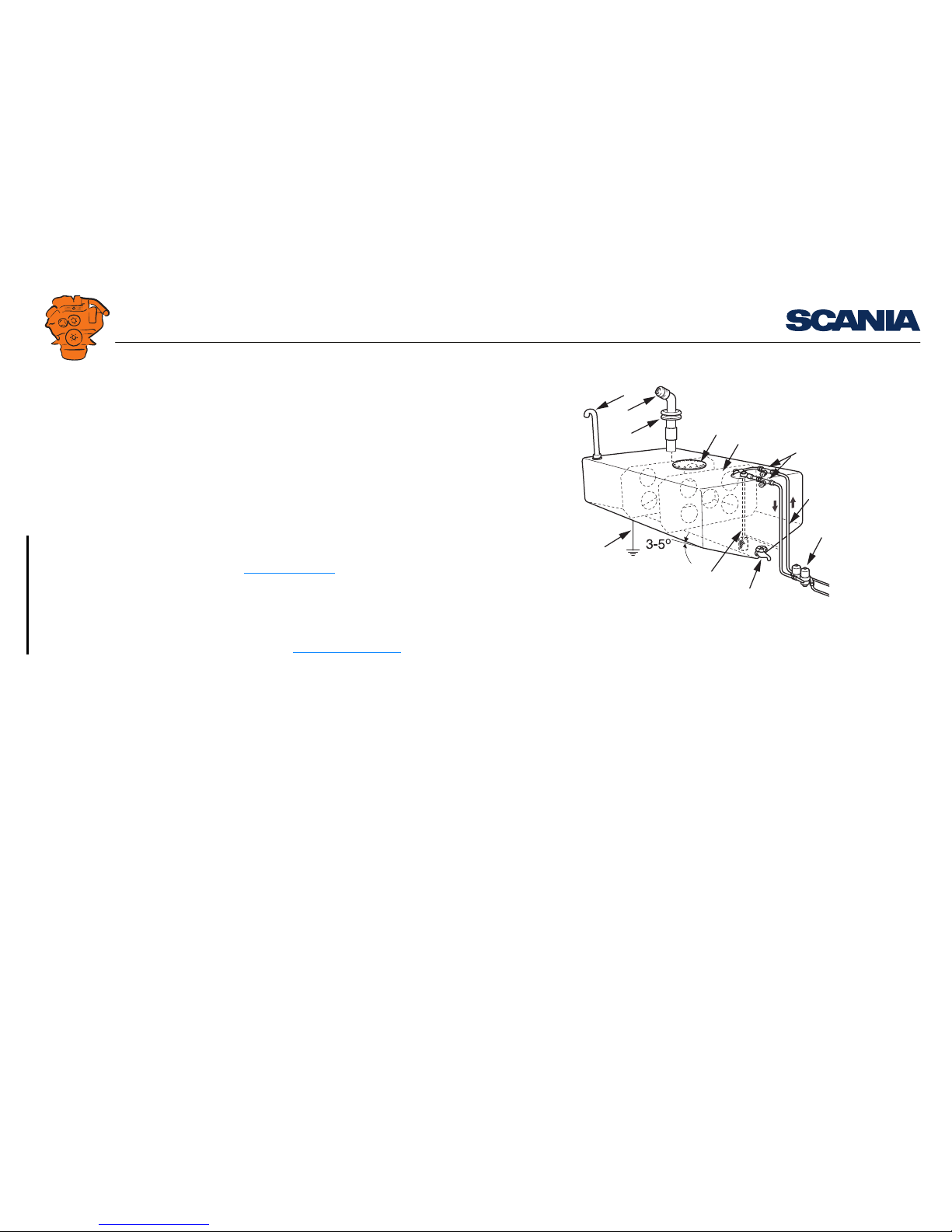
The illustration shows an example of a marine fuel tank installation.
Position
If the fuel tank is placed higher than the engine feed pump, a shut-off cock should be
installed in the fuel line to the feed pump. During downtime, this cock should be
closed. Maximum permitted fuel level in the fuel tank is 3.5 m in relation to the feed
pump.
The fuel tank must not be positioned so low that the vacuum in feed pump suction
pipe is greater than 0.3 bar. The risk of air leaks in the suction pipe increases with
increased vacuum. See also the section Flow and pressure
.
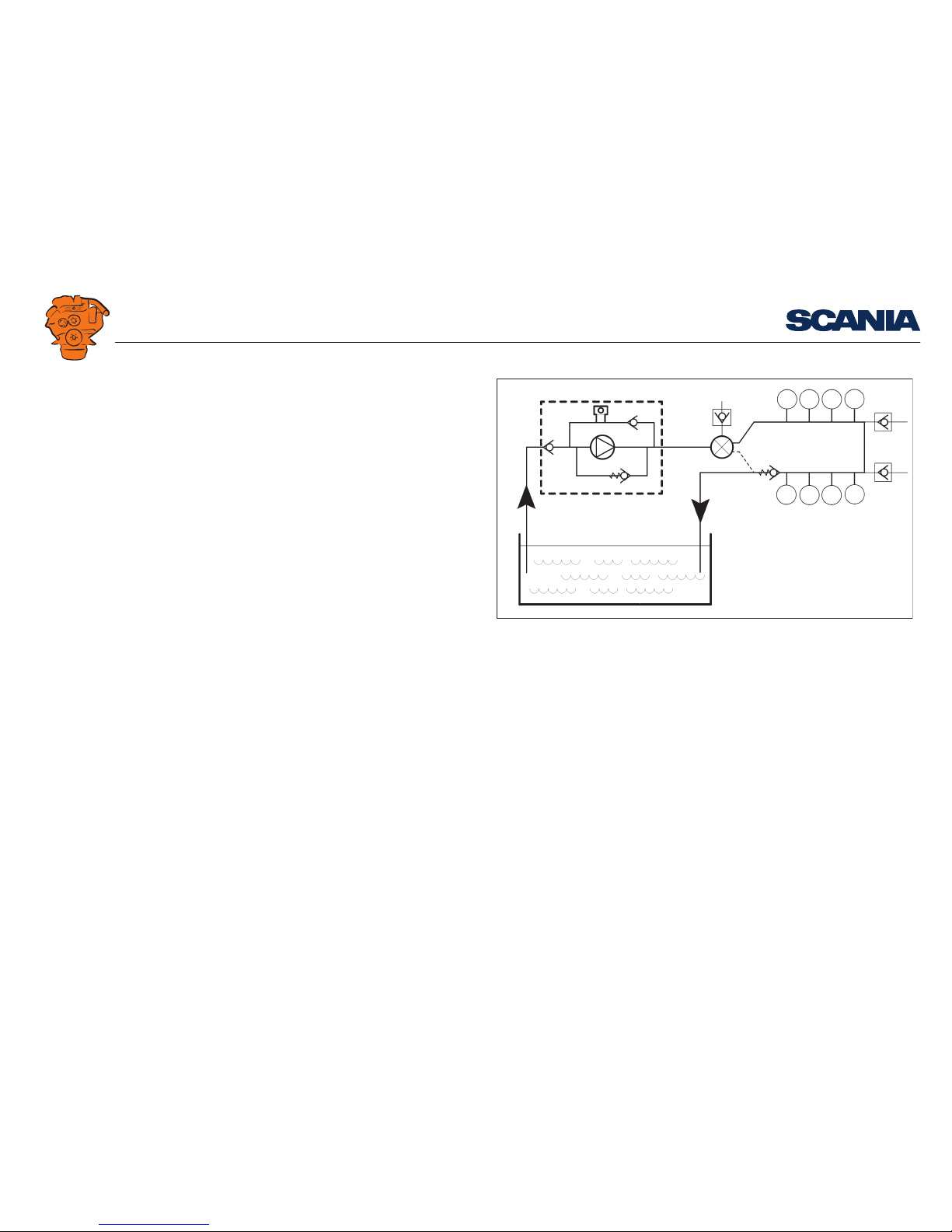
If the fuel tank is mounted so low that the maximum permissible vacuum is exceeded,
or if a large fuel tank is required which cannot be mounted close to the engine, a buffer tank must be installed at a suitable distance and height. A feed pump must be fitted
directly downstream of the tank. The flow for the auxiliary feed pump must be minimum 15% higher than the flows specified in the Feed pump flow rates
section.
If a reliable and quick starting response is required, the buffer tank should be positioned adjacent to the engine with the lowest fuel level at the same level as the feed
pump. If the fuel tank(s) are built in, the space should be well ventilated. The fuel
tank should normally be drained once a year, but this may vary depending on the
quality of the fuel.
4
5
6
7
8
9
10
11
1
2
3
338 166
Example of a fuel tank installation.
1. Bleed pipe.
2. Fuel filler pipe with filler cap.
3. Lead-through sleeve of fuel-resistant rubber.
4. Inspection hatch.
5. Baffle plate.
6. Fuel cocks.
7. Prefilter.
8. Drain tap for sludge and water.
9. Suction pipe with strainer.
10. Return pipe. Note: For XPI engines, it should enter below the lowest fuel level.
11. Ground connection.

INSTALLATION
MANUAL
©
Scania CV AB 2016, Sweden
Fuel tank
02:03 Issue 5.0 en-GB 4
Fuel tank design
The material for the fuel tank should be corrosion-resistant, such as stainless steel or
aluminium.
Note:
Some other materials, such as copper or hot dip galvanised sheet steel, are unsuitable
for use with diesel fuel.
The fuel tanks must be fully welded, and should have internal baffle plates to prevent
the fuel being thrown about in heavy seas. Both fuel filling components and the fuel
tank must be grounded to prevent sparking from static electricity. The fuel tank must
have the following devices:
• A drain tap for emptying sludge and water that has sunk to the bottom.
• A ventilation or bleed line from the upper part of the fuel tank to the outside of
the hull. It should be designed so that water cannot enter and so that fuel cannot
run out when the ship is leaning heavily.
• Protection or filter to prevent contaminants entering during filling.
• There must always be a fuel cock in the suction line and in the return line if its
outlet in the tank is higher than the outlet from the engine. The return line should
be routed to the upper part of the fuel tank.
• Main tanks must be fitted with inspection hatches so that they can be inspected
and cleaned inside.
New fuel tanks must be thoroughly cleaned and rinsed internally using clean fuel.
They must also be pressure tested to 0.3 bar.
Fuel tanks manufactured from materials which are not resistant to corrosion must be
treated externally with corrosion protection. The fuel tanks must not be painted internally nor be zinc-coated or galvanised.
It is important that the fuel tanks are positioned in as cool a location as possible since
the return fuel is hot and therefore raises the temperature of the fuel in the fuel tank.
Power correction due to the fuel temperature increase for PDE engines is displayed
in the tables in the Fuel grade and power for PDE engines
section.
Main tank and buffer tank
If the engine installation has a buffer tank and main tank, these should be designed
as follows:
• The main tank must have a sloped bottom or be on a slight incline (about 3-5°)
and have a tap at the lowest part for draining condensation.
• The pipe fittings must be connected or routed to approximately 50 mm from the
bottom and supplied with a bottom strainer. This applies to both the buffer tank
and the main tank.
• The lines to the buffer tank should be as short as possible and should be mounted
in such a way that they cannot be exposed to mechanical damage.
• Transfer of fuel from the main tank to the buffer tank should be achieved using
an electric pump connected so that it only pumps when the engine is running. This
is to prevent the risk of serious leakage when the engine is not running. The electric pump must have an excess capacity of 30-40% in relation to the engine fuel
consumption. This is to ensure that the quantity of return fuel is sufficient for lubrication and cooling.
• There must be a return pipe from the buffer tank to the main tank so that any surplus fuel runs back to the main tank.
• For PDE engines, the return pipe from the engine must be routed to the upper part
of the buffer tank.
• For XPI engines, the return pipe should enter below the lowest fuel level in the
main tank.
• The buffer tank must also be fitted with a drain tap for condensation.
See instructions in the Fuel tank design
section for further details.
INSTALLATION
MANUAL
©
Scania CV AB 2016, Sweden
Fuel pipes
02:03 Issue 5.0 en-GB 5
Fuel pipes
The fuel lines should be routed so that the fuel cannot be heated by radiated heat from
the engine.
The dependency of engine power on fuel temperature can be read in the tables in the
Fuel grade and power for PDE engines
section. Maximum permitted fuel temperature
in the inlet pipe is 60°C.
The return line must be routed to the fuel tank or to the buffer tank (if fitted).
Note:
The return line must not be connected to the suction line.
For PDE engines, the return line is normally connected to the upper part of the tank.
The return line should normally enter above the maximum fuel level. For PDE engines, the return pipe and suction pipe must have the same diameter.
Note:
For XPI engines, the fuel return line should enter below the lowest fuel level in the
fuel tank.
The suction line in the fuel tank should be placed at least 50 mm from the bottom of
the fuel tank. This distance also applies to the suction strainer.
In multi-engine installations, the fuel system should be divided into at least two independent systems so that a fault in one of the fuel lines does not cause all engines
to stop.
The fuel lines should not be made of copper as there is a risk of oxidation due to condensation. The sulphur content in the fuel can also have a negative effect on the copper.
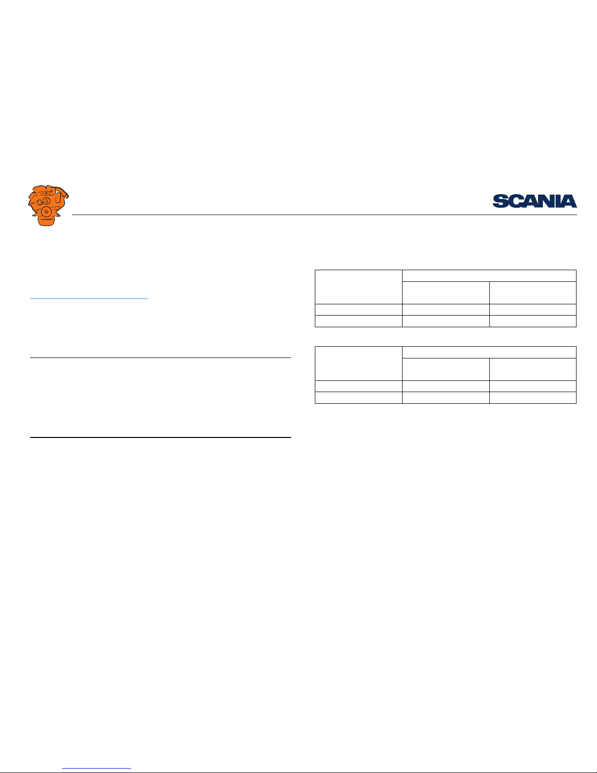
Minimum inside diameter of fuel lines
PDE engines
Type of fuel pipe Fuel pipe length
Shorter than 3 m, Longer than 3 m,
min. inner diam. (mm) min. inner diam. (mm)
Suction pipe 10 12
Return pipe 10 12
XPI engines
Type of fuel pipe Fuel pipe length
Shorter than 3 m, Longer than 3 m,
min. inner diam. (mm) min. inner diam. (mm)
Suction pipe 14 16
Return pipe 10 12
 Loading...