

Page 1
03:03 Issue 5.0 en-GB
© Scania CV AB 2016, Sweden
Installation manual
Instrumentation 2.0
Marine engines
DI09, DI13, DI16
344 457
Page 2

INSTALLATION
MANUAL
© Scania CV AB 2016, Sweden
03:03 Issue 5.0 en-GB 2
System overview ......................................................................................................3
List of abbreviations............................................................................................ 3
System overview ................................................................................................. 3
Positioning of the displays .................................................................................. 5
Connection ...............................................................................................................7
Electrical cables................................................................................................... 7
Junction box, connection..................................................................................... 8
Junction box, components................................................................................. 11
Main display (DCU), junction blocks ............................................................... 12
Auxiliary display (RP), junction blocks............................................................ 19
Safety module (SDU), connection .................................................................... 22
Gateway – overview.......................................................................................... 22
Position of the monitors on the engine.............................................................. 23
Connecting emergency stop .............................................................................. 25
Engine shutdown override in systems with safety device unit (SDU).............. 26
Using the main display ..........................................................................................27
First start............................................................................................................ 27
Navigation ......................................................................................................... 30
Administration in the main display ................................................................... 33
Configuring and upgrading software with USB memory stick.........................37
Configuring the main display with a USB memory stick ................................. 38
Upgrading the main display or auxiliary display software ............................... 39
Copying one configuration file in the main display.......................................... 39
Configuring the main display via a web browser............................................... 40
Connecting a computer to the main display...................................................... 40
General information about the IP address......................................................... 42
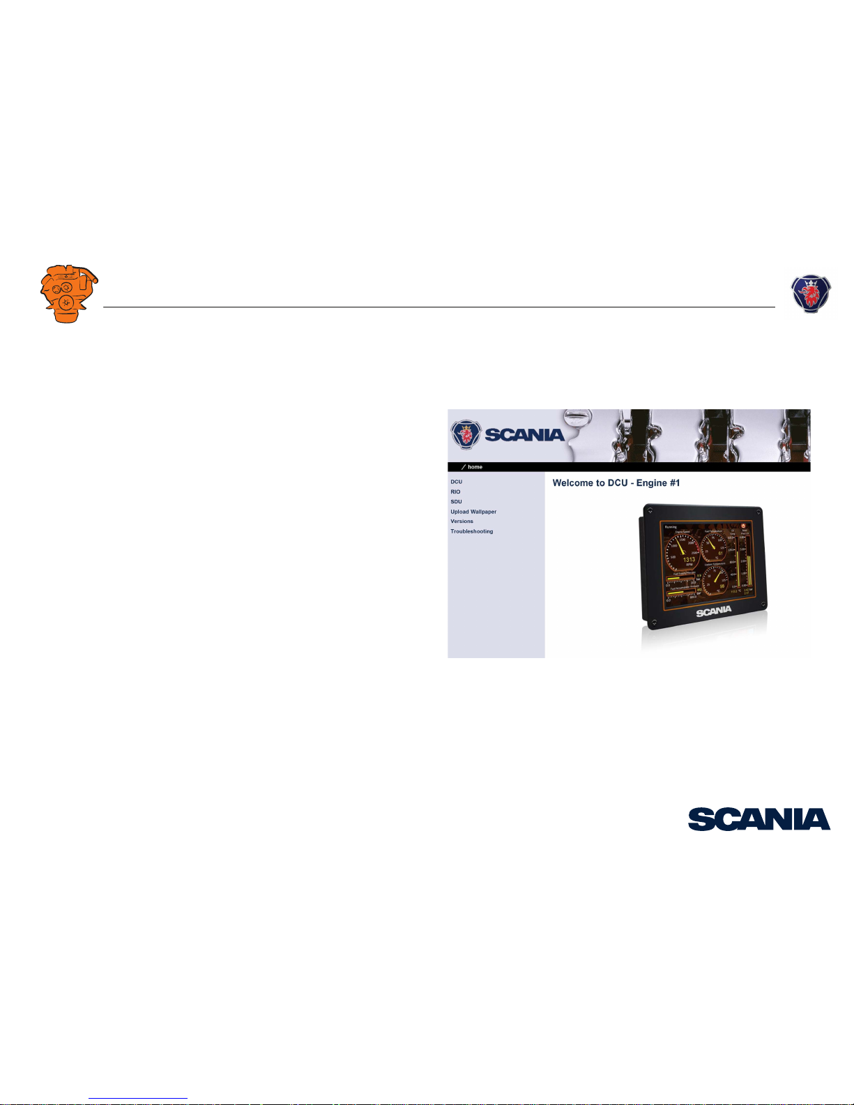
Homepage.......................................................................................................... 43
Logging in to the main display.......................................................................... 44
Important system settings: dcu / Miscellaneous / System Type........................ 44
Password: dcu > Password................................................................................ 45
File management: dcu > File ............................................................................ 46
Configuring input signals: dcu > I/O Configuration > Config Inputs .............. 47
Configure output signals: dcu > I/O Configuration / Config Outputs.............. 63
Designing instrument pages: dcu > Interface Design ....................................... 67
Set the sequences for starting, stopping and for lubrication: dcu > Start/Stop/Pre-
lube ................................................................................................................... 69
Settings for the user interface: dcu > User Interface ........................................ 72
Changing the engine designation: dcu > Engine Model................................... 73
Setting the maintenance interval: dcu > Service Interval ................................. 74
Network settings: dcu > Communication ......................................................... 75
Other functions: dcu > Miscellaneous .............................................................. 77
SDU .................................................................................................................. 82
Auxiliary display ................................................................................................... 83
First start ........................................................................................................... 83
Administration in the auxiliary display ............................................................ 85
Examples of connection of sensors and monitors .............................................. 92
Connection of 4-20 mA, e.g. oil pressure sensor for the reverse gear.............. 92
Connection of PT100, e.g. coolant temperature sensor.................................... 94
Connection of switch input, e.g. low engine oil pressure monitor ................... 96
Page 3
INSTALLATION
MANUAL
© Scania CV AB 2016, Sweden
System overview
03:03 Issue 5.0 en-GB 3
System overview
List of abbreviations
The abbreviations in the list below are used in this manual. DCU, RP och SDU appear in the display interface and in the configuration interface.
System overview
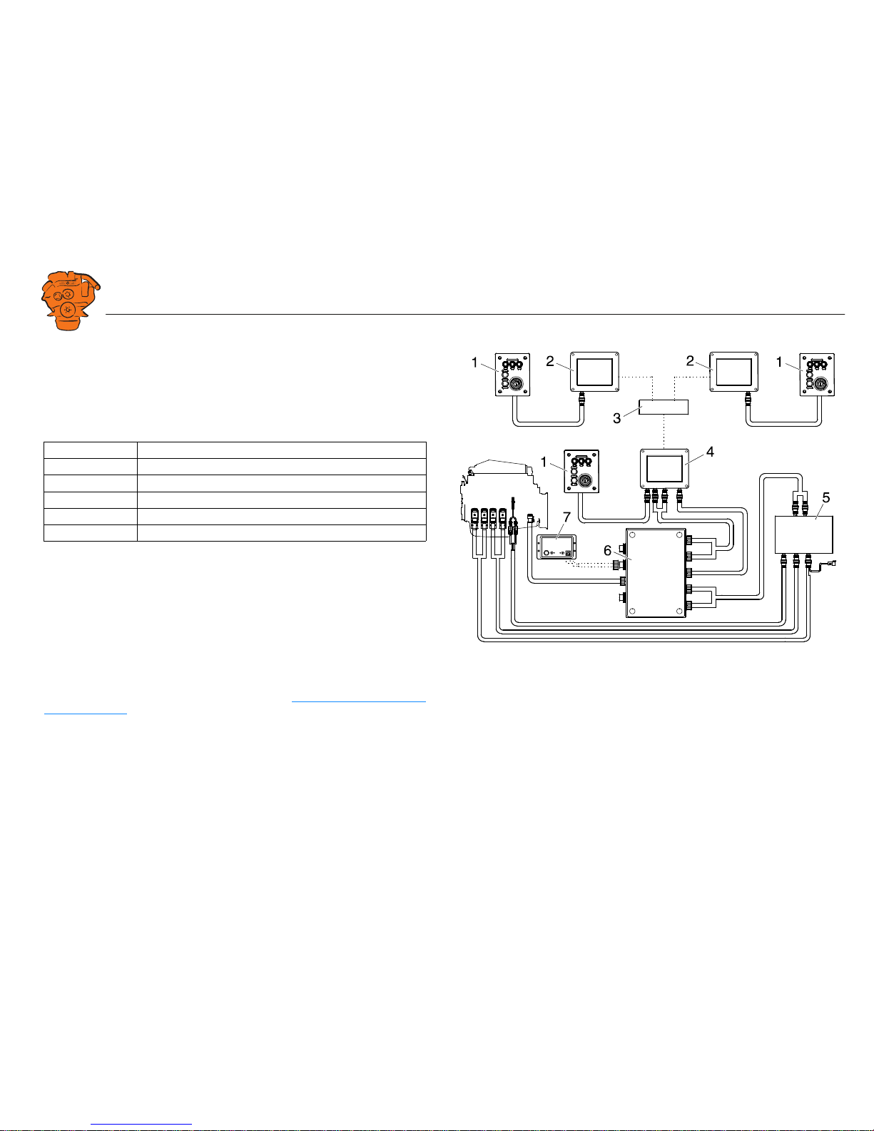
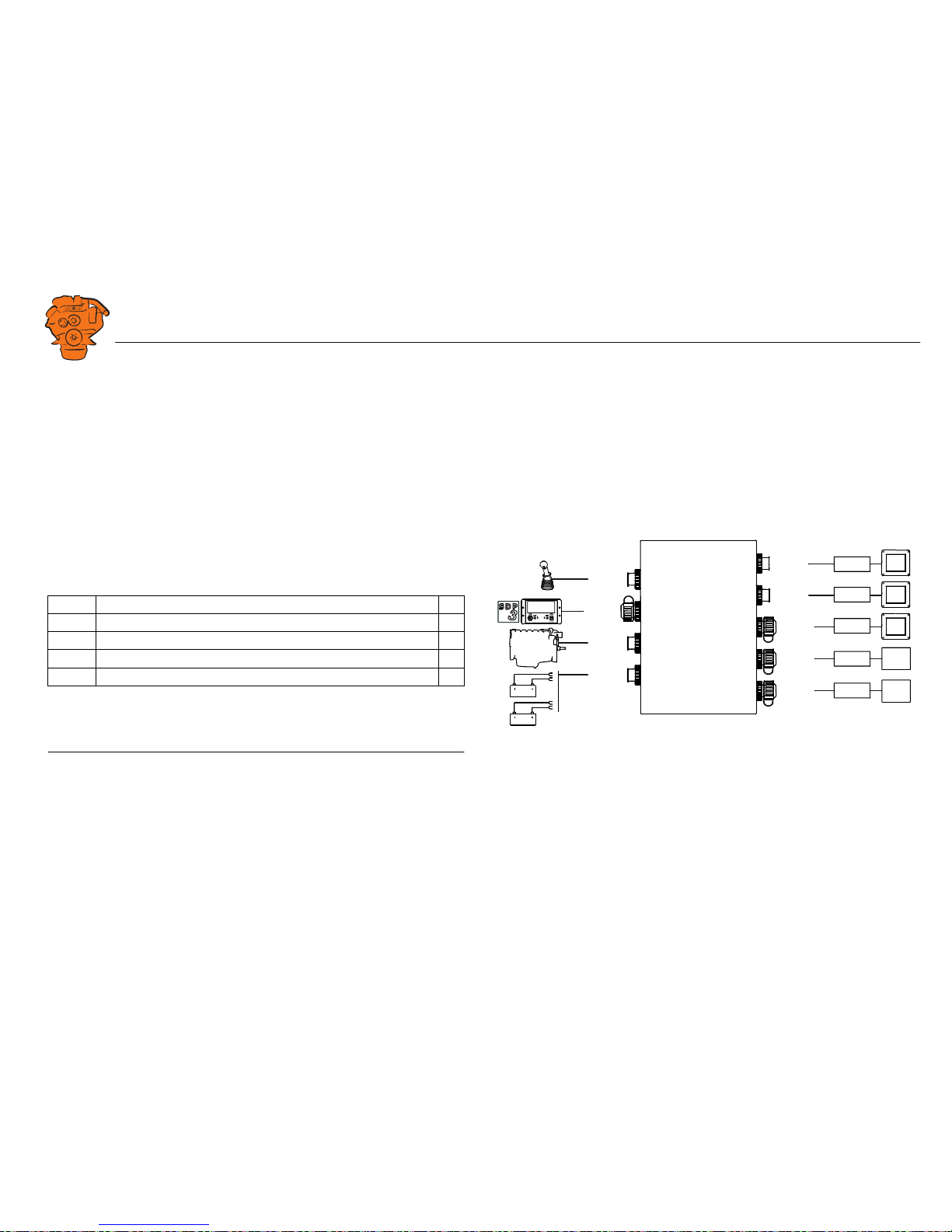
The illustration shows an overview of component parts in a marine engine management system prepared for classification.
Main display (DCU)
The main display is the basic unit of the engine management system. Different sensor
values are displayed on the main display touch screen, and different commands are
also carried out there.
The main display is configured using a computer with a web browser via the built in
web server of the main display. This is described in the Configuring the main display
via a web browser section.
Abbreviation Description
DCU Main display
RP Auxiliary display
SDU Safety device unit
FMI Failure Mode Identifier
SPN Suspect Parameter Number
361 900
Example of the layout of a type approved marine engine management system.
1. Control panel.
2. Auxiliary display (RP).
3. Network switch.
4. Main display (DCU).
5. Safety module (SDU).
6. Junction box.
7. Gateway.
Page 4
INSTALLATION
MANUAL
© Scania CV AB 2016, Sweden
System overview
03:03 Issue 5.0 en-GB 4
Auxiliary display (RP)
The auxiliary display is an option and has the same user interface as the main display.
The auxiliary display reads the configuration from the main display. This makes it
easy to retrofit.
Control panel
The engine can be started and stopped through the control panel. It can also be used
to activate and adjust engine speed settings 1 or 2. The engine installation can be carried out with or without a control panel.
Network switch
A network switch is only required if more than one auxiliary display is connected to
the engine management system. If the system only contains one auxiliary display, it
is connected directly to the main display via a crossover network cable.
Safety module (SDU)
The safety device unit has monitoring and shutdown functions and is a requirement
for classified engine management systems. It should be easily accessible so that
alarms can be acknowledged in an easy way.
Junction box
The junction box is used to connect all the parts of the engine management system to
the engine. The junction box also contains fuses. It should be easily accessible.
Gateway
The gateway reads specific messages about position and speed via NMEA 2000, so
that the instrumentation can calculate fuel consumption per nautical mile. The gateway cannot process messages other than these. The gateway requires software version 2.11 or later to be installed in the displays.
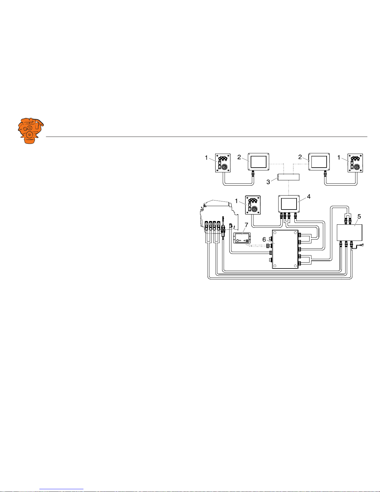
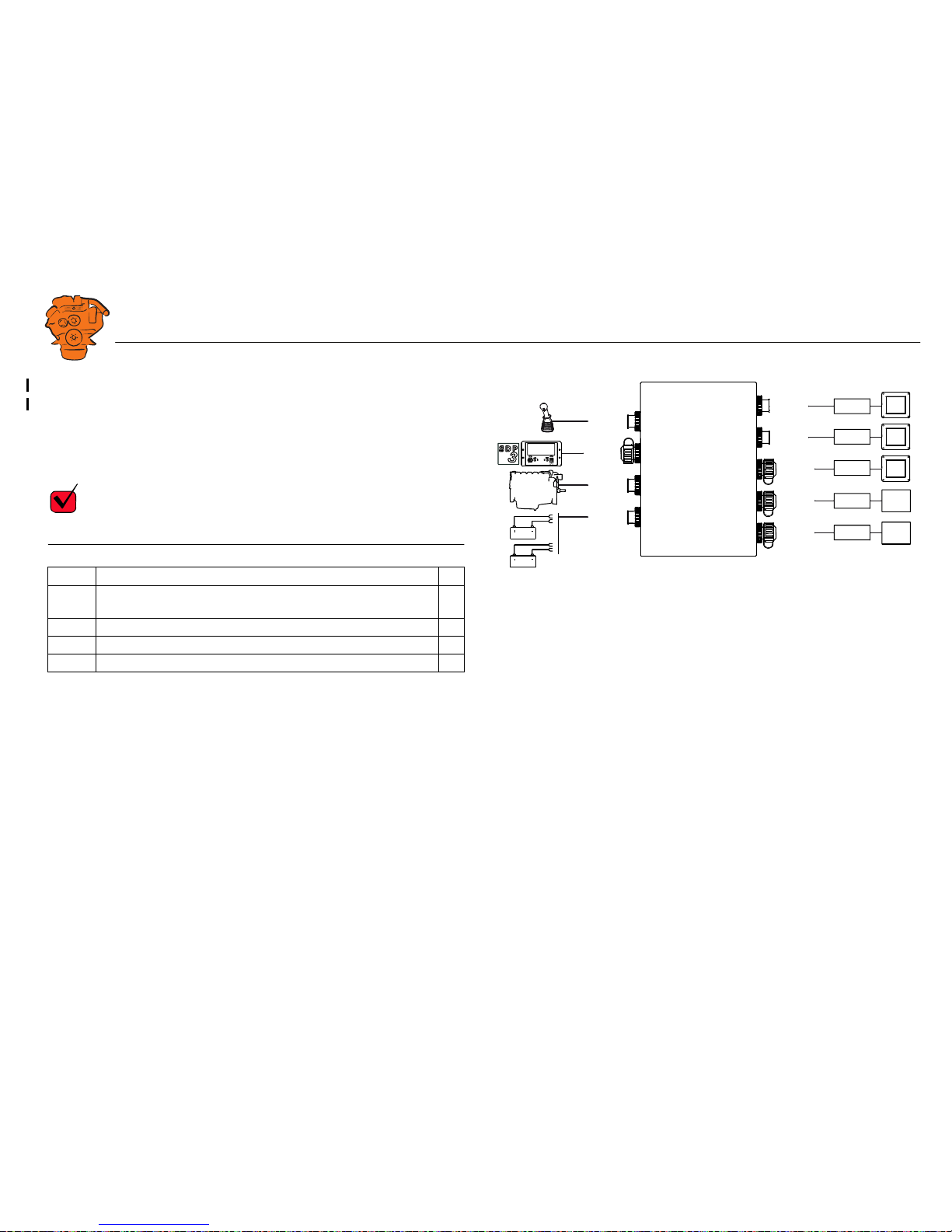
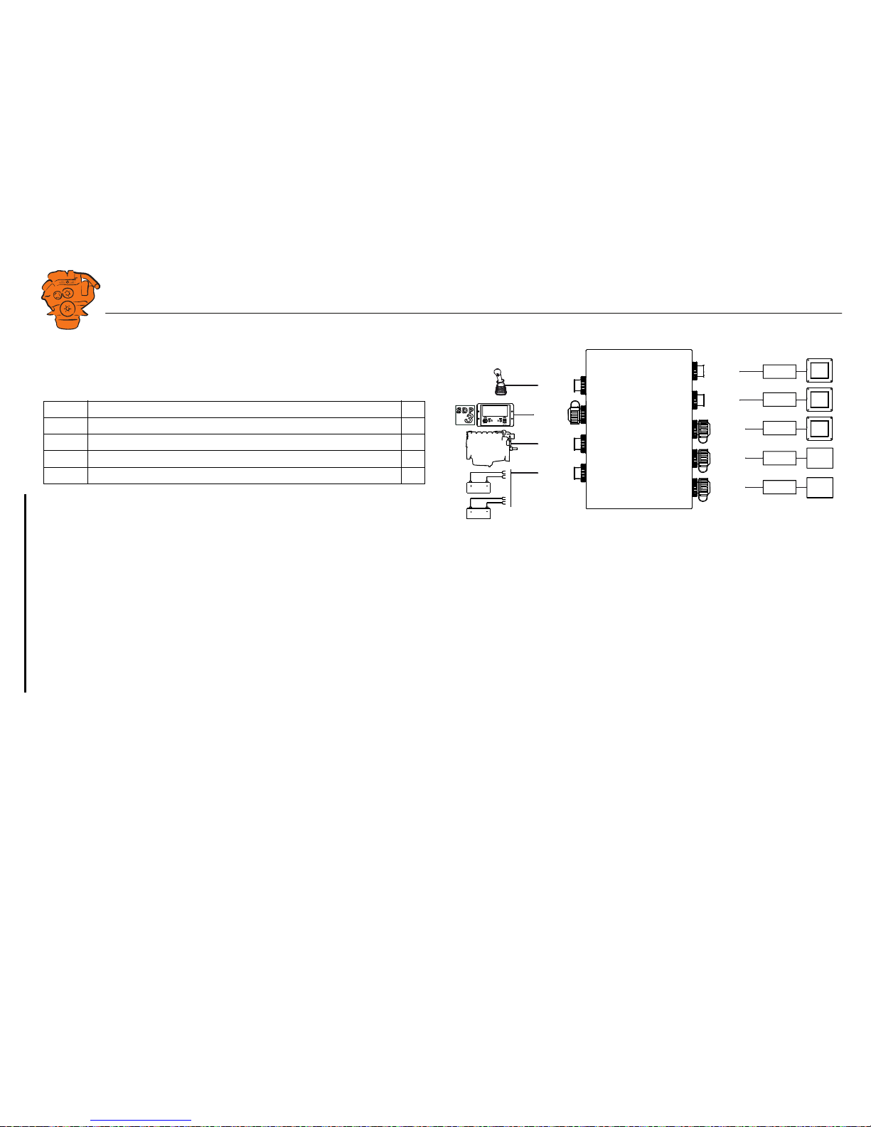
361 900
Example of the layout of a type approved marine engine management system.
1. Control panel.
2. Auxiliary display (RP).
3. Network switch.
4. Main display (DCU).
5. Safety module (SDU).
6. Junction box.
7. Gateway.
Page 5
INSTALLATION
MANUAL
© Scania CV AB 2016, Sweden
System overview
03:03 Issue 5.0 en-GB 5
Positioning of the displays
Do not position the displays so that they are exposed to direct sunlight. This impairs
the readability of the displays. The user should have full access to the displays. It
must also be easy to access the connections on the rear of the displays.
IMPORTANT!
The displays must not be fitted on vibrating equipment. They may only be positioned
next to the engine bed if either the engine or the display housing has vibration damping.
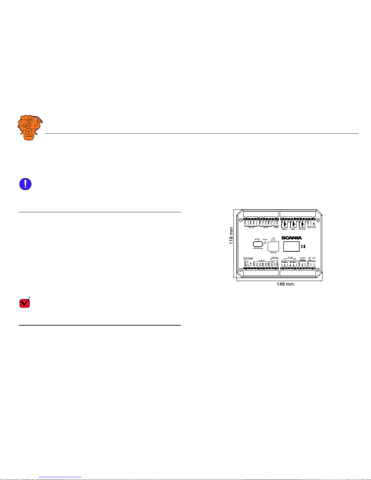
Installation dimensions
Provide a 150 x 120 mm rectangle where the display is to be positioned. There must
be at least 70 mm free space behind the display.
Main display
Scania recommends positioning the main display in the engine compartment for the
following reasons:
• To ensure that operation and monitoring are close to the engine.
• To minimise the lengths of the electrical cables between the sensors and main display.
• To reduce the risk of electrical interference caused by long electrical cables.
REQUIREMENT!
On a type approved installation, the main display must be located in the engine compartment.
361 901
Installation dimensions for the main display and auxiliary display.
Page 6

INSTALLATION
MANUAL
© Scania CV AB 2016, Sweden
System overview
03:03 Issue 5.0 en-GB 6
Auxiliary display
The auxiliary display is normally positioned outside the engine compartment, but can
also be positioned in the engine compartment.
Page 7

INSTALLATION
MANUAL
© Scania CV AB 2016, Sweden
Connection
03:03 Issue 5.0 en-GB 7
Connection
Electrical cables
To protect against electromagnetic interference, Scania recommends that all electrical cables within the system are twisted in pairs with 35-40 turns/m. This only applies
to external signal cables connected to the system.
IMPORTANT!
If a shielded electrical cable is used, the shielding should be connected to ground, not
to 0 V. Only connect the shielding to one end of the electrical cable.
To provide good separation of the electromagnetic interference that can occur, some
of the electrical cables can be routed separately from the others, e.g. the signal cable
from a magnetic pulse sensor.
Electrical cables for electric power supply must have a minimum cross section of
2.5 mm
2
.
Ground
IMPORTANT!
Separate ground and 0 V. In marine installations, ground and 0 V must not be connected. The hull is ground and the battery negative terminal is 0 V.
24 V and 0 V are filtered in the main display in order to reduce electromagnetic interference. If ground and 0 V are connected together, the filters in the main display
will not function.
Page 8
INSTALLATION
MANUAL
© Scania CV AB 2016, Sweden
Connection
03:03 Issue 5.0 en-GB 8
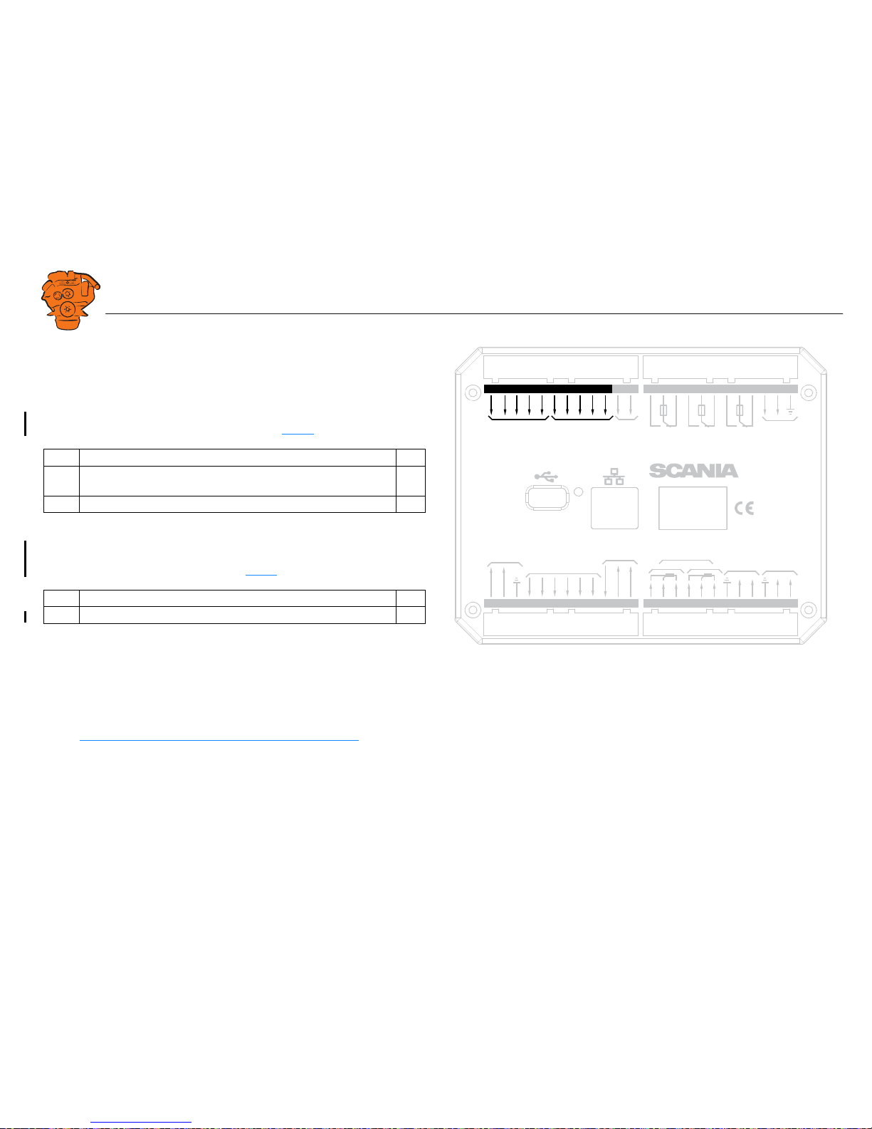
Junction box, connection
Minimum connection
The minimum connection required for the system to function is for the pins on connector C4066 to be connected. If the throttle control is to be controlled via the main
display, then pins 1 and 2 of connector C4068 must also be connected.
Please refer to the electrical system installation manual 03:01 for information on how
to connect the throttle control to the engine control unit. If the throttle control is connected to the engine control unit, secondary throttle control cannot be used.
C4066
Connection of power supply to the engine management system and instrumentation
2.0 (battery).
Note:
If the system has a safety device unit (SDU), 2 separate groups of batteries must be
used.
Pin Description I/O
1 30 voltage, 24 V -
2 Ground (battery negative terminal) -
3 30 voltage, 24 V -
4 Ground (extra battery negative terminal) -
1
2
3
4
DCU
DCU
DCU
SDU
SDU
C4068
C4067
C4052
C4053
C4056
C4058
C4059
C4054
C4055
C4057
C4060
C4061
C4062
C4066
Gateway
C4001
372 773
Connecting the junction box.
Page 9
INSTALLATION
MANUAL
© Scania CV AB 2016, Sweden
Connection
03:03 Issue 5.0 en-GB 9
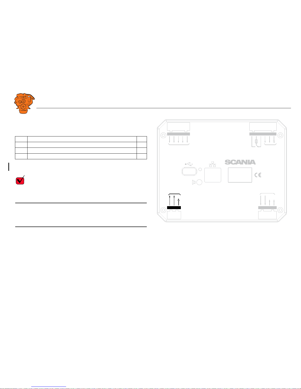
C4062
Connection to engine connector C4001.
C4067
Diagnostic socket for connecting e.g. SDP3 and CAN communication. Use connector 1 508 055 and hand crimping tool 99 494.
REQUIREMENT!
Any equipment connected to the connector must comply with the CAN specification.
Pin Description I/O
1 15 voltage: 24 V after fuse F4005 and relay in the junction box. Con-
trolled by the system being active.
-
2Ground -
3CAN high -
4CAN low -
1
2
3
4
DCU
DCU
DCU
SDU
SDU
C4068
C4067
C4052
C4053
C4056
C4058
C4059
C4054
C4055
C4057
C4060
C4061
C4062
C4066
Gateway
C4001
372 773
Connecting the junction box.
Page 10
INSTALLATION
MANUAL
© Scania CV AB 2016, Sweden
Connection
03:03 Issue 5.0 en-GB 10
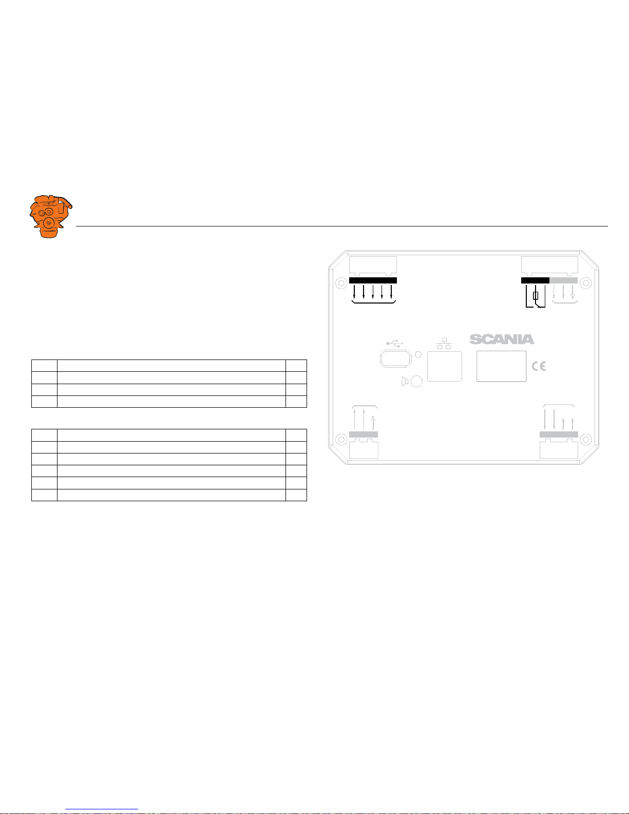
C4068
Connecting the incoming throttle actuation signal. The update frequency is 100 Hz,
with a median filter on 3 readings.
C4052
Connection to main display via C4054.
C4053
Connection to main display via C4055.
C4056
Connection to main display via C4057.
C4058
Connection to safety device unit (SDU) via C4060.
C4059
Connection to safety device unit (SDU) via C4061.
Pin Description I/O
1 24 V (0.2 A), voltage supply to passive throttle control O
2 Input for signal from throttle control, 4-20 mA I
3 Not used -
4 Not used -
1
2
3
4
DCU
DCU
DCU
SDU
SDU
C4068
C4067
C4052
C4053
C4056
C4058
C4059
C4054
C4055
C4057
C4060
C4061
C4062
C4066
Gateway
C4001
372 773
Connecting the junction box.
Page 11
INSTALLATION
MANUAL
© Scania CV AB 2016, Sweden
Connection
03:03 Issue 5.0 en-GB 11
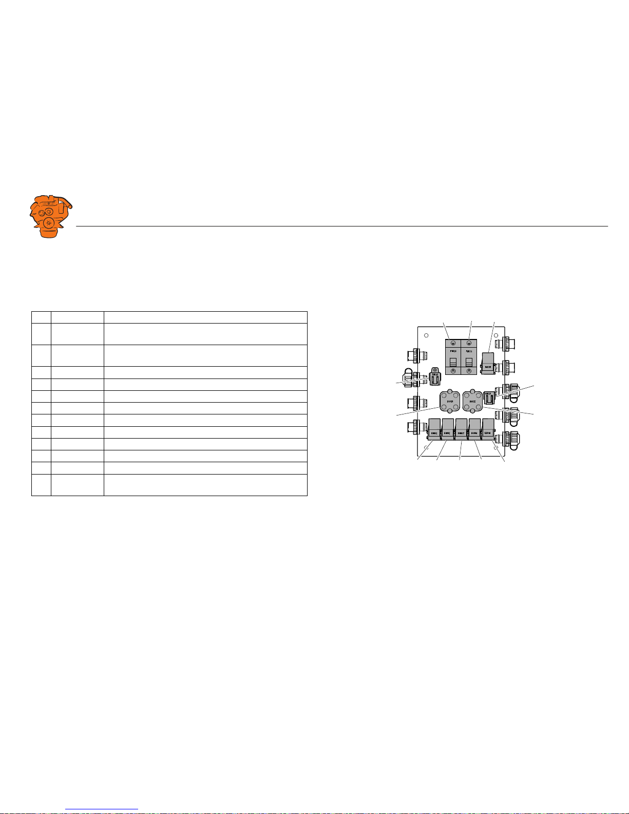
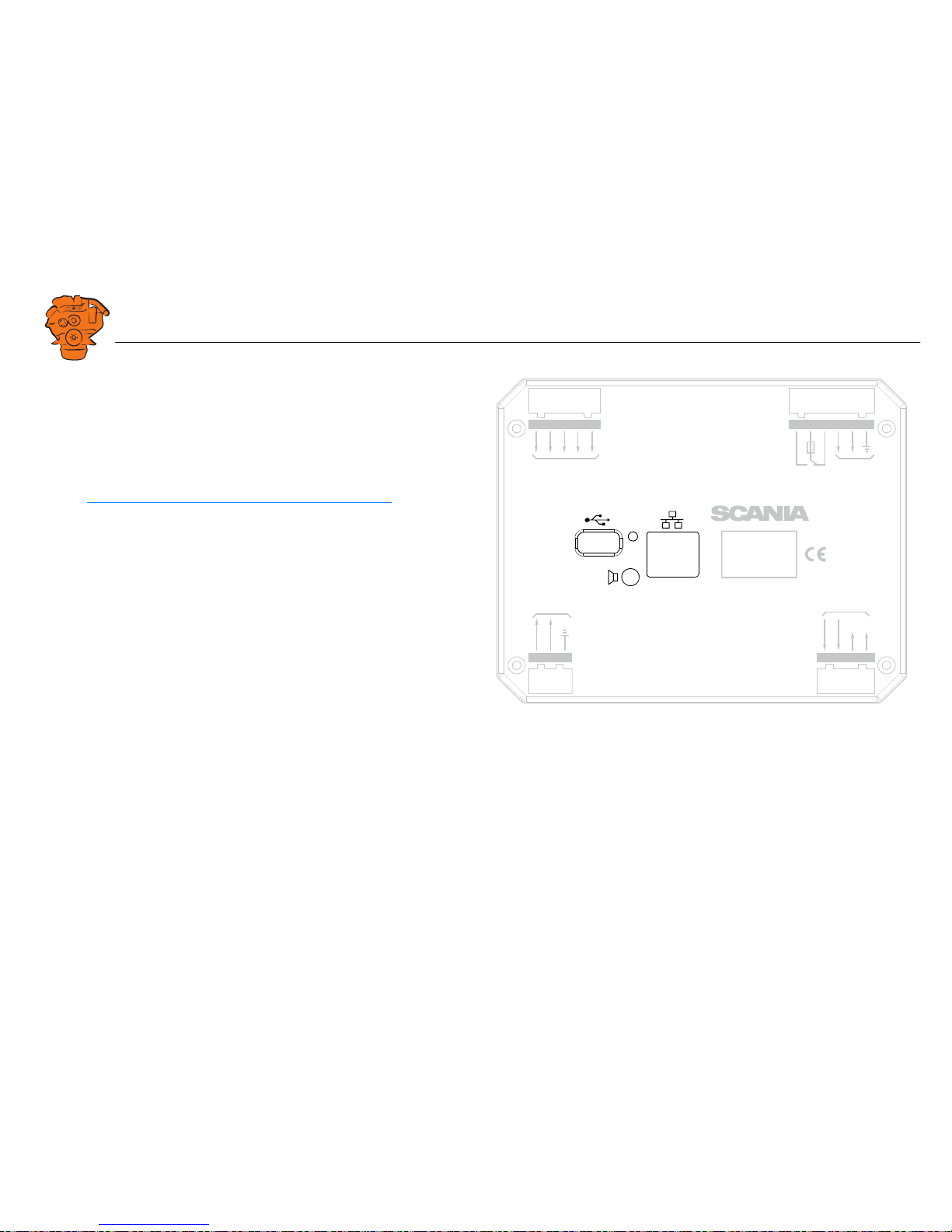
Junction box, components
There are two 20 A miniature circuit breakers in the junction box, one for each battery connection. Depending on the cable length, it may be necessary to fit extra fuses
for the electrical cable. The junction box also has a number of blade fuses, diodes and
relays as described below.
Designation Description
1 F4010 20 A miniature circuit breaker for incoming voltage from bat-
tery group, main supply
2 F4011 20 A miniature circuit breaker for incoming voltage from bat-
tery group, redundant supply
3 R4005 Relay for 15 voltage
4 F4013 2 x 2 A blade fuses for auxiliary socket
5 D4017 Diode to separate the battery groups, ground
6 D4018 Diode to request shutdown/activation of 15 voltage
7 R4004 Relay for engine shutdown (15 voltage)
8 R4003 Relay for engine shutdown (30 voltage)
9 R4002 Relay for detecting loss of redundant battery group
10 R4001 Relay for detecting loss of main battery group
11 D4016 Diode to separate the battery groups (30 voltage)
12 F4012 2 x 20 A blade fuses for engine control unit, 2 x 5 A blade
fuses for internal supply to panels
347 887
123
4
5
10
9876
12
11
Components in the junction box.
Page 12

INSTALLATION
MANUAL
© Scania CV AB 2016, Sweden
Connection
03:03 Issue 5.0 en-GB 12
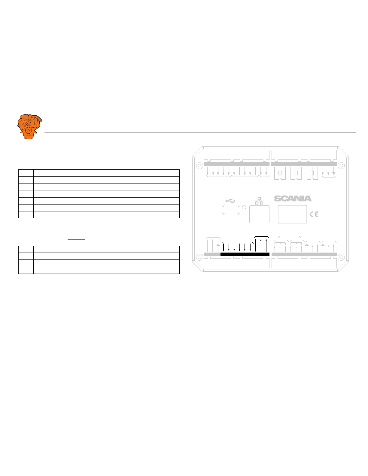
Main display (DCU), junction blocks
The only connection needed for the system to work is for the main display connector
to be connected and the main display to be connected to the junction box via junction
box connectors C4052, C4053 and C4056. See System overview
.
The connections on the main display are listed on the following pages.
Electric power supply: junction block 1-3
The system is designed for a voltage of 24 V.
REQUIREMENT!
Connect the display directly to the battery and not to the starter motor. Use twisted
pair electrical cables and do not make the electrical cable longer than necessary. The
cable cross-sectional area must be at least 2.5 mm².
Alarm at low voltage
There is a 30 second delay before the alarm or warning is activated.
Description I/O
1 24 V main power supply I
2 0 V main power supply I
3 Ground connection I
Warning < 21 V
Alarm < 18 V
0V
Out 1
12 / 24V
Out 3
Out 4
Out 5
Out 6
L
H
L
H
USB Memor
y
Powe
r
Out 2
Pic
kup
H
L
CAN J1939
All Faults
NO
NC
Rela
y 1
NO
NC
Rela
y 2
NO
NC
In 5
A
B
In 1
In 2
In 3
In 4
Inputs
Outputs
1A
1A
1A
Pow
er Supply
Ether
net
C
C
C
RIO / SDU
Link
RS-485
Modb
us
24V 0.2A
Ch. 1Ch.
2
4-20 mA
A
B
C
1
PT100
2
A
B
C
Key set
123456789
10 11 12 13 14 15 16 17 18 19 20 21 22 23 24
36 35 34 33 32 31 30 29 28 2 7 26 2548 47 46 45 44 43 42 41 40 39 38 37
347 812
Junction blocks on the main display.
Page 13
INSTALLATION
MANUAL
© Scania CV AB 2016, Sweden
Connection
03:03 Issue 5.0 en-GB 13
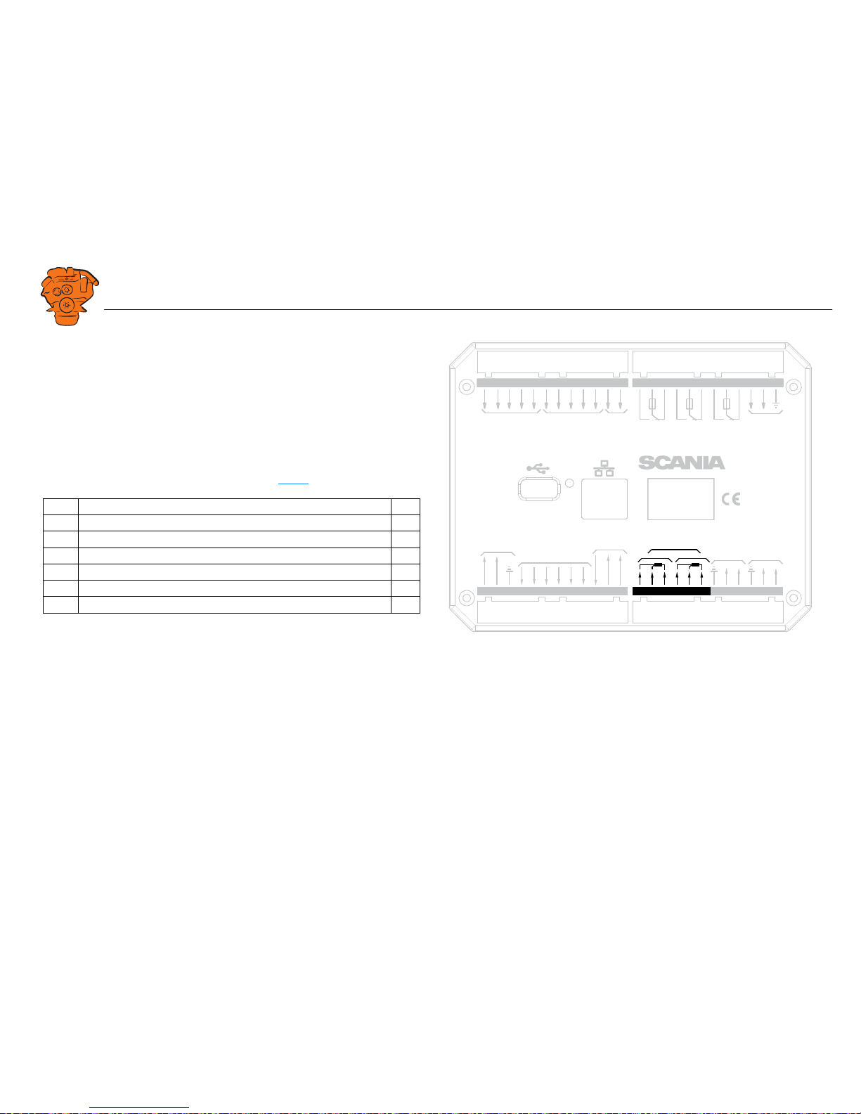
Change-over output: junction block 4-9
The main display has six 24 V outputs that can be configured individually for optional functions or events. See the 12/24V Output Functions
section.
4-20 mA input: junction block 10-12
The main display has two configurable analogue inputs. Information on how to configure the inputs is in the 4-20 mA
section.
If the signal is outside the following limit values, a warning is displayed on the display.
• Less than 2 mA: defective
• Over 24 mA: short circuit
2-4 mA is treated as 4 mA and 20-22 mA is treated as 20 mA. The updating frequency is 2 Hz.
Description I/O
4 24 V output #1 (0.5 A shared with output #2) O
5 24 V output #2 (0.5 A shared with output #1) O
6 24 V output #3 (0.2 A) O
7 24 V output #4 (0.2 A) O
8 24 V output #5 (0.2 A) O
9 24 V output #6 (0.2 A) O
Description I/O
10 24 V supply (0.2 A). The junction block is occupied O
11 4-20 mA input #1 I
12 4-20 mA input #2 I
0V
12 / 24V
L
H
L
H
USB Memor
y
Powe
r
Pic
kup
H
L
CAN J1939
All Faults
NO
NC
Rela
y 1
NO
NC
Rela
y 2
NO
NC
In 5
A
B
In 1
In 2
In 3
In 4
Inputs
1A
1A
1A
Pow
er Supply
Ether
net
C
C
C
RIO / SDU
Link
RS-485
Modb
us
Out 1
Out 3
Out 4
Out 5
Out 6
Out 2
Outputs
24V 0.2A
Ch. 1Ch.
2
4-20 mA
A
B
C
1
PT100
2
A
B
C
Key set
123456789
10 11 12 13 14 15 16 17 18 19 20 21 22 23 24
36 35 34 33 32 31 30 29 28 27 26 2548 47 46 45 44 43 42 41 40 39 38 37
347 813
Junction blocks on the main display.
Page 14
INSTALLATION
MANUAL
© Scania CV AB 2016, Sweden
Connection
03:03 Issue 5.0 en-GB 14
PT100 input: junction block 13-18
There are two PT100 inputs in the main display. The inputs are adapted for PT100
sensors with 2 or 3 electrical cables. Connect the electrical cables as follows:
2 wire PT100: Bridge A and B. Connect one wire to AB and the other to C.
3 wire PT100: Connect A to A, B to B and C to C.
4 wire PT100: Connect in the same way as 3 wire PT100, but note that the fourth
wire, D, should not be connected. It should hang loose or, if necessary, be cut off.
Information on how to configure the inputs is in the PT100
section.
If the signal is outside the following limit values, a warning is displayed on the display.
The updating frequency is 2 Hz.
Description I/O
13 PT100 #1 A I
14 PT100 #1 B I
15 PT100 #1 C I
16 PT100 #2 A I
17 PT100 #2 B I
18 PT100 #2 C I
Below 90
ohms
short circuit
Above 390
ohms
defective
0V
12 / 24V
L
H
L
H
USB Memor
y
Powe
r
Pic
kup
H
L
CAN J1939
All Faults
NO
NC
Rela
y 1
NO
NC
Rela
y 2
NO
NC
In 5
A
B
In 1
In 2
In 3
In 4
Inputs
1A
1A
1A
Pow
er Supply
Ether
net
C
C
C
RIO / SDU
Link
RS-485
Modb
us
Out 1
Out 3
Out 4
Out 5
Out 6
Out 2
Outputs
24V 0.2A
Ch. 1Ch.
2
4-20 mA
A
B
C
1
PT100
2
A
B
C
Key set
123456789
10 11 12 13 14 15 16 17 18 19 20 21 22 23 24
36 35 34 33 32 31 30 29 28 27 26 2548 47 46 45 44 43 42 41 40 39 38 37
369 835
Junction blocks on the main display.
Page 15
INSTALLATION
MANUAL
© Scania CV AB 2016, Sweden
Connection
03:03 Issue 5.0 en-GB 15
Modbus RTU, RS-485: junction block 19-21
The main display has a built-in ModbusTM interface, on both RS-485 and Ethernet.
The latter can also be designated Modbus TCP.
RIO link: junction block 22-24
Not used.
J1939 CAN interface: junction block 25-27
Connection to engine control unit via CAN. The connection is terminated.
Description I/O
19 Shielded I
20 Low I
21 High I
Description I/O
25 Not used I
26 Low I
27 High I
0V
12 / 24V
L
H
L
H
USB Memor
y
Powe
r
Pic
kup
H
L
CAN J1939
All Faults
NO
NC
Rela
y 1
NO
NC
Rela
y 2
NO
NC
In 5
A
B
In 1
In 2
In 3
In 4
Inputs
1A
1A
1A
Pow
er Supply
Ether
net
C
C
C
RIO / SDU
Link
RS-485
Modb
us
Out 1
Out 3
Out 4
Out 5
Out 6
Out 2
Outputs
24V 0.2A
Ch. 1Ch.
2
4-20 mA
A
B
C
1
PT100
2
A
B
C
Key set
123456789
10 11 12 13 14 15 16 17 18 19 20 21 22 23 24
36 35 34 33 32 31 30 29 28 27 26 2548 47 46 45 44 43 42 41 40 39 38 37
369 836
Junction blocks on the main display.
Page 16
INSTALLATION
MANUAL
© Scania CV AB 2016, Sweden
Connection
03:03 Issue 5.0 en-GB 16
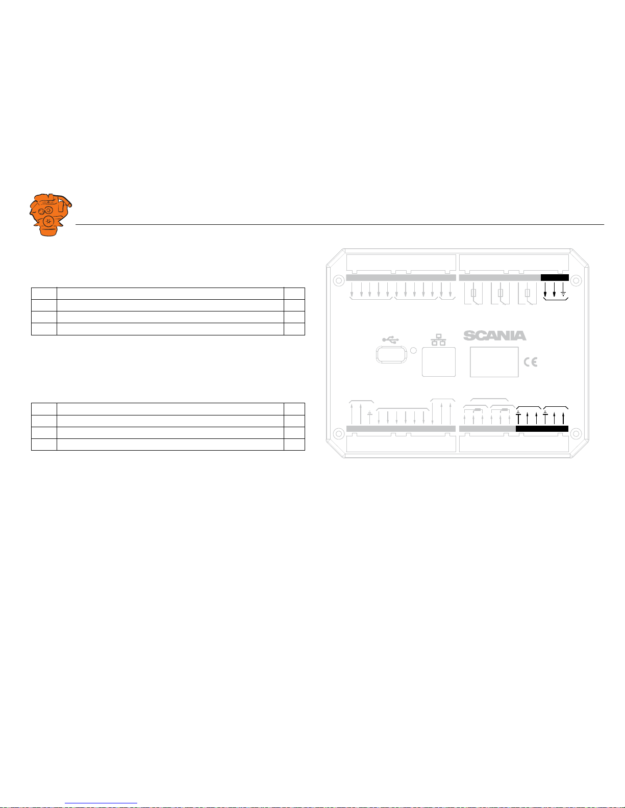
Relay for all faults: junction block 28-30
The relay is activated when there are no active faults and is deactivated when a fault
occurs. Every new event is counted as a fault in the alarm list, except diagnostics
messages with a white ranking. The relay can be used to switch on an external lamp
or emit an acoustic signal, for example.
Relay #1: junction block 31-33
The relay can be configured so that it is activated for any of the built in functions. See
the Relay Functions
section.
Description I/O
28 NC (1 A) -
29 C (1 A) -
30 NO (1 A) -
Description I/O
31 NC (1 A) -
32 C (1 A) -
33 NO (1 A) -
0V
12 / 24V
L
H
L
H
USB Memor
y
Powe
r
Pic
kup
H
L
CAN J1939
All Faults
NO
NC
Rela
y 1
NO
NC
Rela
y 2
NO
NC
In 5
A
B
In 1
In 2
In 3
In 4
Inputs
1A
1A
1A
Pow
er Supply
Ether
net
C
C
C
RIO / SDU
Link
RS-485
Modb
us
Out 1
Out 3
Out 4
Out 5
Out 6
Out 2
Outputs
24V 0.2A
Ch. 1Ch.
2
4-20 mA
A
B
C
1
PT100
2
A
B
C
Key set
123456789
10 11 12 13 14 15 16 17 18 19 20 21 22 23 24
36 35 34 33 32 31 30 29 28 27 26 2548 47 46 45 44 43 42 41 40 39 38 37
369 838
Junction blocks on the main display.
Page 17

INSTALLATION
MANUAL
© Scania CV AB 2016, Sweden
Connection
03:03 Issue 5.0 en-GB 17
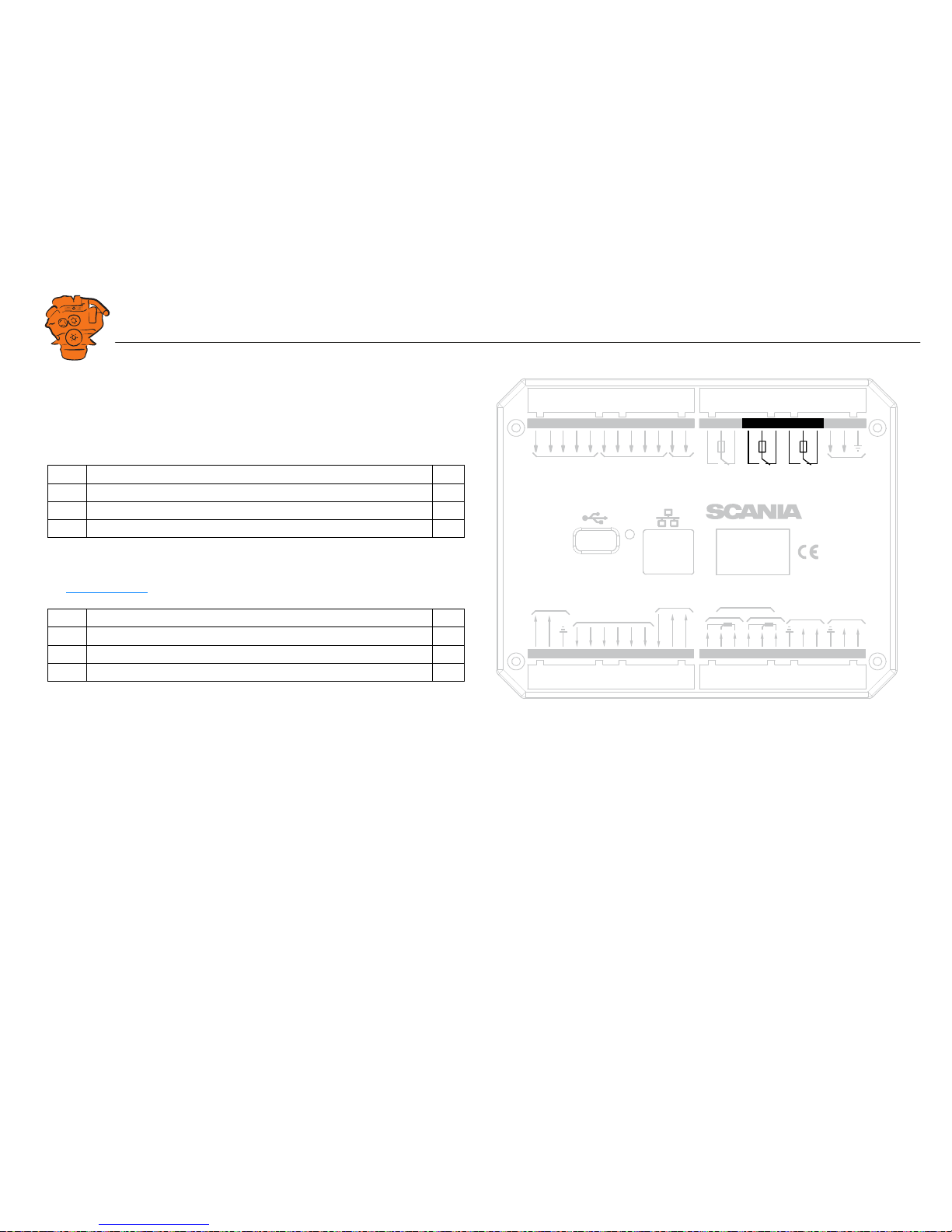
Relay #2: junction block 34-36
The relay can be configured so that it is activated for any of the built in functions. See
the Relay Functions
section.
Input for magnetic pulse sensor: junction block 37-38
An auxiliary rotational speed sensor is connected here. Only shield the electrical cable on the sensor side. Information on configuration is in the Local Pickup
section.
Description I/O
34 NC (1 A) -
35 C (1 A) -
36 NO (1 A) -
Description I/O
37 A I
38 B I
0V
12 / 24V
L
H
USB Memor
y
Powe
r
In 5
In 1
In 2
In 3
In 4
Inputs
Pow
er Supply
Ether
net
Pic
kup
Rela
y 2
NO
NC
A
B
1A
C
H
L
CAN J1939
All Faults
NO
NC
Rela
y 1
NO
NC
1A
1A
C
C
RIO / SDU
Link
Out 1
Out 3
Out 4
Out 5
Out 6
Out 2
Outputs
24V 0.2A
Ch. 1Ch.
2
4-20 mA
L
H
RS-485
Modb
us
A
B
C
1
PT100
2
A
B
C
Key set
123456789
10 11 12 13 14 15 16 17 18 19 20 21 22 23 24
36 35 34 33 32 31 30 29 28 27 26 2548 47 46 45 44 43 42 41 40 39 38 37
347 816
Junction blocks on the main display.
Page 18
INSTALLATION
MANUAL
© Scania CV AB 2016, Sweden
Connection
03:03 Issue 5.0 en-GB 18
Change-over input: junction block 39-43
There are five 24 V inputs that can be configured individually for available functions.
For example, a low oil pressure sensor can be connected, or the input can be configured to activate a built in function such as automatic start.
If there is a safety device unit (SDU) in the system, three of the inputs are reserved.
Information on how to configure the inputs is in the Switch
section.
Connection of control panel. junction block 44-48
If there is no control panel in the system, inputs 44-48 can also be configured. However, this only applies if the software version of the display is 2.12 or later. Information on how to configure the inputs is in the Switch
section.
Ethernet (Modbus TCP)
The main display is connected to the LAN or directly to a computer via a standard
CAT-5 network. Connect to port RJ45 via a crossover network cable. The IP address
in the main display or the computer may need to be changed in order to configure the
main display via a web browser.
USB input
See the Configuring and upgrading software with USB memory stick section.
Description I/O
39-41 24 V inputs. The inputs are reserved if there is a safety device unit in
the system.
I
42-43 24 V inputs, configurable. I
Description I/O
44-48 24 V inputs. Reserved in systems with control panel. I
0V
12 / 24V
L
H
USB Memor
y
Powe
r
Inputs
Pow
er Supply
Ether
net
Pic
kup
Rela
y 2
NO
NC
A
B
1A
C
H
L
CAN J1939
All Fau lts
NO
NC
Rela
y 1
NO
NC
1A
1A
C
C
RIO / SDU
Link
Out 1
Out 3
Out 4
Out 5
Out 6
Out 2
Outputs
24V 0.2A
Ch. 1Ch.
2
4-20 mA
L
H
RS-485
Modb
us
A
B
C
1
PT100
2
A
B
C
In 5
In 1
In 2
In 3
In 4
Key set
123456789
10 11 12 13 14 15 16 17 18 19 20 21 22 23 24
36 35 34 33 32 31 30 29 28 27 26 2548 47 46 45 44 43 42 41 40 39 38 37
347 817
Junction blocks on the main display.
Page 19
INSTALLATION
MANUAL
© Scania CV AB 2016, Sweden
Connection
03:03 Issue 5.0 en-GB 19
Auxiliary display (RP), junction blocks
Electric power supply: junction block 1-3
The auxiliary display must have a separate electric power supply. The system is designed for a voltage of 24 V.
REQUIREMENT!
Connect the display directly to the battery and not to the starter motor. Use twisted
pair electrical cables and do not make the electrical cables longer than necessary. The
cable cross-sectional area must be at least 2.5 mm².
Note:
Scania recommends connecting the auxiliary display to the same fuse group as the
main display.
Alarm at low voltage
There is a 30 second delay before an alarm or warning is activated.
Description I/O
1 24 V main power supply I
2 0 V main power supply I
3 Ground connection I
Warning < 21 V
Alarm < 18 V
0V
12 / 24V
123
21 22 23 24
L
H
USB Memor
y
Powe
r
Pow
er Supply
Ether
net
30 29 28 27 26 25
H
L
CAN J1939
All Faults
NO
NC1AC
RIO / SDU Link
0V
12 / 24V
A
udio
Line Out
48 47 46 45 44
Key set
347 825
Junction blocks on the auxiliary display.
Page 20
INSTALLATION
MANUAL
© Scania CV AB 2016, Sweden
Connection
03:03 Issue 5.0 en-GB 20
RIO link: junction block 21-24
Not used.
J1939 CAN interface: junction block 25-27
Not used. The connection is terminated.
Relay for all faults: junction block 28-30
The relay is activated when there are no active faults and is deactivated when a fault
occurs. Every new event is counted as a fault in the alarm list, except diagnostics
messages with a white ranking.
Connection of control panel. junction block 44-48
Description I/O
28 NC -
29 C -
30 NO -
Description I/O
44 24 V input #6. Reserved for the control panel I
45 24 V input #7. Reserved for the control panel I
46 24 V input #8. Reserved for the control panel I
47 24 V input #9. Reserved for the control panel I
48 24 V input #10. Reserved for the control panel I
0V
12 / 24V
123
21 22 23 24
L
H
USB Memor
y
Powe
r
Pow
er Supply
Ether
net
30 29 28 27 26 25
H
L
CAN J1939
All Faults
NO
NC1AC
RIO / SDU Link
0V
12 / 24V
A
udio
Line Out
48 47 46 45 44
Key set
347 823
Junction blocks on the auxiliary display.
Page 21
INSTALLATION
MANUAL
© Scania CV AB 2016, Sweden
Connection
03:03 Issue 5.0 en-GB 21
Ethernet (Modbus TCP)
Connection to the LAN.
USB input
See the Configuring and upgrading software with USB memory stick section.
Loudspeaker output
The auxiliary display has a standard output of 3.5 mm for the connection of regular
computer speakers. The installation will then have more sounds than just the built in
buzzer, and different types of sound can be linked with different events. This is how
to activate external speakers:
• In the auxiliary display, go to Menu > Settings > Sound.
• Activate the Speakers option with the Sound Configuration button.
0V
12 / 24V
123
21 22 23 24
L
H
USB Memor
y
Powe
r
Pow
er Supply
Ether
net
30 29 28 27 26 25
H
L
CAN J1939
All Faults
NO
NC1AC
RIO / SDU Link
0V
12 / 24V
A
udio
Line Out
48 47 46 45 44
Key set
347 824
Junction blocks on the auxiliary display.
Page 22
INSTALLATION
MANUAL
© Scania CV AB 2016, Sweden
Connection
03:03 Issue 5.0 en-GB 22
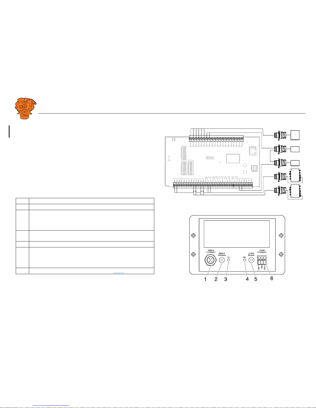
Safety module (SDU), connection
The illustration shows the safety device unit connections.
Gateway – overview
Pos. Description
1 Connection to the ship NMEA 2000 network.
2 "NMEA Instance" rotary control. Set the instance which the gateway trans-
mits to other units. Used if 2 or more gateways are connected to the same
NMEA 2000 network. In such a case, make sure that each gateway has a
unique instance, e.g. "0" and "1".
3 Blue "Tx" LED, indicates that data is being received from NMEA 2000
every 2.5 seconds.
4 Green "Rx" LED, indicates that data is being sent to J1939.
5 "J1939 Source" rotary control. Set the instance for the NMEA 2000 GPS
which the information should be loaded from. If the gateway does not receive any signals from a GPS with the selected instance within 30 seconds,
all valid GPS data is transferred automatically.
6 Connection to connector C4067 junction box. See C4067
.
SWITCH 1
SWITCH 2
SWITCH 3
SWITCH 4
SWITCH 5
SWITCH 6
SWITCH 7
SWITCH 8
SWITCH 1
SWITCH 2
SWITCH 3
SWITCH 4
SWITCH 5
SWITCH 6
SWITCH 7
SWITCH 8
SHUTDOWNFAULT
SWITCH 1 SWITCH 2 SWITCH 3 SWITCH 4 SWITCH 5 SWITCH 6 SWITCH 7 SWITCH 8
STA
TUS
PO
WER
CRANK CUTOFF
R
UNNING
TACHO 1
TACHO 2
SHUTDOWN OVERRIDE
B
UZZER
COM 1
COM 2
COM 3
SHUTDOWN
O
VERRIDE
A
CKNOWLEDGE
COM 3
CONFIGURATION
ETHERNET
shutdown unit
RELEASE
SHUTDOWN
O
VERSPEED
SHUTD
O
WN COIL
SHUTD
O
WN OVERIDE
SHUTDOWN
CRANK
CUTOFFBUZZLERFA
ULT R
UNNING
COM 1
DCU LINK
COM 2
RS 485
MODBUS RTU
ACKNOWLEDGE
OVERSPEED
TEST
COM 4
USB
TACHO 2
TACHO 1
S
H
U
T
D
O
W
N
C
O
I
L
S
U
P
P
L
Y
1 24V
4 24V
6 24V
20V
70V
50V38
34353637383940414243421
422
423
424
425
42650515253
9101112131415161718192021222324252627282930313233
H
L
H
L
C4063
T4003
T4004
C4064
T4006
T4007
T4006
T4007
C4058
C4059
C4074
C4060
C4061
C4065
372 772
361 902
Page 23
INSTALLATION
MANUAL
© Scania CV AB 2016, Sweden
Connection
03:03 Issue 5.0 en-GB 23
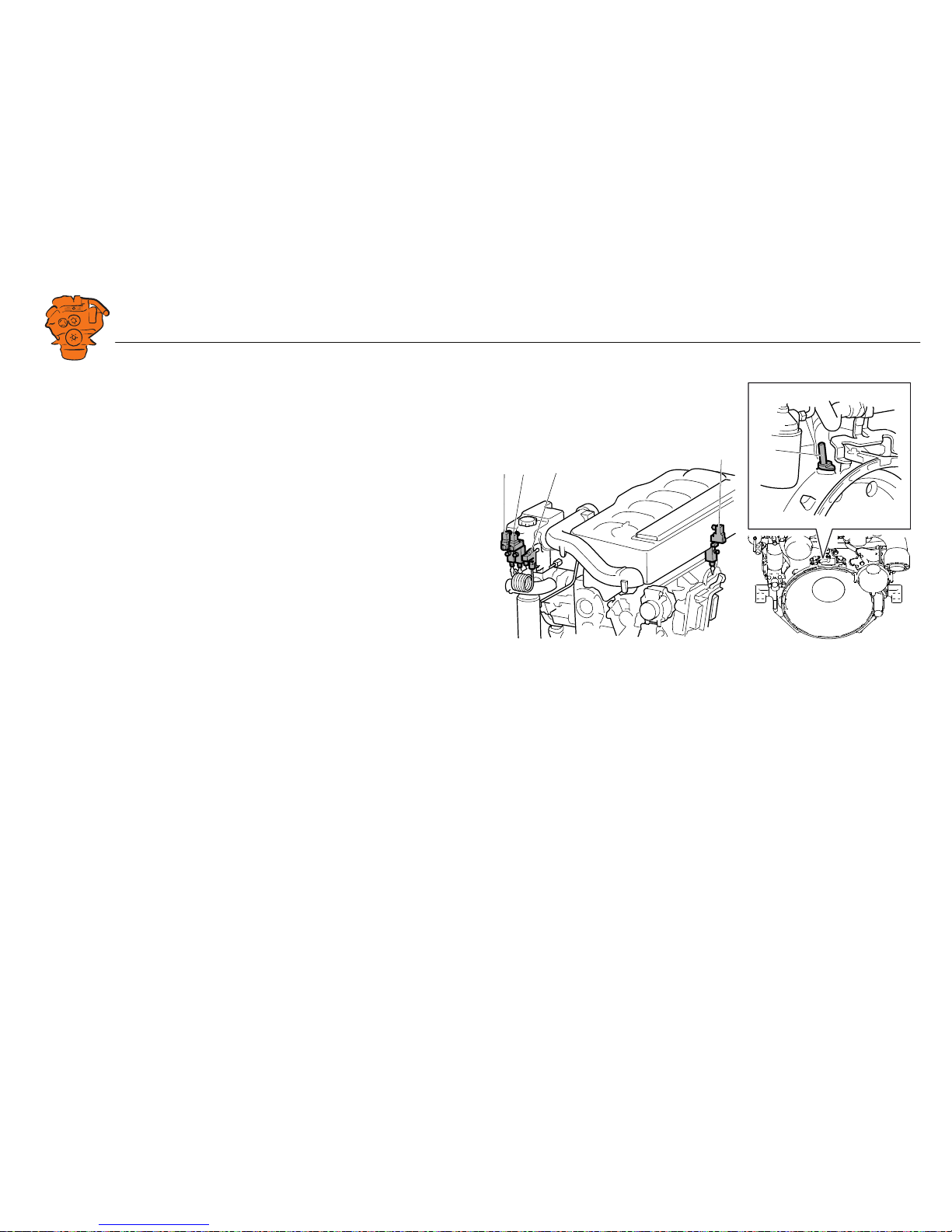
Position of the monitors on the engine
The illustration shows the position of the monitors on DI09 and DI13.
See 02:01 Engine for information on where to connect external monitoring sensors.
1
5
2
4
3
347 830
DI09, DI13.
1. Coolant pressure monitor, T4006.
2. Oil pressure monitor, T4003.
3. Coolant temperature monitor, T4004.
4. Fuel pressure monitor, T4007.
5. Engine speed monitor, T4005.
Page 24
INSTALLATION
MANUAL
© Scania CV AB 2016, Sweden
Connection
03:03 Issue 5.0 en-GB 24
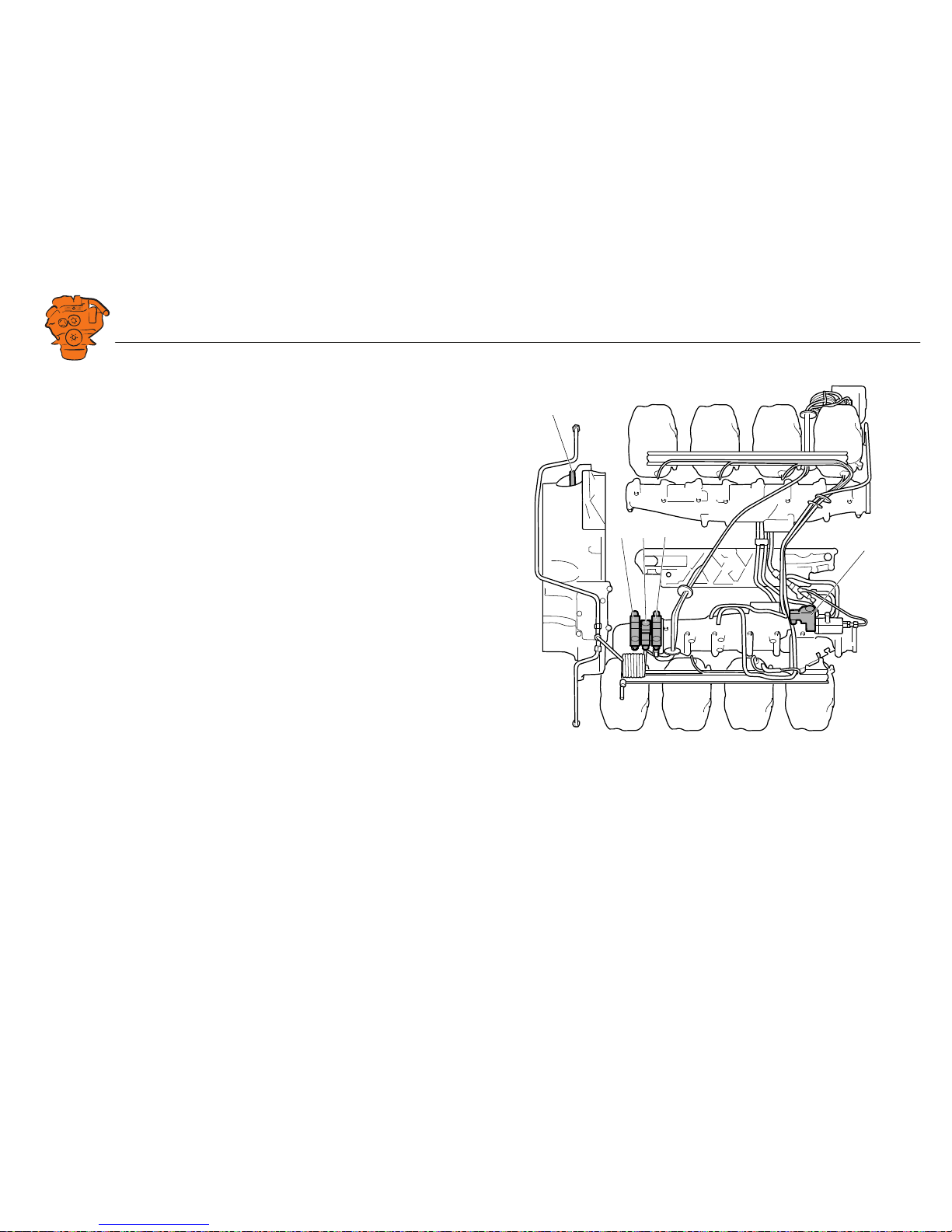
The illustration shows the location of the monitors on DI16.
See 02:01 Engine for information on where to connect external monitoring sensors.
5
2
43
1
347 831
DI16.
1. Engine speed monitor, T4005.
2. Oil pressure monitor, T4003.
3. Coolant temperature monitor, T4004.
4. Coolant pressure monitor, T4006.
5. Fuel pressure monitor, T4007.
Page 25
INSTALLATION
MANUAL
© Scania CV AB 2016, Sweden
Connection
03:03 Issue 5.0 en-GB 25
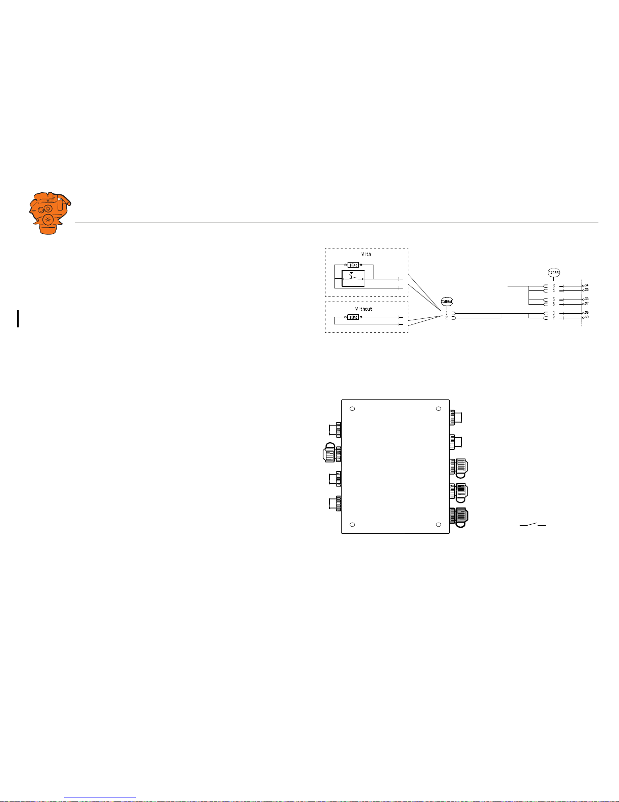
Connecting emergency stop
It is possible to connect an emergency stop which disconnects the voltage to the engine control unit. The connection is made in different ways, depending on whether
the system has a safety device unit (SDU) or not.
System with safety device unit (SDU)
Connect a switch with a 10 kohms resistor to connector C4064 in cable harness connected to the safety device unit.
System without safety device unit (SDU)
Connect a regular open switch to pin 3 in connector C4059 in the junction box. The
switch should be connected to 24 V.
Use connector 2 131 199 and the following tools:
• Hand crimping tool 99 494
• Hand crimping tool 99 491
347 885
SDU
System with safety device unit: connection of emergency stop to C4064.
+24V
C4059-3
347 886
System without safety device unit: connecting an emergency stop to the junction box.
Page 26
INSTALLATION
MANUAL
© Scania CV AB 2016, Sweden
Connection
03:03 Issue 5.0 en-GB 26
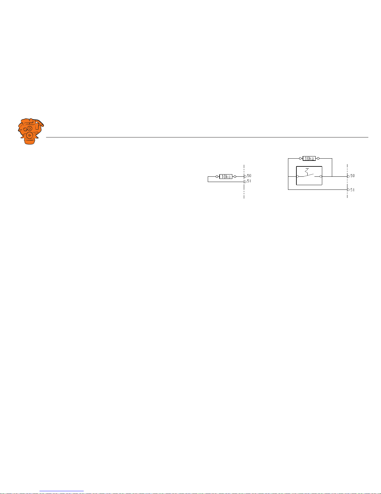
Engine shutdown override in systems with safety
device unit (SDU)
It is possible to override engine shutdown requested by the safety device unit in systems prepared for classification. Proceed as follows:
1. Remove the existing 10 kohms resistor between junction blocks 50 and 51 in the
safety device unit.
2. Connect a switch with a 10 kohms resistor between junction blocks 50 and 51.
SDU
347 888
SDU
12
Overriding engine shutdown requested by the safety device unit.
Page 27

INSTALLATION
MANUAL
© Scania CV AB 2016, Sweden
Using the main display
03:03 Issue 5.0 en-GB 27
Using the main display
First start
When you start the main display for the first time or have performed a factory reset,
a power-on wizard is displayed. All settings made in the wizard can also be made at
a later stage. The first power-on wizard contains the following steps:
1. Calibrate Touch
Calibrate the display by pressing the 5 marks which are displayed one after another.
The calibration must be performed correctly in order to continue with the wizard.
372 511
Main display first power on wizard.
372 512
Page 28
INSTALLATION
MANUAL
© Scania CV AB 2016, Sweden
Using the main display
03:03 Issue 5.0 en-GB 28
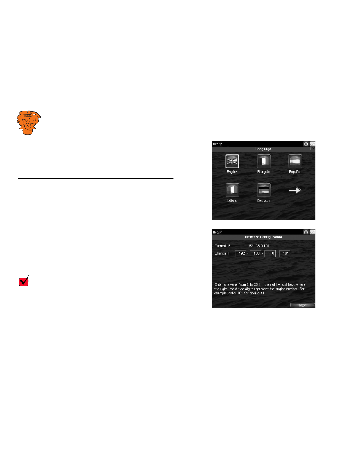
2. Select Installation Language
Select the language that should be used during the installation. There are 3 pages of
language options.
Note:
In this installation manual, all buttons and options are in English.
3. Select IP number
Enter an IP address. The IP address in the factory settings is 192.168.0.101.
The last 2 numbers in the main display's IP address are displayed as the engine number in the auxiliary display. Example:
• 192.168.0.101 is displayed in the auxiliary display as Engine #1.
• 192.168.0.104 is displayed in the auxiliary display as Engine #4.
The main display IP address can be changed at a later stage. This is done via Short-
cuts > Menu > Settings > Administration > Network Configuration in the main display.
REQUIREMENT!
The last numeral in the IP address must always be unique to the network.
372 513
372 514
Page 29
INSTALLATION
MANUAL
© Scania CV AB 2016, Sweden
Using the main display
03:03 Issue 5.0 en-GB 29
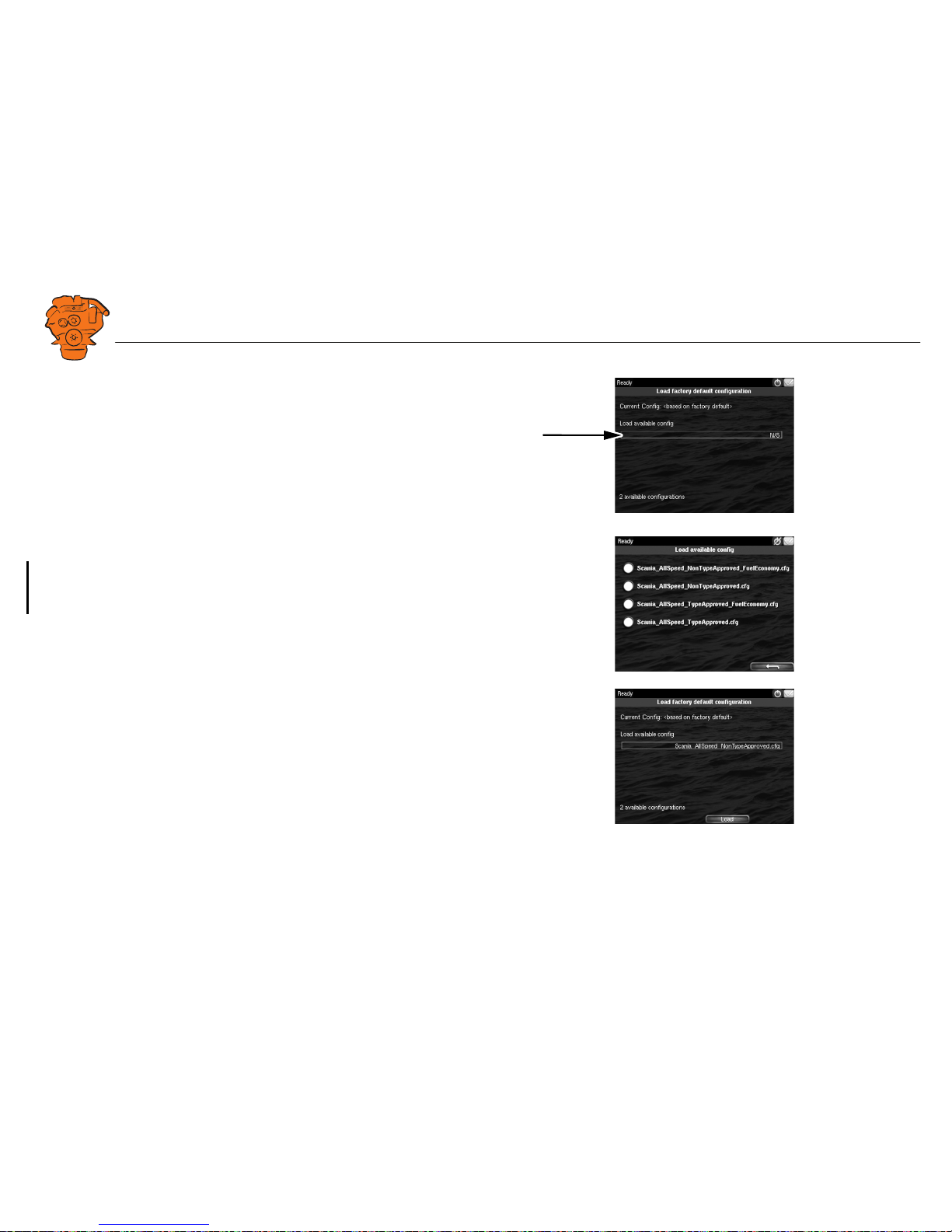
4. Load a configuration
Load a configuration file depending on whether the system is prepared for classification or not.
1. Press the bar. See illustration.
2. Select one of the available configuration files:
– Non-classified system with gateway for calculation of fuel consumption.
– Non-classified system.
– Classified system with gateway for calculation of fuel consumption.
– Classified system.
3. Press the arrow button.
5. Finish – Restart
Exit the first power-on wizard by pressing Load and then Restart.
372 515
372 516
372 517
Page 30

INSTALLATION
MANUAL
© Scania CV AB 2016, Sweden
Using the main display
03:03 Issue 5.0 en-GB 30
Navigation
Both the main display and auxiliary display are touch screens, without any buttons.
All functions are accessed by pressing the display.
The displays have 5 different display modes:
• Instrument pages
• Select Page
• Shortcut Menu
• Alarm List
• Menu
Different touch areas on the display have different functions. For example, if you
touch the left-hand side of the display on an instrument page, you get to the previous
instrument page. How to navigate:
To get to Press
Select Page in the middle of the display
previous instrument page on the left of the display
next instrument page on the right of the display
Shortcut Menu in the top left-hand corner
Alarm List in the top right-hand corner
Menu a long press (1 s) in the middle of the
display
Page 31

INSTALLATION
MANUAL
© Scania CV AB 2016, Sweden
Using the main display
03:03 Issue 5.0 en-GB 31
Instrument pages
The instrument page is the highest level in the main display structure. There are 4
preset instrument pages. It is also possible to configure a further instrument page so
that there will be 5 instrument pages in total.
• You scroll between the instrument pages by pressing on the right- or left-hand
side of the display.
Select Page
In Select Page thumbnails of the instrument pages and the Shortcuts menu are shown.
• You get to Select Page by pressing in the middle of the display.
• Then select one of the instrument pages from the thumbnails by pressing it.
372 518
Example of instrument page.
372 519
Page 32

INSTALLATION
MANUAL
© Scania CV AB 2016, Sweden
Using the main display
03:03 Issue 5.0 en-GB 32
Shortcut Menu
In the Shortcut Menu, buttons Start Engine, Stop Engine, Alarm List and Menu are
available. If the display has software version 2.12, there are also the Ignition Off and
Black Panel Mode buttons.
• Access the Shortcut Menu by pressing the upper left-hand corner of the display,
or by pressing Shortcuts in Select Page.
Alarm List
The Alarm List is described in the Operator's manual.
Menu
Only the administration section under Menu > Settings is described in this manual.
Other sections in the Menu are described in the Operator's manual.
Note:
You can switch off the button beep by going to Menu > Settings and selecting Disabled with the Button Beep button.
372 520
Page 33

INSTALLATION
MANUAL
© Scania CV AB 2016, Sweden
Using the main display
03:03 Issue 5.0 en-GB 33
Administration in the main display
Some settings can be made via the main display administration section. How to open
the administration section:
•Go to Select Page > Shortcuts > Menu > Settings.
• Scroll to page 3 in Settings and press Administration.
• The administration section is password-protected. Enter the password, which is
set at the factory to 1234.
The administration section consists of three pages and contains the buttons below.
The buttons are described in the following section.
372 521
Administration in the main display: pages 1, 2 and 3
Page 34

INSTALLATION
MANUAL
© Scania CV AB 2016, Sweden
Using the main display
03:03 Issue 5.0 en-GB 34
Password Configuration
This is where you can change the password for access to the administration section.
First, you have to enter the existing password.
Configuration Files
This is where you can restore the display to factory settings, load user-configured
files or delete user-configured files.
RIO 425
Not used.
SDU 410/SDU 404
This is where you synchronise the main display to the safety device unit and vice versa, if the system has a safety device unit.
372 522
372 540
Page 35

INSTALLATION
MANUAL
© Scania CV AB 2016, Sweden
Using the main display
03:03 Issue 5.0 en-GB 35
Network Configuration
This is where you change the IP address of the main display.
Note:
The last numeral in the IP address becomes the engine number in the auxiliary display.
System Type
This is where control panel settings are made:
Note:
The default setting is System Without Keyset. If the system has a control panel, you
must change the default setting.
Setting Description
System Without Keyset System without control panel
System With Keyset at This Station Control panel connected to this display
System With Keyset at Another Station Control panel connected to another dis-
play
372 056
372 057
Page 36

INSTALLATION
MANUAL
© Scania CV AB 2016, Sweden
Using the main display
03:03 Issue 5.0 en-GB 36
Adjust Idle Speed
Adjusting low idling. The following conditions must be met in order to adjust low
idling:
• The accelerator control should be at 0% and the engine should be idling.
• The engine coolant temperature should be at least 50°C.
Service Mode
If you activate Service Mode, the system is kept active, so that work on the engine
control unit, for example, can be carried out. The screensaver timer configured in the
Goto Sleep Time setting is bypassed. See Important system settings: dcu / Miscella-
neous / System Type. The button is only available if the display has software version
2.12.
Automatic Buzzer Silence
Activating and deactivating the automatic buzzer switch-off.
CANbus Amber Lamp
Set how Amber Lamp signals that are sent from the engine control unit to the main
display should be handled. Select if a warning (yellow alarm) should be displayed in
the main display or whether the signal should be deactivated.
CANbus Red Lamp
Set how Red Lamp signals that are sent from the engine control unit to the main display should be handled. You can select from the following options:
Disabled Red alarm via CAN bus deactivated
Alarm Red alarm via CAN bus activated
Shutdown Red alarm via CAN bus results in engine shutdown
372 523
Adjust Idle Speed.
372 524
Options for CANbus Red Lamp.
Page 37

INSTALLATION
MANUAL
© Scania CV AB 2016, Sweden
Configuring and upgrading software with USB memory stick
03:03 Issue 5.0 en-GB 37
Lock
Once the administrator password has been entered, the administration section is unlocked for 1 hour. Press Lock to lock the administration section immediately.
Factory Reset
This is where you reset the main display to factory settings.
Configuring and upgrading software with
USB memory stick
The USB inputs on the main display and auxiliary display can be used to
• configure the main display,
• upgrade the main display software or an auxiliary display,
• copy an existing configuration file in the main display in order to save a backup
copy of the configuration file or transfer the configuration to another display, for
example.
Note:
Files to be copied to a display must be saved in the root of the USB memory stick.
Valid characters in the configuration file name are a-z, A-Z, 0-9, _ (underscore) and
- (hyphen). If other characters are used, there is a risk that the display may not be able
to interpret them.
Page 38

INSTALLATION
MANUAL
© Scania CV AB 2016, Sweden
Configuring and upgrading software with USB memory stick
03:03 Issue 5.0 en-GB 38
Configuring the main display with a USB memory
stick
1. Insert the USB memory stick with the configuration files into the display.
2. Enter the administrator password (4 digits).
3. The window USB Storage is opened. Press Configuration Files.
4. The configuration files available on the USB memory stick are listed in the dis-
play.
5. Select the file or files you want to copy to the display and press Copy.
6. Confirm by pressing Yes. The files are not activated, they are only copied to the
display.
7. Select the configuration file you want to use and press Use.
8. Confirm by pressing Yes. The main display will restart.
Different configuration files in the same main display
It is possible to use different configuration files in the same main display. Do this by
first copying the configuration files from the USB memory stick according to the instructions above. Then go to Menu > Settings > Administration > Configuration Files
> Load User File to activate the file you want to use.
372 525
Page 39

INSTALLATION
MANUAL
© Scania CV AB 2016, Sweden
Configuring and upgrading software with USB memory stick
03:03 Issue 5.0 en-GB 39
Upgrading the main display or auxiliary display software
Note:
If the display is new or has factory settings restored, you must first go through the
first power-on wizard before you can upgrade the software.
1. Insert the USB memory stick with the new software version into the display.
2. Enter the administrator password (4 digits).
3. Press DCU Firmware Files and follow the instructions on the display.
Note:
When the software has been upgraded, the display will restart. This may take a few
minutes. Do not turn off the power until you have waited for at least 5 minutes for
the display to restart automatically.
Copying one configuration file in the main display
1. Insert the USB memory stick into the display.
2. Enter the administrator password (4 digits).
3. The window USB Storage is opened. Press Copy Configuration File and confirm
by pressing Yes.
The configuration file is now copied to the USB memory stick.
372 525
Page 40

INSTALLATION
MANUAL
© Scania CV AB 2016, Sweden
Configuring the main display via a web browser
03:03 Issue 5.0 en-GB 40
Configuring the main display via a web
browser
The main part of this section describes how to configure the main display via a web
browser. In the final subsection - SDU - some settings of the safety device unit are
also described, if the system has one.
The main display is configured using a computer with a web browser via the built in
web server of the main display. Therefore, connect a computer to the main display
first.
Connecting a computer to the main display
1. In the main display: Go to Shortcuts > Menu > Help > Version Information. Make
a note of the IP address. The IP address in the factory settings is 192.168.0.101.
2. Go to Shortcuts > Menu > Settings > Connect a PC.
372 526
372 527
Page 41

INSTALLATION
MANUAL
© Scania CV AB 2016, Sweden
Configuring the main display via a web browser
03:03 Issue 5.0 en-GB 41
3. Tick the Enabled box and press Ok.
4. Connect an Ethernet cable between the computer and the main display.
5. Enter the IP address in the address field of the web browser; for example: http://
192.168.0.101, and press Enter.
Approved web browsers:
Other web browsers probably also work but have not been tested.
Web browser Version
Internet Explorer
TM
9 or later
Firefox
TM
8 or later
Chrome
TM
10 or later
372 528
Page 42

INSTALLATION
MANUAL
© Scania CV AB 2016, Sweden
Configuring the main display via a web browser
03:03 Issue 5.0 en-GB 42
General information about the IP address
The main display has a fixed IP address, which is set in the first power-on wizard.
However, the IP address can always be changed later in the main display administration section:
• In the main display, go to Shortcuts > Menu > Settings > Administration > Net-
work Configuration.
Composition of the IP address
Within a network, the first 3 groups of the IP address must always be the same, Example:
192.168.0.X
where X represents another component on the network.
Note:
The last numeral in the IP address must always be unique to the network.
Factory settings for the main display
The factory settings only apply when the main display is started for the first time.
When the settings have been changed, the changes are saved even if factory settings
are restored.
• IP-adress: 192.168.0.101
• Subnet Mask: 255.255.255.0
• Default gateway: 192.168.0.1
Page 43

INSTALLATION
MANUAL
© Scania CV AB 2016, Sweden
Configuring the main display via a web browser
03:03 Issue 5.0 en-GB 43
Homepage
When you have connected a computer to the main display and entered the IP address,
the homepage is displayed. All configurations can be carried out via the built in web
interface.
The following menu options are available on the homepage:
Menu option Description
DCU To configure the main display. This menu option is described
in the following section.
RIO Not used.
SDU Safety device unit. This contains information about the safety
device unit, some settings can be also be made here. However,
as a general rule, no safety device unit settings may be
changed. If the settings are changed, the classification may no
longer be valid.
Upload Wallpaper Upload your own background images to the main display here.
The file format must be .png.
Versions Information on the hardware and software version of the main
display.
Troubleshooting Troubleshooting I/O communication in the main display.
344 457
Page 44

INSTALLATION
MANUAL
© Scania CV AB 2016, Sweden
Configuring the main display via a web browser
03:03 Issue 5.0 en-GB 44
Logging in to the main display
On the homepage: Click DCU and then log in to the main display with the following
details:
• User Name: dcu
• Password: 1234
The different configuration menus under Home > DCU are described in the following
section. The layout of this chapter reflects the menu structure of the web service interface, so that each menu in the illustration on the right has a section of its own. The
settings are saved to the main display and not to the computer.
Important system settings: dcu / Miscellaneous /
System Type
Some important settings regarding system type, screensaver and password are made
in the first step of the configuration. You do not have to change the factory settings,
but you should be aware of them.
Setting Description
System Type Select System Without Keyset for systems without a con-
trol panel.
Select System With Keyset at This Station if there is a control panel connected to this display.
Select System With Keyset at Another Station if a control
panel is connected to another display.
Goto Sleep Time [sec] Set the timeout for shutting down the system when no
control panel is being used (instead of starter key). The
setting applies when the system is in Ready mode, i.e.
once the engine has stopped. The standard setting is
1,000 seconds.
372 774
Page 45

INSTALLATION
MANUAL
© Scania CV AB 2016, Sweden
Configuring the main display via a web browser
03:03 Issue 5.0 en-GB 45
Password: dcu > Password
The configuration of the main display is password-protected. This is where you
change the password for the configuration.
If you have forgotten your password: Click Get encrypted PIN. An encrypted password is sent to you. The encrypted password can be decoded. Contact the Scania
helpdesk for more information.
Pin Code Change the system operator password if no control panel
is being used. The default setting is 0000.
Pin Code On Wakeup Specify whether an operator password should be used
(instead of starter key) if no control panel is being used.
Setting Description
Page 46

INSTALLATION
MANUAL
© Scania CV AB 2016, Sweden
Configuring the main display via a web browser
03:03 Issue 5.0 en-GB 46
File management: dcu > File
This menu is used for file management.
Submenu Description
Load any file Change the configuration of the main display by activat-
ing another configuration file.
Factory Default: Activate a factory-configured file.
User Uploaded: Activate a user-configured file which
has previously been uploaded to the main display via File
> Upload to DCU > Configuration. See Upload to DCU
below. When you activate the new configuration file, the
main display will restart.
Delete configuration file Remove the user-configured files.
Configuration printout Take a screenshot.
Save file as... Save the current main display configuration as a file on
the computer. The file is saved in .cfg format.
Upload to DCU Firmware: Upgrade the software in the main display to
the latest version.
Wallpaper: Upload your own background images to the
main display. The file format must be .png.
Configuration: Upload a new configuration file to the
main display. Note: The file will be uploaded but not activated. See Load any file above.
372 775
Page 47

INSTALLATION
MANUAL
© Scania CV AB 2016, Sweden
Configuring the main display via a web browser
03:03 Issue 5.0 en-GB 47
Configuring input signals: dcu > I/O Configuration >
Config Inputs
This is where you configure input signals to the main display.
Enter your own name for all input signals by clicking the assign custom name link,
at the top of every section.
Note:
Remember to click Submit after every change, otherwise they will not be saved.
Engine Speed
This is where the engine speed sensors are configured and the engine overspeed limit
value is set.
Source
The main display can receive signals for engine speeds from 3 different sources RPM Primary Source, RPM Secondary Source and RPM Third Source.
The engine speed sources have an order of priority. The main display uses the primary source in the first instance. The secondary source is only used if the main display
loses contact with the primary source.
Source Description
J1939 J1939 CAN bus connected to inputs 25-27.
DCU Magnetic detection locally connected to inputs 37 and 38.
SDU Signal from the safety device unit, if the system has one.
372 776
Page 48

INSTALLATION
MANUAL
© Scania CV AB 2016, Sweden
Configuring the main display via a web browser
03:03 Issue 5.0 en-GB 48
Local Pickup
Enter the number of pulses per engine revolution if a magnetic pulse sensor is connected to the main display, or if DCU has been selected from the sources above.
General Configuration
Setting Description
RPM Rounding Rounds off the value displayed in the display to 1, 5 or 10
rpm.
RPM Setpoint States the engine speed at which the starter motor is
switched off and the main display indicates that the engine is running.
RPM Setpoint 2–5 Optional engine speed settings which can be used togeth-
er with other sensors.
RPM Ready To Take
Load
A signal that can be configured to an output. The signal
is activated when the set engine speed is reached. The
signal is deactivated when a stop signal is sent, or when
the engine speed drops by 15% or more below the set value.
RPM Nominal Speed Nominal engine speed. This engine speed is used to cal-
culate the engine overspeed limit value and the engine
overspeed test limit value.
372 776
Page 49

INSTALLATION
MANUAL
© Scania CV AB 2016, Sweden
Configuring the main display via a web browser
03:03 Issue 5.0 en-GB 49
General > Channel Use
Select the display in which the signal should be displayed graphically. This display
is possible on the main display (DCU), auxiliary display (RP) or on both simultaneously (DCU+RP).
Display
Set the way in which the signal will be displayed on the tachometer.
Setting Description
Display Range Min The lowest engine speed displayed on the tachometer,
normally 0.
Display Range Max The highest engine speed displayed on the tachometer.
For an engine with a nominal engine speed of 1,500 rpm,
the maximum engine speed may be 1,800 rpm, for example.
Display Major Divider The larger scale marks on the tachometer, i.e. how often
the tachometer records an rpm value. A common setting
is every 500 rpm.
Display Minor Divider The minor scale marks between the larger scale marks
(Major Divider) on the tachometer. A common setting is
every 100 rpm.
Display Multiplier The multiplication factor displayed on the tachometer,
e.g. x100 rpm.
372 776
Page 50

INSTALLATION
MANUAL
© Scania CV AB 2016, Sweden
Configuring the main display via a web browser
03:03 Issue 5.0 en-GB 50
Overspeed
Individual Speed Sensors
Set the inputs for optional engine speed signals in Individual Speed Sensors. Signals
coming in via these inputs are handled separately from the engine speed signals that
were configured in the previous section.
Engine speed (DCU)
Setting Description
RPM Overspeed The value at which the main display will indicate engine
overspeed.
RPM Overspeed Delay Delay in milliseconds before an alarm or engine shut-
down occurs, normally 100 ms.
RPM Overspeed Shutdown Enabled
How the engine should react to engine overspeed. Select
Yes if the engine should be shut down at engine overspeed, or No if the engine should not be shut down at engine overspeed.
Setting Description
Channel Use Select the display in which the signal should be displayed
on the tachometer. Display is possible on the main display, on the auxiliary display or on both simultaneously.
Sensor Unit Only RPM can be selected here.
Sensor Range Min/ These are fixed values that cannot be changed.
Sensor Range Max
Display Unit Only RPM can be selected.
Display Range Min Select the lower part of the scale.
Display Range Max Select the upper part of the scale.
Display Major Divider Select the larger scale marks, where the rpm value is also
shown.
Page 51

INSTALLATION
MANUAL
© Scania CV AB 2016, Sweden
Configuring the main display via a web browser
03:03 Issue 5.0 en-GB 51
Engine Speed (J1939)/Engine Speed (SDU)
See previous section.
Engine Load
Select an engine load source in the Engine Load Source drop-down list. You can now
select engine load as a setting when configuring the alarm.
Transmission
This menu is used to display the gear engaged or to inhibit engine start if a gear is
engaged.
Display Minor Divider Select the number of scale marks that should be displayed
between the larger scale marks (Major Divider).
Display Multiplier Select the multiplication factor to be displayed on the dis-
play: 1, 10, 100 or 1,000.
Event Determine how the engine should react to different
events for this input.
Setting Description
Page 52

INSTALLATION
MANUAL
© Scania CV AB 2016, Sweden
Configuring the main display via a web browser
03:03 Issue 5.0 en-GB 52
Switch
In systems with a control panel, the main display has five configurable inputs. If there
is no control panel and the software version of the display is 2.12, the five inputs 4448 are also configurable.
The inputs can be configured so that they are compatible with a regular switch or sensor. They can also be configured to perform a function, e.g. automatic starting. The
inputs are activated by applying 24 V to each input.
Note:
Inputs 1-3 (39-41) are reserved in systems with a safety device unit.
Select one of the inputs and configure it according to the instructions below.
Use as
Set the input function. The functions written in bold are the most common. Some of
the functions are only available if the software version of the display is 2.12.
Setting Description
None The input is used as an input for a regular engine sen-
sor.
Local Mode Sets the display into local mode, i.e. all external com-
mands are blocked.
Remote Mode External commands are accepted.
0V
12 / 24V
USB Memory
Pow
er
Inputs
Pow
er Supply
Eth
Out 1
Out 3
Out 4
Out 5
Out 6
Out 2
Outputs
24V 0.2A
4
In 5
In 1
In 2
In 3
In 4
Key set
123456789
10
48 47 46 45 44 43 42 41 40 39
372 778
Page 53

INSTALLATION
MANUAL
© Scania CV AB 2016, Sweden
Configuring the main display via a web browser
03:03 Issue 5.0 en-GB 53
Setting Description
Backlight 100 Percent Forces the background lighting to light at 100 per cent.
Prelube Override Not used.
Prelube Complete Not used.
Start Disabled Engine start deactivated.
Automatic Mode The display accepts automatic start and stop signals.
Automatic Start The display initiates the start sequence. Automatic
Mode must be activated.
Automatic Stop The display initiates the shutdown sequence. Automat-
ic Mode must be activated.
Remote Start Same as starter button. The display must be in Remote
mode.
Remote Stop Same as stop button. The display must be in Remote
mode.
Local Start Same as starter button. The display must be in Local
mode.
Local Stop Same as stop button. The display must be in Local
mode.
0V
12 / 24V
USB Memory
Pow
er
Inputs
Pow
er Supply
Eth
Out 1
Out 3
Out 4
Out 5
Out 6
Out 2
Outputs
24V 0.2A
4
In 5
In 1
In 2
In 3
In 4
Key set
123456789
10
48 47 46 45 44 43 42 41 40 39
372 778
Page 54

INSTALLATION
MANUAL
© Scania CV AB 2016, Sweden
Configuring the main display via a web browser
03:03 Issue 5.0 en-GB 54
Setting Description
Local Acknowledge Acknowledge all events in the alarm list. The display
must be in Local mode.
Local/Remote Acknowledge
Acknowledge all events in the alarm list.
Remote Acknowledge Acknowledge all events in the alarm list. The display
must be in Remote mode.
Shutdown Override Allows all configured engine shutdown inputs to be-
come alarm inputs. The engine is then not shut down
automatically. Engine shutdown during engine overspeed is however always active.
In Gear Signal from the gearbox that engine start is not possible
due to a gear being engaged. Applies only if the engine
drives a propeller. The function can only be configured
as Normally open or Normally closed if the software
version of the display is 2.12.
0V
12 / 24V
USB Memory
Pow
er
Inputs
Pow
er Supply
Eth
Out 1
Out 3
Out 4
Out 5
Out 6
Out 2
Outputs
24V 0.2A
4
In 5
In 1
In 2
In 3
In 4
Key set
123456789
10
48 47 46 45 44 43 42 41 40 39
372 778
Page 55

INSTALLATION
MANUAL
© Scania CV AB 2016, Sweden
Configuring the main display via a web browser
03:03 Issue 5.0 en-GB 55
Setting Description
In Gear (Ahead) Signal from the gearbox that engine start is not possible
due to a forward gear being engaged. Applies only if
the engine drives a propeller.
In Gear (Astern) Signal from the gearbox that engine start is not possible
due to reverse gear being engaged. Applies only if the
engine drives a propeller.
Toggle Crank Mode Switch between running the engine normally and with
the starter motor only.
Torque Limitation Curve
1-3
Activate torque limitation curve 1-3.
Speed Mode 1-2 Activate engine speed setting 1-2.
Speed Mode Off Deactivate engine speed setting.
Ignition Voltage on.
Start Start the engine.
0V
12 / 24V
USB Memory
Pow
er
Inputs
Pow
er Supply
Eth
Out 1
Out 3
Out 4
Out 5
Out 6
Out 2
Outputs
24V 0.2A
4
In 5
In 1
In 2
In 3
In 4
Key set
123456789
10
48 47 46 45 44 43 42 41 40 39
372 778
Page 56

INSTALLATION
MANUAL
© Scania CV AB 2016, Sweden
Configuring the main display via a web browser
03:03 Issue 5.0 en-GB 56
Channel Use
Set the input should be used.
Event = Warning, alarm or, torque limitation or engine shutdown.
Note:
Select normally DCU+RP+Event. Then the signal is displayed on both the main display and the auxiliary display. If the signal only needs to be displayed on the main
display, select DCU+Event.
Setting Description
Not in use The input must not be used.
Event The signal will activate an event.
DCU The signal will only be displayed in the main display.
DCU+Event The signal will activate an event that is only displayed
in the main display.
RP The signal will only be displayed in the auxiliary dis-
play.
RP+Event The signal will activate an event that is only displayed
in the auxiliary display.
DCU+RP The signal will be displayed in both the main display
and auxiliary display.
DCU+RP+Event The signal will activate an event which is displayed in
both the main display and auxiliary display.
Silent Event The input will be active, but the signal will not trigger
any event which is displayed in the display. The signal
is only used for communication.
0V
12 / 24V
USB Memory
Pow
er
Inputs
Pow
er Supply
Eth
Out 1
Out 3
Out 4
Out 5
Out 6
Out 2
Outputs
24V 0.2A
4
In 5
In 1
In 2
In 3
In 4
Key set
123456789
10
48 47 46 45 44 43 42 41 40 39
372 778
Page 57

INSTALLATION
MANUAL
© Scania CV AB 2016, Sweden
Configuring the main display via a web browser
03:03 Issue 5.0 en-GB 57
Event
If you have chosen a type of event (Event or Silent Event) under Channel Use, you
should select the type of event here, i.e. warning, alarm or engine shutdown.
If None is selected then the input is active but no events are triggered.
Input State
Delay Before Event
If you have selected an event under Event, here you enter the desired delay in seconds
before the event is triggered.
Delayed Shutdown
If you have selected engine shutdown under Event, here you enter the desired delay
in seconds before engine shutdown.
Requires Running Engine
Normally, select Yes for a pressure sensor and No for all other sensors. Select a different value in order to activate the input at another engine speed.
Setting Description
Normally Closed, Event
on open
The switch must be open in order for an event to be
triggered.
Normally Open, Event on
Closed
The switch must be closed in order for an event to be
triggered.
0V
12 / 24V
USB Memory
Pow
er
Inputs
Pow
er Supply
Eth
Out 1
Out 3
Out 4
Out 5
Out 6
Out 2
Outputs
24V 0.2A
4
In 5
In 1
In 2
In 3
In 4
Key set
123456789
10
48 47 46 45 44 43 42 41 40 39
372 778
Page 58

INSTALLATION
MANUAL
© Scania CV AB 2016, Sweden
Configuring the main display via a web browser
03:03 Issue 5.0 en-GB 58
Requires In Gear
Select Yes if an engaged gear is required for an event to be triggered.
Requires Engine Load
Select Yes if engine load is required for an event to be triggered.
Initial Delay
Set the delay in seconds before which the input should be activated. This setting can
only be made if Requires Running Engine is activated.
Use As Additional Run
If the main display only has one engine running indicator, Scania recommends adding the oil pressure sensor as an additional engine running indicator.
IMPORTANT!
Use no other pressure sensor signals or other signals as engine running indicator.
• If the main display has two active engine running indicators
1
: Select No.
• If the main display only has one active engine running indicator: Select Yes and
use the oil pressure sensor as a further engine running indicator.
1. An engine running signal can be a magnetic sensor or an SAE J1939 CAN bus signal connected to
the main display.
0V
12 / 24V
USB Memory
Pow
er
Inputs
Pow
er Supply
Eth
Out 1
Out 3
Out 4
Out 5
Out 6
Out 2
Outputs
24V 0.2A
4
In 5
In 1
In 2
In 3
In 4
Key set
123456789
10
48 47 46 45 44 43 42 41 40 39
372 778
Page 59

INSTALLATION
MANUAL
© Scania CV AB 2016, Sweden
Configuring the main display via a web browser
03:03 Issue 5.0 en-GB 59
4-20 mA
First select one of the 4-20 mA inputs. Then configure the input according to the instructions below.
Channel Use
See Channel Use
in the Switch section.
Sensor
Display
Setting Description
Sensor Unit Select the unit indicated on the sensor. An oil pressure
sensor can, for example, have bar or psi as units.
Sensor Range Min/Sensor Range Max
Select the sensor measuring range, i.e. the highest and
lowest values recorded by the sensor.
Setting Description
Display Unit Select the unit in US and Metric to be shown in the sensor
display.
Display Range Min/Display Range Max
Select the highest and lowest value in US and Metric that
should be displayed on the display for the sensor.
Display Major Divider/
Display Minor Divider
Select the desired minor and larger scale marks in US and
Metric that should be displayed on the display for the sen-
sor.
Display Multiplier If necessary, select a multiplication factor. For an instru-
ment with a display range of 0-10,000, e.g. 0-1,000 is displayed with a multiplication factor of 10. The
multiplication factor of 10 will then be shown separately
on the display (only applies to round dial meters).
0V
12 / 24V
USB Memory
Power
Pow
er Supply
Ethernet
Out 1
Out 3
Out 4
Out 5
Out 6
Out 2
Outputs
24V 0.2A
Ch
.
1
Ch
.
2
4-20 mA
123456789
10 11 12
372 778
Page 60

INSTALLATION
MANUAL
© Scania CV AB 2016, Sweden
Configuring the main display via a web browser
03:03 Issue 5.0 en-GB 60
Alarming > Event
If you have chosen a type of event (Event or Silent Event) under Channel Use, you
should select the type of event here, i.e. warning, alarm or engine shutdown. Select
RPM dependent if the values should vary according to the engine speed.
PT100
Select one of the PT100 inputs. Then configure in the same way as under the 4-
20 mA heading on the previous pages.
Update Metric/Update USWhen you have entered all values under either US or Met-
ric, you can calculate the Metric- eller US values auto-
matically by clicking Update Metric or Update US.
Note: The values are not rounded. Scania therefore recommends adjusting the values manually afterwards, with
a suitable number of decimal places.
Setting Description
LHL
H
RIO / SDU
Link
RS-485
Modb
us
A
B
C
1
PT100
2
A
B
C
13 14 15 16 17 18 19 20 21 22 23 24
372 780
Page 61

INSTALLATION
MANUAL
© Scania CV AB 2016, Sweden
Configuring the main display via a web browser
03:03 Issue 5.0 en-GB 61
J1939
Find the desired signal in one of the following ways:
• Select the first letter of the signal in the column on the left-hand side. Example:
If you are looking for the Fuel rate signal, select D-F in the left-hand column.
Then find the signal in the displayed list.
• Search for the signal by inputting information in one of the fields under J1939 sig-
nal search and then click Search.
• Click All in the left-hand column and find the signal in the displayed list.
Configure the signal in the same way as under the heading 4-20 mA
on previous pag-
es.
Differential
A differential input is a logical input consisting of 2 physical inputs. The physical inputs can be connected from the J1939 CAN bus. The value of the differential input
is made up by the difference between the values of the 2 physical inputs.
Both of the physical inputs must have the same type of sensor. Example: both sensors
must send a value in bar. The differential signal can be displayed graphically in the
display.
344 463
344 464
Page 62

INSTALLATION
MANUAL
© Scania CV AB 2016, Sweden
Configuring the main display via a web browser
03:03 Issue 5.0 en-GB 62
Special
These are signals which cannot be linked to any other group in a natural manner.
Submenu Description
Input Voltage The incoming voltage is monitored with fixed limit val-
ues according to the following:
Warning: < 21 V
Alarm: < 18 V
You can add more limit values for warnings and alarms
here. It is also possible to set how the voltage should be
displayed graphically on the display.
Calc. Fuel Rate The main display can calculate the fuel consumption and
show an approximate value. Select an input and then configure in the same way as under the 4-20 mA heading.
Engine Hours If the engine's hour counter is not available on the J1939
CAN bus, it can be calculated by the main display. This
is where you configure how the hour counter should be
displayed in the display. The basis for the calculation is
inputted via Home > DCU > Miscellaneous > Fuel Con-
sumption.
Instantaneous Fuel
Economy (DCU)
The main display can calculate the current fuel consumption using the values for calculated or measured fuel consumption and vehicle speed.
372 782
372 783
Page 63

INSTALLATION
MANUAL
© Scania CV AB 2016, Sweden
Configuring the main display via a web browser
03:03 Issue 5.0 en-GB 63
Configure output signals: dcu > I/O Configuration /
Config Outputs
The output signals from the main display are configured from here. Enter your own
name for all output signals by clicking assign custom name, at the top of every section.
Note:
Remember to click Submit after every change, otherwise they will not be saved.
The available functions for the outputs are listed in the table. The functions written
in bold are the most common.
In addition to the fixed functions described in the table, the following functions are
also in the list:
• Configured SAE J1939 signals.
• All configured events, e.g. a sensor that has been configured to generate a warning, alarm or engine shutdown.
Function Description
Acknowledge Button The acknowledgement button is activated
Buzzer Active The buzzer is activated
Shutdown in Alarm List There is an event in the alarm list which has caused an engine shutdown
Alarm in Alarm List There is an event in the alarm list which has caused an alarm
Warning in Alarm List There is an event in the alarm list which has caused a warning
All Faults (Unacknowledged) There is a new event in the alarm list
Common DM1 in Alarm List There is a diagnostic message from the engine control unit in the alarm list
Ready State The main display is ready
Init. Delay State The time which should pass between the sending of an automatic start signal and the first start attempt
Page 64

INSTALLATION
MANUAL
© Scania CV AB 2016, Sweden
Configuring the main display via a web browser
03:03 Issue 5.0 en-GB 64
Cranking State The main display activates the starter motor
Awaiting Run State The starter motor has been switched off and the main display is waiting for the engine to rev up
Running State The engine is running
Crank Delay State The time which should pass between automatic start attempts with the starter motor
Delayed Stopped State Status is active and the timer is counting down
Cooling State The display has activated alternator shutdown and the engine is idling
Stopping State The engine shuts down
Stopped State The engine has shut down (engine speed is under 5 rpm) and this status has been active for at least 10 seconds
Blocked State The engine cannot be started, usually because there is an engine shutdown event which has not been acknowledged
Stopped For Unknown Reason The display is not receiving signals indicating that the engine is running, but no shutdown command has been sent to the main display. Run
out of fuel?
First Start Attempt Failed The first in a series of automatic start attempts has failed
Final Start Attempt Failed In a series of automatic start attempts, the last attempt has failed, including the starter motor rest periods between start attempts
In Local Mode The display is in local mode, i.e. all external commands are blocked.
DCU Tacho Failure Sensor signal lost during operation
Service Interval A configured maintenance interval has been reached
Engine Protection Override The display is in engine shutdown override mode, and engine shutdown signals are now sent as alarms only. Engine shutdown in the event
of engine overspeed is always active
Power on The display has power
Supply Voltage Low The voltage is under the limit value
Speed Switch 1-4 The function is activated at configured engine speeds.
Alarm or Ack Button or Remote
Acknowledge
An acknowledgement is carried out in the display and the buzzer is switched off
Common Start Failed A collective message indicating that the engine has not started
Common Stop Failed A collective message indicating that the engine has not stopped, e.g. the stop signal has been activated but the engine has not stopped within
the given stop time
Function Description
Page 65

INSTALLATION
MANUAL
© Scania CV AB 2016, Sweden
Configuring the main display via a web browser
03:03 Issue 5.0 en-GB 65
12/24V Output Functions
The main display has six 12/24 V outputs. Select one of the outputs, User Config
Output #1 to User Config Output #6 and set the function it should have by selecting
an option in the Event drop-down list. Refer to previous pages.
Soft Button 1, 2, 3, 4 One of the buttons on the bottom edge of the display is activated
Ready To Take Load The engine speed is above the set value for Ready to take load
Ready for PMS Start Active when the voltage is > 21 V and the display is in automatic mode
New Alarm Pulse When a new event appears in the alarm list, this function is activated for 1 second and is then deactivated automatically
In Manual Mode The display is in manual mode and cannot start automatically
Overspeed The engine speed is above the set value for engine overspeed
In Remote Mode The display can receive remote commands
ETR Activated when the engine is running or when it is started, deactivated by a stop command
ETS Activated when the engine receives a stop command and remains active for 10 seconds after the engine has stopped
Shutdown The engine is shut down automatically by a sensor signal, including engine overspeed
Running The engine is running
Crank The display sends a signal to the starter motor to start the engine
Prelube Activation The display has activated the prelube function
Emergency Start/Mode The display is in emergency mode, or an emergency start sequence has been activated
Function Description
0V
12 / 24V
Pow
er Supply
Out 1
Out 3
Out 4
Out 5
Out 6
Out 2
Outputs
123456789
372 785
Page 66

INSTALLATION
MANUAL
© Scania CV AB 2016, Sweden
Configuring the main display via a web browser
03:03 Issue 5.0 en-GB 66
Relay Functions
The main display has 2 integrated potential free relay inputs where a function can be
connected. Select 1 of the 2 relays and indicate which function it should have. Refer
to previous pages.
Speed Relays
A speed relay is a relay that is activated at a certain engine speed and is deactivated
below that engine speed. In the example below, Speed Relay #1 is configured so that
it is activated at an engine speed over 1,200 rpm and deactivated under 1,200 rpm.
An event is created in the alarm list when the speed relay is activated.
1. Activate the speed relay by selecting Yes for Speed Relay #1 Enabled.
2. Select 1,200 for Speed Relay #1 Activate Speed [RPM].
3. Select the type of event with Event.
4. Select Yes for Event Log. An event is now created in the alarm list when speed
relay 1 is activated.
5. Enter a delay in seconds before which the event should be triggered using Delay
After Crossing Threshold.
The selected speed relay can now be linked to any configurable output.
J1939 Outputs
Find the desired signal in one of the following ways:
• Select the first letter of the signal in the column on the left-hand side. Example:
If you are looking for the Fuel rate signal, select D-F in the left-hand column.
Then find the signal in the displayed list.
• Search for the signal by inputting information in one of the fields under J1939 sig-
nal search and then click Search.
• Click All in the left-hand column and find the signal in the displayed list.
• Configure the signal in the same way as under the 4-20 mA
heading.
H
L
CAN J1939
All Faults
NO
NC
Rela
y 1
NO
NC
Rela
y 2
NO
NC
1A
1A
1A
C
C
C
36 35 34 33 32 31 30 29 28 27 26 25
372 786
372 787
372 789
Page 67

INSTALLATION
MANUAL
© Scania CV AB 2016, Sweden
Configuring the main display via a web browser
03:03 Issue 5.0 en-GB 67
Designing instrument pages: dcu > Interface Design
Via Interface Design you can add the signals which were configured in I/O Configuration to the instrument pages.
Pages
The instrument pages are configured here. The main display can have a maximum of
5 different instrument pages.
This is how an instrument page is constructed:
• Each instrument page (Page) is based on a template (Template).
• A template has several different areas (Slots).
• Each Slot can contain one Widget. A Widget is a gauge needle or a bar, for example.
• Each Widget can be allocated one signal.
In the example in the illustration there are four instrument pages. Select one of the
instrument pages by clicking it.
344 468
Page 68

INSTALLATION
MANUAL
© Scania CV AB 2016, Sweden
Configuring the main display via a web browser
03:03 Issue 5.0 en-GB 68
In the example on the right, Page 1 has been selected. As you can see, this instrument
page is based on Template 14. There are 9 Slots with one Widget in each Slot. Slot 1,
2, 3, 6 and 7 are each assigned a signal.
Adding a signal to a Slot
•Under Populate Slots, select a signal by clicking the drop-down list for the desired
Slot. Only the signals configured for use are displayed in the drop-down list.
Changing a signal
• Click Edit Signal to the right of the desired Slot.
Adding a new instrument page
•Under Page Manipulation at the top of the window, select whether the new instru-
ment page should be displayed before or after one of the existing instrument pages. Then click Insert Page. The instrument pages are automatically renumbered.
• Select a template for the current instrument page by clicking one of the templates
displayed under Select Template. The Template currently selected for the instrument pages is displayed at the bottom of the window under Current template.
• Configure the instrument page according to the description above and click Sub-
mit when finished.
Deleting an instrument page
Select the instrument page you want to delete under Select Page and click Delete
Current Page at the bottom of the window. The instrument pages are automatically
renumbered.
Check that you are deleting the correct instrument page, as there is no Undo function.
346 785
Page 69

INSTALLATION
MANUAL
© Scania CV AB 2016, Sweden
Configuring the main display via a web browser
03:03 Issue 5.0 en-GB 69
Set the sequences for starting, stopping and for lubrication: dcu > Start/Stop/Prelube
Set manual and automatic engine start and shutdown sequences.
General/Prelube
The following general settings under General and Prelube cannot be changed:
Setting Description
Hold Button to Start/Stop Must be Yes.
Allow E-Start Must be No.
Prelube Type Must be No Prelube.
Oscillating Prelube Must be No.
372 791
Page 70

INSTALLATION
MANUAL
© Scania CV AB 2016, Sweden
Configuring the main display via a web browser
03:03 Issue 5.0 en-GB 70
Automatic Start/Starter
The main display can start the engine automatically. The following conditions must
then be met:
• An input must be configured as automatic start and activated.
• The main display must be in automatic mode in Menu > Settings > Operation
Mode.
Setting Description
Initial Start Delay [seconds]
When the start sequence is activated, this amount of
time must have passed before the main display performs the first attempt to start.
Normal setting: 1 second.
No. of Start Attempts The total number of start attempts.
Normal setting: 3 start attempts.
Prelube Before Each Start
Attempt
Not used, must be No.
Cranking Time [seconds] The time the starter motor should be activated.
Normal setting: 5-7 seconds.
Delay Between Start Attempts [seconds]
If the engine did not start during a previous start attempt, this setting dictates the time until the next start
attempt.
Normal setting: 5-7 seconds.
372 791
Page 71

INSTALLATION
MANUAL
© Scania CV AB 2016, Sweden
Configuring the main display via a web browser
03:03 Issue 5.0 en-GB 71
Automatic Stop/Stopping
The main display can shut down the engine automatically. The following conditions
must then be met:
• An input must be configured as automatic stop and activated.
• The main display must be in automatic mode in Menu > Settings > Operation
Mode.
Setting Description
Delay Before Disconnecting Generator Breaker
[seconds]
When automatic stop is activated, the main display
waits for the number of seconds set here before sending
the signal indicating that the alternator's battery master
switch is to be disconnected. The Disconnect Genera-
tor Breaker signal is not a standard output signal. It
must be configured to a 24 V output or a relay output.
Normal setting: 1-60 seconds.
Cooling Time [minutes] When a time setting has been exceeded, the engine
continues to run without load for the time set here.
Normal setting: 1-10 minutes.
Stopping Time [minutes] Maximum stop time before the engine control unit
sends an alarm that the engine has not shut down.
Normal setting: 30 s.
372 791
Page 72

INSTALLATION
MANUAL
© Scania CV AB 2016, Sweden
Configuring the main display via a web browser
03:03 Issue 5.0 en-GB 72
Settings for the user interface: dcu > User Interface
Language and buzzer settings are made here.
Language
This is where you translate signal descriptions manually to other languages. The
translated signal descriptions are then displayed in the displays.
All signals
By clicking All signals, all signals that are available in the main display are displayed. 3 text columns describing the signals are displayed. Example:
The columns contain the following descriptions:
• English Default: The text used if no change is made.
• English Used: The text which will actually be displayed on the display. If [de-
fault] is displayed, the description in English Default is used.
• Norwegian Used: The text displayed on the display when the operator has selected this language (in this case Norwegian).
Click the signal description you want to change.
English Default English Used Norwegian used
Engine Oil Press. Engine Oil Pressure Motoroljetrykk
Engine Speed [default] Motorturtall
Page 73

INSTALLATION
MANUAL
© Scania CV AB 2016, Sweden
Configuring the main display via a web browser
03:03 Issue 5.0 en-GB 73
Enabled Signals Only
This section works in the same way as All signals. The difference is that only the sig-
nals which are used are displayed.
Service
Not used.
Buzzer
Set how the buzzer should be used in the display.
Select Yes under Automatic Buzzer Off if you want the buzzer to be switched off automatically. The buzzer is then activated as previously, but the main display will automatically switch it off after 0.5 seconds.
The function is designed to be used during configuration, when accidental alarms
may occur. It is automatically deactivated after 1 hour.
Changing the engine designation: dcu > Engine
Model
Here you can change the name of the engine to a more suitable name, e.g. "Hjälpmotor" or "Vabis". The default name is "Engine".
The last 2 numbers in the main display's IP address show the engine number. Example: If the IP address is 192.168.0.110, then the engine in the previous example will
be called "Auxiliary #10" or "Vabis #10". The name of the engine is displayed in the
auxiliary display.
346 788
Page 74

INSTALLATION
MANUAL
© Scania CV AB 2016, Sweden
Configuring the main display via a web browser
03:03 Issue 5.0 en-GB 74
Setting the maintenance interval: dcu > Service Interval
Set a maintenance interval at the request of the customer. There are no default settings.
In the View Service Status submenu, the number of hours until the next maintenance
is displayed. All values displayed are operating hours for the engine.
You can set up to four different maintenance intervals in the Configure submenu.
You can change the text for Service x by clicking the assign custom name link.
Setting Description
Service Enabled Activate the maintenance interval with Yes.
Next Service At Enter a value for the first maintenance in the main display
hour counter. The setting only gives one maintenance notification for the first maintenance. This setting is useful
if the first maintenance is to take place within a shorter interval than the normal maintenance interval.
Then Every Enter a maintenance interval in hours. The main display
indicates whenever a maintenance interval is due to expire. Example: The main display has a timer setting of
140 h. The next maintenance is at 150 h. The next maintenance then occurs every 250 h. The first maintenance
reminder is displayed in the main display after 10 h. A reminder is then displayed every 250 h.
346 789
Page 75

INSTALLATION
MANUAL
© Scania CV AB 2016, Sweden
Configuring the main display via a web browser
03:03 Issue 5.0 en-GB 75
Network settings: dcu > Communication
Network Configuration
The IP address, netmask and gateway for the main display are entered here.
Check that the IP address is unique for the network. If the main display is to be installed in an existing network: Contact your network manager to receive an IP address.
Modbus RTU
The main display has a built-in Modbus RTU interface.
Modbus I/O list
The I/O list for communication is at this address: http://bit.ly/K41IbK
Modbus parameters
Transfer speed 19,200
Data bits 8
Stop bit 1
Parity Even
Setting Description
Address Modbus identity number for the RS-485 channel. The ID
number can be any integer between 1 and 247. It must
also be unique to the network.
372 792
Page 76

INSTALLATION
MANUAL
© Scania CV AB 2016, Sweden
Configuring the main display via a web browser
03:03 Issue 5.0 en-GB 76
J1939 Configuration
This is where you configure how the SAE J1939 CAN bus should work.
Submenu Description
Source address The preset source address for the display is 27 (Hex).
Allowed Addresses Filtering units on the CAN bus so that the main display
can read data from selected units. Normally, all sources
are accepted.
Allowed DM1 Addresses Filtering units on the CAN bus so that the main display
can read data from selected units. Normally, all sources
are accepted.
372 793
Page 77

INSTALLATION
MANUAL
© Scania CV AB 2016, Sweden
Configuring the main display via a web browser
03:03 Issue 5.0 en-GB 77
Other functions: dcu > Miscellaneous
This is where other functions are configured.
Alarm Configuration
This is where you configure how the SAE J1939 CAN bus should work in the event
of an alarm.
Setting Description
J1939 CANbus Broken Wire Alarm
When Engine Not Running
The setting should be No.
J1939 CANbus Red Lamp Severity Set how Red Lamp signals that are sent
from the engine control unit to the main
display should be handled. Select Disa-
bled if the main display should disregard
red alarms. Select Alarm if a red alarm
should be triggered or Shutdown for engine shutdown.
J1939 CANbus Amber Warning Lamp
Enabled
Set how Amber Lamp signals that are
sent from the engine control unit to the
main display should be handled. Select if
a warning (yellow alarm) should be displayed in the main display or whether the
signal should be deactivated.
RP Lost Warning Enabled Use this setting if a warning should be
displayed if communication with the
auxiliary display is broken.
372 794
Page 78

INSTALLATION
MANUAL
© Scania CV AB 2016, Sweden
Configuring the main display via a web browser
03:03 Issue 5.0 en-GB 78
Counters
No changes may be made. The source for calculating the engine operating time
should come from the J1939 CAN bus. All changes that are made under Update Lo-
cal Engine Hours will be overwritten by the J1939 CAN bus.
Fuel Consumption
This submenu is only available if the display has software version 2.11 or earlier.
The main display can calculate an approximate fuel consumption. For this to work,
you must fill in the calculation configuration with input data from the engine specification. You must also configure the signal in the Special menu under I/O Configu-
ration.
Acknowledge Configuration
If you activate the function by selecting Yes, all alarms are acknowledged at once
when the operator presses the acknowledge button for one second. The standard setting is No. If there are more alarms in the alarm list than those displayed in the dis-
play, the alarms which are not displayed are also acknowledged.
372 795
Page 79

INSTALLATION
MANUAL
© Scania CV AB 2016, Sweden
Configuring the main display via a web browser
03:03 Issue 5.0 en-GB 79
Event Log
The main display has a log where all events are saved. Set how the log should be displayed.
Suppress DM1 Faults
Enter the combinations of SPN and FMI messages which are not to be displayed on
the main display.
Engine Application Configuration
Set how the engine should be used. Depending on the settings made here, the operator can select from the display modes offered.
Setting Description
Everything A list of all events in chronological order.
Alarms Only A list of all warnings, alarms and engine shutdowns.
User Interaction Only A list of all buttons pressed on the display.
Commands Only A list of all executed remote commands on the main
display.
Events Only A list of all events that are not alarms, e.g. power on.
Sequence Only
Save as... Save the list displayed to the computer as a text file.
346 797
Page 80

INSTALLATION
MANUAL
© Scania CV AB 2016, Sweden
Configuring the main display via a web browser
03:03 Issue 5.0 en-GB 80
Shutdown Override Configuration
System Voltage
The system voltage must always be set to 24 V.
System Type
More information can be found under the heading Important system settings: dcu /
Miscellaneous / System Type.
Setting Description
SDU
Transmit Shutdown Override to SDU
Signal to the safety device unit to override engine shutdown.
J1939
Transmit Shutdown Override [SPN 1237]
Signal to override engine shutdown to engine control
unit via the CAN bus.
Shutdown Override from
J1939
Signal to override engine shutdown from engine control unit via the CAN bus.
372 796
Page 81

INSTALLATION
MANUAL
© Scania CV AB 2016, Sweden
Configuring the main display via a web browser
03:03 Issue 5.0 en-GB 81
Black Panel
Configuration
The screensaver function for improved night vision can be activated here by selecting
Yes under Black Panel Support. When the function is activated, the display comes on
at minimum brightness if the operator touches the display and the alarm. It is then
turned off again after the number of seconds you have set in Timeout.
DM1
Enter which combinations of SPN and FMI messages should switch the screen on
when the screensaver function is activated.
Factory Reset
Perform a factory reset of the main display. After resetting, the main display restarts.
372 797
372 798
Page 82

INSTALLATION
MANUAL
© Scania CV AB 2016, Sweden
Configuring the main display via a web browser
03:03 Issue 5.0 en-GB 82
SDU
Under Home > SDU, there are settings for the safety device unit, if the system has
one.
IMPORTANT!
The settings in the Speed Sensor submenu must not be changed. If changes are made,
this affects the type approval of the system.
The settings for Switch 1-4 in the Switch submenu must not be changed. If changes
are made, this affects the type approval of the system.
Switch 5-8 can be configured according to customer wishes or type approval requirements, e.g. monitoring of oil pressure in reverse gear.
347 894
372 799
Page 83

INSTALLATION
MANUAL
© Scania CV AB 2016, Sweden
Auxiliary display
03:03 Issue 5.0 en-GB 83
Auxiliary display
The auxiliary display reads the configuration from the main display when it is connected to the main display. It does not therefore need to be configured separately.
Navigation in the auxiliary display works in the same way as the main display. Information on navigation is under the heading Navigation
.
First start
When the main display is started for the first time or after a factory reset, a power-on
wizard is displayed. All settings which can be made in the wizard can also be made
at a later stage. The first power-on wizard contains the following steps:
1. Calibrate Touch Screen
Calibrate the display by pressing the 5 marks which are displayed one after another.
The calibration must be performed correctly in order to continue with the wizard.
2. Select Installation Language
Select the language that should be used during the installation.
3. Select Administrator Password
Enter a new administrator password in this step. First enter the preset password, i.e.
1234. A prompt to enter a new administrator password will follow. You must enter
the password twice.
372 529
First power-on wizard for the auxiliary display.
Page 84

INSTALLATION
MANUAL
© Scania CV AB 2016, Sweden
Auxiliary display
03:03 Issue 5.0 en-GB 84
4. Select IP number
Enter an IP address. The IP-adress in the factory settings is 192.168.0.201.
REQUIREMENT!
The last numeral in the IP address must always be unique to the network.
5. Select Panel Location
Select where the auxiliary display is to be located. The information is only used by
other auxiliary displays.
6. Scan for DCUs
Search for main displays on the network by pressing Search. An extra display can
only be connected to a main display.
If the main display is not ready at this point, continue with the wizard. The connection to the main display may be made on a later occasion.
7. Done
The First power-on wizard is complete. If no main display is connected, the extra display's menu will now be shown.
372 530
Options for Select Panel Location.
Page 85

INSTALLATION
MANUAL
© Scania CV AB 2016, Sweden
Auxiliary display
03:03 Issue 5.0 en-GB 85
Administration in the auxiliary display
This section describes how to connect the auxiliary display to the main display and
make settings which are unique to the auxiliary display. How to open the auxiliary
display administration section:
1. Go to Select Page > Shortcuts > Menu > Settings.
2. Press Administration.
3. Enter the password you set in the auxiliary display power-on wizard.
The administration section consists of three pages and contains the buttons below.
These are described in the following section.
372 531
Administration in the auxiliary display: pages 1, 2 and 3
Page 86

INSTALLATION
MANUAL
© Scania CV AB 2016, Sweden
Auxiliary display
03:03 Issue 5.0 en-GB 86
DCU Connection
Connect the auxiliary display to the main display as follows:
1. Press DCU Connection.
2. Press Search. A list of available main displays on the network is displayed.
3. Select the main display for the engine you wish to connect and press Ok.
Note:
You must actively select the required main display. If you press Ok without selecting
a display, the auxiliary display will not be able to connect, even if only one main display is listed.
The auxiliary display connects to the selected main display and the instrument pages
of the main display are displayed.
DCU Alarms
Set whether the alarms triggered in the main display should be displayed in the auxiliary display or not.
• Select Enabled if you want all alarms triggered in the main display to be displayed
in the auxiliary display.
• Select Disabled if you do not want alarms triggered in the main display to be displayed in the auxiliary display.
372 532
Page 87

INSTALLATION
MANUAL
© Scania CV AB 2016, Sweden
Auxiliary display
03:03 Issue 5.0 en-GB 87
DCU Acknowledge
Determine how main display alarm acknowledgements can be handled from the auxiliary display. You can make the following settings:
Setting Description
Acknowledge Mode
Not Allowed Select this option if no alarms should be acknowledged
from the auxiliary display. Alarms can then only be acknowledged from another display.
Silence Only Select this option if it should be possible to disable the
buzzer without acknowledging any alarms in the auxiliary display.
Ack & Silence Select this option if all alarms should be acknowledged
from the auxiliary display in the same way as in the
main display.
Acknowledge Options
Allow Acknowledge All Tick this check box if it should be possible to acknowl-
edge all alarms at the same time. Acknowledgement is
then carried out with 1 long press (1 s) on the acknowledgement button.
Untick this check box if only one alarm at a time
should be acknowledged.
372 533
Options for DCU Acknowledge.
Page 88

INSTALLATION
MANUAL
© Scania CV AB 2016, Sweden
Auxiliary display
03:03 Issue 5.0 en-GB 88
IP Address
Change the IP address of the auxiliary display if necessary.
Note:
• The first 3 numbers in the IP address must be the same for all displays on the network.
• The last numeral in the auxiliary display IP address must be unique to the network.
You do not need to reconnect to the main display once you have changed the IP address.
System Type
Make settings for the control panel:
Note:
The default setting is System Without Keyset. If the system has a control panel, you
must therefore change this setting.
Setting Description
System Without Keyset System without control panel
System With Keyset at This Station Control panel connected to this display
System With Keyset at Another Station Control panel connected to another dis-
play
372 534
372 057
Page 89

INSTALLATION
MANUAL
© Scania CV AB 2016, Sweden
Auxiliary display
03:03 Issue 5.0 en-GB 89
Adjust Idle Speed
Adjusting low idling. The following conditions must be met in order to adjust low
idling:
• The accelerator control should be at 0% and the engine should be idling.
• The engine coolant temperature should be at least 50°C.
Cameras
This function is not supported.
Station Location
Select an option for the location of this auxiliary display. The information is only
used by other auxiliary displays.
Functional Outputs
When an alarm or a fault code appears during driving in Black Panel mode, you can
select whether it should switch on the display or not. With alarms and fault codes
which do not switch on the screen, you can activate an output which switches on a
light, for example, here. The button is only available if the display has software version 2.12.
Change Password
Change the administrator password. If you enter the wrong password, an encrypted
password is sent. The encrypted password can be decoded. Contact the Scania helpdesk for more information.
372 530
Options for Station Location.
372 539
Page 90

INSTALLATION
MANUAL
© Scania CV AB 2016, Sweden
Auxiliary display
03:03 Issue 5.0 en-GB 90
Station Priority
Enter the priority the auxiliary panel should have on the network. This setting controls how the auxiliary panel works together with other auxiliary panels on the network.
How to select the correct priority:
• Select Priority 1 if this auxiliary display is the only auxiliary display on the network.
• Select Priority 1 or Priority 2 if there are other auxiliary displays on the network
than this auxiliary display.
• Select Priority 3 if this auxiliary display should only be used for monitoring.
Priority 1 Priority 2 Priority 3
Description Select this option if this auxiliary display should
have the highest prority, e.g. if it is to be located
in the engine compartment. Also choose Priority
1 if there is only one auxiliary display on the network.
Select this option if this auxiliary display should
have a lower prority, e.g. if it is to be located on
the bridge.
Select this option if this auxiliary display is to be
located in a public area, where no commands
should be executed.
Function to take
control
An auxiliary display with priority 1 can always
take control from the auxiliary display which is
the active display. If the operator tries to execute
a command on an auxiliary display with
priority 1 which is not the active display, it will
immediately become the active display and execute the command.
An auxiliary display with priority 2 can take control from an active display with priority 1 or 2 if
confirmed on the active display.
An auxiliary display with priority 3 can never become an active display.
372 535
Page 91

INSTALLATION
MANUAL
© Scania CV AB 2016, Sweden
Auxiliary display
03:03 Issue 5.0 en-GB 91
Lock
Once the administrator password has been entered, the administration section is unlocked for 1 hour. Press Lock if you want to lock the administration section immediately.
System Voltage
The system voltage should always be set to 24 V. Otherwise an alarm for incorrect
voltage is activated.
Reset to Factory Defaults
Reset the auxiliary display to factory settings.
Function to hand
over control
An auxiliary display with priority 1 will immediately hand over control to another auxiliary display with priority 1. If control is handed over to
an auxiliary display with priority 2, this is due to
the operator at the display allowing it.
An auxiliary display with priority 2 will immediately hand over control to another auxiliary display with priority 1. If control is handed over to
an auxiliary display with priority 2, this is due to
the operator at the display allowing it.
An auxiliary display with priority 3 hands over
control directly to auxiliary displays with priority
1 and 2.
Priority 1 Priority 2 Priority 3
Page 92

INSTALLATION
MANUAL
© Scania CV AB 2016, Sweden
Examples of connection of sensors and monitors
03:03 Issue 5.0 en-GB 92
Examples of connection of sensors and
monitors
Connection of 4-20 mA, e.g. oil pressure sensor for
the reverse gear
In this example, an oil pressure sensor for reverse gear is connected, but connection
works in the same way no matter what is to be measured.
1. Connect the sensor to one of the 4-20 mA inputs on the rear of the main display.
2. Connect the main display to a computer and go to the configuration interface.
3. Go to i/o configuration > 4-20 mA and select one of the inputs.
4. Click assign custom name. Select one language or more and give a name to the
signal.
5. Configure the signal. Note that reverse gear oil pressure cannot be combined with
conditions from another input (e.g. gear engaged), but conditions can be set regarding engine speed. See the example. Channel Use must be on DCU+RP for
the signal to be shown on all displays.
More information is available in the 4-20 mA
section.
Contact the reverse gear manufacturer for alarm limits.
369 633
0V
12 / 24V
LHL
H
USB Memory
Pow
er
Pickup
H
L
CAN J1939
All Faults
NO
NC
Relay 1
NO
NC
Relay 2
NO
NC
In 5
ABIn 1
In 2
In 3
In 4
Inputs
1A
1A
1A
Pow
er Supply
Ethernet
CCC
RIO / SDU
Link
RS-485
Modbus
Out 1
Out 3
Out 4
Out 5
Out 6
Out 2
Outputs
24V 0.2A
Ch. 1
Ch. 2
4-20 mA
A
B
C
1
PT100
2
A
B
C
Key set
123456789
10 11 12 13 14 15 16 17 18 19 20 21 22 23 24
36 35 34 33 32 31 30 29 28 27 26 2548 47 46 45 44
43 42 41 40 39 38 37
Connection to the main display.
368 404
Page 93

INSTALLATION
MANUAL
© Scania CV AB 2016, Sweden
Examples of connection of sensors and monitors
03:03 Issue 5.0 en-GB 93
6. Add the signal to one of the instrument pages via interface design > Pages. In this
example, we have chosen to add the signal to Slot 4 on instrument page 1, which
has Template 14. It is also possible to add the signal to a new instrument page by
clicking Insert Page and then selecting a Template for it.
More information is available in the Pages
section.
7. This is what the signal looks like on the fully-configured instrument page in the
main display.
368 405
372 536
Page 94

INSTALLATION
MANUAL
© Scania CV AB 2016, Sweden
Examples of connection of sensors and monitors
03:03 Issue 5.0 en-GB 94
Connection of PT100, e.g. coolant temperature sensor
In this example a coolant temperature sensor is connected, but connection works the
same way no matter what is to be measured.
1. Connect the sensor (which must be a PT100 sensor) to one of the two PT100 in-
puts on the rear of the main display.
2 wire PT100: Bridge A and B. Connect one wire to AB and the other to C.
3 wire PT100: Connect A to A, B to B and C to C.
4 wire PT100: Connect in the same way as 3 wire PT100, but note that the fourth
wire, D, should not be connected. It should hang loose or, if necessary, be cut off.
2. Connect the main display to a computer and go to the configuration interface.
3. Go to i/o configuration > PT100 and select one of the inputs.
4. Click assign custom name. Select one language or more and give a name to the
signal.
5. Configure the signal. Channel Use must be on DCU+RP for the signal to be
shown on all displays.
More information is available in the PT100
section.
369 634
0V
12 / 24V
LHL
H
USB Memory
Pow
er
Pickup
H
L
CAN J1939
All Faults
NO
NC
Relay 1
NO
NC
Relay 2
NO
NC
In 5
ABIn 1
In 2
In 3
In 4
Inputs
1A
1A
1A
Pow
er Supply
Ethernet
CCC
RIO / SDU
Link
RS-485
Modbus
Out 1
Out 3
Out 4
Out 5
Out 6
Out 2
Outputs
24V 0.2A
Ch. 1
Ch. 2
4-20 mA
A
B
C
1
PT100
2
A
B
C
Key set
123456789
10 11 12 13 14 15 16 17 18 19 20 21 22 23 24
36 35 34 33 32 31 30 29 28 27 26 2548 47 46 45 44
43 42 41 40 39 38 37
Connection to the main display.
368 407
Page 95

INSTALLATION
MANUAL
© Scania CV AB 2016, Sweden
Examples of connection of sensors and monitors
03:03 Issue 5.0 en-GB 95
6. Add the signal to one of the instrument pages via interface design > Pages. In this
example, we have chosen to add the signal to Slot 1 on instrument page 2, which
has Template 8. It is also possible to add the signal to a new instrument page by
clicking Insert Page and then selecting a Template for it.
More information is available in the Pages
section.
7. This is what the signal looks like on the fully-configured instrument page in the
main display.
368 408
372 537
Page 96

INSTALLATION
MANUAL
© Scania CV AB 2016, Sweden
Examples of connection of sensors and monitors
03:03 Issue 5.0 en-GB 96
Connection of switch input, e.g. low engine oil pressure monitor
In this example a low engine oil pressure monitor is connected, but connection works
the same way no matter what is to be monitored.
1. Connect the sensor to one of the Inputs on the rear of the main display.
2. Connect the main display to a computer and go to the configuration interface.
3. Go to i/o configuration > switch and select one of the inputs.
4. Click assign custom name. Select one language or more and give a name to the
signal.
5. Configure the signal. More information is available in the Switch section.
369 632
0V
12 / 24V
LHL
H
USB Memory
Pow
er
Pickup
H
L
CAN J1939
All Faults
NO
NC
Relay 1
NO
NC
Relay 2
NO
NC
In 5
ABIn 1
In 2
In 3
In 4
Inputs
1A
1A
1A
Pow
er Supply
Ethernet
CCC
RIO / SDU
Link
RS-485
Modbus
Out 1
Out 3
Out 4
Out 5
Out 6
Out 2
Outputs
24V 0.2A
Ch. 1
Ch. 2
4-20 mA
A
B
C
1
PT100
2
A
B
C
Key set
123456789
10 11 12 13 14 15 16 17 18 19 20 21 22 23 24
36 35 34 33 32 31 30 29 28 27 26 2548 47 46 45 44
43 42 41 40 39 38 37
Connection to the main display.
368 410
Page 97

INSTALLATION
MANUAL
© Scania CV AB 2016, Sweden
Examples of connection of sensors and monitors
03:03 Issue 5.0 en-GB 97
6. Add the signal to one of the instrument pages via interface design > Pages. In the
example, a new instrument page has been added (Page 5) by clicking Insert Page
and then selecting Template 4 for it. The signal has been added to Slot 5 on the
instrument page.
More information is available in the Pages
section.
7. This is what the signal looks like on the fully-configured instrument page in the
main display.
368 4
11
372 538
 Loading...