

Page 1
IMPORTANT INFORMATION
When working on the engine. e.g. adjusting drive belts, changing oil or adjusting the clutch,
!
it is important not to start the engine. There is a risk of damaging the engine but, more
importantly, there is a
SERIOUS DANGER OF INJURY
For this reason, always secure the starter device or detach a battery lead before working
on the engine.
This is especially important if the engine has a remote starter or automatic start.
This warning symbol and text is reproduced beside those maintenance points where it is
especially important to consider t he risk of injury.
START-UP REPORT- WARRANTY
When the start-up report has been fi lled i n and sent to Scania, you have a 1 yea r warran ty from the d ate of star tup. Also fill in the information below as this can make things easier if you need to contact a service workshop
or the like.
Engine number
Start-up date
User’s name and address
Engine type
Variant
Engine type and variant are indicated on the engine type plate
Operator’s Manual
DI14 69 (750 hp)
DI14 82 (800 hp)
Marine engine
opm96-750 en 1 588 538
2001-05:1
Industrial & Marine Engines
Page 2
FOREWORD
This instruction manual describes the operation and maintenance of Scania
marine engine DI14 69 (750 hp) and DI14 82 (800 hp). The instr uctions apply
to this engine type in program 96 with effect fr om e ngi ne n umber 5 564 900.
The engines are direct- injection, l iquid-coole d, four-stroke, V8 di esel engines
with 2 turbochargers. This engine has 2 charge air coolers connected to the
internal cooling system and a charge air cooler cooled by seawater, see also
page 10.
The engines feature an internal cooling system with a heat exchanger cooled
by seawater.
The engine type has el ectronic control of the injection system’s governor to
optimize engine performance and such important operating factors as fuel
consumption and exhaust emissions. Called DEC2 (Digital Electronic Control), the electronic control system is described in greater detail on page 12.
A common application is as the propulsion unit in larger leisure boats.
The normal output setting of the engine (performance code) is indicated on
the type plate, see page 10.
Note Only stand ard compon ents are described in the instruction
manual. For special equipment we would refer you to the appropriate manufacturer’s instructions.
In order to obtain the best value and service life from your engine, there are
several points to bear in mind:
- Read through the Instruction Manual before starting to use your engine.
Even those experienced with Scania engines may find new information
in this manual.
- Follow the mainten ance i nstruct ions. Ma intenance carrie d out accordin g
to these inst ructions fo rms the basis of reliable operation and a long
service life.
- Pay special attention to the safety information beginning on page 6.
- Get to know your engine so that you know what it can do and how it
works.
- When necessary, always turn to an authorised Scania workshop. These
have special tools, genuine parts and staff with training and practical
experience of Scania engines.
Note Always use genuine Scania parts i n servi ce and re pair to keep t he
engine operating correctly.
The particulars in this manual were ap plicable at th e time it was printed. We
reserve the right to introduce changes without prior notice.
During the warranty period,
only use genuine Scania parts in
service and repair for the
warranty to be valid.
Scania CV AB
Industrial and Marine engines
S-151 87 Södertälje
2 © Scania Industrial & Marine Engines 2001-05:1
Page 3

LIST OF CONTENTS
FOREWORD . . . . . . . . . . . . . . . . . . . . . . . . . . 2
LIST OF CONTENTS . . . . . . . . . . . . . . . . . 3
ENVIRONMENTAL RESPONSIBILITY . . . . . .4
CERTIFIED ENGINES . . . . . . . . . . . . . . . . . . . .5
SAFETY DETAILS . . . . . . . . . . . . . . . . . . . . . . .6
Safety precautions for operation . . . . . . . . . . . . 7
Safety precautions for handling ma terials . . . . .8
Safety pre cautions for care and maintenance . .8
TYPE DESIGNATIONS . . . . . . . . . . . . . . . 10
DEC2 CONTROL SYSTEM . . . . . . . . . . . . 12
STARTING AND RUNNING . . . . . . . . . . . 18
AT FIRST START . . . . . . . . . . . . . . . . . . . . . . .18
CHECKS BEFORE RUNNING . . . . . . . . . . . . .19
STARTING THE ENGINE . . . . . . . . . . . . . . . .19
At temperatures below 0 °C: . . . . . . . . . . . . . .20
RUNNING . . . . . . . . . . . . . . . . . . . . . . . . . . . . .21
Engine speed . . . . . . . . . . . . . . . . . . . . . . . . . .21
Coolant temperature . . . . . . . . . . . . . . . . . . . .21
Oil pressure . . . . . . . . . . . . . . . . . . . . . . . . . . .22
STOPPING THE ENGINE . . . . . . . . . . . . . . . . .22
CHECKS AFTER RUNNING . . . . . . . . . . . . . .23
MAINTENANCE . . . . . . . . . . . . . . . . . . . . . 24
ENGINES WITH FEW HOURS OF
OPERATION . . . . . . . . . . . . . . . . . . . . . . . . . . .24
MAINTENANCE SCHEDULE . . . . . . . . . . . . .25
LUBRICATION OIL SYSTEM . . . . . . . . . 26
OIL GRADE . . . . . . . . . . . . . . . . . . . . . . . . . . . .26
Oil analysis . . . . . . . . . . . . . . . . . . . . . . . . . . .26
CHECKING OIL LEVEL . . . . . . . . . . . . . . . . . .27
OIL CHANGE . . . . . . . . . . . . . . . . . . . . . . . . . .27
Maximum oil sump angles of inclination
when in operation . . . . . . . . . . . . . . . . . . . . . .27
CLEANING THE OIL CLEANER . . . . . . . . . .28
CHANGING THE TURBO FILTER . . . . . . . . .30
COOLING SYSTEM . . . . . . . . . . . . . . . . . . 30
CHECKING COOLANT LEVEL . . . . . . . . . . .30
CHECKING CORROSION PROTECTION
RODS . . . . . . . . . . . . . . . . . . . . . . . . . . . . . . . . .31
CHECKING SEAWATER PUMP IMPELLER .31
CHECKING COOLANT . . . . . . . . . . . . . . . . . .32
Checking glycol content . . . . . . . . . . . . . . . . .32
Checking Protection against corrosion . . . . . .34
Changing the coolant . . . . . . . . . . . . . . . . . . .34
CLEANING THE COOLING SYSTEM . . . . . .35
External cleaning . . . . . . . . . . . . . . . . . . . . . .35
Internal cleaning . . . . . . . . . . . . . . . . . . . . . . .38
Preventive replacement of coolant pump gear 38
AIR CLEANER . . . . . . . . . . . . . . . . . . . . . . . 39
TEST READING
LOW PRESSURE INDICATOR . . . . . . . . . . . .39
CLEANING OR CHANGING THE
FILTER INSERT . . . . . . . . . . . . . . . . . . . . . . . .39
FUEL SYSTEM . . . . . . . . . . . . . . . . . . . . . . . 41
CHECKING THE FUEL LEVEL . . . . . . . . . . . .41
CHANGING THE FUEL FILTER . . . . . . . . . . .41
CHECKING INJECTORS . . . . . . . . . . . . . . . . .42
ELECTRICAL SYSTEM . . . . . . . . . . . . . . . 43
CHECKING THE ELECTROLYTE LEVEL IN
BATTERIES . . . . . . . . . . . . . . . . . . . . . . . . . . . .43
CHECKING THE CHARGE STATE
OF THE BATTERIES . . . . . . . . . . . . . . . . . . . .43
CLEANING BATTERIES . . . . . . . . . . . . . . . . .43
CHECKING THE COOLANT LEVEL MONITOR
44
MISCELLANEOUS . . . . . . . . . . . . . . . . . . . 45
CHECK/TENSION
V-BELTS . . . . . . . . . . . . . . . . . . . . . . . . . . . . . .45
LOOK FOR LEAKS,
REMEDY AS NECESSARY . . . . . . . . . . . . . .46
CHECKING/ADJUSTING
VALVE CLEARANCE . . . . . . . . . . . . . . . . . . .47
CHANGING (
FOR CLOSED CRANKCASE VENTILATION 48
OR CLEANING) VALVES
LONG-TERM STORAGE . . . . . . . . . . . . . . 49
Preservative fuel . . . . . . . . . . . . . . . . . . . . . . .49
Preservative oil . . . . . . . . . . . . . . . . . . . . . . . .50
Preparations for storage . . . . . . . . . . . . . . . . .50
Batteries . . . . . . . . . . . . . . . . . . . . . . . . . . . . .51
Taking out of storage . . . . . . . . . . . . . . . . . . .51
TECHNICAL DATA . . . . . . . . . . . . . . . . . . 52
FUEL . . . . . . . . . . . . . . . . . . . . . . . . . . . . . . 54
ALPHABETICAL INDEX . . . . . . . . . . . . . . 55
2001-05:1 © Scania Industrial & Marine Engines 3
Page 4
ENVIRONMENTAL RESPONSIBILITY
Scania has always been at the f ore front in the deve lopment and produc tion of
environmentally safe engines.
We have made great progress in reducing harmful exhaust emissions to be
able to meet the stringent emission standards that are mandatory for almost
all markets.
We have done this without compromising the high quality of Scania
industrial and marine engines in terms of performance and cost effective
operation.
To maintain these superior properties throughout the life of the engine it is
important that the operator/owner follows the instructions of this manual as
regards operation, maintenance and choice of fuel and lubricants.
To further contribute to protecting the environment in service, maintenance
and repair , ensure that harmful was te (oil, fuel, coolant, filt ers, batteries etc.)
is disposed of and destroyed according to applicable local regulations.
This operator’s manual contains highlighted text urging you to protect the
environment in different service and maintenance operat ions.
Refer to exam ple
Always use suitable containers
to avoid spillage when bleeding
systems or renewing
components.
4 © Scania Industrial & Marine Engines 2001-05:1
Page 5

CERTIFIED ENGINES
An emission certified engine has been approved according to a specific
certification standard. The certified engines delivered by Scania meet the
most compelling emissi on sta nda rds i n the Europe an (EU) and no n-Europ ean
(USA) markets.
Scania guarantees that a ll engin es of a cert ified e ngine typ e that a re deli vered,
correspond to the engine approved for certification.
The engine is fitted with a certification plate, stating according to which
certification rules (standard) the engine has been approved. Refer to page 10.
The following is required for the engine to meet the emission standards after
being commissioned:
- Service and maintenance must be performed according to this
Operator’s Manual.
- Only genuine Scania parts must be used.
- Service work on the injection equipment must be performed by an
authorized Scania workshop.
- The engine must not be modified with equipment not approved by
Scania.
- Seals and setting data may only be broken/modified after approval by
Scania, Södertälje. Changes should only be made by qualified
personnel.
- Changes affecting the exhaust s ystem and intake system must be
approved by Scania.
Otherwise, follow the instructions in this manual for operation, care and
maintenance of the engine. Also observe the safety precautions described in
the following four pages.
Important! If service and maintenance are not performed as stated
above, Scania cannot guarantee that the engine corresponds
to the certifie d co nfiguration and will not assume liability for
any damage occurring.
2001-05:1 © Scania Industrial & Marine Engines 5
Page 6
SAFETY DETAILS
General
This Operator’s Manual c ont ai ns safety information that must be observed i n
order to avoid persona l in jur ie s and damage to the product or property. Refer
to page 1.
The text boxes to th e right on the pages provide informati on tha t i s i m por tant
for the proper operation of the engine and to avoid damage to the engine.
Failure to follow these i nstructions may void the w arranty.
Refer to example.
Corresponding texts may also appe ar in the text co lumn, hea ded Caution! or
Important
The warning text in text boxes to the right on the pages provided with a
warning triangle and headed WARNING is extremely important and warns
of serious defects to the engine or improper handling that may lead to
personal injury.
Refer to example
The safety precautions that must b e observed in the operati on and
maintenance of Scania engines are compiled on the following three pages.
The corresponding text is also often stated next to the maintenance step
concerned, shown with different degrees of significance as described above.
Only use Scania genuine fuel
filter.
Immobilise the starting device
when working on the engine.
If the engine starts out of
control, there is a
SERIOUS RISK
OF INJURY.
All items are marked with a
item in the section.
! to highlight the importance of reading each
A general safety rule is that no smoking is allowed:
• Near the engine and the engine bay
• When refuelling and near the filling station
• When work is performed on the fuel system
• Near flammable or explosive materials (fuel, oils, batteries, chemicals
etc.)
6 © Scania Industrial & Marine Engines 2001-05:1
Page 7

Safety precautions for operation
Daily inspection
Always perform visual inspect ion of the engin e
and engine bay before the engine is started and
when the engine has been stopped after operation.
This will make it easy to detect any leakage of
fuel, oil or coolant o r any other abnormal con dition that may require remedial action.
Refuelling
When refuelling, there is a risk o f fire and explosion. The engine must be stopped and smoking
is not allowed.
Do not overfill the tank, since the fuel may expand, and close the fuel filler cap properly.
Only use fuel recommended in the service
literature. Fuel of an incorrect grade may cause
malfunctions or stoppage by i nterfering with the
operation of the fuel injection pump and the injectors.
This could cause engine damage an d poss ibly
personal injury.
Starter lock
If the control panel is not fitted with a key
switch, the engine bay should be fit ted with a
lock to prevent unauthorized starting of the engine.
Alternatively, a lockable main switch or battery
master switch may be used.
Starting spray
Never use starting spray or si milar as a starting
aid. An explosion may occu r in the i ntake pipe,
which could cause personal injury.
Operation
The engine should not be operated in environments with surrounding explosive materials
since electrical or mechanical components of
the engine may emit sparks.
It is always a safety hazard to be near an engine that is running. Body parts o r clothing, or a
dropped tool may get stuck in rotating parts,
such as the fan, causing bodily injury.
Harmful gases
Only start the engine in a properly venti lated area. The exhaust emissions contain carbon
monoxide and nitrogen oxides that are toxic.
When operating the engine in an enclosed area, an effective extraction device for exhaust
gases and crankcase gases must be used.
Always cover rotating parts and hot surfaces as
much as possible to ensure personal safety.
2001-05:1 © Scania Industrial & Marine Engines 7
Page 8

Safety precautions for handling
materials
Safety precautions for care and
maintenance
Fuel and lubrication oil
All fuels and lubricants as well as ma ny chemicals are flammable. Always follow the instruc tions stated on the container.
All work on the fuel system must be performed
when the engine is cold. Fuel leakage and spill age on hot surfaces may cause fire.
Store drenched rags and other flammable materials in a safe way to avoid spontaneous combustion.
Batteries
Batteries, particularly when being recharged,
emit highly flammable fumes that c an explode.
Do not smoke or let open f lame or sparks come
near the batteries or the battery compartment.
Incorrect connection of a batte ry cable or jump
start cable may cause a spark, which in tun may
cause the battery to explode.
Stop the engine
Always stop the engine before any maintenance and service work unless otherwise
stated.
Prevent unauthorized starting by removi ng the
starter key and turning off the power by the
main switch or the battery disconnect switch,
locking it in the of f p ositi on. Al so atta ch a warning tag, stating that work on the engine is in
progress, at a suitable locati on.
It is always a safety hazard to work on an engine that is running. Parts of your body or clothing, or a dropped tool may get stuck in rotating
parts, causing bodily injury.
Hot surfaces and fluids
A hot engine always presents a risk of scaldin g.
Always take care not to touch the exhaust
manifold, turbocharger , oil pan, hot coolant and
oil in pipes and hoses.
Chemicals
Most chemicals, such as glycol, corrosion inhibitors, preservation oil s, degreasers etc. are
hazardous. Always follow the safety precautions stated on the container.
Some chemicals, e.g. preservative oil, are
flammable.
Always store chemicals and other hazardous
materials in approved and distinctly marked
containers and out of reach of unauthorized
persons. Always dispose of superfluous or
used chemicals through an authorized waste
disposal contractor.
Lifting the engine
Use the engine lifting eyes when lifting the
engine. First check that the li fting equipment i s
in proper condition and has suff icient l ift capacity rating.
Auxiliary equipment fitted to the engine may
cause the centre of gravity to be displaced.
Thus, additional lift devices may be r equired in
order to provide proper balance and a safe lift.
Never work below a suspended engine!
Batteries
Batteries contain a highly corrosive elec trolyte
(sulphuric acid). Always take care to protect
your eyes, skin and clothing when charging and
handling batteries. W ear pr otective g loves and
goggles.
If electrolyte splashes on the skin, wash the
affected part of the body with soap and plenty
of water. If electrolyte splashes into the eyes,
rinse eyes immediately with pl enty of water and
seek medical attention.
Dispose of used batteries through an authorized waste disposal contractor.
8 © Scania Industrial & Marine Engines 2001-05:1
Page 9

Electrical system
Cooling system
Before work is performed on the electrical system, turn off the power by the main switch or the
battery disconnect switch.
Also disconnect any external power supply to
auxiliary equipment on the engine.
Arc Welding
Before welding near or on the engine, remove
the battery and alternator cables. Als o remove
the control unit connector.
Connect the weld clamp to the component to be
welded, close to the weld location. Never connect it to the engine or in such a way that the
current can pass through a bearing.
After the welding is completed, connect the cables to the alternator and t he control unit before
connecting the batteries.
Lubrication system
Hot oil may cause scalding and skin irritation.
Avoid skin contact with hot oil.
Never open the coolant filler cap while the engine is hot. Steam and hot coolant can come
out forcefully and cause scalding.
If the cooling system must still opened or disassembled while the engine is hot , ope n the fi ller
cap very cautiously and slowly to release the
pressure before the cap is removed. Use
gloves since the coolant is still very hot.
Dispose of used coolant through an authorized
waste disposal contractor.
Fuel system
Always use gloves when checking for leaks in
or performing other wor k on the fuel syst em. Always wear eye protection when testing injectors.
Fuel escaping under high pressure can penetrate body tissue and cause serious injury.
Never use non-genuine parts in the fuel system
and the electrical system. Genuine part s are
designed and manufactured to minimize fire
and explosion hazard.
Make sure that the pressure in the lubrication
system is relieved before work is carrie d out.
Never start or operate the engine with the oil fil ler cap removed since oil will be ejected forcefully.
Dispose of used oil through an authorized
waste disposal contractor.
Before starting
Install any guards that have been removed before the engine is started. Check to ensure that
no tools or other objects have been left on the
engine.
Never start the engine unless the air filter is installed. Otherwise there is a risk of objects entering the compressor wheel or a risk of
personal injury from contact with it.
2001-05:1 © Scania Industrial & Marine Engines 9
Page 10
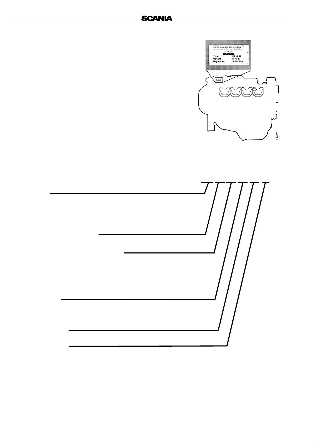
TYPE DESIGNATIONS
The engine designatio n indicates, in the form of a code, t he type of engi ne, its
size and intended use, etc.
The type designation and engine serial number are indicated on a type plate
affixed to the right- hand side of the en gine. The serial number is also punc hed
in the engine block, adj acent to the first cylinder head. Refer to the
illustration.
Engines that are cert ifie d r egardi ng smoke a nd emissi ons ar e fit ted wit h a cer tification plate specifying the documents they conform to. The plate is fitted
to rocker cover number four from the front on the right hand side.
DI 14 69 M 48 E
Type
DI Supercharged diesel engine with liquid-cooled charge air cooler
Swept volume in whole dm
3
Performance and certification code
Indicates, together with the application code, the normal gross engine
output.
The actual output setting of the engine is indicated on the engine card.
Application
M For marine use
Variant 01-99
Type of governor
E Electronically controlled governor (DEC2)
10 © Scania Industr ial & Marine Engines 2001-05:1
Page 11
31612192322
51022
25
26
2
16
22 8
10
26
25
11
20
10
21
22
713
9
25
4
9
15
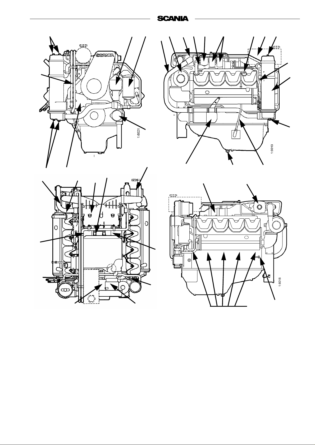
The illustrations show a typical DI14 69 engine configuration.
Your engine may have different equipment from the one shown.
1. Type plate
2. Engine serial number,
punched in engine block
3. Oil cooler
4. Oil dipstick
5. Oil cleaner
6. Oil filter, turbo
7. Drain plug, engine oil
8. Coolant pump
9. Charge air cooler (engine
coolant-cooled)
9
24
14
10. Turbocharger
11. Injection pump
12. Fuel filter
13. Starter motor
14. Alternator
15. Fan belt, adjuster
16. Coolant pipes to turbo
17. Inspection holes, engine
block
18. Drain cock, coolant
19. Oil filler cap
17
18
20. Seawater pump
21. Heat exchanger
22. Sacrificial anodes
23. Expansion tank with pres-
sure cap
24. Oil pressure monitor
25. Charge air cooler (seawa-
ter-cooled)
26. Seawater pipe to charge air
cooler
2001-05:1 © Scania Industrial & Marine Engines 11
Page 12

DEC2 CONTROL SYSTEM
This engine has an injection pump with an electromagnetic actuator which
adjusts the control rack to give the correct amount of fuel.
The system which controls the pump is called DEC2 (Digital Engine Control,
generation 2).
The control unit (DEC2) continuously receives signals from sensors for
engine speed, charge air temperature and pressure, coolant temperature, oil
pressure, throttl e positi on and cont rol rac k travel in the injecti on pump. Usin g
this input data and a control program, the correct amount of fuel for the
current operating conditions can be calculated.
The system’s sensors may be used only for DEC2, not for other instruments
or other monitoring purposes.
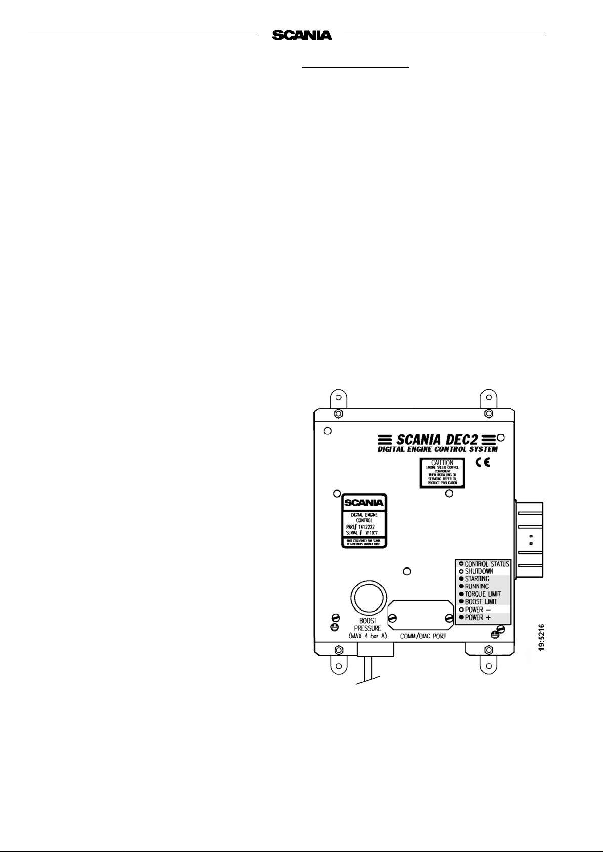
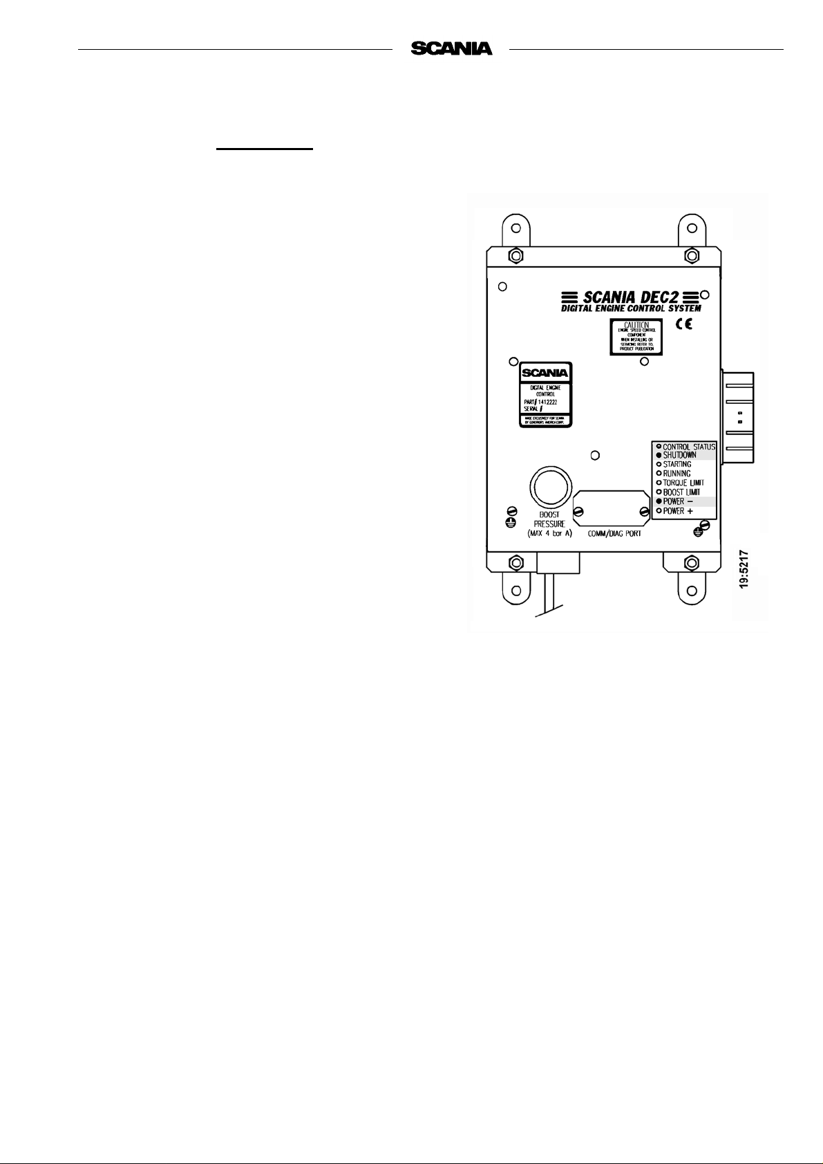
The control unit contains monitoring functions to protect the engine in the
event of a fault which would otherwise damage it. Faults and the more
important monitoring functions are indicated on the control unit in the form
of light emitting diodes. See illustration on page 14 for a description.
In case of a fault, the Power - or Shutdown indicator on the DEC2 control
unit as well as the main indicator lamp on the main supply box and the
instrument panel will illuminate.
If a fault has been indicated on the main indicator lamp the operator can
determine the cause of th e fault with the help of the LEDs on the control unit
and the troubleshooting schedule on page 17, and carry out the required
investigation and remedy.
Depending on the nature of the fault, the control system will take different
actions to protect the engine such as reducing the power output, keeping the
engine running at a constant low speed or, in case of a function impairing
fault, shutting down the engine (Shutdown).
To enable readout of LED fault codes there is a lamp test/fault code switch
located in the main supply box near the control unit.
A PC based program is also available to help service personnel to detect and
rectify fau lts and to adjust certain parameters in th e operating p rogram.
Diagnostics and changes to programs must only be performed by
authorized personnel.
The locations of the sensors and moni tors tha t send signal s to the cont rol unit
are shown in the illustrations on pages 13.
There is a description of the functions of the LEDs during normal operation
on page 14.
On page 15 there is a description of the functions of the LEDs in case of a
fault and actions in case of Power- and Shutdown indication.
Troubleshooting and fault code reading are described on pages 16 and 17.
12 © Scania Industr ial & Marine Engines 2001-05:1
Page 13
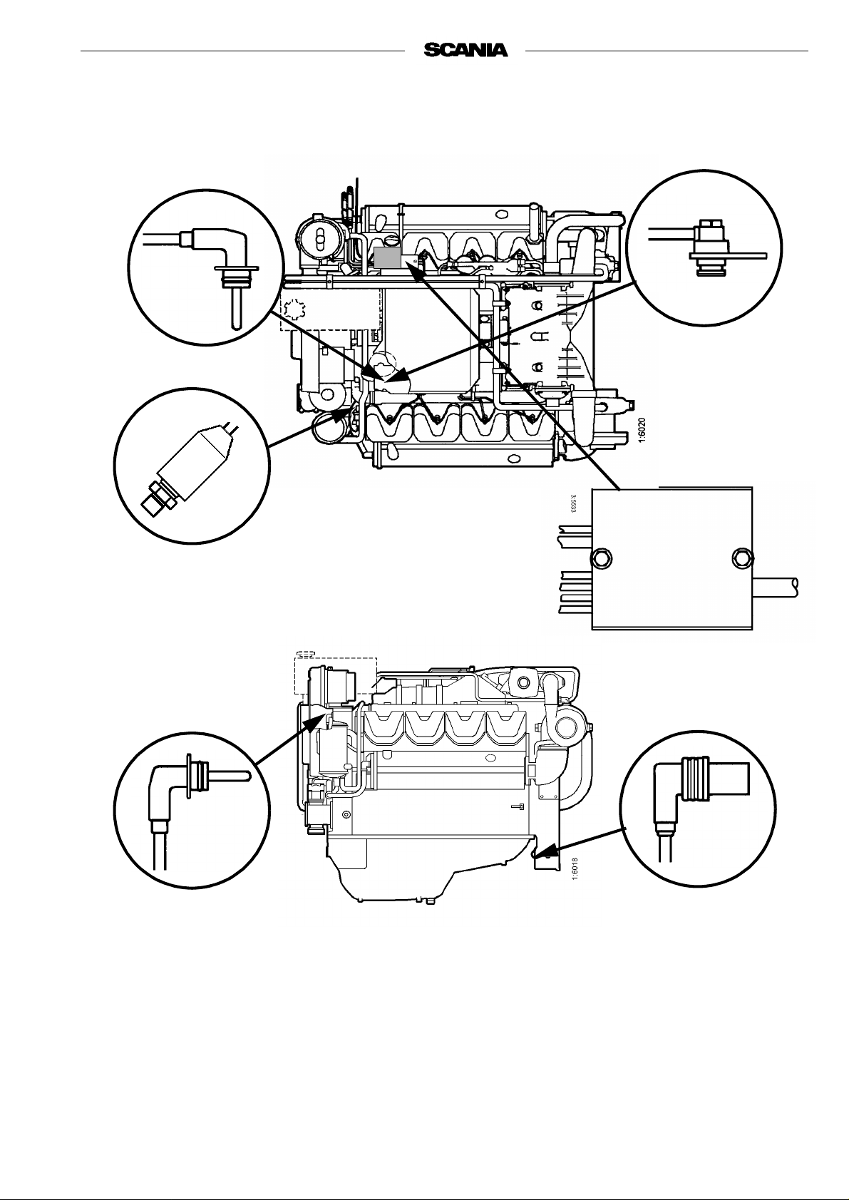
Location of sensors for DEC2
2
1
5
6
3
4
1. Connection of lead to charge air
temperature sensor
2. Charge air temperature sensor
3. Coolant temperature sensor
4. Engine speed sensors
5. Oil pressure monitor
6. Connector panel
2001-05:1 © Scania Industrial & Marine Engines 13
Page 14
LED functions during normal operation
Note: The lamp test/fault code switch should no t be
depressed. All LEDs come on briefly when
the control unit is powered up.
CONTROL STATUS
✹ The LED flashes continuousl y when the cont rol
unit is supplied with current, regardless of
whether the engine is running or not.
SHUTDOWN
❍ The LED is out.
STARTING
✹ The LED lights up as soon as the engine turns
over on cranking and follows the programmed
starting sequence until it has been completed
and then goes out.
RUNNING
✹ The LED comes on when the engine has started
and the "Starting" LED goes out. It remains on
until the engine is stopped.
POWER-
❍ The LED remains out during normal operation
as long as no fault is detected by the control
unit. See next page for the procedure to be
adopted in the event of a fault.
POWER+
✹ If the control unit is programmed to allow the
engine to be operated according to more than
one power/torque curve (map), the following
applies.
The LED comes on when the engine is run at
more than 100% power output ( MAP 2). It goes
out when the engine returns to the 100% power
output curve (MAP 1) or when the power output
required is less than 100%.
TORQUE LIMIT
✹ The LED comes on when the control unit
detects th at the engine h as received the
maximum permissible quantity of injected fu el
according to its power curve. This means 100%
power output at the curr ent rpm. If the load
increases, engine rpm will decrease.
BOOST LIMIT
✹ The LED comes on when the control unit smoke
limiter restricts the maxi mum f uel quantity.
Operation of the smoke limiter is dependent on
the charge air pressure.
14 © Scania Industrial & Marine Engines 2001-05:1
Page 15
Action in case of a fault
LED indications in case of a fault
Note The main indicator lamp in the main supply
box and at the instrument panel has
indicated a fault. The lamp test/fault code
switch should not be depressed.
CONTROL STATUS
✹ The LED will continue to flash even in case of a
fault as long as volt age is suppli ed to t he con trol
unit.
POWER -
✹ If the LED comes on, the control unit has
detected a defect that c ould cau se da mage to th e
engine if operation continues.
The control unit automatically reduces engine
power output to a predefined level if the
corresponding function has been selected.
Action: Reduce engine speed to idle if possible
and conduct troubleshooting according to
instructions on page 16 and the chart on page 17
SHUTDOWN
✹ The LED comes on and the engine is switched
off automatically in case of a severe fault that
could cause damage to the engine if operation
continues.
Action: Conduct troubleshooting according to
instructions on page 16 and the chart on page 17
If the engine has not stopped, reduce engine
speed to idle and conduct troubleshooting.
2001-05:1 © Scania Industrial & Marine Engines 15
Page 16
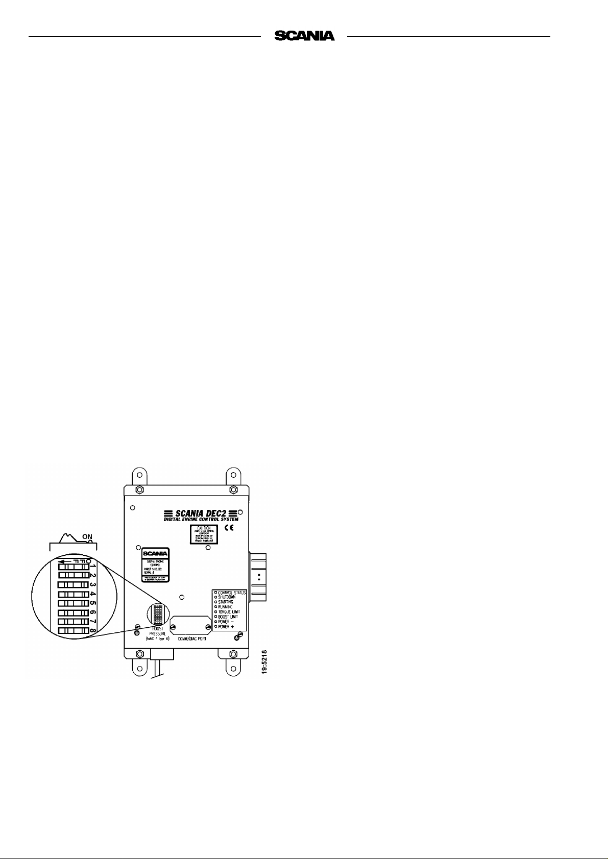
Changing functions using the DIP
switches in the control unit
There are 8 DIP switches in the control unit under the
round black rubber cover.
These switches shall be in the ON position to obtain
normal functions according to the operating program.
However, for single-speed engines, the normal
position of DIP switches 6, 7, and 8 may also be OFF
Shutdown at threshold values for low oil pressure and
high coolant temperature can be selected by setting
DIP switch 4 to OFF
With DIP switch 4 in position ON, Power- indication
is obtained for these thr eshold value s. Engine output
reduction (LOP) can be selected to prevent damage to
the engine. Changes to the program must only be
performed by authorized personnel.
Note Do not operate the engine with a Power-
indication except for in emergencies.
Readout of fault codes
Note If the engine has stopped or lost power but
the main indicator lamp is out and neither
POWER- nor SHUTDOWN are on, the
fault is outside the control unit detection
range. Probable causes: fuel shortage,
temporary overload, mechanical fault.
- Activate the lamp test/fault code switch. In
Scania electrical equipment the main indicator
lamp is located in this switch on the main supply
box.
- All LEDs will then come on for 2 seconds to
indicate that they are intact and in working order.
This also applies to the main indicat or lamp in the
main supply box and the instrument panel
a note of any LED that is defective.
- All LEDs will then be out for approximately 4
seconds.
- Following this, a fault code will be indicated on
one of the LEDs for 2 seconds. Note which LED
it is.
. Make
- The control unit then r esumes the operating mode
automatically.
- After having made a note of the fault code, reset
the lamp test/fault code switch and reset the
control unit by turning off its power supply
momentarily.
- The most probable cause of the fault can then be
found in the tr ouble shoot ing sched ule on the next
page.
- When the fault or faults have been rectified the
engine can be restarted.
- If the cont rol system continues to indicate a fault
by way of the main indicator lamp, further faults
may have been recorded. The fault code readout
must then be repeated as per above since the
system can only display one fault code at a time.
- The fault(s) will be stored in a specia l memory in
the control unit al ong with information about the
operating time when it(they) occurred. Stored
faults can be accessed and erased by authorised
service personnel.
The DIP switches are showed in ON position
16 © Scania Industrial & Marine Engines 2001-05:1
Page 17

READOUT OF FAULT CODES
Send in the control unit for repair as soon as
possible.
Check the cooling system. Check the temperature
sensor a nd cable routing.
Check the wiring and connector.
Renew the engine speed sensor.
Check the intake system. Check the temperature
sensor a nd cable routing.
Check the charge air pressure hose. Send in the
control unit for repair if the connection is damaged.
Check the cable routing, connectors and cables.
Check oil level, connector and cable.
Renew the oil pressure monitor.
Probable cause Action
DEC2 has detected an internal fault in the control unit.
The engine temperature has reached the threshold level
or the temperature sensor is inoperative.
The engine has reached the overrevving limit or the
engine speed sensor is inoperative.
Control rack position sensor inoperative. Check connectors and cables to governor.
The intake air temperature has reached the threshold
level or the charge air temperature sensor is inoperative.
DEC2 detects no charge air pressure.
The charge air pressure sensor is inoperative.
Engine speed potentiometer or the idling safety switch
is inoperative.
The oil pressure has dropped to the threshold level or
the oil pressure m onitor is inoperative.
POWER +
✹
LED INDICATION WHEN THE LAMP TEST/FAULT CODE SWITCH IS ACTIVATED
2001-05:1
POWER -
BOOST LIMIT
TORQUE LIMIT
RUNNING
✹
STARTING
✹
SHUTDOWN
✹
CONTROL STATUS
✹
© Scania Industrial & Marine Engines
✹
✹
✹
✹=LED on
17
Page 18

STARTING AND RUNNING
AT FIRST START
When the engine is starte d for the first time, the maintenance points listed
under ”First start” in the maintenance schedule should be followed, see
page 25.
Since these points are important for the engine to work satisfactorily right
from the start, they are a lso listed below.
1. Checking oil level (see page 27).
8. Checking coolant (see page 32).
The coolant should contain anti-corrosive to protect the cooling system
from corrosion.
If there is a danger of freezing:
- Only glycol anti-freeze should be used in the coolant as protection
against corrosion. We recommend only nitrite-free glycol anti-freeze
with the following supplier designations:
BASF G48 or BASF D542
- The concentration of glycol should be 30 - 50% by volume depending
on ambient temperature. 30% by volume offers protection down to
-18 °C. See page 32.
- Never top up with water only or glycol only. Lost fluid should always
be replaced with pre-mixe d coolan t with the same gl ycol cont ent as the
coolant in the engine. If the concentration of glycol drops, both antifreeze and corrosion protection will suffer.
Coolant composition:
If there is a danger of freezing:
minimum 30% glycol by volume
maximum 60 % glycol by volume
If there is no danger of freezing:
7-12% by volume
Scania Anti-corrosive
(no glycol)
Ethylene glycol and corrosion
inhibitor, if swallowed can be
fatal.
Avoid contact with the skin.
Note: A glycol concentration below 30% by volume wi ll no t provi de suf -
ficient protection against corrosion. A glycol concentration
greater than 50% will not increase anti-freeze protection and
reduces engine cooling capacity.
If there is no danger of freezing:
- Only Scania Anti-corrosive should be used in the coolant to protect
against corrosion. The correct level of anti-corrosive is 7-12% by volume and this must never drop below 7% by volume. The inhibitor in
Scania Anti-corrosive is nitrite-free.
- First fill: Fill with Scania Anti-corrosive as indicated on the packaging.
- Never top up with water only or anti-corrosive only. Lost fluid should
always be replaced with pre-mixed coolant:
water + 10% Scania Anti-corrosive by volume.
Coolant filter
Only coolant filter without inhibitor may be used. The use of a coolant filter
increases the life of the coolant and reduces the risk of deposit corrosion.
The recommended glycol must
not be mixed with glycol having
nitrite-based anti-corrosive.
The use of too much Scania
Anti-corrosive as mixed with
glycol may cause deposits.
If a coolant filter has been fitted
it must not contain inhibitor.
18 © Scania Industrial & Marine Engines 2001-05:1
Page 19

12. Checking fuel level (see page 41).
15. Checking electrolyte level in batteries (see page 43).
16. Checking battery charge (see page 43).
18. Checking coolant level monitor (see page 44).
19. Checking V-belt tension (see page 45).
CHECKS BEFORE RUNNING
Before running, ”Daily maintenance” as described in the maintenance schedule should be carried out, see page 25.
Immobilise the starting device
when working on the engine.
If the engine starts out of
control, there is a
SERIOUS RISK
OF INJURY.
STARTING THE ENGINE
If the fuel tank has been run dry or if the engine has not been used for a long
time, bleed the fuel system, see page 41.
Out of consideration for our common environment, your new Scania engine
has been designed to s tart using a smaller amount of fue l. Unnecess arily l arge
amounts of fuel used for starting the engine always result in the discharge of
unburnt fuel.
- Open the seawater system’s intake v alve (if fitted).
- Open the fuel cock (if fitted).
- Disengage the engine.
- Engines with battery master switch: Switch on the power using the battery master switch.
- DEC2: If the main indicator lamp come s on or flashes when th e power is
turned on, this indicates the presence of a fault in the control system or
engine which must be found and rectified before the engine is started.
See page 16.
- Start the engine by means of the starter button or ignition key.
Starting at low temperatures
Local environmental requirements should be complied with. Start aids,
engine heater and/or flame start should be used to avoid starting problems
and white smoke.
Only start the engine in a
properly ventilated area.
When operating the engine in
an enclosed area, an effective
extraction device for exhaust
gases and crankcase gases
must be used.
Never use starting spray or
similar as a starting aid.
An explosion may occur in the
intake pipe, which could cause
personal injury.
To limit white smoke, the engine should be run at low speed and under moderate load. Avoid running it longer than necessary at idling speed.
2001-05:1 © Scania Industrial & Marine Engines 19
Page 20

At temperatures below 0 °C:
Note: Use only start aids recommended by Scania.
- The starter motor may only be used for 30 seconds, after which it must
rest for 2 minutes.
If the engine has flame start:
- Operating flame start without timer relay: Press the control button
which also acts as a pre-glow button (max. 20 s). The glow plug continues to glow as long as the bu tton i s held down aft er th e en gine i s star ted.
Max. time is 5 minutes.
- Operating flame start with timer relay: Press the pre-glow button (max.
20 s). Release the pre-glow button after the engine starts. The timer
relay keeps the glow plug working for 5 minutes. If a shorter on-tim e is
required, press the release button. The key must be set to 0 if the start
attempt fails.
Note: If the engine is equipped with an INTERLOCK switch, this
switch should be depressed and held down until the oil pressure
has reached a sufficiently high level.
- Run the engine until warm with a light load. A light load on a cold
engine gives better c ombus tion a nd faster heati ng tha n warming u p wit h
no load.
Maximum starter engagement
time is 30 seconds. Risk of
overheating. Allow starter to
cool for 2 minutes after a
starting attempt before
cranking again.
20 © Scania Industrial & Marine Engines 2001-05:1
Page 21

RUNNING
Check instruments and warning lamps at regular intervals.
Engine speed
The Scania tachometer is divided into different coloured sectors as follows.
0-500 rpm red area: prohibited engine speed,
passed when stopping and
starting.
500-700 rpm yellow area: low idle.
700-2200 rpm green area: normal operati ng speed.
The engine’s operating
speed range is controlled by
the DEC2 control system.
2200-2600 rpm yellow/green
striped:
2600-3000 rpm red area: prohibited engine speed
unsuitable operating speed.
May occur when switching
off
Cruising speed
Important: To achieve good operating economy and long engine life,
cruising speed should be about 200 rpm below maximum
engine speed.
Coolant temperature
Normal coolant temperatur e when the en gine is run ning sho uld be 70 - 90 °C.
DEC2: If the temperature is too high, 98 °C or above, the control system will
reduce engine power (Power -) in order to lower the temperature.
If the temperature continues to rise, the engine will be stopped automatically
(Shutdown) at 103 °C.
Excessively high cool ant temperature can damage the engine.
If run for extended periods under an extremely light load, the engine may
have difficulty in maintaining normal operating temperature. However, the
temperature will rise to a normal lev el again when the load on the engine is
increased.
2001-05:1 © Scania Industrial & Marine Engines 21
Page 22

Oil pressure
Max. oil pressure:
warm engine at speed above 800 rpm 6 bar
Normal oil pressure:
warm engine at operating speed 3 - 6 bar
Min. oil pres sure:
warm engine at 800 rpm 0.7 bar
At speeds below 800 rpm, the gauge may show low oi l pressur e without there
being a fault.
Oil pressure below 0.7 bar at speeds above 800 rpm will cause engine damage. The engine must be stopped immediately.
Charge warning lamp
If the lamp lights during operation:
Check/adjust the alternator drive belts as described under maintenance point
See page 45. If the charge warning lamp is still lit, there may be a fault in the
alternator or in the electrical system.
High lubrication oil pressure
(above 6 bar) is normal when
starting a cold engine.
STOPPING THE ENGINE
1. Allow the engine to run without load for a few minutes if it has been run
with a high continuous load.
2. Stop the engine with the stop button. Keep the stop button depressed
until the engine is completely stationary.
3. DEC2: Before switching off, check that the control system’s m ain indi-
cator lamp is not on or flashing. See page 9 for trouble shooting.
4. Engines with batt ery maste r switch: t urn o ff the cur rent usi ng the ba ttery
master switch.
5. Set the control switch to ”0”.
There is danger of turbo damage
and post boiling if the engine is
stopped without cooling.
The power must not be switched
off before the engine has
stopped.
22 © Scania Industrial & Marine Engines 2001-05:1
Page 23

CHECKS AFTER RUNNING
- Check that the power is cut with the battery master switch and that the
control switch is set to ”0”.
- Fill the fuel tank. Make s ure that the ca p and the area around the filler
opening are clean to avoid contamination of the fuel.
- If there is a risk of freezing, the cooling system must be drained if it
does not contain sufficient anti-freeze, see page 32.
- Close inta ke valve for seawater (if fitted).
- If there is a danger of freezing, the seawater must also be drained .
- At temperatures below 0 °C: Pre par e for the n ext st art by conne cting the
engine heater (if fitte d).
Immobilise the starting device
when working on the engine.
If the engine starts out of
control, there is a
SERIOUS RISK
OF INJURY.
Top up engine coolant when the
engine has been stopped after
being started for the first time.
2001-05:1 © Scania Industrial & Marine Engines 23
Page 24

MAINTENANCE
The maintenance programme covers 22 points, divided into the following
main groups:
Lubrication oil system . . . . . . . . . . . . . . . . .page 26
Cooling system. . . . . . . . . . . . . . . . . . . . . . .page 30
Air cleaner . . . . . . . . . . . . . . . . . . . . . . . . . .page 39
Fuel system. . . . . . . . . . . . . . . . . . . . . . . . . .page 41
Electrical system, monitors, batteries, etc.. . page 43
Miscellaneous. . . . . . . . . . . . . . . . . . . . . . . .page 45
The maintenance points are divided into intervals as foll ows:
Daily maintenance
Maintenance before first start
Maintenance after the first 400 hours of operation
Periodic maintenance every 200 hours of operation (carried out after
200, 400, 600, 800, etc. hours)
Periodic maintenance after every 400 hours of operation (carried out after
400, 800, 1,200, 1,600, etc. hours)
Periodic maintenance after every 1,200 hours of operation (carried out after
1,200, 2,400, 3,600, etc. hours)
Immobilise the starting device
when working on the engine.
If the engine starts out of
control, there is a
SERIOUS RISK
OF INJURY
Maintenance every year
Maintenance every 3rd year
ENGINES WITH FEW HOURS OF
OPERATION
The engine is run to operating temperat ure and t he main tenanc e points below
should be carried out:
1. Checking oil level.
5. Checking coolant level.
10. Checking low pressure indicator.
12. Checking fuel level.
15. Checking electrolyte level in batteries.
16. Checking battery charge.
17. Cleaning batteries.
20. Look for leaks. Remedy as necessary
For engines with few
operating hours which do not
receive periodic maintenance
according to the maintenance
schedule on page 25,
maintenance should be
carried out according to the
schedules for:
“Every year”
24 © Scania Industrial & Marine Engines 2001-05:1
Page 25

MAINTENANCE SCHEDULE
LUBRICATION OIL SYSTEM, page 26
1. Checking oil level
2. Oil change
3. Cleaning the lubrication oil cleaner
4. Changing the turbo filter
COOLING SYSTEM, page 30
5. Checking coolant level
6. Checking corrosion protection rods 4)
7. Checking seawater pump impeller 4)
8. Chec king coolant
9. Cleaning cooling system
AIR CLEANER, page 39
10. Test reading low pressure indicator
11. Cleaning or ch anging filter insert
FUEL SYSTEM, page 41
12. Checking fuel level
13. Changing main filter
14. Checking injectors
ELECTRICAL SYSTEM, page 43
15. Checking electrolyte level in batteries
16. Checking charge state of batteries
17. Cleaning batteries
18. Checking level monitor
MISCELLANEOUS, page 45
19. Checking V-belts
20. Look for leaks. Remedy as necessary
21. Checking/adjusti ng val v e cle ara nce
22. Changing (or cleaning) valve for closed crankcase
ventilation
First time
Interval
at
Daily
At first start
400 h
200 h
400 h
l l
l1 l
l1 l
l1 l
l
l4 l
l4 l
ll5 l5
l
l l
l l2 l
l l2 l
l2 l
l l l
l l l
l
l l
At least
1200 h
Every yea r
Every 3rd year
l1 l
l3 l
l1 l
ll
l
1. More often if required
2. For engines with few operating hours, see page 24.
3. Earlier if lo w pressure i ndicator sho ws red.
4. Guiding value. Varies according to composition of seawater.
5. If inhibitor has not been topped up for three years, the coolant should be changed.
2001-05:1 © Scania Industrial & Marine Engines 25
Page 26

LUBRICATION OIL SYSTEM
OIL GRADE
The engine oil should at least meet the requirements for one of t he following
oil classifications:
-Service CE or CF as per API
-CCMC - D5
-Acea E3-96
- Check with your oil supplier that the oil meets these requirements.
- Specified oil change interv als appl y unde r the prov ision that the sulp hur
content of the fuel does not exceed 0.3% by weight.
- Viscosities as illustrated.
- At very low outside temperatures: Consult your nearest Scania representative to avoid starting difficulties.
Oil analysis
Some oil companies can offer analysis of the engine oil. This analysis measures the oil’s total base number (TBN), total acid number (TAN), fuel dilution, water content, viscosi ty and the con tent of wear partic le s and soot in the
oil.
The result of a series of anal ys es forms the basis of establishing a suitable oi l
change interval.
If the conditions are changed, a new oil analysis programme must be undertaken to es tablish a new change inter val.
Additives must not be used.
The oil should be suitable for all
temperature variations until the
next oil change.
-40 -30 -20 -10 0 10 20 30 40
SAE 20W-30
SAE 30
SAE 40
SAE 50
SAE 15W-40
°C
26 © Scania Industrial & Marine Engines 2001-05:1
Page 27

1. Daily:
CHECKING OIL LEVEL
Before checking oil level: Let the engine remain stationary for at
least 1 minute.
- The correct level is between the marks on the dipstick. Top up when the
level is at the lower mark.
- Correct type, see ”Oil grade”, page 26.
2. Every 200 hours:
OIL CHANGE
If the engine is used in particularly demanding operating
conditions, in an especially dusty environment or if the deposits in
the centrifugal cleaner are thicker than 20 mm: Change the oil
more often.
- Pump out the oil using the oil bilge pump when the engine is warm.
Max. 30 dm
Min. 25 dm
3
3
- Fill with n ew oil.
- Check the level on the dipstick.
Note: Observe the applicable environment protection regulations when
disposing of the old oil.
WARNING
The oil may be hot.
Wear protective gloves and
goggles
Maximum oil sump angles of inclination when in
operation
Maximum permissible angles for operation vary according to the type of oil
sump, see figure.
Note: Given angles may only be used intermittently.
Max. 26 dm
Min. 20 dm
Always use a suitable container
to avoid spillage when
changing oil.
Dispose of used oil through an
authorized waste disposal
contractor.
3
3
15°
45° 35°
2001-05:1 © Scania Industrial & Marine Engines 27
18°
30°
30°
Page 28

3. Every 200 hours:
CLEANING THE OIL CLEANER
(at same time as oil change)
- Unscrew the nut and remove the cover.
Open the cap carefully. The
oil may be hot.
- Lift out the rotor and slacken the nut for the rotor cover three turns.
- If the nut is stuck:
Clamp the nut, absolutely no t the ro tor, in a vice and turn the rotor three
turns by hand or using a screwdriver.
- Gently tap the nut using your hand or a plastic hammer so that the rotor
bowl becomes detached from the bottom plate.
- Undo the nut and remove the rotor bowl.
- Carefully prise the strainer loose from the bott om plate.
- Scrape away deposits from the inside of the rotor bowl. If there are no
deposits, this shows that the cleaner is not working.
- If the deposits are thicker than 20 mm: Clean more often.
28 © Scania Industrial & Marine Engines 2001-05:1
Page 29

- Clean all the parts in diesel fuel oil.
- Place the O-ring in position in the rotor bowl. This must not be damaged.
Change if necessary.
- Assemble the rotor
- Tighten the rotor nut hard by hand
- Refit the rotor.
- Check that it turns easily.
- Check that the O-ring in the bowl is not damaged.
A hardened or damaged O-ring should be replaced.
- Screw down the bowl hard by hand.
If the nut is tightened using a tool, the rotor shaft, nut or bowl may be
damaged.
Operational test
The rotor turns very quickly and should continue to rotate when the engine
has stopped.
- Stop the engine when it is warm.
- Listen for the whirring from the rotor or feel whether the cleaner housing is vibrating.
The rotor normally rotates for 30 - 60 seconds after the engine has stopped.
If not: Dismantle and check.
2001-05:1 © Scania Industrial & Marine Engines 29
Page 30

4. Every 200 hours:
CHANGING THE TURBO FILTER
(at the same time as the oil change)
- Remove the old filter and discard it according to environmental requirements.
- Oil the rubber gasket and fit a new genuine Scania filter.
- Tighten the filter by hand.
Never use tools as the filter may sustain damage, interfering with
circulation.
- Start the engine and check for leaks.
If the deposits in the centrifugal cleaner exceed 20 mm, the turbo filter
must be changed more often, at the same time as cleaning the centrifugal
filter and changing the oil.
Always collect oil in a suitable
container to avoid spillage when
renewing the oil filter.
Dispose of used filters through
an authorized waste disposal
contractor.
COOLING SYSTEM
5. Daily:
CHECKING COOLANT LEVEL
- Open the expansion tank cap and check the coolant level.
- Correct level: (Scania expansion tank)
- Cold engine: The coolant should reach up to the bottom of
the filler pipe.
- Warm engine: The coolant should be 10 - 20 mm above the bottom
of the filler pipe.
- Other types of expansion tank according to the installer’s instructions.
- Top up coolant as necessary, see point 6.
Note: When filling large amounts of coolant:
Never pour cold coolant into a warm engine.
This could crack the cylinder block and head.
Carefully open the cap.
Hot water and steam
may blow out.
Always top up with ready mixed
coolant.
30 © Scania Industrial & Marine Engines 2001-05:1
Page 31

6. Every 400 hours:
CHECKING CORROSION
PROTECTION RODS
- Drain the seawater circuit and check the corrosion protection rods
(sacrificial anodes). Location as per drawing on page 11.
- Scrape away all loose material from the anode.
- Change if less than half the rod remains.
New rods are 55 mm long, diameter 17 mm.
If the corrosion protect ion rods ar e highl y eroded, they should be c hecked
more often, e.g. every 200 hours.
7. Every 400 hours:
CHECKING SEAWATER PUMP
IMPELLER
- Close the bottom valve if the seawater pump is below the water li ne.
- Drain the seawater circuit.
- Remove the cover from the seawater pump.
- Check that the impeller vanes are not worn or damaged.
If the impeller often requires changing, it is necessary to improve
the purity of the seawater.
Changing the impeller
- Extract the impeller using extractor 98 482 (Scania special tool).
- Fit a new impeller and the cov er. Che ck that the cover seal is not
hard or damaged.
Note: A spare impeller should be carried on board.
- The impeller can bec ome deformed after long p eriods of standstill.
Change before starting or remove the impeller before long periods of
disuse. Also see “Mothballing”.
2001-05:1 © Scania Industrial & Marine Engines 31
Page 32

8. Every 400 hours:
CHECKING COOLANT
Coolant should be checked as follows:
a) Check the appearance of the coolant.
b) Coolant with glycol: Check the glycol content.
c) Coolant with Scania Anti-corrosive:
Check the corrosion protection.
The composition of the coolant is also described under
“Starting and running”.
a)
Checking the appearance of the coolant
- Take a little coolant in a vessel and check that it is clean and clear.
- If the coolant is contaminated or cloudy: Consider changing the coolant
- The water for the coolant should be free of dirt.
- Use drinking water with a pH of 6 - 9.
b)
Checking glycol content
Coolant composition:
If there is a danger of freezing:
at least 30% glycol by volume
max. 50% glycol by volume
If there is no danger of
freezing:
7-12% by volume
Scania Anti-corrosive
If there is a dan ger of f reezing, use only glycol a s protec tion aga inst corrosio n
in the coolant.
- Cooling systems with glycol must contain at least 30% glycol by volume to offer sufficient protection ag ainst corrosion.
- 30% glycol by volume provides anti-freeze protection down to -16 °C.
If more protection is required, see the table on the next page for calculating the necessary amount of glycol.
We recommend only nitrite-free glycol anti-freeze with the following sup-
plier designations:
BASF G48 or BASF D542
- Top up with glycol if the glycol content is less than 30% by volume. A
glycol content greater than 50% by volume will not provide more antifreeze protection.
- The table shows the temperature at which ice (slush) starts to form. The
engine freezes and brea ks at significa ntly lower temp eratures, see graph.
- Ice forming in the coolant often causes malfunction without any risk of
damage. The engine must not be loaded hard when ice is forming.
Note: The coolant should be changed when the cooling system is
cleaned: every 1,200 hours or at least every 3rd year.
Important: If a coolant filter is u sed in the cooling syste m, it must not
contain an inhibitor.
Ethylene glycol is highly
dangerous if ingested and can
prove fatal.
Avoid skin contact with glycol.
The coolant should be ready
mixed when it is poured into the
cooling system.
Never top up with only water or
only glycol.
The recommended glycol must
not be mixed with glycol having
nitrite-based anti-corrosive.
Risk for build up of sludge and
reduced cooling capacity.
32 © Scania Industrial & Marine Engines 2001-05:1
Page 33

Properties of glycol at low temperatures:
- Example with 30% glycol by volume
- Ice slus h starts to form at -16°C.
- There is risk for malfunctions at -30°C
No risk of damage by freezing with a minimum
content of 30% glycol by volume
A
% glycol by volume
Curve A: Ice build up starts (slush)
Curve B: Temperature at which damage due to
freezing can occur
1. Safe range
2. Malfunctions may occur (ice slush)
3.
Risk of damage by freezing
% glycol by
volume
Ice slush starts
to form at °C
Glycol dm
3
(litres)
15 20 25 30 35 40 45 50 60
Cooling
system
-6 -9 -12 -16-22-27-36-46-55
capacity, dm
5 6 8 9 1112141518 30
6 8 10 12 14 16 18 20 24 40
8 10 13 15 18 20 23 25 30 50
9 12 15 18 21 24 27 30 36 60
11 14 18 21 25 28 32 35 42 70
12 16 20 24 28 32 36 40 48 80
14 18 23 27 32 36 41 45 54 90
15 20 25 30 35 40 45 50 60 100
17 22 28 33 39 44 50 55 66 110
18 24 30 36 42 48 54 60 72 120
20 26 33 39 46 52 59 65 78 130
21 28 35 42 49 56 63 70 84 140
23 30 38 45 53 60 68 75 90 150
3
24 32 40 48 56 64 72 80 96 160
26 34 43 51 60 68 77 85 102 170
27 36 45 54 63 72 81 90 108 180
29 38 48 57 67 76 86 95 114 190
30 40 50 60 70 80 90 100 120 200
A = Range to be avoided. Only for calculation of glycol mix.
Freezing point of coolant when ice slush starts to form at different glycol mixes
2001-05:1 © Scania Industrial & Marine Engines 33
Page 34

b)
Checking Protection against corrosion
There must always be sufficient anti-corrosive (inhibitor) in the coolant to
protect the cooling system against corrosion.
If there is no danger of freezing use only Scania Anti-corrosive.
The inhibitor in Scania Anti-co rrosive is nitrite-free.
The correct level of anti-corrosive is 7- 12% by volume.
- Fill with Scania Anti-corrosive as indicated on the packaging.
- Topping up with 1.0% by volume of Scania Anti-corrosive should be
done after every 400 operating hours.
- Never top up with water only or anti-corrosive only. Lost fluid should
always be replaced with pre-mixed coolant:
water + 10% Scania Anti-corrosive by volume.
Note: The coolant should be changed when the cooling system is cleaned:
every 1,200 hours or at least every 3rd year.
Corrosion inhibitor, if
swallowed can be fatal.
Avoid contact with the skin.
Mixing corrosion inhibitor with
glycol or adding too much
corrosion inhibitor may cause
deposits and reduced cooling
capacity.
If a coolant filter has been fitted
it must not
contain inhibitor.
Changing the coolant
1. Remove the filler cap from the expa nsion tank.
2. The coolant is drained at two points:
- the ”lowest point” of the engine block, see drawing
- the ”lowest point” of the cooling system.
3. Close the drain cocks.
4. Fill coolant through the expansion tank filler hole.
Mix coolant as described on page 32.
Always collect fluid in a suitable
container to avoid spillage when
changing coolant.
Dispose of used coolant through
an authorized waste disposal
contractor.
34 © Scania Industrial & Marine Engines 2001-05:1
Page 35

9. Every 1200 hours:
CLEANING THE COOLING SYSTEM
Note: If n ecessary, the cooling system should be cleaned more often.
External cleaning
Heat exchanger
Drain the coolant from the engine, see “Changing coolant”.
1.
2. Close the bottom valve or valves and drain the seawater circuit.
3. Disconnect the heat exchanger’s seawater pipe connections and the con-
nections to the charge air coolers, oil cooler and block.
4. Remove the heat exchanger assembly and dismantle it as illustrated.
5. Clean the outside of the element. Use a paraffin-based engine cleaner.
6. Remove any deposit on the inside of the pipes using a round file.
7. Assemble the heat exchanger. Change damaged and hardened O-rings.
8. Make sure that the thermostats are in place and fit the heat exchanger
back in place on the engine. Reconnect the pipes to the charge air coolers and oil cooler and also the return line from the block.
9. Fill the sy stem with coo lant as described in the specifications on
page 32.
The cooling system must never
be cleaned with caustic soda.
There is a risk of damage to
aluminium parts.
There are springs and retainers
in the heat exchanger, between
the housing and th e ele m en t ,
which are not illustrated.
1. Housing
2. Spiral pin
3. Element
4. O-ring
5. Gasket
6. Gasket
7. Cover
8. Bolt
9. Washer
10. Cover
11. Bolt
12. O-ring
13. Plug
14. Sacrificial anode
2001-05:1 © Scania Industrial & Marine Engines 35
15. Gasket
16. O-ring
17. Bolt
18. Gasket
19. Flange pipe
20. Gasket
21. Bolt
22. Bolt
23. Plug
24. Washer
25. Washer
26. Bolt
27. Bolt
Page 36

Seawater-cooled charge air cooler
1. Disconnect the connecting pipes for air and seawater and remove the
charge air cooler assembly.
2. Dismantle the charge air cooler as illustrated.
3. Clean the outside of the element. Use a paraffin-based engine cleaner.
4. Remove any deposit on the inside of the pipes using a round file.
5. Assembly the charge air cooler . Change any dama ged and hard O-rings .
6. Refit the charg e air cool er as semb ly af ter the seawa ter-c ooled charg e air
coolers have been cleaned and assembled.
Tighten bolt 8 to 9±2 Nm.
Note: On assembly, silicone (816 064) should be applied t o bot h si des of
new gaskets 13.
7. Refit the pipe connections for air and seawater.
1. Housing
1. Housing
2. Element
2. Element
3. Spiral pin
3. Spiral pin
4. Spacer
4. Spacer
5. O-ring
5. O-ring
6. Cover
6. Cover
7. Bolt
8. Bolt
8. Bolt
9. Washer
9. Washer
10. Bolt
10. Bolt
11. Bolt
11. Bolt
12. Washer
12. Washer
13. Gasket (2)
7. Bolt
36 © Scania Industrial & Marine Engines 2001-05:1
Page 37

Coolant-cooled charge air cooler
1. Drain the coolant from the engine, see “Changing the coolant”, and
drain the seawater circuit if this has not been done when cleaning the
heat exchanger.
2. Remove the catwalk, delivery pipes, fuel filter and water pipes to the
turbo unit.
3. Remove the rear, transverse charge air cooler (seawater-cooled).
4. Undo the charge air cooler’s inlet and outlet pipe connections.
5. Dismantle the charge a i r cooler as illustrated.
Exercise care - do not damage the element’s water connections.
6. Clean the outside of the element. U se a paraffin-based engi ne cleaner.
7. Clean and degrease the sealing surfaces on the core and the air intake
manifold upper and lowe r parts with a spirit based cleaner.
8. Apply sealant (silicone 816 064) in a uniform bead, approximately
2-3 mm, on both sealing surfaces of the element.
9. Fit new V-ring seals on the connections of the element.
10. Assemble the charge air cooler within 15 minutes of applying the sea-
lant. Torque tighten the bolts to 50 Nm.
11. Reconnect the inlet and outlet pipe connections and refit the delivery
pipe, fuel filter and other parts that have been removed.
12. Refit the transver se charge a ir cooler and its pipe c onnecti ons for ai r and
seawater.
Note: On reassembly, apply silicone to the sealing surfaces against the
seawater-cooled char ge air cooler and its gaskets.
13. Fill up with coolant as per the specifications on page 32.
Important Allow the sealant to cure for minimum
24 hours before the engine is used.
The cooling system must never
be cleaned with caustic soda.
There is a risk of damage to
aluminium parts.
1. Intake manifold,
lower part
2. Radiator element
3. Intake manifold,
upper part
4. V-ring seal
5. Sealant 816 064
2001-05:1 © Scania Industrial & Marine Engines 37
Page 38

Internal cleaning
Removing oils and greases
- If possible, run the engine until it is warm and then drain the cooling
system.
- Remove the thermostats. This will necessitate removal of the heat
exchanger assembly. It is therefore advisable to do this in connection
with cleaning the heat exchanger.
- Fill the system with clean, hot water mixed with liquid dishwasher
detergent designed for household machines. Mix 1% (0.1/10 l).
- Warm up the engine for about 20 or 30 minutes. Do not forget the cab
heating system, if any.
- Drain the cooling system.
- Fill the system again using cl ean, hot water and r un the engi ne for ab out
20-30 minutes.
- Drain the water from the system.
- Refit the thermostats.
- Fill the system with coolant as described in the specifications on
page 32.
Removing deposits
- If possible, run the engine until it is warm and then drain the cooling
system.
- Remove the thermostats. This will necessitate removal of the heat
exchanger assembly. It is therefore advisable to do this in connection
with cleaning the heat exchanger.
- Fill the s ystem with clean, hot water mixed with one of the com mercially available radiator cleaners based on sulphamic acid and containing dispersing agents. Follow the manufacturer’s instructions for mix
ratios and cleaning times.
Handling cleaning agents for
the cooling system:
Read the warning label on the
container.
Always collect fluid in a suitable
container to avoid spillage when
draining coolant.
Dispose of used coolant through
an authorized waste disposal
contractor.
- Run the engine for the specified time and then drain the cooling system.
- Fill the system again with hot water and run the engine for about 20 or
30 minutes.
- Drain the water from the system.
- Refit the thermostats.
- Fill the system with coolant as described in the specifications on
page 32.
Preventive replacement of coolant pump gear
Note: To be carried out in connection with cleaning of the cooling
system.
- Remove the coolant pump.
- Remove the drive gear.
- Fit a new gear and tighten the nut to 200 Nm.
Note: D o not apply the tightening to rque to the gea r itself.
- Refit the coolant pump, using new gaskets for the timing gear cover.
38 © Scania Industrial & Marine Engines 2001-05:1
Page 39

AIR CLEANER
10. Daily:
TEST READING
LOW PRESSURE INDICATOR
If the indicator’s red plunger is fully visible, change or clean the air cleaner
filter insert, point 11.
11. Every 1,200 hours:
CLEANING OR CHANGING THE
FILTER INSERT
Note: Earlier if low pressure indicator shows red.
Dismantling
1. Remove air cleaner’s side cover.
2. Change or clean the insert.
Note: Cleaning the insert always entails a risk of damage. The insert
may be cleaned no more than four times. A fter cleaning, it has a
lower dust capacity than a new insert.
3. Mark the filter when it has been cleaned.
Cleaning insert
- Careful ly blow the filter insert clean using dry compressed air from the
inside.
Note: This insert must not be washed using water.
1
Only use Scania genuine air
filter. Change the filter element
if it is damaged.
Danger of engine damage if the
filter element is damaged.
Never start the engine unless
the air filter is installed.
Danger of personal injury or
engine damage.
2
3
1. Cover
2. Filter insert
3. Filter housing
2001-05:1 © Scania Industrial & Marine Engines 39
Page 40

Checking
- Insert a flashlamp into the insert and check from the outside that there
are no holes or cracks in the filter paper.
- Change the filter insert if there is any damage at all. Danger of engine
damage.
Assembly
1. Assemble the air cleaner in reverse order.
2. Reset the red plunger in the low pressure indicator by pressing in the
button.
Filter with non-replaceable insert (unit cleaner)
Cleaning
- The filter must be clean ed no mor e th an 3 times. Make a mark on it each
time it is cleaned.
- Use a washing solution consisting of water mixed with about 1% mild
detergent.
1. Pour the washing s o lu ti on into the filter outlet while t urning the filter so
that the solution runs out of it opposite to the direction of air flow.
2. Leave the filter in the washing solution for 5 minutes and then lift it to
drain off the solution.
3. Rinse the filter with about 30 litres of clean water at 30 - 40 °C. Pour the
rinse water into the filter in the same way as the washing solution.
4. Lift the filt er and allow t he rinse water to drain.
5. Repeat this procedure until the rinse water runs clear.
6. Leave the filter to dry in a warm place for a day or so.
Note: The filter must not be blown dry using compressed air.
40 © Scania Industrial & Marine Engines 2001-05:1
Page 41

FUEL SYSTEM
12. Daily:
CHECKING THE FUEL LEVEL
- Top up fuel if necessary.
- If the tank is run dry, bleed the fuel system, see point 13.
13. Every 1200 hours:
CHANGING THE FUEL FILTER
Fuel tanks
- Drain any water from the fuel tanks.
Filter
The filter consists of two filter units connected in parallel.
- Wash the outside of the filters and unscrew them. Dispose of the filters
according to environmental regulations.
Be extremely careful with
cleanliness when working on
the fuel system.
Malfunctions
can easily arise and the
injection equipment
can be damaged.
- Tighten the new filters by hand.
Never use tools. The filters may be damaged, inhibiting circulation.
- Bleed the fuel system as described below.
- Start the engine and check for leaks.
Bleeding the fuel system
- Open bleed screw 1 on the main filt er.
- Pump hand pump 2 until air-free fuel flows out at the main bleed screw.
- Close the bleed screw. Pump a few times using the hand pump.
If the engine is difficult to start after bleeding . . . . .
- Slacken injection pump overflow valve 3 half a turn
and make a fresh attempt to start.
If the engine still won’t start . . . . . . .
- Pump the hand pump until bubble-free fuel flows from the overflow
valve.
Tighten the overflow valve when the engine has started.
Only use Scania genuine fuel
filter.
Always collect fuel in a suitable
container to avoid spillage when
bleeding system or renewing
components.
2
3
2001-05:1 © Scania Industrial & Marine Engines 41
Page 42

14. Every 1,200 hours:
CHECKING INJECTORS
Injectors should be inspected by trained personnel with access to the required
equipment, at least once every year or every 2,400 hours.
Removal
1. Clean around the injectors and connections including clamps and
brackets.
2. Undo the leak-off pipes and bunch of delivery pipes. Be careful to
avoid bending any of the delivery pipes.
3. Unscrew the injector.
4. Place protective plugs on the injector and delivery pipe.
5. Lift the seal from the bottom of the injector seat if it does not come out
together with the injector.
6. Place a seal plug in the injector seat in the cylinder head.
7. Clean the injectors and check/adjust in an injector tester.
Correct opening pressure, see Technical data, page 52.
Fitting
1. Check that there is no old seal in place and fit a new seal in the bottom
of the injector seat.
2. Fit a new O-ring in the socket nut and a new seal under it.
3. Fit the injector.
4. Tighten the socket nut to 70 Nm (7.0 kgfm).
5. Fit the delivery pipe and tighten the cap nuts to 20 Nm (2.0 kgfm).
Fit clamps and brackets.
Take care to fit the delivery pipe without tension and make sure that
the con e on the deliv ery pipe is correctly positioned in the connection.
1. Socket nut
2. O-ring
3. O-ring
4. Stop ring
5. Guide pin
6. Seal
The delivery pipes must
not be bent.
All clamps must be refitted.
Always wear gloves and eye
protection when testing
injectors.
Fuel escaping under high
pressure can penetrate body
tissue and cause serious injury.
6. Fit the leak-off fuel line. Tighten the bolts to 11 Nm (1.1 kgfm).
1. Delivery pipes
2. Cap nut
3. Washer
4. Cone
5. Connection on injector or
injection pump
Delivery pipe connection
42 © Scania Industrial & Marine Engines 2001-05:1
Page 43

ELECTRICAL SYSTEM
15. Every 200 hours:
CHECKING THE ELECTROLYTE
LEVEL IN BATTERIES
1. Unscrew the plugs and check the electrolyte level in all cells.
2. Top up with distil le d wat er un ti l the level is 10-15 mm above the plat es .
16. Every 200 hours:
CHECKING THE CHARGE STATE
OF THE BATTERIES
- Check the specific gravity using a hydrometer (battery electrolyte
tester).
In a fully charged battery it should be:
1.280 at +20 °C
1.294 at 0°
1.308 at -20 °C
Do not let open flame or sparks
come near the batteries.
When batteries are charged,
they emit highly flammable
fumes that can explode.
Wear gloves and eye protection
when charging and
handling batteries.
Batteries contain a highly
corrosive acid.
- If the specific gravity is below 1.20, the battery must be charged.
A discharged battery freezes at -5 °C.
- Trickle charging is recommended during the winter if the engine is not
used.
Avoid boost charging. This will damage the battery in the long term.
17. Every 200 hours:
CLEANING BATTERIES
1. Clean batteries, cables and cable terminals.
2. Check that all cable terminals are well tightened.
3. Grease posts and cable terminals using petroleum jelly.
Do not connect the cables to the
wrong terminals.
This could cause serious
damage to the electrical system.
If the terminals are
shortcircuited, sparks
will be generated.
2001-05:1 © Scania Industrial & Marine Engines 43
Page 44

CHANGING BATTERY
Removal
1.
Detach the negative lead (-) from the battery (cable to engine casing).
2. Detach the positive lead (+) from the battery (cable to starter motor).
Fitting
1. Connect the positive lead (+) to the batt ery (cable to s tarter motor).
2. Connect the negative lead (-) to the battery (cabl e to engine ca sing).
Do not connect the cables to the
wrong terminals.
This could cause serious
damage to the electrical system.
If the terminals are short-
circuited, sparks will be
generated.
Dispose of used batteries
through an authorized waste
disposal contractor.
18. Every 400 hours:
CHECKING THE COOLANT LEVEL
MONITOR
(optional equipment)
Note: The level monitor should be checked when the engine is cold.
1. Undo the clamps on the level monitor’s lead to the wiring harness on the
engine and unplug the connector.
2. Place a receptacle under the coolant pump and unscrew the monitor.
Immediately fit a plug with an M18x1.5 thread in the hole for the monitor. Avoid getting the coolant on your skin.
3. Plug in the monitor’s connector and set the control switch to ”ON”.
4. Check that the indicator lamp remains on and that the buzzer sounds.
5. Submerse the monitor in liquid in a metal recepta cle (steel). It is impor-
tant to ensure that the body of the monitor is in contact with the metal.
6. The indicator lamp should go out after about 2 seconds.
7. Remove the monitor from the liquid. In about 7 sec onds the indicator
lamp should come on and the buzzer start to sound.
8. Unplug the monitor’s co nnector and s crew the monitor back in place.
2-pole level monitor
9. Clamp the monitor’s lead as before and plug in the connector.
10. Fill the system with coolant as described in the specifications on
page 32.
44 © Scania Industrial & Marine Engines 2001-05:1
Page 45

MISCELLANEOUS
19. Every 200 hours:
CHECK/TENSION
V-BELTS
If correctly tensioned, a pr ess ure of 35-50 N on a drive belt
(depending on the free length of the belt) should deflect it
about 10 mm.
Change worn or damaged belts.
1. Detach the securing screws.
2. Set the correct tension using the adjusting screw.
Do not overtighten the belts.
Measurement using a Krikit belt tension gauge
(Part. No. 587 495)
Zero the gauge by pressing the measuring arm.
1.
2. Place the gauge on the V-belt at an equal distance from two pulleys.
3. Press until the gauge clicks.
4. Read the gauge.
- The recommended tension of genuine Scania belts
when tested is 300 N.
When changing belts, slightly higher (10-15%) tension should be used.
2001-05:1 © Scania Industrial & Marine Engines 45
Page 46

20. Daily:
LOOK FOR LEAKS,
REMEDY AS NECESSARY
- Start the engine.
- Look for leakage of oil, coolant, fuel, air and exhaust.
- Tighten or change leaking connections. Check the overflow holes (1)
which show whether the O-rings between the cylinder liner and crankcase are leaking, see drawing.
a) If coolant is leaking out, the two upper O-rings are leaking.
b) If oil is leaking out, the lower O-ring is leaking.
- Check that the drain hole (2) on the coolant pump is not blocked, see
drawing. If there is leakage, change the pump seal.
- Check that the drain for the “V” behind the injection pump is open all
the way through the block and drain pipe so that no fluid can collect in
the “V”. See drawing.
A small amount of leakag e from the ove rflow hole s when run ning-in t he
engine is normal. (Seals and O-rings are fitted lubricated with soap or
oil).
This leakage normally stops after a time.
If there is a large amount of leakage - contact your nearest Scania
workshop.
Ensure that any leakage does
not pollute the environment.
In case of major leakage,
contact the nearest Scania
workshop.
46 © Scania Industrial & Marine Engines 2001-05:1
Page 47

21. Every 1,200 hours:
e
s
CHECKING/ADJUSTING
VALVE CLEARANCE
Checking/adjusting valve clearance should be done after the
first 400 hours of operation.
Valves should be adjusted when the engine is cold, at least 30 minutes after
running.
Rocker cover gaskets should be changed as necessary. Tightening torque:
25 Nm.
Alternative 1
- Turn the crankshaft in its direc tion of rotatio n until the piston in cyl inder
No. 1 is 30°after TDC on the combustion stroke. There is a mark, ⊥, at
this position.
- Adjust the following valves:
Right side Cyl 1 Intake and exhaust
2Ex
4Ex
Left side Cyl 5 In and ex
7In
8In
- Turn the crankshaft one revolution in its direction of rotation to the
⊥ m ark. The piston in cylinder No. 1 will then be 30°after TDC on the
induction stroke.
- Adjust the following valves:
Right side Cyl 2 In
3 In and ex
4In
Left side Cyl 6 In and ex
7Ex
8Ex
WARNING
Immobilise the starting device
when working on the engine.
If the engine starts out of
control, there is a
SERIOUS RISK
OF INJURY.
1
5
2
6
3
7
4
8
FLYWHEEL
Cylinder numbering
No. 1 cylinder piston 30°after
TDC in
combustion
stroke
induction
stroke
Important.
On silumin housings, reading is possibl
only from underneath.
On ductile cast iron h ousings, r eading i
possible from underneath or from the
side (60°), depending on accessibility.
FLYWHEEL
Covers for reading
on flywheel casing
2001-05:1 © Scania Industrial & Marine Engines 47
Intake valve
Exhaust valve
Page 48

Alternative 2
- Set the No. 1 cylinder to TDC by turning the engine in its direction of
rotation until both valves are closed.
- Adjust both the valves for the No. 1 cylinder. Correct valve clearance is
indicated on the instruction plate on one of the rocker covers.
- Repeat this procedure with the remaining cylinders in the order 5 - 4 - 2
- 6 - 3 - 7 - 8 (firing order) by turning the engine 1/4 revolution in its
direction of rotation between each adjustment.
22. Every 1,200 hours:
CHANGING (or CLEANING) VALVES
FOR CLOSED CRANKCASE
VENTILATION
Alternative 1:
Change the valves at the specified interval.
Alternative 2:
- Remove the valves at th e specified in terval.
- Clean the valves by placing them in a bath of diesel oil overnight.
Then rinse them several times in diesel oil and leave them to drain off.
- Refit the valves.
- The valves may be reused (cleaned) no m ore than twice after the
first 1,200 hours of use. Be sure to mark the valves in connection
with cleaning them.
48 © Scania Industrial & Marine Engines 2001-05:1
Page 49

LONG-TERM STORAGE
If the engine is not to be used for a lengthy period of time, special measures
should be taken to protect the cooling system, fuel system and combustion
chamber from corrosion and the exterior from rusting.
The engine can normally stand idle for up to six months. If it remains unused
for longer than this the following measures, which provide protection for
about four years, should be adopted. An alternative to preparing the engine
for long-term storage is to start the engine and warm it up every 6 months.
Preparing the engine for long-term storage means:
- Thoroughly cleaning the engine
- To run the engine for a period of time with preservative fuel,
preservative oil and preservative coolant.
- Otherwise preparing the engine for storage (filter changes, lubrication,
etc.).
-
Preservative coolant
If the engine is to be stored with a full cooling system, use coolant containing
50% glycol by volume. Glycol without nitrite-based inhibitor must be used.
E.g. BASF G48 or BASF D542.
Ethylene glycol, if swallowed
can be fatal.
Avoid contact with the skin.
Preservative fuel
- Use diesel fuel mixed with Lubrizol 560A or equal.
3
-Mix 1 cm
(ml) of Lubrizol 560A with 10 dm3 (l) of fuel.
!
HANDLING LUBRIZOL 560A
Hazardous!
Contains aromatic hydrocarbons
Use spot extractors where there is a danger of vapour build-up.
Wear protective gloves and goggles when handling Lubrizol. Do not use contaminated clothing.
In case of splashes in the eye: Rinse with moderate water spray (for min. 15 minutes). Seek medical attention.
In case of skin contact: Wash affected areas with soap and water.
If you inhale it: Fresh air, rest and warmth
Flammable: Fire class 2A. Flash point + 27°.
In case of fire: Extinguish using carbonic acid, powder or foam
Storage: In properly sealed container in a dry, cool place. Keep out of reach of children.
2001-05:1 © Scania Industrial & Marine Engines 49
Page 50

Preservative oil
Suitable preservative oil can be supplied by most oil companies.
E.g. Dinitrol 40 or the equivalent.
Preparations for storage
- Drain and flush the cooling system. Fill with preservative coolant.
- Run the engine until warm with or dinary fuel. Stop the engine and drain
the oil.
- Change fu el filter and turbo filter.
- Fill the engine with
dipstick.
-Mix the
suction line and connect a hose from the can.
- Detach the fuel pipe at the overflow valve and connect a return hose to
the can.
- Start the engine and run it at about 1000 rpm for 20 - 25 minutes.
- Stop the engine, remove the hoses and connect the normal fuel lines.
preservative fuel in a ca n. Detac h the f uel pi pe at the f eed pump
preservative oil to the minimum level on the
Always use suitable containers
to avoid spillage when
draining oil and coolant.
Dispose of used oil and coolant
through an authorized waste
disposal contractor.
- Oil the valve mechanism with plenty of
- Remove the injectors and spray
max. 30 cm
Crank the engine several revolutions using the starter motor. Spray a
small amount into each cylinder.
The engine must not then be cranked. Refit the injectors.
- Drain the
directly or when taken out of
- Drain the coolant if the engine is not to be stored with a full cool ing system. Plug and tape over a ll coolant connections (if the cooling s y st em i s
not completely assembled).
- Air cleaner: Clean and change the filter insert.
- Cover air intakes and exhaust pipes.
- Alternator and starte r motor:
- Spray with water-repellent anti-corrosive oil, CRC 226, LPS1 or the
equivalent.
- Spray the outside of shiny engine parts, first using penetrating
tive
oil such as Dinitrol 25B and then using Dinitrol 112 or the
equivalent.
3
(ml).
preservative oil from the engine. New engine oil can be filled
preservative oi l into each cylinder
preservative.
preservative oil.
preserva-
50 © Scania Industrial & Marine Engines 2001-05:1
Page 51

- Attach a c lear notice to the engine with the date of preservation and
stating that the engine must not be started or cranked.
STORED ENGINE
Date . . . . . . . . . . .
Must not be started or cranked.
Batteries
Remove the batterie s for mainten anc e char ging i n the c hargi ng s tation. ( Does
not apply to batteries which, according to the manufacturer, are maintenancefree). The same also applies to short periods of disuse, even if the engine is
not stored as above.
Taking out of storage
(action when the engine is taken into service)
- Remove plugs and tape from coolant connections, air intakes and
exhaust pipes.
- Fill the cooling system with coolant, see page 18.
- Check the oil level in the engine and top up with new oil.
- Crank the engine several revolutions with the injector s removed, oiling
the valve mechanism, pushrods and tappets with plenty of oil.
Important: The engine must be cranked with the injectors removed so
that excess
- Fit the injectors.
- Drain the fuel system’s main filter of
- Bleed the fuel system.
preservative oil can be forced out of the cylinders.
preservative fuel .
- Wash off externally applied
preservative oil using white spirit.
Winter storage
The fuel tank or tanks should be filled up during winter storage to reduce the
risk of condensate forming.
2001-05:1 © Scania Industrial & Marine Engines 51
Page 52

TECHNICAL DATA
GENERAL DI14
Number of cylinders
Cylinder bore mm
Stroke mm
3
Swept volume dm
Number of main bearings
Firing sequence
Compression ratio
Engine direction of rotation viewed from rear
Cooling
Valve cl earance, cold engine:
intake valve mm
exhaust valve mm
Weight: (without coolant and oil) kg
Power
(litres)
V8, 90
1 - 5 - 4 - 2 - 6 - 3 - 7 - 8
Anticlockwise
see “Engine record card”
°
127
140
14.2
5
13.5:1
Fluid
0.45
0.80
1350
LUBRICATION SYSTEM
Max. oil pressure
(warm engine at speed above 800 rpm) bar (kgf/cm
Normal oil pressure
(warm engine at operating speed) bar (kp/cm
Min. oil pressure
(warm engine 800 rpm) bar (kp/cm
Oil capacity, see page 27.
2
)
2
)
2
)
6
3 - 6
0.7
52 © Scania Industrial & Marine Engines 2001-05:1
Page 53

FUEL SYSTEM DI14
Pump setting BTDC
2
Injectors, opening pressure bar (kgf/cm
Low idle rpm
Maximum full load speed
Fuel
Tightening torques:
Socket nut for injectors Nm
Cap nut for delivery pipe Nm
Oil leakage connection Nm
1)
see page 54
)
COOLING SYSTEM
Number of thermostats
Thermostat, opening tempera tu re
Thermostat in charge air circuit,
opening temperature
°C
°C
See plate on rocker cover
300
700
See engine card
Diesel fuel oil
70
20
11
2
79±2
50±2
1)
Coolant temperature:
3
(litres)
°C
system with overpressure
Volume: dm
ELECTRICAL SYSTEM
System voltage V
Alternator, current A
Starter motor power kW (hp )
Monitors, settings:
oil pressure monitor bar (kgf/cm
temperature monitor °C
2
70 - about 100
about 95
24
65 or 120 or 2x65
6.7 (9.1)
)
Stamped on monitor hexagon
2-pole:0.7
±0.15
2001-05:1 © Scania Industrial & Marine Engines 53
Page 54

FUEL
Diesel fuel
The composition of the diesel fuel is vitally important to the operation and
life of the engine and the fuel injection pump. The engine power output and
the exhaust emissions are also dependent on the fuel quality.
The requirements and the test standards for the most important properties are
described in the workshop manual in sections that can be ordered from your
Scania dealer or directly from Scania. The address of Scani a i s p ri nte d on the
cover.
The diesel fuel shall comply with the following standard:
EN 590 (European standard).
The table below shows the requirements for some of the most important
properties:
Property Requirement
Viscosity at 40°C 2.0 - 4.5 mm
Density at 15°C 0.82 - 0.86 kg/dm
Sulphur (concentration by mass) max. 0.3%
Ignitability (CET rating) min. 49
Flashpoint 56°C
2
/s (cSt)
3
Environmentally favourable fuels (low sulphur fuels)
Additives must not be used.
There are three different grades of so called environmentally favorable fuels
(SS15 54 35). Grade 1 is sulphur-free and gr ade 2 is low in sulphur.
Compared with class 3 (normal fuel), these fuels are less dense and this
reduces engine power output. Only class 1 fuel should be used with a
catalytic converter.
Short term use of fuel with a higher sulphur content than 0.05% by weight
will not cause permanent damage to the catalytic converter.
The catalytic converter may, however, require fuel with low sulphur content
for some time after this to regain its normal efficiency.
54 © Scania Industrial & Marine Engines 2001-05:1
Page 55

ALPHABETICAL INDEX
Air cleaner . . . . . . . . . . . . . . . . . . . . . . . . . . . . 39
Air cleaner, low pressure indicator . . . . . . . . . 39
Air filter, insert . . . . . . . . . . . . . . . . . . . . . . . . 39
Batteries . . . . . . . . . . . . . . . . . . . . . . . . . . . . . 43
Battery, changing . . . . . . . . . . . . . . . . . . . . . . 44
Bleeding, fuel system . . . . . . . . . . . . . . . . . . . 41
Certified engines . . . . . . . . . . . . . . . . . . . . . . . . 5
Charge air cooler . . . . . . . . . . . . . . . . . . . . . . . 36
Checks after running . . . . . . . . . . . . . . . . . . . . 23
Checks before running . . . . . . . . . . . . . . . . . . 19
Clutch . . . . . . . . . . . . . . . . . . . . . . . . . . . . . . . 23
Commissioning report . . . . . . . . . . . . . . . . . . . . 1
Coolant . . . . . . . . . . . . . . . . . . . . . . . . . . . . . . 32
Coolant level . . . . . . . . . . . . . . . . . . . . . . . . . . 30
Coolant level monitor . . . . . . . . . . . . . . . . . . . 44
Coolant temperature . . . . . . . . . . . . . . . . . . . . 21
Coolant, changing . . . . . . . . . . . . . . . . . . . . . . 34
Cooling system . . . . . . . . . . . . . . . . . . . . . . . . 30
Cooling system, cleaning the . . . . . . . . . . . . . 35
Corrosion protection rods . . . . . . . . . . . . . . . . 31
Crankcase ventilation, closed . . . . . . . . . . . . . 48
Injectors . . . . . . . . . . . . . . . . . . . . . . . . . . . . . . 42
Leakage . . . . . . . . . . . . . . . . . . . . . . . . . . . . . . 46
LED functions . . . . . . . . . . . . . . . . . . . . . . . . . 14
Long-term storage . . . . . . . . . . . . . . . . . . . . . . 49
Low pressure indicator . . . . . . . . . . . . . . . . . . 39
Lubrication oil pressure . . . . . . . . . . . . . . . . . . 22
Lubrication oil system . . . . . . . . . . . . . . . . . . . 26
Maintenance . . . . . . . . . . . . . . . . . . . . . . . . . . 24
Maintenance schedule . . . . . . . . . . . . . . . . . . . 25
Oil analysis . . . . . . . . . . . . . . . . . . . . . . . . . . . 26
Oil capacity . . . . . . . . . . . . . . . . . . . . . . . . . . . 27
Oil change . . . . . . . . . . . . . . . . . . . . . . . . . . . . 27
Oil cleaner . . . . . . . . . . . . . . . . . . . . . . . . . . . . 28
Oil grade . . . . . . . . . . . . . . . . . . . . . . . . . . . . . 26
Oil level . . . . . . . . . . . . . . . . . . . . . . . . . . . . . . 27
Oil pressure . . . . . . . . . . . . . . . . . . . . . . . . . . . 22
Protection against corrosion . . . . . . . . . . . . . . 34
Running . . . . . . . . . . . . . . . . . . . . . . . . . . . . . . 21
DEC2 Control system . . . . . . . . . . . . . . . . . . . 12
Electrical system . . . . . . . . . . . . . . . . . . . . . . . 43
Engine speed . . . . . . . . . . . . . . . . . . . . . . . . . . 21
Environmental responsibility . . . . . . . . . . . . . . 4
Fault codes DEC2 . . . . . . . . . . . . . . . . . . . . . . 16
Filter, air cleaner . . . . . . . . . . . . . . . . . . . . . . . 39
Filter, fuel . . . . . . . . . . . . . . . . . . . . . . . . . . . . 41
First start . . . . . . . . . . . . . . . . . . . . . . . . . . . . . 18
Foreword . . . . . . . . . . . . . . . . . . . . . . . . . . . . . . 2
Fuel filter, changing . . . . . . . . . . . . . . . . . . . . 41
Fuel level . . . . . . . . . . . . . . . . . . . . . . . . . . . . . 41
Fuel specifications . . . . . . . . . . . . . . . . . . . . . 54
Fuel system . . . . . . . . . . . . . . . . . . . . . . . . . . . 41
Fuel system, bleeding . . . . . . . . . . . . . . . . . . . 41
Glycol . . . . . . . . . . . . . . . . . . . . . . . . . . . . . . . 32
Safety details . . . . . . . . . . . . . . . . . . . . . . . . . . . 6
Safety precautions for care and maintenance . . 8
Safety precautions for handling materials . . . . . 8
Safety precautions for operation . . . . . . . . . . . . 7
Seawater pump . . . . . . . . . . . . . . . . . . . . . . . . 31
Starting the engine . . . . . . . . . . . . . . . . . . . . . . 19
Stopping the engine . . . . . . . . . . . . . . . . . . . . . 22
Taking out of storage . . . . . . . . . . . . . . . . . . . 51
Technical data . . . . . . . . . . . . . . . . . . . . . . . . . 52
Troubleshooting DEC2 . . . . . . . . . . . . . . . . . . 15
Turbo filter . . . . . . . . . . . . . . . . . . . . . . . . . . . 30
Valve clearance . . . . . . . . . . . . . . . . . . . . . . . . 47
V-belts . . . . . . . . . . . . . . . . . . . . . . . . . . . . . . . 45
Warranty . . . . . . . . . . . . . . . . . . . . . . . . . . . . . . 1
2001-05:1 © Scania Industrial & Marine Engines 55
 Loading...