

Page 1
02:07 Issue 1.0 en-GB
© Scania CV AB 2016, Sweden
Installation manual
SCR system
Marine engines
DI13, DI16
377 168
Page 2

INSTALLATION
MANUAL
© Scania CV AB 2016, Sweden
02:07 Issue 1.0 en-GB 2
SCR and reductant..................................................................................................3
System overview ......................................................................................................4
Exhaust pipe............................................................................................................. 6
Pipe lengths ......................................................................................................... 6
Exhaust pipe bends.............................................................................................. 7
Pipe material........................................................................................................ 8
Other requirements.............................................................................................. 8
Branch pipe ......................................................................................................... 8
Main tank for reductant and reductant pipes ...................................................... 9
Example of installation........................................................................................ 9
Materials for pipes and main tank ..................................................................... 10
Main tank........................................................................................................... 10
Main tank to buffer tank.................................................................................... 10
Buffer tank to the evaporator ............................................................................ 11
Reductant tank (buffer tank) ...............................................................................12
Position.............................................................................................................. 12
Mounting ........................................................................................................... 13
Connecting the reductant tank........................................................................... 14
Exhaust routing valve ........................................................................................... 15
Position.............................................................................................................. 15
Mounting ........................................................................................................... 16
Connection of coolant ....................................................................................... 17
Evaporator ............................................................................................................. 19
Position.............................................................................................................. 19
Mounting ........................................................................................................... 19
Connection of reductant doser........................................................................... 20
SCR catalytic converter........................................................................................ 21
Position ............................................................................................................. 21
Mounting........................................................................................................... 21
NOx sensor............................................................................................................. 22
Fitting................................................................................................................ 22
Exhaust gas temperature sensor.......................................................................... 23
Fitting................................................................................................................ 24
Page 3

INSTALLATION
MANUAL
© Scania CV AB 2016, Sweden
SCR and reductant
02:07 Issue 1.0 en-GB 3
SCR and reductant
SCR (Selective Catalytic Reduction) is a system in which reductant is added to the
exhaust gases in order to reduce the nitrogen oxide (NOx) content. This document
describes SCR system components and how they should be connected.
Reductant is a solution consisting of urea and water, and is usually called AdBlue®,
DEF, ARLA 32 eller AUS 32, depending on the market. If the engine is equipped
with an SCR system, the reductant is added to the exhaust gases upstream of the catalytic converter. This reduces nitrogen oxide emissions.
Reductant in accordance with ISO 2241 contains 32.5% by weight of urea and freezes at approximately -11°C (12°F). When the solution freezes, ice and urea always
maintain the same concentration. Always store reductant at a temperature between 11°C and 30°C (12-86°F).
REQUIREMENT!
In order for the emission control to meet the emission requirements set by the public
authorities, the reductant should be specified in accordance with ISO 22241.
IMPORTANT!
Cleanliness is very important when working on the reductant circuit. Clean thoroughly around all parts to prevent dirt from entering the system.
When working on the SCR system, the reductant connections may only be lubricated
with soapy water or with distilled water with a 3% urea mixture. Any other types of
lubricants may block and damage the components in the SCR system.
Rec. % by weight of urea Limit values according to ISO 22241
32.5% 31.8-33.2%
Reductant is highly corrosive. For this reason, only pipes and couplings resistant to
urea may be used in the SCR system. Always rinse away reductant spillage on connections and other parts with lukewarm water to prevent corrosion. If reductant seeps
into electrical connections or electrical cables, these must be renewed.
Page 4
INSTALLATION
MANUAL
© Scania CV AB 2016, Sweden
System overview
02:07 Issue 1.0 en-GB 4
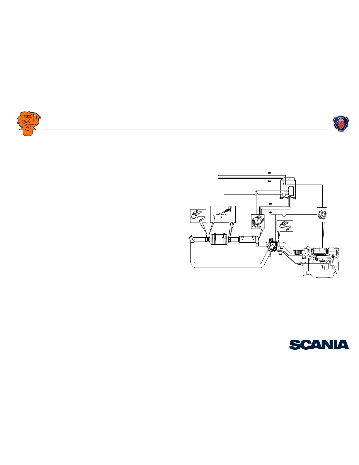
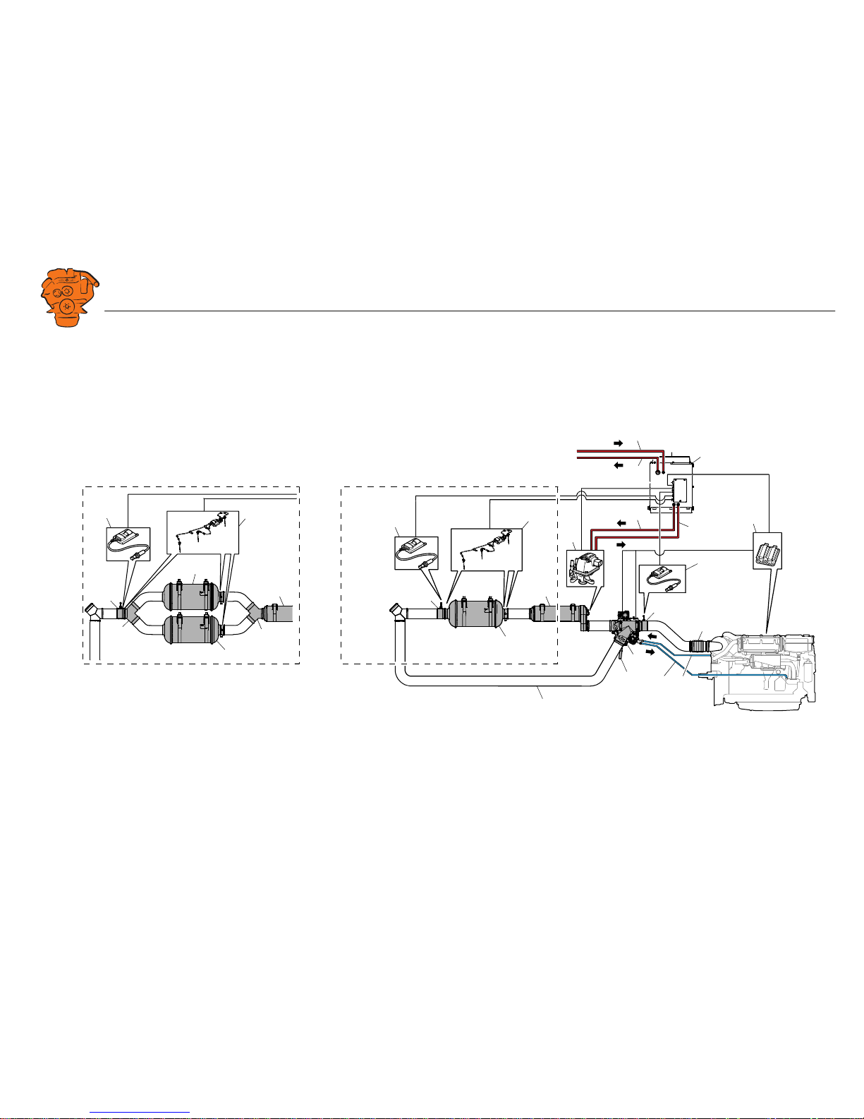
System overview
AB
368 025
1
2
4
3
5
6
7
8
10
9
11
12
13
14
1515
16
16
17
17
17
18
7
7
18
20
20
19
A: DI16.
B: DI13.
Page 5

INSTALLATION
MANUAL
© Scania CV AB 2016, Sweden
System overview
02:07 Issue 1.0 en-GB 5
Component Standard Option Fitted by fitter
1. Pressure pipe for reductant from the main tank - - x
2. Return pipe for reductant to the main tank - - x
3. Reductant tank (buffer tank) x - x
4. Pressure pipe for reductant from the buffer tank - - x
5. Return pipe for reductant to buffer tank - - x
6. Engine control unit x- -
7. NOx sensor (x 2) x- x
8. Exhaust bellows -xx
9. Coolant line from the engine to the exhaust control valve actuator - - x
10. Coolant return --x
11. Pipe section with outlet for NOx sensor T131 x - x
12. Exhaust routing valve with 2 actuators x - x
13. Handle to bypass the SCR system x - -
14. Reductant doser x- -
15. Evaporator x- x
16. Exhaust temperature sensor (x 3) x - x
17. SCR catalytic converter with outlets for 2 exhaust gas temperature sensors x - x
18. Pipe section with outlet for NOx sensor T115 and 1 exhaust gas temperature sensor x - x
19. Bypass pipe --x
20. Branch pipe (DI16 only) x - x
Page 6

INSTALLATION
MANUAL
© Scania CV AB 2016, Sweden
Exhaust pipe
02:07 Issue 1.0 en-GB 6
Exhaust pipe
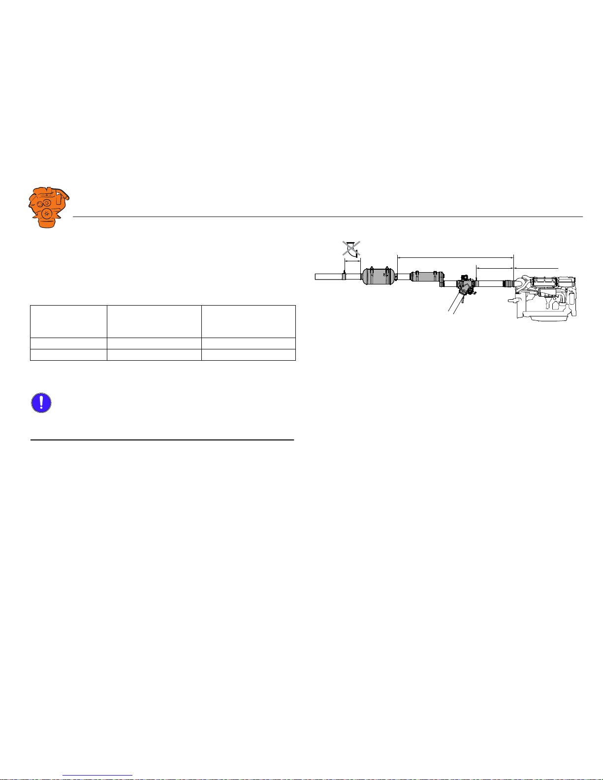
Pipe lengths
From To Max/min pipe length (mm)
A Turbocharger Pipe section for NOx sensor Max 1,500
B Turbocharger Evaporator intake Max 2,000
C Exhaust routing valve outlet Evaporator intake Max 500
D
1
1. DI16 only.
Evaporator outlet Branch pipe Min 300
E Evaporator outlet SCR catalytic converter inlet Max 1,500
F SCR catalytic converter outlet Pipe section for NOx sensor and exhaust temperature sensor Max 400
G Pipe section for NOx sensor and exhaust temperature sensor Exhaust outlet Min 500
12
A
B
C
E
F
DG G
E
F
368 800
1. DI16.
2. DI13.
Page 7
INSTALLATION
MANUAL
© Scania CV AB 2016, Sweden
Exhaust pipe
02:07 Issue 1.0 en-GB 7
Exhaust pipe bends
The sum of the exhaust pipe bends between the turbocharger outlet and NOx sensor
upstream of the exhaust routing valve must not exceed 270°.
The sum of the exhaust pipe bends between the turbocharger outlet and SCR catalytic
converter inlet must not exceed 540°. Example:
The radius of the exhaust pipe bends must be at least 1.5 x pipe diameter, based on a
pipe diameter of 127 mm (5 inches).
IMPORTANT!
No exhaust pipe bends may be installed between the SCR catalytic converter outlet
and the NOx sensor downstream of the SCR catalytic converter.
Max. angle before
Number of 90° exhaust
pipe bends
Number of 45° exhaust
pipe bends
SCR catalytic converter
540° 4 off 4 off
540° 6 off 0 off
379 171
Max 540°
Max 270°
Max. number of exhaust pipe bends in the SCR system.
Page 8
INSTALLATION
MANUAL
© Scania CV AB 2016, Sweden
Exhaust pipe
02:07 Issue 1.0 en-GB 8
Pipe material
The exhaust pipe between the evaporator and the SCR catalytic converter must be
made from stainless metal type 1.4301 or 1.4509, US grade 316L or equivalent. Scania also recommends that this material is used for other exhaust pipes downstream of
the SCR catalytic converter. Other instructions on exhaust system shape and fitting
are available in 02:04 Exhaust system.
Other requirements
IMPORTANT!
There should always be a flexible connection between the exhaust system and the engine which absorbs the movement of the engine and changes in length in the exhaust
system due to temperature changes. Also see 02:04 Exhaust system.
The brackets for exhaust routing valve, bypass pipe, evaporator and SCR catalytic
converter must be able to bear the weight of the component. The weight of the components must not load the exhaust bellows or turbocharger.
Tighten the V-clamps in the SCR system after the engine has warmed up to working
temperature for the first time. Carry out the retightening when the engine has cooled
down again. Tightening torque 20 Nm.
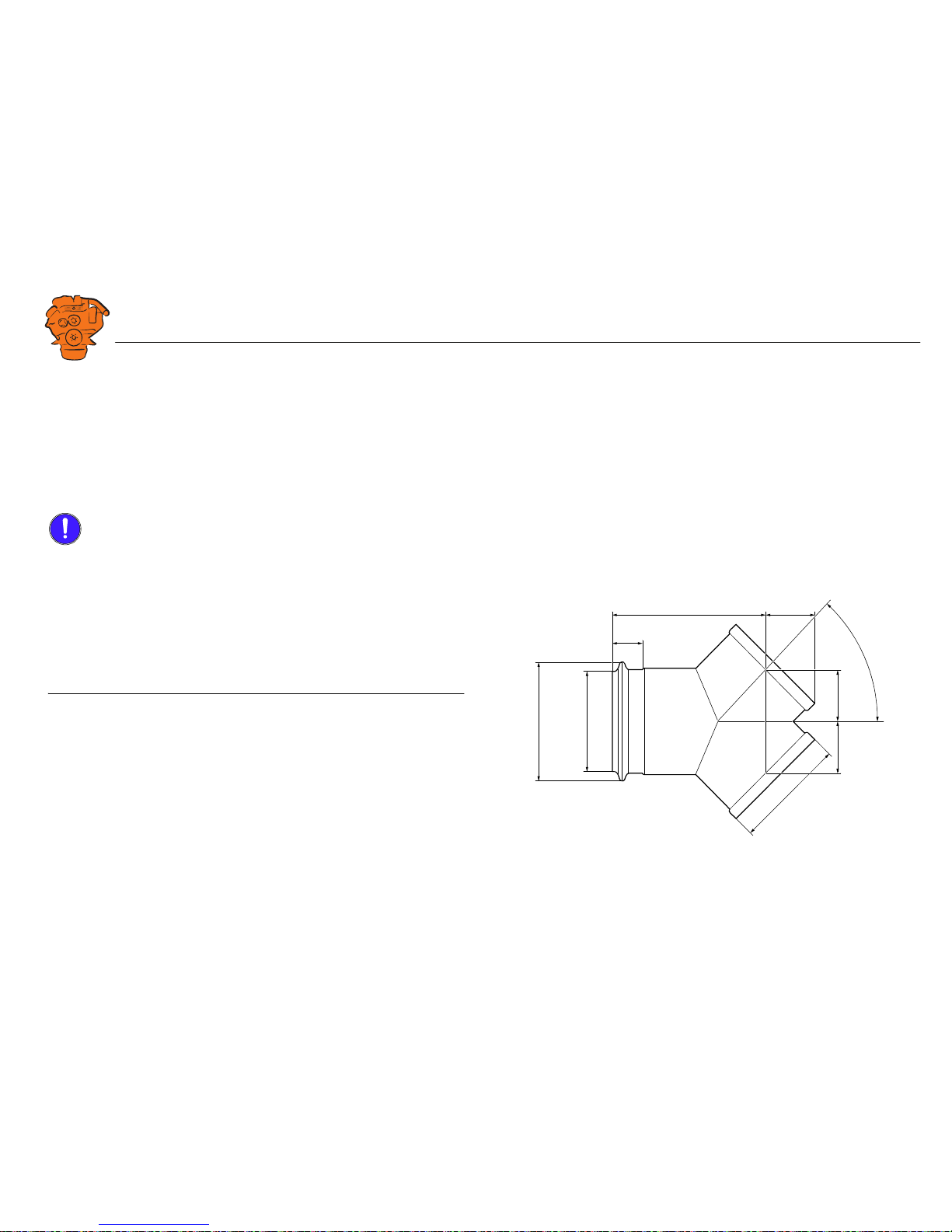
Branch pipe
The image shows the dimensions of the branch pipe used to connect the SCR catalytic converters to DI16.
366 031
2 x
2 x
45°
63,5
40
194
55
Ø122Ø144
Ø131 x 2
Page 9

INSTALLATION
MANUAL
© Scania CV AB 2016, Sweden
Main tank for reductant and reductant pipes
02:07 Issue 1.0 en-GB 9
Main tank for reductant and reductant
pipes
Example of installation
1. Evaporator.
2. Reductant doser.
3. Pressure pipe for reductant from the buffer tank.
4. Return pipe for reductant to buffer tank.
5. Buffer tank.
6. Pressure pipe for reductant from the main tank.
7. Return pipe for reductant to main tank.
8. Feed pump.
9. Prefilter.
10. Main tank for reductant.
11. Filling.
12. Overfill protection.
13. Level gauge.
14. Inspection hatch.
15. Ventilating valve.
16. Draining tap.
17. Baffle plate.
A = Max. height 2 metres from the pressure pipe connection on the buffer tank to the
reductant doser, max. length 16 metres.
1
5
10
16
2
15
6
98
7
14
17
11
13
12
3
4
380 406
A
Example of installation of the main tank for reductant and reductant pipes
Page 10

INSTALLATION
MANUAL
© Scania CV AB 2016, Sweden
Main tank for reductant and reductant pipes
02:07 Issue 1.0 en-GB 10
Materials for pipes and main tank
The main reductant tank, the reductant pipes and all couplings must be made of urearesistant material, such as stainless steel X5CrNi 18-10 in accordance with SS-EN
10088-2 or similar. Follow classification society requirements. If the material is
welded, its anti-corrosive qualities must be retained.
Dimension the reductant pipes according to the dimensions of the connections on the
buffer tank, as indicated in the Connecting the reductant tank
section.
Main tank
• Dimension the main tank so that there is sufficient reductant for the specific use
and area. Reductant consumption is approx. 9% of fuel consumption.
• The tank must be fitted with internal baffle plate to prevent the reductant from being thrown about at sea.
• The tank must have a drain tap.
• There must be ventilation or bleed line from the upper part of the tank to the outside of the hull. It should be designed so that water cannot enter and so that reductant cannot run out when the ship is leaning heavily.
• The tank must be fitted with inspection hatches so that it can be inspected and
cleaned inside.
• The pipe fitting should be at a sufficient distance from the bottom of the tank, so
as not to suck up deposits gathered at the bottom.
Main tank to buffer tank
• The pipes to the buffer tank should be as short as possible and should be mounted
in such a way that they cannot be exposed to mechanical damage.
• There must be a return pipe from the buffer tank to the main tank so that any surplus fluid runs back to the main tank.
Page 11

INSTALLATION
MANUAL
© Scania CV AB 2016, Sweden
Main tank for reductant and reductant pipes
02:07 Issue 1.0 en-GB 11
• There must be a prefilter with a filtration rating of 30-50 micrometres.
• There must be a fuel pump with a flow capacity of between 0.4 and 5 litres/minute.
Buffer tank to the evaporator
• The maximum length of the pipes between the buffer tank and evaporator reductant doser is 16 metres.
• The reductant doser should be installed level with or higher than the top of the
buffer tank. Otherwise there is a risk of a siphoning effect when the system is
switched off, leading to components breaking.
• The reductant doser can be installed a maximum of 2 metres above the pressure
pipe connection on the buffer tank.
Page 12

INSTALLATION
MANUAL
© Scania CV AB 2016, Sweden
Reductant tank (buffer tank)
02:07 Issue 1.0 en-GB 12
Reductant tank (buffer tank)
In the reductant tank, the reductant pump and SCR control unit are in front of an inspection hatch on the right-hand side of the tank.
Empty, the reductant tank weighs approx. 25 kg.
• Total volume: 30 litres.
• Filling volume: 16 litres.
Position
Do not position the reductant tank in a twisted or non-vertical position. Place the reductant tank so that the return pipe connection (1) is above the main tank, so that the
reductant can run back into the main tank. It does not matter how the reductant tank
is fitted in relation to the level of the engine.
Position the reductant tank so that the reductant cannot freeze. If the reductant freezes, the tank must be drained and cleaned. See the Workshop Manual.
Do not position the reductant tank near exhaust systems or heat sources. The reductant must not be heated to more than 55°C.
366 027
465,5
248
66
102,5
70
80,2
60
40
26
36
54
277
75
25,2
17
30
249
40
170,2
25
24,5
1
366 266
Page 13

INSTALLATION
MANUAL
© Scania CV AB 2016, Sweden
Reductant tank (buffer tank)
02:07 Issue 1.0 en-GB 13
Clearances
When the reductant tank is installed, the clearances below should be observed so that
the reductant tank can be maintained and repaired in a simple way.
Mounting
The reductant tank should be fitted with 3 brackets with 5 x 14 mm holes in each
bracket. The bottom brackets are shown in the picture to the right. The upper rear
bracket has the same dimensions and is shown under the heading Reductant tank
(buffer tank).
Use at least 2 of the brackets and 2 of the holes in each bracket when mounting. In
order to be able to remove the reductant tank for maintenance and repair, the brackets
must not be welded.
mm Purpose
A 235 To access the drain plug.
B 555 To lift out the reductant pick-up unit.
C 560 To open the inspection hatch to renew the reductant filter
and access the reductant pump and SCR control unit.
D 220 To undo the reductant pump screws.
E 225 To connect the reductant pipes and connectors.
366 029
B
C D
E
A
366 028
358
4 x
97,25
Ø 14
Page 14

INSTALLATION
MANUAL
© Scania CV AB 2016, Sweden
Reductant tank (buffer tank)
02:07 Issue 1.0 en-GB 14
Connecting the reductant tank
Description Connection
1. Pressure pipe for reductant from the
main tank
Nipple, Ø 8 mm, 24° internal conical thread in accordance with
DIN 3861
2. Return pipe for reductant to the main
tank
Nipple, Ø 22 mm, 24° internal conical thread in accordance with
DIN 3861
3. Voltage supply from engine. CAN connection
C7
4. Reductant doser C316
5. NOx sensor upstream of the exhaust
routing valve
C4051
6. NOx sensor downstream of the SCR
catalytic converter
C4011
7. Exhaust gas temperature sensor C4092
8. Reductant pressure pipe Pipe with ferrule,
to reductant doser Ø 8 mm
9. Reductant return pipe Pipe with ferrule,
to reductant pump Ø 10 mm
10 Drain plug 3/4" BSP
377 167
10
2
3
4
1
5
98
7
6
Page 15

INSTALLATION
MANUAL
© Scania CV AB 2016, Sweden
Exhaust routing valve
02:07 Issue 1.0 en-GB 15
Exhaust routing valve
Position
The exhaust routing valve may be installed horizontally or vertically. However, it
must not be mounted on the engine.
As the exhaust routing valve actuator may be damaged if the temperature is too high,
the space around the exhaust routing valve must be well-ventilated, and the accompanying insulation must be used. In addition, the actuators must be cooled by connecting a coolant circuit. See Connection of coolant
.
The exhaust routing valve weighs approximately 24 kg.
366 267
202
60°
234
115
85
405
146
39
244
179
30
26
24
Page 16

INSTALLATION
MANUAL
© Scania CV AB 2016, Sweden
Exhaust routing valve
02:07 Issue 1.0 en-GB 16
Mounting
The exhaust routing valve should be fitted with a bracket with 11 M10 holes. Use at
least 4 of the holes when mounting. The bracket must not be welded because the two
actuators may get damaged. In addition, it must be possible to remove the exhaust
routing valve in order to carry out repairs to it.
366 030
135
162
26
62
15
82
74
22
31
20
95
95
120
30
95
12
25
160
25
33
40
20
30 40
140
°
Exhaust routing valve bracket.
Page 17

INSTALLATION
MANUAL
© Scania CV AB 2016, Sweden
Exhaust routing valve
02:07 Issue 1.0 en-GB 17
Connection of coolant
This section shows how to connect a circulating coolant circuit between the engine
and the exhaust routing valve. However, it is also possible to connect an external
coolant circuit.
Note:
Do not use sea water to cool the exhaust routing valve.
Scania recommends using pipes, but it is also possible to use hose.
It does not matter which of the connections of the exhaust routing valve (3) are used
for coolant intake or coolant return.
The images show the coolant connections on DI13 and DI16:
1. Coolant out of the engine. M22x1.5.
2. Coolant return to the engine. DI13: M22x1.5. DI16: M26x1.5.
3. Coolant connection to exhaust routing valve. M22x1.5.
2
3
1
377 169
DI13.
2
1
1
377 170
DI16.
Page 18

INSTALLATION
MANUAL
© Scania CV AB 2016, Sweden
Exhaust routing valve
02:07 Issue 1.0 en-GB 18
Connecting the coolant pipe
If pipes are used for coolant connection, there must be at least one hose connection
on each pipe to and from the engine, which will absorb vibrations from the engine.
The pipe material must be refrigerant-resistant.
If pipe is to be used, the pre-assembled nipples on the exhaust routing valve must be
removed.
Hose connection
Use hose with an internal diameter of 16 mm to connect to the pre-assembled nipples
on the exhaust routing valve. The material must be EPDM-type or similar, and must
be able to withstand a working pressure of 2.4 bar. The material must be refrigerantresistant.
Note:
To ensure sufficient flow, hoses must not have any sharp bends and there must be no
spots where they are at risk of being pinched.
377 171
1
6
43
Nipples to connect the coolant hose to the exhaust routing valve.
Page 19

INSTALLATION
MANUAL
© Scania CV AB 2016, Sweden
Evaporator
02:07 Issue 1.0 en-GB 19
Evaporator
Position
The evaporator must be fitted in the direction of the exhaust gases as illustrated. It
may be installed horizontally or with the outlet pointing downwards. The intake can
be rotated 360°.
The space around the evaporator must be well-ventilated. The maximum permissible
ambient temperature is 115°C. The accompanying insulation must be used. The
evaporator weighs approx. 17 kg.
Mounting
The evaporator is supplied with two retaining straps with brackets. Attach the brackets with flange screw M12 or a common screw of a suitable length. Use an M12
flange nut if necessary.
Tightening torques
Flange bolt M12: 77 Nm. Regular screw M12: 70 Nm.
Retaining strap: 40 Nm.
377 172
203
80
343
210 300 174 112
400
37
22,5
Ø 13
122
122
Page 20

INSTALLATION
MANUAL
© Scania CV AB 2016, Sweden
Evaporator
02:07 Issue 1.0 en-GB 20
Connection of reductant doser
The evaporator is supplied with two hoses which are connected to the reductant doser. The hoses must be used as they absorb vibrations from the pipes to and from the
reductant tank. The maximum bend radius for the hoses is 50 mm.
Connection Note
1. Electrical cable to reductant tank. V117
2. Reductant return pipe. Ø 10 mm
3. Reductant pressure pipe. Ø 8 mm
1
3
2
377 173
Page 21

INSTALLATION
MANUAL
© Scania CV AB 2016, Sweden
SCR catalytic converter
02:07 Issue 1.0 en-GB 21
SCR catalytic converter
Position
The SCR catalytic converter must be fitted in the direction of the exhaust gases as
illustrated. It may be installed horizontally or with the outlet pointing upwards.
For DI16, two SCR catalytic converters are used. They may be longitudinally displaced. Longitudinal displacement is limited by the length of the electrical cables of
the exhaust gas temperature sensors. See the Exhaust gas temperature sensor
section.
The SCR catalytic converter weighs approx. 30 kg. It can be ordered with or without
insulation.
Mounting
The SCR catalytic converter is supplied with two retaining straps with brackets. Attach the brackets with M10 flange screws.
Tightening torques
M10 42 Nm
Retaining strap 39 Nm
366 032
Ø 10
270 300 285
369
36
130
Page 22

INSTALLATION
MANUAL
© Scania CV AB 2016, Sweden
NOx sensor
02:07 Issue 1.0 en-GB 22
NOx sensor
The SCR system comes with two NOx sensors, which have their own control unit.
The sensor control units are connected to the SCR control unit in the reductant tank.
See Connecting the reductant tank
. The control unit should be shielded from radiated
heat and knocks. The electrical cables between the sensors and the control units must
not be spliced.
Fitting
Fit NOx sensor T131 to one of the accompanying pipe sections, which should be positioned upstream of the exhaust routing valve. The pipe section has only one outlet
for this NOx sensor.
The other pipe section must be fitted on the outlet side of the SCR catalytic converter.
The pipe section has an outlet for NOx sensor T115 and also an outlet for an exhaust
gas temperature sensor. See the following section.
Electrical cable length
(mm)
Tightening torque (Nm)
910 50 ±10
368 023
148
108
65
3
A
9
7
NOx sensor (x 2).
T131: A = 42 mm.
T115: A = 38 mm.
21
366 033
100100
1. Outlet for NOx sensor T131 in pipe section upstream of exhaust routing valve.
2. Outlet for NOx sensor T115 in pipe section downstream of SCR catalytic convert-
er.
Page 23

INSTALLATION
MANUAL
© Scania CV AB 2016, Sweden
Exhaust gas temperature sensor
02:07 Issue 1.0 en-GB 23
IMPORTANT!
The NOx sensors and control units must not be painted. The NOx sensors must be
fitted so that there is no risk of them coming into contact with water. The maximum
installation angle is 90°.
Exhaust gas temperature sensor
The SCR system comes with three exhaust gas temperature sensors, which share a
control unit. The sensor control unit is connected to the SCR control unit in the reductant tank. See Connecting the reductant tank
. The control units should be shielded
from radiated heat and knocks. The electrical cables between the sensors and the control unit must not be spliced. The connection between the sensor and the electrical
cables must not be insulated, as it may be damaged if it is exposed to temperatures
above 200°C.
Colour
code
Electrical cable
length (mm)
Max. rotation (°)
1
1. Max. rotation means how much the electrical cable can be twisted around its own axis.
Tightening torque
(Nm)
1 Blue 980 180
35-402 Yellow 1,570 270
3 White 1,220 270
max 90
o
max 90
o
0
o
352 613
Maximum installation angle for NOx sensors.
368 024
1
2
3
90
109
52,5
81
28
6
Exhaust gas temperature sensor.
Page 24

INSTALLATION
MANUAL
© Scania CV AB 2016, Sweden
Exhaust gas temperature sensor
02:07 Issue 1.0 en-GB 24
Fitting
The two shorter exhaust temperature sensors (blue and white in colour) should be fitted to the outlets of the inlet side of the SCR catalytic converter (1). On DI16, one
temperature sensor should be fitted to each SCR catalytic converter and the other outlet plugged.
The longer exhaust temperature sensor (yellow in colour) should be fitted to the pipe
section on the outlet side of the SCR catalytic converter (1).
1
368 022
1. Outlet for exhaust temperature sensor (blue and white) on the inlet side of the
SCR catalytic converter.
380 185
1
100
1. Outlet for exhaust temperature sensor (yellow) in the pipe section downstream of
the SCR catalytic converter.
 Loading...