

Page 1
Operator’s Manual
DI12, DC12
EMS with S6/PDE
Industrial engine
opm_d12ind_en-GB01 1 920 785
IMPORTANT INFORMATION
When work is being carried out on the engine such as adjusting drive belts, changing oil or
adjusting the clutch, it is important not to start the engine. The engine may be damaged and
there is
A SERIOUS RISK OF INJURY
For this reason, always secure the starting device or disconnect a battery cable before working on
the engine.
This is especially important if the engine has a remote starter or automatic starting.
This warning symbol and text is reproduced beside those maintenance points where the risk of
injury is particularly great.
!
COMMISSIONING REPORT - WARRANTY
When the commissioning report has been filled in and sent to Scania, you have a 1-year warranty from the date
of commissioning.
Also fill in the particulars below as this can make things easier if you need to contact for example a service
workshop.
Engine number
Date of commissioning
User’s name and address
Signature
Engine type
Variant
Engine type and variant are indicated on the engine type plate
Page 2

2 © Scania CV 2009
Foreword
This Operator’s Manual describes the handling and maintenance of Scania
DC12 and DI12 Industrial Engines with EMS S6/PDE injection systems.
The engines are of direct-injection, liquid-cooled, four-stroke, 6-cylinder inline diesel type. These engines have turbochargers and charge air coolers; see
page 14.
Common applications are as power units in construction machines, generator
sets, earth-moving, railway and forestry machines as well as in irrigation
systems.
The engines can have different output and speed settings.
The normal output setting of the engine (performance code) is indicated on
the type plate, see page 14.
Note: Only standard components are described in the Operator’s
Manual. Please see the manufacturer’s instructions regarding
special equipment.
In order to obtain the best value and service life from your engine, there are
several points you should bear in mind:
- Read the manual before starting to use the engine. Even though you may
have experience of Scania engines you may find new information in this
Operator’s Manual.
- Follow the maintenance instructions. Good working order and service
life are ensured if maintenance is carried out according to the
instructions.
- In particular, read the safety information starting on page 6.
- Get to know your engine so that you know what it can do and how it
works.
- If necessary, contact an authorised Scania workshop. They have special
tools, genuine Scania parts and staff with training and practical
experience of Scania engines.
Note: Always use genuine Scania parts during service and repair so as
to keep your engine in the best possible working order.
The information in this manual was correct at the time of going to press.
However, we reserve the right to make alterations without prior notice.
During the warranty period,
only genuine Scania parts may
be used during service and
repair; otherwise the warranty
will be invalidated.
Important
!
Page 3

© Scania CV 2009 3
Contents
Preface. . . . . . . . . . . . . . . . . . . . . . . . . . . . . . . . 2
Environmental responsibility .........................4
Certified engines ............................................5
Scania industrial and marine engine warranty
for industrial engines.......................................6
Safety information ........................................10
Safety precautions before running . . . . . . . . .11
Safety precautions for materials handling . . . .12
Safety precautions for care and maintenance .12
Type designations . . . . . . . . . . . . . . . . . . . . . 14
Engine management system, EMS . . . . . . . 16
Troubleshooting using flash codes for the
EMS control unit . . . . . . . . . . . . . . . . . . . . . . .20
Overview of flash codes for the EMS
control unit . . . . . . . . . . . . . . . . . . . . . . . . . . .21
Troubleshooting using flash codes for the
EMS coordinator . . . . . . . . . . . . . . . . . . . . . . .22
Overview of flash codes for the EMS
coordinator . . . . . . . . . . . . . . . . . . . . . . . . . . .23
Starting and driving . . . . . . . . . . . . . . . . . . . 24
First start .......................................................24
Checks before running .................................25
Starting the engine ........................................25
Starting at low temperatures . . . . . . . . . . . . . .26
Running ........................................................26
Engine speed . . . . . . . . . . . . . . . . . . . . . . . . . .26
Limp home mode . . . . . . . . . . . . . . . . . . . . . . .27
Coolant temperature . . . . . . . . . . . . . . . . . . . .27
Oil pressure . . . . . . . . . . . . . . . . . . . . . . . . . . .28
Stopping the engine ......................................29
Checks after running ....................................29
Maintenance . . . . . . . . . . . . . . . . . . . . . . . . . 30
Engines with few hours of operation ...........30
Maintenance schedule .................................. 31
Lubricating oil system . . . . . . . . . . . . . . . . . 32
Oil grade .......................................................32
Oil analysis . . . . . . . . . . . . . . . . . . . . . . . . . . .32
Checking the oil level ...................................33
Checking oil level during operation . . . . . . . . 33
Oil change ....................................................33
Maximum angles of inclination during
operation . . . . . . . . . . . . . . . . . . . . . . . . . . . . .33
Cleaning the oil filter unit ............................ 34
Renewing the oil filter .................................. 36
Cooling system . . . . . . . . . . . . . . . . . . . . . . . . 36
Checking coolant level .................................36
Checking coolant ..........................................37
Checking the corrosion protection . . . . . . . . . 39
Changing the coolant . . . . . . . . . . . . . . . . . . .39
Cleaning the cooling system .........................40
Internal cleaning . . . . . . . . . . . . . . . . . . . . . . .41
Air cleaner . . . . . . . . . . . . . . . . . . . . . . . . . . . 42
Test reading of vacuum indicator .................42
Cleaning the air cleaner coarse cleaner ........42
Cleaning or changing filter element .............42
Renewing the safety cartridge ......................43
Fuel system . . . . . . . . . . . . . . . . . . . . . . . . . . . 44
Checking the fuel level .................................44
Changing the fuel filter .................................44
Electrical system . . . . . . . . . . . . . . . . . . . . . . 46
Checking the electrolyte level in batteries ...46
Checking the state of charge in batteries ......46
Cleaning batteries .........................................46
Renewing the battery ....................................47
Checking coolant level monitor ...................47
Miscellaneous . . . . . . . . . . . . . . . . . . . . . . . . . 48
Checking the drive belt .................................48
Look for leakage, rectify as necessary .........49
Check and adjust valve clearance .................50
Checking and adjusting the unit injector
rocker arms ...................................................52
Renewing (or cleaning) the closed
crankcase ventilation valve ..........................56
Preparing the engine for storage . . . . . . . . . 57
Preservative fuel . . . . . . . . . . . . . . . . . . . . . . .57
Preservative oil . . . . . . . . . . . . . . . . . . . . . . . .58
Preparation for storage . . . . . . . . . . . . . . . . . .58
Batteries . . . . . . . . . . . . . . . . . . . . . . . . . . . . .59
Storage . . . . . . . . . . . . . . . . . . . . . . . . . . . . . .59
Taking out of storage . . . . . . . . . . . . . . . . . . .59
Technical data . . . . . . . . . . . . . . . . . . . . . . . . 60
Fuel ...............................................................62
Alphabetical index . . . . . . . . . . . . . . . . . . . . . 64
Scania Assistance . . . . . . . . . . . . . . . . . . . . . . 65
Page 4
4 © Scania CV 2009
Environmental responsibility
Scania has always been very much at the leading edge when it comes to
developing and producing engines which are as environmentally friendly as
possible.
Major progress has been made on reducing harmful exhaust emissions as
required to be able to meet the stringent environmental standards stipulated
on almost all markets.
At the same time, we have been able to maintain high quality in terms of
performance and operating economy for Scania Industrial and Marine
Engines.
To preserve these qualities throughout the entire service life of the engine, it
is important for the operator/owner to follow the instructions on running,
maintenance and the choice of fuel and oil as outlined in the manual.
Other efforts to preserve the environment we all share are possible by
ensuring that the person carrying out servicing and maintenance always
makes sure that environmentally hazardous waste after servicing and repairs
(oil, fuel, coolant, filters, batteries, etc.) is dealt with and disposed of in
accordance with applicable environmental standards.
On a number of pages, this Operator’s Manual contains specially highlighted
text with instructions to help protect our environment during certain servicing
and maintenance work.
See example
Use a container to avoid spillage
when bleeding and changing
components.
Help protect our
environment!
Page 5

© Scania CV 2009 5
Certified engines
Emissions-certified engines have been approved in accordance with a special
certification standard. The certified engines supplied by Scania meet the most
stringent emissions standards which apply on European (EU) and nonEuropean (USA) markets.
Scania guarantees that all the engines it supplies of a certified type are
equivalent to the engine approved for certification.
The engine comes with a special certification plate which indicates the
certification rules (standard) to which the engine has been approved. See
page 14.
The following is required for the certified engine to meet emissions standards
once it has been commissioned:
- Servicing and maintenance must be carried out in accordance with the
instructions in this manual.
- Only genuine Scania parts are to be used.
- Injection equipment is to be serviced by an authorised Scania workshop.
- The engine must not be modified with equipment not approved by
Scania.
- Seals may be broken and setting data edited only once approval has been
granted by Scania in Södertälje. Changes may be made by authorised
personnel only.
- Changes which affect the exhaust system and intake system must be
approved by Scania.
Otherwise, the instructions in the manual in respect of running, care and
maintenance of the engine shall apply. The safety precautions described over
the next four pages must also be observed.
Important! If servicing and maintenance are not carried out as
specified above, Scania can no longer guarantee that the
engine will comply with the certified design, nor can it take
responsibility for any damage that occurs.
Page 6

6 © Scania CV 2009
Scania industrial and marine
engine warranty for industrial
engines
Emission Control Systems Warranty
Important! Only applicable to engines used in the U.S.A.
Table of contents
General Warranty Provisions ......................... 6
Warranty Period ............................................. 7
Parts covered by the Warranty ....................... 7
General Warranty Limitations ....................... 8
Specific Warranty Exclusions ....................... 9
Customer Support ........................................... 9
Emission Control System Warranty
Statement
General warranty provisions
The emission control systems of your new Scania Industrial and Marine
("Scania") industrial diesel engine were designed, built and tested using
genuine parts, and were certified as being in conformity with federal emission
control regulations. Scania warrants to the original owner, and to each
subsequent owner, of a new Scania industrial diesel engine that the engine:
1. Was designed, built and equipped so as to conform at the time of sale
with all applicable regulations under Section 213 of the Clean Air Act
42 U.S.C. § 7547, and all applicable regulations under Chapter 1 and 2,
Part 5, Division 26 of Health and Safety Code, and;
2. Is free from defects in material and workmanship which would cause
such engine to fail to conform to applicable regulations for its warranty
period.
Page 7

© Scania CV 2009 7
Warranty Period
This warranty shall apply for one of the following periods, whichever occurs
first:
• 3,000 hours of operation, or
• Five years of use
The warranty period shall begin:
• "On the date the engine is delivered to the first retail purchaser, or
• "If the engine is placed in service for demonstration purposes prior to
sale at retail, on the date the engine is first placed in service.
Parts covered by the Warranty
The following is a list of parts considered to be part of the Emission Control
Systems covered by the Emission Warranty for Scania industrial engines
which were built to conform to federal emission control regulations:
1. Fuel injection system
2. Air intake system
• Intake manifold
• Turbocharger system
• Charge air cooler system
3. Exhaust manifold
4. Combustion chamber
• Piston
• Cylinder head
5. Components used in the above mentioned systems
Important! This list does not include all expendable maintenance parts.
Expendable emission related parts requiring scheduled
maintenance are warranted until their first scheduled
replacement point. See Specific Warranty Exclusions
below.
Page 8

8 © Scania CV 2009
General Warranty Limitations
To retain the dependability of the exhaust emission control originally built
into your Scania industrial diesel engine, it is essential that the engine is
installed according to Scania installation instructions and emission
certificates.
In addition, you are responsible for the performance of all scheduled
maintenance and necessary repairs on your new Scania industrial diesel
engine. Scania may deny a warranty claim if your failure to perform
maintenance resulted in the failure of the warranted part, listed under Parts
covered by the Warranty above.
Receipts covering the performance of regular maintenance should be retained
in the event questions arise concerning maintenance. The receipts should be
transferred to each subsequent owner of the engine with the emission
warranted engine.
The Warranty covers the cost of repair and replacement parts and services of
warranted components and systems performed by an authorized Scania
distributor or dealer using genuine Scania parts. You may elect to have
maintenance, replacement or repair of these components and systems
performed by any repair establishment or individual without invalidating the
Warranty.
The use of other than Scania replacement parts also does not invalidate the
warranty on other components unless such parts cause damage to warranted
parts. However, the cost of such services or parts will not be covered by the
Warranty.
WARNING!Use of replacement parts which are not of equivalent
quality may impair the effectiveness of emission control
systems. Accordingly, it is recommended that only Scania
repair or replacement parts be used for maintenance, repair
or replacement of emission control systems. If other than
Scania parts are used for maintenance, repair or
replacement, the owner should obtain assurance that such
parts are warranted by their manufacturer to be equivalent
to genuine Scania parts
Page 9

© Scania CV 2009 9
Specific Warranty Exclusions
This warranty does not cover:
1. Malfunctions in any part caused by any of the following: misuse, abuse,
improper adjustments, modifications, alteration, tampering,
disconnection, improper or inadequate maintenance, or use of fuels not
recommended for the engine as described in the Operator's Manual.
2. Engine installation, including cooling system, intake system and exhaust
system installation, that is not completed in accordance with the Scania
installation instructions and emissions certificate for this engine type.
3. Damage resulting from accidents, acts of nature or other events beyond
the control of Scania.
4. The replacement of expendable maintenance items such as filters, hoses,
belts, oil, thermostat, exhaust system and coolant made in connection
with scheduled maintenance services once these parts have been
replaced.
5. Replacement items which are not genuine Scania parts or not authorized
by Scania.
6. Inconvenience, loss of use of the engine or commercial loss.
7. Any engine on which the actual use cannot be accurately determined.
8. Any engine operating outside the United States.
Customer Support
In the event that you do not receive the warranty service to which you believe
you are entitled under the Warranty, or if you need additional support or
information concerning the Warranty, please contact:
Scania USA, Inc
Address: 121 Interpark Blvd, suite 601, 78216, San Antonio, Texas
Mailing address: 121 Interpark Blvd, suite 601, 78216, San Antonio,
Texas
Telephone: +1 210 403 0007
Fax: +1 210 403 0211
E-mail: contact@scaniausainc.com
Page 10
10 © Scania CV 2009
Safety information
General
This Operator’s Manual contains safety information which is important so as
to avoid both personal injury and damage to the product/other property. See
also page 1.
The text highlighted in text boxes on the right of a number of pages is
important for engine function and in order to avoid damage to the engine. If
these instructions are not followed, your warranty may be invalidated.
See example
Similar text may also appear in the text column, and in this instance it will be
marked
Note: or Important!.
The warning text found in text boxes on the right of a number of pages which
is marked with a warning triangle and starts with
WARNING is extremely
important and warns you of serious engine faults or incorrect handling which
may lead to injury.
See example
A list of the safety precautions to be followed when running and maintaining
Scania engines can be found on the next three pages. Similar text can often be
found at the relevant maintenance points, and here different levels of
importance are attached to such text in accordance with the above
description.
All points are marked
!, so as to indicate how important it is to read through
each point in this section.
For safety reasons, smoking is not allowed:
• In the vicinity of the engine and in the engine room
• When fuelling and close to the filling station
• When working on the fuel system
• In the vicinity of inflammable or explosive material (fuel, oils,
batteries, chemicals, etc.)
Block the starting device when
working on the engine.
If the engine starts accidentally,
there is a
SERIOUS RISK OF INJURY.
Only use genuine Scania fuel
filters.
Important
!
WARNING
!
Page 11

© Scania CV 2009 11
Safety precautions for running the engine
Daily inspection
Always visually inspect the engine and engine
compartment before starting the engine and once
you have stopped the engine after running.
This will enable you to easily detect fuel, oil or
coolant leaks, or any other abnormalities which may
require rectification.
Refuelling
There is a risk of fire and explosion when refuelling.
The engine must be stopped and smoking is not
allowed.
Do not overfill the tank due to a risk of expansion,
and close the filler cap properly.
Use only fuel recommended in the service
literature. Fuel of the wrong quality can cause the
engine to malfunction or stop by preventing the
injection pump and injectors from operating as they
should.
This can cause damage to the engine and, possibly,
injury.
Hazardous gases
Only start the engine in a well ventilated area. The
exhaust fumes contain carbon monoxide and nitric
oxides, which are toxic.
If it is run in a enclosed space, there should be an
effective device to extract exhaust gases and
crankcase gases.
Starter lock
If the control panel is not fitted with a key operated
switch, there should be a lock on the engine room to
prevent unauthorised starting of the engine.
Alternatively, a lockable on/off master switch or
battery master switch can be used.
Starter spray
Never use starting spray or similar as a starting aid.
This can cause an explosion in the intake manifold
and possible injury.
Running
The engine must not be run in environments where
there is a risk for explosion as all of the electrical or
mechanical components can generate sparks.
Approaching a running engine always poses a safety
risk. Parts of the body, clothes or dropped tools can
get caught in rotating parts such as the fan and cause
injury.
For personal safety all rotating parts and hot
surfaces must therefore be shielded as much as
possible.
Page 12

12 © Scania CV 2009
Safety precautions for handling
materials
Fuel and lubricating oil
All fuels and lubricants and many chemicals are
flammable. Always follow the instructions on the
relevant packaging.
All work on the fuel system must be done with the
engine cold. Fuel leaks and spillage on hot surfaces
can cause fire.
Store soaked rags and other flammable materials
safely so as to avoid spontaneous combustion.
Batteries
The batteries contain and emit oxyhydrogen gas,
particularly during charging, and this gas is
flammable and highly explosive. There must be no
smoking, naked flames or sparks near the batteries
or the battery compartment.
Incorrect connection of a battery cable or jump lead
can cause a spark, which in turn can cause the
battery to explode.
Chemicals
Most chemicals such as glycol, corrosion inhibitors,
preservative oils, degreasing agents, etc. are
hazardous to health. Always follow the safety
precautions on the relevant packaging.
Some chemicals, such as preservative oil, are also
flammable.
Store chemicals and other materials which are
hazardous to health in approved containers, marking
them clearly and storing them where they are
inaccessible to unauthorised persons. Always hand
in leftover or used chemicals to an authorised waste
disposal contractor.
Safety precautions for care and
maintenance
Stop the engine
Always stop the engine before maintenance and
servicing unless stated otherwise.
Prevent unwanted starting by taking out the ignition
key where applicable and disconnecting the power
using the master switch or battery master switch and
locking them. Also put up a warning sign
somewhere appropriate, indicating that work is in
progress on the engine.
Working with a running engine always poses a
safety risk. Parts of the body, clothes or dropped
tools can get caught in rotating parts and cause
injury.
Hot surfaces and fluids
There is always a risk of sustaining burns when an
engine is hot. Therefore, take care not to come into
contact with manifolds, the turbocharger, the sump,
hot coolant and oil in pipes and hoses.
Lifting the engine
The engine lifting eyes must be used when lifting
the engine. Check first that your lifting devices are
in good condition and of the correct size to lift the
weight.
Extra equipment on the engine can alter the centre of
gravity, which is why you may need additional
lifting devices to balance the engine correctly and
lift it safely.
Never work underneath a suspended engine!
Batteries
The batteries contain a highly corrosive electrolyte
(sulphuric acid). Take care to protect your eyes, skin
and clothes when charging or handling batteries.
Wear protective gloves and goggles.
If the acid splashes on your skin, wash it off with
soap and copious amounts of water. If acid splashes
in your eyes, flush them immediately with copious
amounts of water and contact a doctor.
Dispose of used batteries through an authorised
waste disposal contractor.
Page 13

© Scania CV 2009 13
Electrical system
The engine must be stopped and the power
disconnected using the master switch or battery
master switch before working on the electrical
system.
External power supplies to extra equipment on the
engine must also be disconnected.
Electric welding
When carrying out welding work close to and on the
engine, remove the battery leads and the cables to
the alternator. Also remove the multi-pin connector
to the control unit.
Connect the weld clamp to the component to be
welded and close to the welding point, never to the
engine or in such a manner that the current can pass
over to a mounting.
When you have finished welding, connect the cables
to the alternator and control unit before connecting
the batteries.
Lubrication system
Hot oil can cause burns and skin irritation.
Therefore, avoid skin contact with hot oil.
Make sure that there is no pressure in the lubricating
system before starting work on it. Never start or run
the engine with the oil filler cap removed, as this
may cause oil to be thrown out.
Dispose of used oil through an authorised waste
disposal contractor.
Cooling system
Never open the coolant filler cap if the engine is hot.
Hot coolant or steam may spray out and cause burns.
If you have to open or remove a cooling system
component when the engine is hot, open the cap
very carefully and slowly to relieve the system
pressure before removing the cap. Wear gloves as
the coolant is still very hot.
Dispose of used coolant through an authorised
waste disposal contractor.
Fuel system
Always wear gloves when looking for leaks or
carrying out any other work on the fuel system. Also
wear protective goggles when testing injectors.
Fuel escaping at high pressure can penetrate tissues
and cause serious injury.
Never use non-genuine parts in the fuel and
electrical systems as genuine parts are designed and
manufactured to minimise the risk of fire and
explosion.
Before starting
Fit all removed shields before starting the engine
again. Check that you have not left any tools or other
objects on the engine.
Never start the engine without the air filter fitted.
There is a risk of objects being sucked into the
compressor impeller or of injury if you come into
contact with it.
Page 14
14 © Scania CV 2009
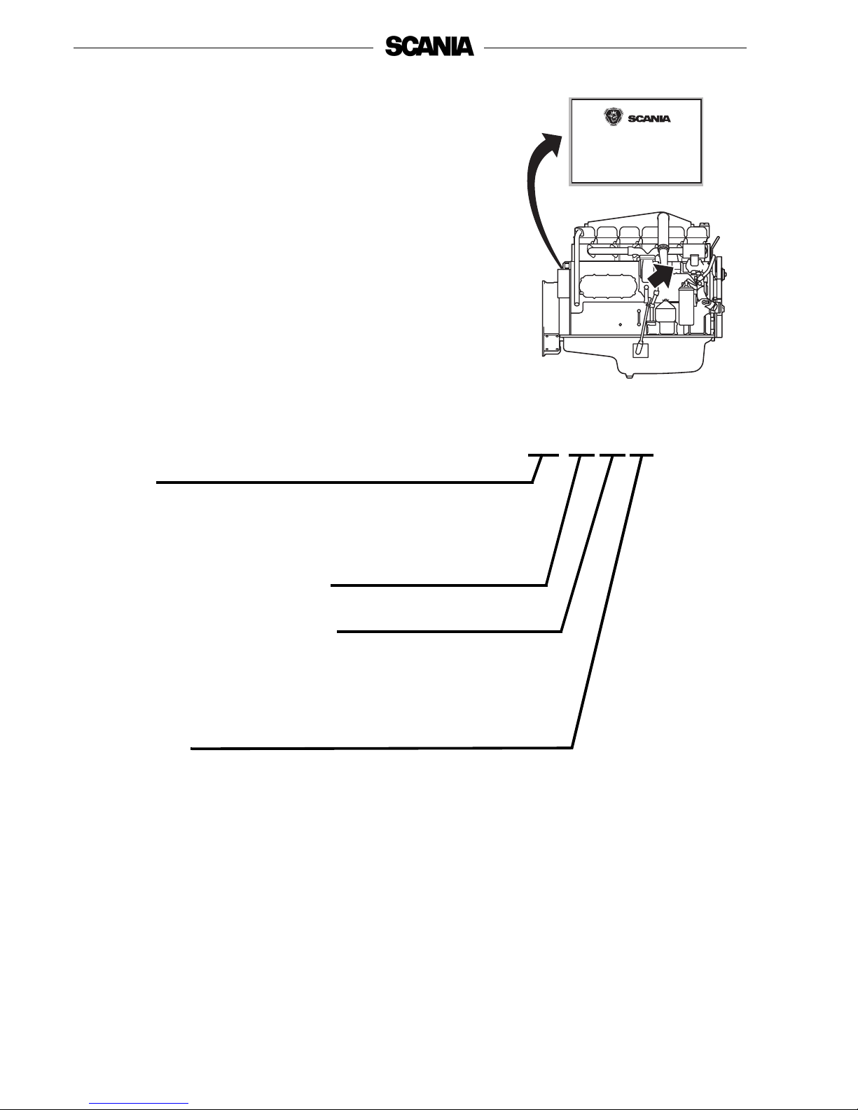
Type designations
The engine type designation indicates engine type, size and applications in
code form.
The type designation and engine serial number are specified on a type plate
affixed to the right-hand side of the flywheel housing. The engine number is
also stamped on the right-hand side of the cylinder block. See the arrow in
illustration.
Version
DC Supercharged diesel engine with air-cooled charge air cooler
DI Supercharged diesel engine with liquid-cooled charge air cooler
Displacement in whole dm
3
Performance and certificate
Indicates, together with the application code, the normal gross engine
output. The actual output setting of the engine is indicated on the engine
card.
Application
A For general industrial use
Made by
Type
Engine No
Output.
Output
kWkWrpm.
rpm.
DI12 54A
6521399
2200331
308 664
DI 12 54 A
Page 15
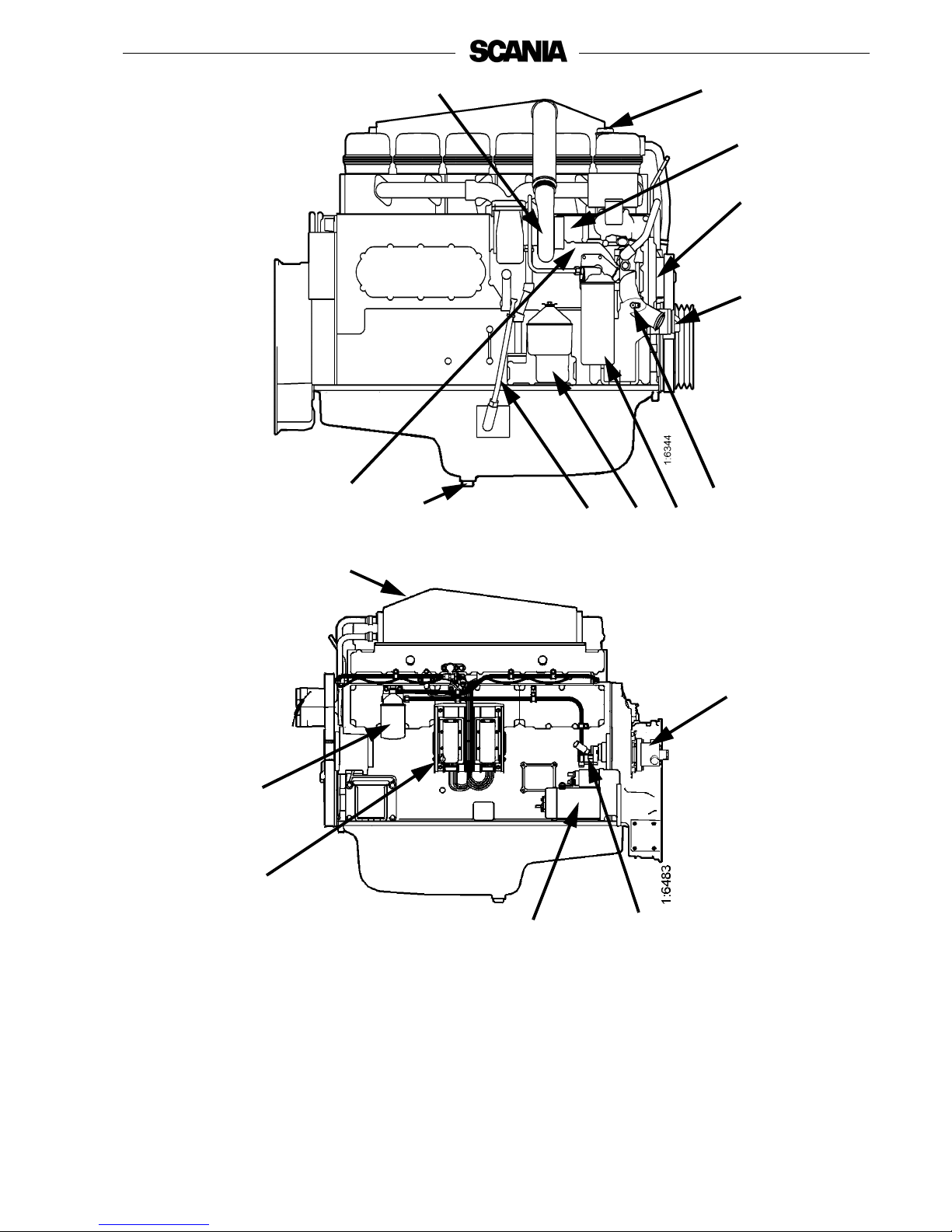
© Scania CV 2009 15
10
8
1, 2
4
3
12
9
11
5
7
6
15
17
13
18
16
14
1. Type plate
2. Engine number, stamped
into the cylinder block
3. Coolant pump
4. Automatic belt tensioner
5. Draining, coolant
6. Oil filter
7. Oil filter unit
8. Oil dipstick
9. Draining, engine oil
10. Oil cooler
11. Turbocharger
12. Oil filler
13. Hydraulic pump
14. Fuel pump with hand pump
15. Starter motor
16. S6 control unit
17. Fuel filter
18. Charge air cooler
The illustrations show a normal version of a DI12-engine.
Your engine may have different equipment from that illustrated.
Page 16

16 © Scania CV 2009
EMS engine management
system
This engine has an electronic management system, EMS (Engine
Management System) with unit injectors (PDE) which provide each cylinder
with the right amount of fuel at the right time in all operating situations.
The EMS system consists of a control unit (S6) and sensors for speed, charge
air temperature and pressure, coolant temperature, oil pressure, accelerator
pedal/throttle actuation which constantly emit signals to the control unit.
With the aid of this input data and the programmed control software, the
correct fuel amount and correct injection time are calculated for each unit
injector under the specific operating conditions.
The EMS system sensors can also be used to emit signals to the instruments
in the instrument panel.
The control unit constantly checks the sensors to make sure they are
operational.
The control unit contains monitoring functions to protect the engine in the
event of a fault which would otherwise damage it. In the event of a fault, for
example alarm level for low oil pressure or high coolant temperature, the S6
control unit sends a CAN message to a coordinator.
The main task of the coordinator is to pass on data by means of CAN
communication from the engine control unit to other control units and signals
to gauges and lamps in the instrument panel. The coordinator also has
monitoring functions.
Page 17

© Scania CV 2009 17
When the EMS control unit or the coordinator detects a fault, the diagnostics
lamp on the instrument panels(s) comes on, and it stays on as long as the fault
is active. At the same time, a fault code is generated which can be read off via
the coordinator on the diagnostics lamp in the form of a flash code when the
diagnostics switch is activated. A flash code may consist of a number of
different fault codes.
Diagnosis and troubleshooting using Scania EMS Display is described in the
Operator’s Manual for Scania EMS Instrumentation.
If the torque reduction function is activated, the amount of fuel and the engine
power output are reduced to 70%, and if the engine shutdown function is
activated, the engine is switched off at programmed alarm levels.
A separate PC-based diagnostics program is used to read off the contents of
the flash codes. For an in-depth analysis of fault codes, contact an authorised
Scania dealer.
Reading off the fault codes, and descriptions of these, are also covered in a
separate document in the workshop manual, Engine Management System
EMS-S6: Troubleshooting.
Only authorised personnel are allowed to carry out diagnostic procedures
and program changes.
The positions of the sensors which emit signals to the control unit are shown
in the illustrations on page 16.
See pages 20 and 22 for a description of how to read off flash codes.
See pages 21and 23 for a list of flash codes for the control unit and
coordinator.
Page 18
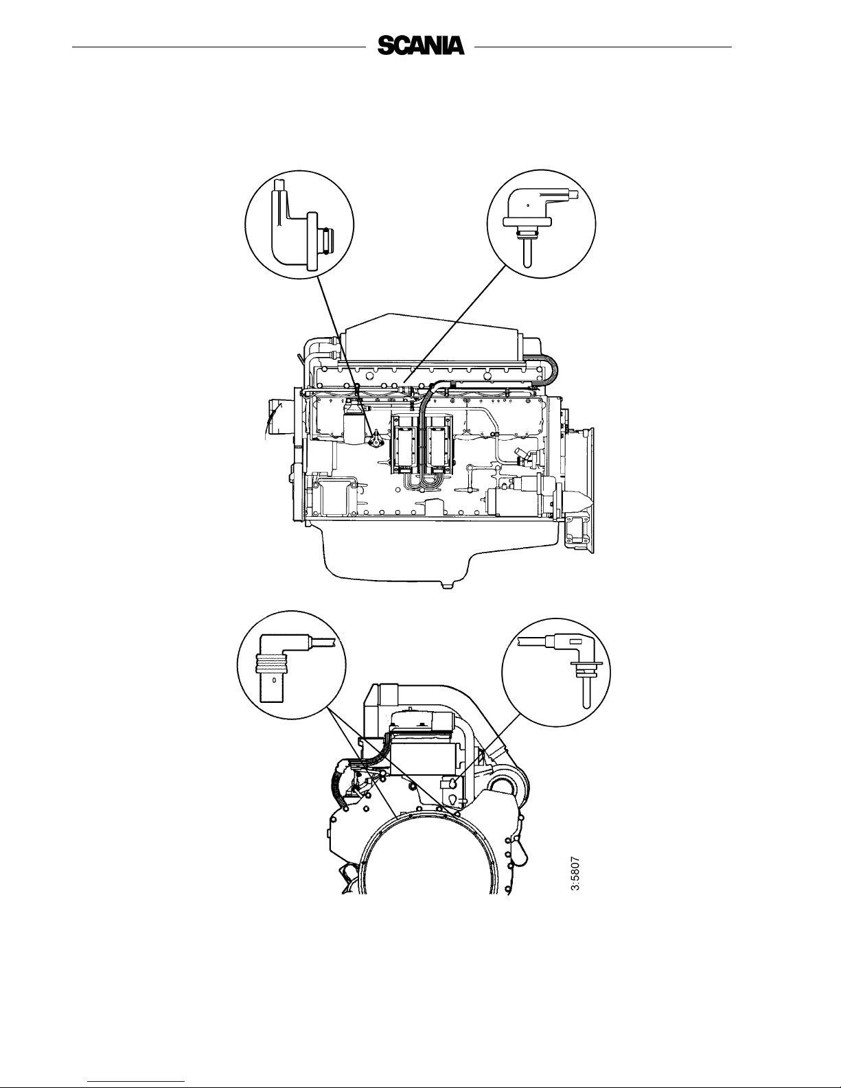
18 © Scania CV 2009
Positions of sensors for EMS with S6 on DI12
3
4
2
1
1. Oil pressure sensor
2. Charge air temperature and pressure sensor
3. Coolant temperature sensor
4. Engine speed sensor (2)
Page 19
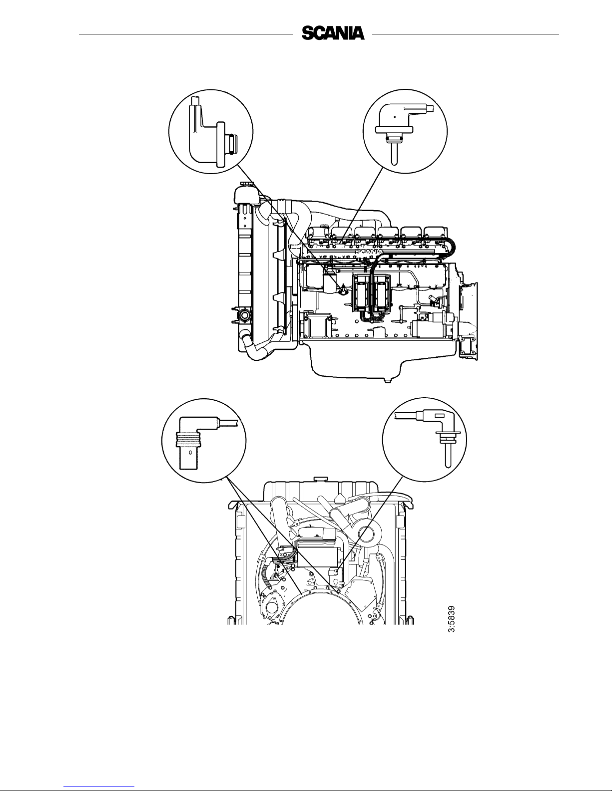
© Scania CV 2009 19
Location of sensors for EMS with S6 on DC12
2
3
4
1
1. Oil pressure sensor
2. Charge air temperature and pressure sensor
3. Coolant temperature sensor
4. Engine speed sensor (2)
Page 20

20 © Scania CV 2009
Troubleshooting using flash codes for the EMS
control unit
• The diagnostics lamp on the instrument panel(s) always comes on for
two seconds when the system is powered up.
• As soon as a fault is detected by the control unit, it is stored in the
EEPROM fault code memory and the diagnostics lamp on the
instrument panel(s) comes on.
• The diagnostic lamp will stay on for as long as a fault is active. Even if
the lamp has gone off and the fault is no longer active, the code can
generally be read off by following the instructions below.
Reading off control unit fault codes
1. Turn on the ignition.
2. Activate the diagnostics switch to the left to view the flash codes for the
control unit (EMS).
3. A fault code will then flash on the diagnostics lamp. This flash code
consists of long flashes (approximately 1 second long) and short flashes
(0.3 seconds long). Long flashes are equivalent to tens and short flashes
to units.
Example: long - short - short = fault code 12.
4. Repeat this procedure until the first flash code is repeated. This means
that the entire fault code memory has been flashed out. If the fault code
memory is empty, only one long flash approximately 4 seconds long
will be given.
5. See the flash code table on the next page for a description and to locate
the fault.
6. In order to obtain further information on the fault code, the PC-based
diagnostics tool or Scania EMS Display must be used. Contact an
authorised Scania workshop.
7. When a fault has been rectified the fault code can be erased as described
below.
Clearing fault codes
1. Switch off the ignition. If there is dual instrumentation the ignition must
be switched off on both panels.
2. Activate the diagnostics switch in the same direction as the flash codes
indicate, i.e. to the right for the coordinator (COO) or to the left for
EMS.
3. Switch on the ignition and at the same time keep the diagnostics switch
activated, to the right (COO) or to the left (EMS), for 3 seconds.
4. This will erase passive fault codes which can be read off via flash code
for the relevant system. The rest of the fault codes will remain in the
EEPROM and can only be deleted using the PC tool.
Page 21

© Scania CV 2009 21
Overview of flash codes for the EMS control unit
Code Description
Code
Description
0
No fault detected.
53
PDE in cylinder 3: The solenoid valve is not
working properly.
11
Overrevving. One or both engine speed sensors
displays a speed in excess of 3,000 rpm.
54
PDE in cylinder 4: The solenoid valve is not
working properly.
12
Engine speed sensor 1 faulty, or incorrect signal.
55
PDE in cylinder 5: The solenoid valve is not
working properly.
13
Rotation speed sensor 2 faulty, or incorrect signal.
56
PDE in cylinder 6: The solenoid valve is not
working properly.
14
Coolant temperature sensor faulty, or incorrect
signal.
57
PDE in cylinder 7: The solenoid valve is not
working properly.
15
Charge air temperature sensor faulty, or incorrect
signal.
58
PDE in cylinder 8: The solenoid valve is not
working properly.
16
Charge air pressure sensor faulty, or incorrect
signal.
59
Incorrect signal in extra analogue input.
17
Oil temperature sensor faulty, or incorrect signal.
61
Incorrect control unit shutdown.
18
Oil pressure sensor faulty, or incorrect signal.
66
Shutdown due to coolant level.
21
Coolant level sensor faulty.
68
Alternator charging incorrectly.
23
Internal fault code in the coordinator.
69
Starter motor function interrupted or not activated.
24
Accelerator pedal / brake. If the accelerator and
brake pedals have been operated simultaneously.
82
Rotation speed above ref.speed at start.
25
Accelerator pedal sensor / idling switch
Accelerator pedal sensor / kickdown switch
83
Fault in memory circuit (EEPROM) in control unit.
27
Engine shutdown bypassed.
84
Data transfer to the control unit memory
(EEPROM) has been interrupted.
28
Shutdown due to oil pressure.
85
Incorrect internal temperature in the control unit.
31
Torque limitation due to oil pressure.
86
Internal fault in the control unit: Fault in hardware
control.
32
Incorrect parameters for limp home function.
87
Fault in control unit RAM.
33
Battery voltage incorrect or no signal.
88
Internal control unit fault: Memory fault.
37
Emergency shutdown switch activated in
accordance with CAN message from coordinator.
89
Defective seal: Illegal editing of software.
43
CAN circuit faulty in the control unit.
93
Rotation speed sensors faulty or not connected.
47
Immobiliser function. Starter key code incorrect.
94
Shutdown due to high coolant temperature.
48
CAN message from the coordinator incorrect or
missing.
96
Torque limitation due to high coolant temperature.
49
Incorrect CAN version in control unit or
coordinator.
98
Incorrect voltage supply to one of the sensors.
51
PDE in cylinder 1: The solenoid valve is not
working properly.
99
Internal hardware fault in the processor (TPU).
52
PDE in cylinder 2: The solenoid valve is not
working properly.
Page 22

22 © Scania CV 2009
Troubleshooting using flash codes for the EMS
co-coordinator
• The diagnostics lamp on the instrument panel(s) always comes on for
two seconds when the system is powered up.
• As soon as a fault is detected by the coordinator, it is stored in the
EEPROM fault code memory and the diagnostics lamp on the
instrument panel(s) comes on.
• Even if the lamp has gone off and the fault is no longer active, the code
can generally be read off by following the instructions below.
Reading off coordinator fault codes
1. Turn on the ignition.
2. Activate the diagnostics switch to the right for 1 second to view the flash
codes for the coordinator (COO).
3. A fault code will then flash on the diagnostics lamp. This flash code
consists of long flashes (approximately 1 second long) and short flashes
(0.3 seconds long). Long flashes are equivalent to tens and short flashes
to units.
Example: long - short - short = fault code 12.
4. Repeat this procedure until the first flash code is repeated. This means
that the entire fault code memory has been flashed out. If the fault code
memory is empty, only one long flash (approximately 4 seconds long)
will be given.
5. See the flash code table on the next page for a description and to locate
the fault.
6. In order to obtain further information about the fault code, the PC-based
diagnostics tool or Scania EMS Display must be used. Contact an
authorised Scania workshop.
7. When a fault has been rectified the fault code can be erased as described
below.
Clearing fault codes
1. Switch off the ignition. If there is dual instrumentation the ignition must
be switched off on both panels.
2. Activate the diagnostics switch in the same direction as the flash codes
indicate, i.e. to the right for the coordinator (COO) or to the left for
EMS.
3. Switch on the ignition and at the same time keep the diagnostics switch
activated, to the right (COO) or to the left (EMS), for 3 seconds.
4. This will erase passive fault codes which can be read off via flash code
for the relevant system. The rest of the fault codes will remain in the
EEPROM and can only be deleted using the PC tool.
Page 23

© Scania CV 2009 23
Overview of flash codes for the EMS co-coordinator
1) Single speed engine
2) All-speed engine
Flash code Fault description
11
1)
Incorrect signal from the fine adjustment for the nominal engine speed signal.
11
2)
Incorrect signals from the accelerator pedal sensor.
12
1)
Incorrect signal from the resistor module for governor setting.
12
2)
Incorrect signal from the resistor module for idle and fixed speed setting.
13 No communication (EMS) with the engine.
14 Short circuit in the tachometer signal cable.
15 Faulty atmospheric pressure sensor.
17 Short circuit in the coolant temperature gauge signal cable.
18 Short circuit in the oil pressure gauge signal cable.
19 Short circuit in the oil pressure lamp signal cable.
21 Different versions of the communications protocol in the coordinator and EMS.
22 Faulty start switch or short circuit.
23 The supply voltage is too high.
24 The supply voltage is too low.
25 Check value from End of line (EOL) is incorrect.
26 Road speed sensor signal missing or incorrect.
27 The signals from the RCB (Remote Control Box) switches are implausible.
28 Incorrect signals from the droop setting switches.
29 Faulty remote start switch or short circuit.
31 No communication from the slave coordinator or the master coordinator.
32 Short circuit in the signal cable to the coolant temperature warning lamp.
33 Short circuit in the signal cable to the charge warning lamp.
34 Incorrect signal from the Fixed speed switches.
35 Fault in CAN communication.
Page 24

24 © Scania CV 2009
Starting and driving
First start
When the engine is started for the first time, carry out the maintenance points
listed under "First start" in the maintenance schedule; see page 31.
Since the points are important for satisfactory operation of the engine right
from the outset, they are also listed below.
1. Checking the oil level; see page 33.
6. Checking the coolant; see page 34.
The coolant must contain corrosion inhibitor to protect the cooling
system from corrosion.
If there is a danger of freezing:
- Only antifreeze glycol should be used in the coolant as protection
against corrosion. We recommend only nitrite-free antifreeze glycols
with the following supplier designations:
BASF G48 or BASF D542
- The concentration of glycol should be 30-60% by volume depending on
the ambient temperature. 30% glycol by volume provides anti-freeze
protection down to -16°C. See page 37.
- Never top up with water alone or glycol alone! Fluid losses must always
be replaced with pre-mixed coolant having the same glycol
concentration as that in the engine. If the glycol content drops, both antifreeze protection and protection against corrosion are impaired.
Note: A glycol concentration below 30% by volume will not provide
sufficient protection against corrosion. Glycol concentrations
higher than 60% do not improve anti-freeze protection and have
a negative effect on engine cooling capacity.
If there is no danger of freezing:
- Only Scania Corrosion Inhibitor should be used in the coolant as
protection against corrosion. The correct corrosion inhibitor content is
8-12% by volume, and this must never drop below 8% by volume. The
inhibitor in Scania Corrosion Inhibitor is free of nitrites.
- First filling: Fill up the system with water + 10% by volume Scania
Corrosion Inhibitor. Use drinking water with a pH of 6-9.
- Never top up with water alone or corrosion inhibitor alone!
Fluid losses must always be replaced with pre-mixed coolant: water
+ 10% Scania Corrosion Inhibitor by volume.
Coolant filter (not standard equipment)
Only coolant without inhibitor may be used. The use of coolant filters
increases the life of the coolant and reduces the risk of deposit corrosion.
Coolant composition:
If there is a danger of freezing:
minimum 30% glycol by
volume
maximum 60% glycol by volume
If there is no danger of freezing:
8-12% by volume
Scania Corrosion Inhibitor
(no glycol)
The recommended glycols must
not be mixed with glycol
containing nitrite-based
corrosion inhibitor.
Ethylene glycol and corrosion
inhibitor can be fatal if
imbibed.
Avoid contact with the skin.
Overdosing with Scania
Corrosion Protection and mixing
with glycol can cause sludge to
form.
If a coolant filter has been fitted
it must not contain inhibitor.
Important
!
Important
!
Important
!
WARNING
!
Page 25

© Scania CV 2009 25
12. Checking the fuel level; see page 44.
14. Checking the electrolyte level in batteries; see page 46.
15. Checking the state of charge in batteries; see page 46.
18. Checking the drive belt tension; see page 48.
Checks before running
Before running, carry out "Daily maintenance" as described in the
maintenance schedule, see page 31.
Starting the engine
If the fuel tank has been run dry or if the engine has not been used for a long
time, bleed the fuel system, see page 45.
Out of consideration for our common environment, your Scania engine has
been designed to use less fuel when starting. Using unnecessarily large
amounts of fuel when starting the engine always results in emissions of
unburnt fuel.
- Open the fuel cock, if fitted.
- Disengage the engine.
- Engines with battery master switch: Switch on the power by means of
the battery master switch.
- Start the engine with the key on the control panel (SCP).
- S6: All lamps should go out after approximately 2 seconds when starting
the engine.
Block the starting device when
working on the engine.
If the engine starts accidentally,
there is a
SERIOUS RISK OF INJURY.
Only start the engine in a well
ventilated area.
If it is run in a enclosed space,
there should be an effective
device to draw off exhaust gases
and crankcase gases.
Never use starter spray or
similar agents to help start the
engine.
An explosion may occur in the
intake manifold with a risk of
personal injury.
WARNING
!
WARNING
!
WARNING
!
Page 26

26 © Scania CV 2009
Starting at low temperatures
Local environmental requirements must be complied with. Starting aids,
engine heaters or flame start devices should be used to avoid starting
problems and white smoke.
To limit white smoke, the engine should be run at low speed and under
moderate load. A moderate load on a cold engine gives better combustion and
faster heating than warming up with no load.
Avoid running it longer than necessary at idling speed.
At temperatures below 0°C:
Note: Only use starting aids recommended by Scania.
- The starter motor may only be used for 30 seconds at a time. After that it
must rest for 30 seconds before attempting to start it again. Only 5
attempts may be made to start the engine. After that the starter motor
must rest for 15 minutes before the procedure can be repeated.
Note: If the engine is equipped with an INTERLOCK switch, this
switch should be depressed and held down until the oil pressure
has reached a sufficiently high level.
RUNNING
Check instruments and warning lamps at regular intervals.
Engine speed
The Scania tachometer is divided into different coloured sectors, as follows:
0-500 rpm red area: prohibited engine speed, passed
through when stopping and
starting.
500-700 rpm yellow area: slow idle. Engine idling is
controlled by the S6 control
system. Raised idling speed
with a cold engine.
See page 26.
700-2,200 rpm green area: normal operating speed.
The engine operating speed
range is controlled by the S6
control system.
2,200-2,600 rpm yellow/green
striped:
unsuitable operating speed.
May occur when switching off.
2,600-3,000 rpm red area: prohibited engine speed
The starter motor may only be
cranked for a maximum of
30 seconds. There is risk of
overheating. Let the starter
motor rest for 30 seconds
between each start attempt.
Important
!
Page 27

© Scania CV 2009 27
Limp home mode
If there is a fault on the normal accelerator pedal or if CAN communication is
interrupted, the following limp-home option is provided:
CAN outage or accelerator pedal malfunction (both signal and idling switch):
- The accelerator pedal value is 0% and the engine is running at normal
idling speed.
- The accelerator pedal value is 0% and the engine is running at raised
idling speed (750 rpm) if this function is activated.
Accelerator pedal malfunction but the idling switch is working:
- The accelerator pedal value can be increased slowly between 0% and
50% by using the idling switch.
CAN outage:
- The engine is switched off if the shutdown function is activated.
Coolant temperature
Normal coolant temperature when the engine is running should be 70-90°C.
The S6 control system has the following alarm levels:
- If the temperature is high, 98°C-103°C, for a certain period (1 second),
S6 will send a CAN message which switches on the warning lamp and
diagnostics lamp via the coordinator.
- If the temperature exceeds 103°C, the warning lamp and diagnostics
lamps will come on. If torque reduction is activated, the control system
will reduce the fuel quantity to 70%. A fault code is generated in the
control unit.
- At temperatures exceeding 103°C and with engine shutdown activated,
the warning lamp and diagnostics lamp come on and the engine is
switched off. If the override function is activated, only torque reduction
takes place when this function is activated. A fault code is generated in
the control unit.
After an alarm, approved values should be registered for more than 2 seconds
to reset the alarm.
Excessively high coolant temperature can damage the engine.
If run for extended periods under an extremely light load, the engine may
have difficulty in maintaining normal operating temperature. However, the
temperature will rise to a normal level again when the load on the engine is
increased.
Page 28

28 © Scania CV 2009
Oil pressure
Maximum oil pressure:
warm engine running at a speed above 800 rpm 6 bar
Normal oil pressure:
warm engine at operating speed 3-6 bar
Minimum oil pressure:
warm engine running at a speed of 1,000 rpm 2.3 bar
The control system has the following alarm levels:
- at a speed of less than 1,000 rpm and an oil pressure of less than 1.0 bar
- at a speed of more than 1,000 rpm and an oil pressure of less than 2.3 bar
for longer than 5 seconds.
The following functions are available if there is an alarm:
- Alarm which only switches on the warning lamp and diagnostics lamp.
- Alarm which switches on the warning lamp and diagnostics lamp as
well as torque reduction if this function is activated (70% of fuel
quantity).
A fault code is generated in the control unit.
- Alarm which switches on the warning lamp and diagnostics lamp. The
engine is switched off if engine shutdown is activated. If the override
function is activated, only torque reduction takes place when this
function is activated.
A fault code is generated in the control unit.
After an alarm, approved values should be registered for more than
1 second to reset the alarm.
High lubricating oil pressure
(above 6 bar) is normal when
starting a cold engine.
Page 29

© Scania CV 2009 29
Charging indicator lamp
If the lamp comes on during operation:
- Check and adjust the alternator drive belts as described under the
maintenance point. See page 48.
- If the charging indicator lamp is still on, this could be due to an
alternator fault or a fault in the electrical system.
Stopping the engine
1. Run the engine without a load for a few minutes if it has been run
continuously with a heavy load.
2. Stop the engine with the stop button or the starter key (depending on
version). Keep the stop button depressed until the engine has stopped
completely.
3. Set the control switch to the "0" position.
4. Engines with battery master switch: Switch the power off with the
battery master switch.
Note: 10 prohibited engine stops will cause torque reduction (70% of
fuel quantity). To reset the engine, switch off the engine once in
the prescribed manner.
Checks after running
- Check that the power is cut from the battery master switch and that the
control switch is in the "0" position.
- Fill the fuel tank. Make sure that the filler cap and the area round the
filler opening are clean to avoid contamination of the fuel.
- If there is a risk of freezing, the cooling system must contain enough
glycol. See pages 24 and 37.
- At temperatures below 0°C: prepare for the next start by connecting the
engine heater (if fitted).
There is danger of turbocharger
damage and post boiling if the
engine is stopped without
cooling.
Coolant should be topped up
when the engine is stopped after
the first start.
Block the starting device when
working on the engine.
If the engine starts accidentally,
there is a
SERIOUS RISK OF INJURY.
The power must not be switched
off before the engine has
stopped.
The system is pressurised.
Major risk of burns.
Important
!
Important
!
Important
!
WARNING
!
WARNING
!
Page 30

30 © Scania CV 2009
Maintenance
The maintenance programme covers 20 points, divided into the following
main groups:
Lubricating oil system . . . . . . . . . . . . . . . . .page 28
Cooling system . . . . . . . . . . . . . . . . . . . . . . .page 32
Air cleaner . . . . . . . . . . . . . . . . . . . . . . . . . .page 38
Fuel system. . . . . . . . . . . . . . . . . . . . . . . . . . page 40
Electrical system, batteries, etc. . . . . . . . . . .page 42
Miscellaneous. . . . . . . . . . . . . . . . . . . . . . . .page 44
The maintenance points are divided into intervals as follows:
Daily maintenance
Maintenance before the first start
Maintenance after the first 400 hours of operation
Periodic maintenance every 200 hours of operation (carried out at 200, 400,
600, 800, etc. hours)
Periodic maintenance every 400 hours of operation (carried out at 400, 800,
1,200, 1,600, etc. hours)
Periodic maintenance every 1,200 hours of operation (carried out at 1,200,
2,400, 3,600, etc. hours)
Periodic maintenance every 2,400 hours of operation (carried out at 2,400,
4,800, etc. hours)
Periodic maintenance every 4,800 hours of operation (carried out at 4,800,
9,600 etc. hours)
Annual maintenance
Maintenance every 5 years
Engines with few hours of operation
Emergency generator sets and the like that are not used regularly should be
test run and checked in accordance with the generator set manufacturer’s
instructions.
Run the engine until it reaches operating temperature and then carry out the
maintenance points below:
1. Checking the oil level.
5. Checking the coolant level.
8. Checking the vacuum indicator.
12. Checking the fuel level.
14. Checking the electrolyte level in batteries.
15. Checking the state of charge in batteries.
16. Cleaning the batteries.
19. Check for leaks, rectify as necessary.
Block the starting device when
working on the engine.
If the engine starts accidentally,
there is a
SERIOUS RISK OF INJURY.
For engines with few operating
hours that do not receive
periodic maintenance according
to the maintenance schedule on
page 29, maintenance should be
carried out in accordance with
the schedule:
"Annually"
"Every 5th year"
Important
!
WARNING
!
Page 31

© Scania CV 2009 31
Maintenance schedule
1. More often if required.
2. Earlier if the vacuum indicator shows red.
3. If inhibitor has not been topped up for five years, the coolant should be changed.
Daily
First
time at
Interval At least
First start
400 h
200 h
400 h
1,200 h
2,400 h
4,800 h
Annually
Every 5 years
Lubricating oil system, page 28
1. Checking the oil level
zz
2. Oil change
z1 z
3. Cleaning the lubricating oil cleaner.
z1 z
4. Renewing the oil filter
z1 z
Cooling system, page 32
5. Checking the coolant level
z
6. Checking the coolant
zz3 z
7. Cleaning the cooling system
z1 z
Air cleaner, page 38
8. Test reading of vacuum indicator
z
9. Cleaning the coarse cleaner
z1 z
10. Cleaning or renewing the filter element
z2 z
11. Renewing the safety cartridge
zz
Fuel system, page 40
12. Checking the fuel level
zz
13. Changing the main filter and water separating filter
z1 z
Electrical system, page 42
14. Checking the electrolyte level in batteries
zz z
15. Checking the state of charge in batteries
zzz
16. Cleaning the batteries
zz
17. Checking the coolant level monitor
zz
Miscellaneous, page 44
18. Checking the drive belt
zzz
19. Check for leaks, rectify as necessary
z
20. Checking and adjusting valve clearances
zz
21. Checking and adjusting the unit injector rocker arms
zz
22. Renewing (or cleaning) the closed crankcase ventilation
valve
z
Page 32

32 © Scania CV 2009
Lubricating oil system
Oil grade
The engine oil must at least meet the requirements for one of the following
oil classifications:
-ACEA E3, E4 or E5
- The Total Base Number (TBN) should be minimum 12-13 (ASTM
2896).
- Check with your oil supplier that the oil meets these requirements.
- Specified oil change intervals apply provided that the sulphur content of
the fuel does not exceed 0.3% by weight. If the sulphur content is
greater than 0.3% but no more than 1.0%, the oil change interval must
be halved (200 h).
- Viscosities are shown in the figure below.
- For operation at extremely low ambient temperature: Consult your
nearest Scania representative on how to avoid starting difficulties.
Oil analysis
Some oil companies can offer analysis of the engine oil. Such analysis
measures the oil’s TBN (Total Base Number), TAN (Total Acid Number),
fuel dilution, water content, viscosity and the quantity of wear particles and
soot in the oil.
The result of a series of analyses is used as the basis for establishing a
suitable oil change interval.
If the conditions are changed, a new oil analysis programme must be carried
out to establish the new change interval.
Additives must not be used.
The oil should be suitable for all
temperature variations until the
next oil change.
-40-30-20-100 10203040
°C
SAE 10W-30
SAE 20W-30
SAE 30
SAE 40
SAE 50
SAE 5W-30
SAE 15W-40
Important
!
Page 33

© Scania CV 2009 33
1. Daily:
Checking the oil level
Note: Before checking oil level: Leave the engine switched off for at
least 1 minute.
- The correct level is between the marks on the dipstick. Top up when the
level is at the lower mark.
- For the correct oil grade, see page 32.
Checking oil level during operation
On some engines the oil level can be checked during operation.
- Remove the oil filler cap to release the pressure in the crankcase.
- Check the level on the dipstick. Correct oil level: 10 mm below the Min.
or Max. mark.
2. Every 400 hours:
Oil change
Note: If the engine is used for especially demanding operations,
particularly in a dusty environment or if the deposits in the
centrifugal cleaner are thicker than 20 mm: change the oil more
frequently.
- Unscrew the oil plug and drain the oil when the engine is hot.
- In certain engines the oil is pumped out by means of a bilge pump.
- Clean the magnet on the oil plug.
- Refit the oil plug and top up with oil.
- Check the level on the oil dipstick.
Max. 33 dm
3
Min. 28 dm
3
1 dm3 = 1 litre
Maximum angles of inclination during operation
Maximum permissible angles during operation vary, depending on the type of
oil sump, see illustration.
Note: The specified angles may only occur intermittently.
35°
25°
25°
35°
The oil may be hot.
Wear protective gloves and
goggles.
Max.
Min.
Use a container to avoid spillage
when changing the oil. Dispose
of used oil through an
authorised waste disposal
contractor.
WARNING
!
Help protect our
environment!
Page 34

34 © Scania CV 2009
3. Every 400 hours:
Cleaning the oil cleaner
(in connection with oil change)
- Clean the cover. Unscrew the nut and remove the cover.
- Lift out the rotor and wipe the outside. Unscrew the rotor cover nut
about one and a half turns.
- If the rotor nut is jammed:
Turn the rotor upside down and fasten the nut in a vice, and turn the
rotor one and a half turns counterclockwise by hand, or use an M20 nut
as illustrated.
Note: The rotor must never be put in a vice.
- Hold the rotor and tap lightly on the rotor nut with a plastic mallet or
against the workbench, so that the rotor bowl comes loose from the
bottom plate. Never strike on the rotor directly as this may damage the
bearings.
- Unscrew the nut and remove the rotor cover.
- Remove the strainer. If the strainer has seized in the rotor bowl, pry
carefully using a screwdriver between the rotor bowl and the strainer.
- If the strainer has seized in the rotor, pry carefully between the rotor and
the strainer.
- Scrape off the deposits from the inside of the rotor cover. If there are no
deposits, this indicates that the cleaner is not working properly.
- If the deposits are thicker than 28 mm: clean more often.
Open the cover carefully. The
oil may be hot.
WARNING
!
Page 35

© Scania CV 2009 35
- Wash all parts in diesel oil.
- Make sure the nozzles on the rotor are not blocked or damaged.
- Check that the bearings are undamaged. If they are damaged the entire
rotor must be renewed.
- Fit a new O-ring on the rotor and fit the strainer.
- Reassemble the rotor.
- Tighten the rotor nut firmly by hand.
- Check that the shaft is not loose. If it is loose, use locking compound
561 200 and torque tighten to 34 Nm using tool 98 421.
- In order to tighten the rotor shaft, it is necessary to modify socket
wrench 98 421:
- Drill out the threads from a M20 nut so that it fits on the square drive
of the socket wrench.
- Weld the nut into place.
- Refit the rotor.
- Check that it rotates easily by rotating it manually.
- Fit a new O ring on the bowl and fit the bowl.
- Screw the bowl on and tighten the lock nut to 15 Nm.
Tighten the nut carefully so as not to damage the rotor shaft, nut or cover.
Functional inspection
The rotor rotates very fast and should continue to rotate when the engine has
stopped.
- Stop the engine when it is warm.
- Listen for a whirring sound from the rotor or feel whether the cleaner
housing is vibrating.
The rotor normally continues spinning for 30-60 seconds after the engine has
stopped.
If not: dismantle and check.
Page 36

36 © Scania CV 2009
4. Every 400 hours:
Renewing the oil filter
(in connection with oil change)
- Remove the old filter.
- Fit a new Scania genuine filter. Oil the seal on the filter before fitting.
- Tighten the filter by hand.
Never use tools for this. The filter could sustain damage, obstructing
circulation.
- Start the engine and check for leaks.
Important! If the deposits in the centrifugal cleaner are more than
20 mm thick, the oil filter must be renewed more often. The
same is true for cleaning the centrifugal filter and
changing the oil.
Cooling system
5. Daily:
Checking coolant level
- Open the expansion tank filler cap and check the coolant level.
- Correct level: (Scania plastic expansion tank)
- Cold engine: The coolant should be level with the bottom of the
filler neck.
- Hot engine: The coolant should be about 25 mm above the
lower edge of the filler hole.
- Other types of expansion tank according to the instructions of the fitter.
- Top up the coolant as necessary; see point 6.
Note: When filling large amounts of coolant:
Never pour cold coolant into a hot engine. This could crack the
cylinder block and cylinder head.
Always top up with pre-mixed
coolant.
Open the cap carefully.
Water and steam can spray out.
Use a container to avoid spillage
when renewing the filter.
Dispose of used filters through
an authorised waste disposal
contractor.
Important
!
WARNING
!
Help protect our
environment!
Page 37

© Scania CV 2009 37
6. Every 2,400 hours:
Checking coolant
Coolant should be checked as follows:
a) Check the appearance of the coolant.
b) Coolant with glycol only: Check the glycol content.
c) Coolant containing only Scania Corrosion Inhibitor: check the corrosion
inhibitor content
The composition of the coolant is described in more detail under
"Starting and running"
a)
Checking the appearance of the coolant
- Pour a small amount of coolant in a container, and check that the coolant
is pure and clear.
- If the coolant is contaminated or cloudy: Consider changing the coolant.
- Water for the coolant must be clean and free from contamination.
- Use drinking water with a pH of 6-9.
b)
Checking the glycol content
If there is a danger of freezing, use only glycol as an anti-corrosive in the
coolant.
- Cooling systems with glycol should contain at least 30% glycol by
volume to provide acceptable protection against corrosion.
- 30% glycol by volume provides protection against freezing to -16°C. If
additional protection against freezing is required, see the table on the
next page to help you calculate how much glycol you need.
We recommend only nitrite-free antifreeze glycols with the following
supplier designations:
BASF G48 or BASF D542
- Always add glycol if the glycol content drops below 30% by volume. A
glycol content above 60% by volume will not provide greater protection
against freezing.
- The table shows the temperature at which ice starts to form. The engine
will freeze and break at appreciably lower temperatures; see diagram.
- Ice forming in the coolant often causes malfunctioning without any risk
of damage. The engine should not be subjected to heavy loads when ice
starts to form.
Note: The coolant should be changed when the cooling system is
cleaned: every 4,800 hours or at least every 5 years.
Important! If a coolant filter is used in the cooling system it must not
contain an inhibitor.
Coolant composition:
If there is a danger of freezing:
minimum 30% glycol by
volume
maximum 60% glycol by
volume
If there is no danger of freezing:
8-12% by volume
Scania Corrosion Inhibitor
The coolant should be pre-
mixed when it is poured into the
cooling system.
Never top up with only water or
only glycol.
Ethylene glycol is highly
dangerous if imbibed and can
prove fatal.
Avoid skin contact with glycol.
The recommended glycols must
not be mixed with glycol
containing nitrite-based
corrosion inhibitor.
Risk of sludge build-up and
reduced cooling capacity.
Important
!
Important
!
WARNING
!
Page 38

38 © Scania CV 2009
A
A = Area to be avoided. Only for calculating glycol mix.
Coolant freezing point (when ice starts to form) for different glycol mixes
Glycol % by
volume
15 20 25 30 35 40 45 50 60
Cooling system
volume, dm
3
Ice slush starts to
form at °C
-6 -9 -12 -16 -22 -27 -36 -46 -55
Glycol dm
3
(litres)
5 6 8 9 11 12 14 15 18 30
6 8 10 12 14 16 18 20 24 40
8 10 13 15 18 20 23 25 30 50
9 12 15 18 21 24 27 30 36 60
11 14 18 21 25 28 32 35 42 70
12 16 20 24 28 32 36 40 48 80
14 18 23 27 32 36 41 45 54 90
15 20 25 30 35 40 45 50 60 100
17 22 28 33 39 44 50 55 66 110
18 24 30 36 42 48 54 60 72 120
20 26 33 39 46 52 59 65 78 130
21 28 35 42 49 56 63 70 84 140
23 30 38 45 53 60 68 75 90 150
24 32 40 48 56 64 72 80 96 160
26 34 43 51 60 68 77 85 102 170
27 36 45 54 63 72 81 90 108 180
29 38 48 57 67 76 86 95 114 190
30 40 50 60 70 80 90 100 120 200
Curve A: Ice formation starts (ice slush)
Curve B: Temperature at which there is a risk of damage by freezing
1. Safe range
2. Malfunctions may occur (ice slush)
3. Risk of damage by freezing
Characteristics of glycol at low temperatures:
- Example with 30% glycol by volume
- Ice slush starts to form at -16°C.
- There is a risk of malfunctions at -30°C
- No risk of damage by freezing with a minimum
content of 30% glycol by volume
Antifreeze glycol, % by volume
Page 39

© Scania CV 2009 39
c)
Checking the corrosion inhibitor
There must always be sufficient corrosion protection (inhibitor) in the coolant
to protect the cooling system against corrosion.
If there is no danger of freezing, only Scania Corrosion Inhibitor should be
used in the coolant.
The inhibitor in Scania Corrosion Inhibitor is free of nitrites.
The correct corrosion inhibitor content is 8-12% by volume.
- Topping up with 1.0% Scania Corrosion Inhibitor by volume should be
done after every 2,400 hours of operation.
- Never top up with water alone or corrosion inhibitor alone!
Fluid losses must always be replaced with pre-mixed coolant: water
+ 10% Scania Corrosion Inhibitor by volume.
Note: The coolant should be changed when the cooling system is
cleaned: every 4,800 hours or at least every 5 years.
Changing coolant
1. Remove the filler cap from the expansion tank.
2. The coolant is drained at two points:
- the lowest point of the cylinder block, see illustration.
- the lowest point of the cooling system.
3. Close the cocks.
4. Top up with coolant through the expansion tank’s filler hole.
Mix coolant as described on page 35.
Use a container to avoid spills
when changing the coolant.
Dispose of used coolant through
an authorised waste disposal
contractor.
If a coolant filter has been fitted
it must not contain inhibitor.
Mixing with glycol or the use of
too much corrosion protection
can lead to build up of sludge
and reduced cooling capacity.
Corrosion inhibitor is highly
dangerous if ingested and can
prove fatal.
Avoid contact with the skin.
Important
!
Important
!
WARNING
!
Help protect our
environment!
Page 40

40 © Scania CV 2009
7. Every 4,800 hours:
Cleaning the cooling system
Note: If necessary, the cooling system should be cleaned more often.
External cleaning
Radiator
- Check that the radiator is not clogged on the air side and that the cooling
fins are not damaged.
- Carefully scrape the deposit off the radiator’s cooling fins. If necessary,
a paraffin-based engine cleaner can be used.
- Bent fins can be straightened using a wire brush, for example, and
exercising care.
Charge air cooler, DI engine
1. Drain the coolant from the engine, see "Changing the coolant".
2. Detach the intake manifold from the turbo.
3. Detach the charge air cooler’s inlet and outlet connections.
4. Unbolt the charge air cooling package from the intake manifold. The
charge air element is integrated into the housing.
Take care not to damage the element’s water connections.
5. Clean the outside of the core. This is especially important if the engine is
equipped with closed crankcase ventilation. Use a paraffin-based engine
cleaner.
6. Clean and degrease the sealing surfaces on the element and on the intake
manifold with a spirit-based cleaning agent.
7. Apply a smooth bead of sealing agent (silicone 816 064), approximately
2-3 mm, onto the intake manifold sealing surface.
8. Assemble the charge air cooler within 15 minutes of applying the
sealant. Tighten the bolts to 26 Nm.
9. Refit the inlet and outlet connections with new
O-rings.
10. Refit the delivery pipe clamps.
11. Connect the intake manifold from the turbo.
12. Fill up with coolant according to the
specification on page 35.
Important! Let the sealing compound harden
for at least 24 hours before the
engine is used again.
1. Charge air
cooler element
2. O-ring
3. Sealant 816 064
4. Intake manifold
1
2
3
4
The cooling system must never
be cleaned with caustic soda.
There is a risk of damage to
aluminium parts.
Important
!
Page 41

© Scania CV 2009 41
Internal cleaning
Removing oil and grease
- If possible, run the engine until it has reached operating temperature and
then drain the cooling system.
- Remove the thermostats.
- Fill the system with clean, hot water mixed with liquid dishwasher
detergent designed for household use.
Concentration 1% (0.1/10 l).
- Run the engine until warm for about 20-30 minutes. Do not forget the
cab heating system (if fitted).
- Drain the cooling system.
- Fill the system again using clean, hot water and run the engine for about
20-30 minutes.
- Drain the water from the system.
- Refit the thermostats.
- Top up the system with new coolant according to the specification on
page 35.
Removing deposits
- If possible, run the engine until it has reached operating temperature and
then drain the cooling system.
- Remove the thermostats.
- Fill the system with clean, hot water mixed with some of the radiator
cleaning agent available on the market which is based on sulphamic acid
and contains dispersing agents. Follow the manufacturer’s instructions
for the concentration and cleaning period.
- Run the engine for the specified time and then drain the cooling system.
- Refill the system with hot water and run the engine for about
20-30 minutes.
- Drain the water from the system.
- Refit the thermostats.
- Top up the system with coolant according to the specification on
page 35.
When handling cooling system
detergent:
read the warning text on the
containers.
Use a container to avoid spills
when changing the coolant.
Dispose of used coolant through
an authorised waste disposal
contractor.
WARNING
!
Help protect our
environment!
Page 42

42 © Scania CV 2009
Air cleaner
8. Daily:
Test reading of vacuum indicator
If the red indicator bar is entirely visible, change or clean the air cleaner filter
element, point 10. This is particularly important if the engine is run at high
loads and high speed.
9. Every 200 hours:
Cleaning the air cleaner’s coarse
cleaner
1. Remove the cover from the coarse cleaner (2).
2. Remove the conical coarse separator. Empty out the particles of dirt and
clean it.
3. Fit the coarse cleaner as shown in the figure and screw the cover into
place.
10. Every 1,200 hours:
Cleaning or changing filter element
Note: Clean or renew the filter element earlier if the vacuum indicator
shows red.
Dismantling
1. Remove the cover from the air cleaner.
2. Renew or clean the filter element.
Note: There is always a risk that the filter element will be damaged
during cleaning. The filter element can only be cleaned a
maximum of four times. After cleaning, it has poorer dust
capacity than a new filter element.
3. Mark the filter when it has been cleaned.
Cleaning the filter element
- Carefully blow the filter element clean using dry compressed air from
the inside.
Note: This filter element must not be washed with water.
1. Cover
2. Filter element
3. Filter house
Only use genuine Scania air
filters.
Renew the filter element if it is
damaged.
Danger of engine damage if the
filter element is damaged.
Never start the engine without
the air filter.
There is a risk of injury or
engine damage.
1
2
3
The coarse cleaner must always
be fitted in an upright position.
1. Filter element
2. Coarse cleaner
3. Cover
4. Vacuum indicator
43
21
Important
!
Important
!
WARNING
!
Page 43

© Scania CV 2009 43
Check
- Insert a torch into the element and check from the outside that there are
no holes or cracks in the filter paper.
- Renew the filter element if it has the slightest damage. Danger of engine
damage.
Assembly
1. Assemble the air cleaner in reverse order.
2. Reset the vacuum indicator by pressing the button.
11. Every 2,400 hours:
Changing safety cartridge
Note: Not all filters are equipped with a safety cartridge. When
changing the safety cartridge, take great care to ensure that no
dirt or other impurities can get into the engine.
1. Remove the cover from the air cleaner.
2. Remove the filter element.
3. Remove the safety cartridge.
4. Fit a new genuine Scania safety cartridge.
5. Renew or clean the filter element, see point 10.
6. Assemble the air cleaner.
1. Safety cartridge
Air cleaner with safety cartridge
1
Do not remove the safety
cartridge unnecessarily.
Important
!
Never clean the
safety cartridge.
Important
!
Page 44

44 © Scania CV 2009
Fuel system
12. Daily:
Checking fuel level
- Top up with fuel if necessary.
- If the tank has been run dry, bleed the fuel system, see point 13.
13. Every 1,200 hours:
Renewing the fuel filter
Fuel tanks
- Drain any water from the fuel tanks.
Filter
The filter consists of a filter unit.
- Wash the outside of the filter and unscrew it. Discard the filter according
to environmental requirements.
- Fit the new filter and tighten it by hand.
Never use tools for this. The filter could sustain damage, obstructing
circulation.
- Bleed the fuel system as described below.
- Start the engine and check for leaks.
Water separating filter
- Drainage must be carried out when filling fuel.
- The filter must be changed at the same renewal interval as the main
filter.
- Close the cock (1) upstream of the filter.
- Unscrew the container and drain valve (3).
- Unscrew and change the filter (2). Lubricate the seal before tightening
the new filter by hand.
- Screw the container and drain valve into position.
- Open the cock (1).
- Bleed the fuel system after renewing both filters.
Use a container to avoid spillage
when bleeding and renewing
components.
Use only genuine Scania fuel
filters.
1. Shut-off cock
2. Filter
3. Drain valve
Observe the utmost cleanliness
when working on the fuel
system.
There is a risk of engine
malfunction and damage to the
injection equipment.
Important
!
Important
!
Help protect our
environment!
Page 45

© Scania CV 2009 45
Bleeding the fuel system
- Attach a clear plastic hose to the bleed nipple (1) to channel fuel into a
container. The bleed nipple is located at the end of the fuel manifold at
the front of the engine.
- Open the bleed nipple.
- Pump the hand pump (2) until fuel without air bubbles flows out of the
opened bleed nipple.
• If the system is completely empty, it will take approximately
250 strokes.
• After renewing the fuel filter, it will take approximately 170 strokes.
• Approximately 150 strokes are required to bleed the fuel manifold.
- Close the bleed nipple and remove the hose.
- Undo the banjo screw for overflow valve (3) slightly. Pump the hand
pump an additional 20 strokes until the overflow valve opens.
If the engine fails to start after bleeding:
- Open the bleed nipple again and pump the hand pump until fuel
without air bubbles flows out.
- Tighten the bleed nipple. Start the engine and check for leaks.
1
2
3
Use a container to avoid spillage
when bleeding and renewing
components.
Help protect our
environment!
Page 46

46 © Scania CV 2009
Electrical system
14. Every 200 hours:
Checking the electrolyte level in
batteries
1. Unscrew the plugs and check the electrolyte level in all cells.
2. Top up with distilled water until the level is 10-15 mm above the plates.
15. Every 1,200 hours:
Checking state of charge in batteries
- Check the density with an acid tester.
In a fully-charged battery it should be:
1.280 at +20°C
1.294 at 0°C
1.308 at -20°C
- If the density is below 1.20, the battery must be charged. A discharged
battery freezes at -5°C.
Do not boost charge the battery. This will damage the battery in the
long run.
16. Every 1,200 hours:
Cleaning batteries
1. Clean batteries, cables and cable terminals.
2. Check that all cable terminals are firmly tightened.
3. Grease the battery terminal posts and cable terminals with Vaseline.
Wear gloves and protective
goggles when charging and
handling batteries.
The batteries contain a highly
corrosive acid.
Do not connect the terminals
incorrectly.
This can cause serious damage
to the electrical system.
If the terminals are shorted,
sparking will occur.
Avoid naked flames or sparks
near the batteries.
When the batteries are charged,
oxyhydrogen gas is formed
which is flammable and
explosive.
WARNING
!
WARNING
!
WARNING
!
Page 47

© Scania CV 2009 47
Renewing the battery
Removing
1. Disconnect the negative cable (-) from the battery (cable connected to
earth).
2. Disconnect the positive cable (+) from the battery (cable connected to
starter motor).
Fitting
1. Connect the positive cable (+) to the battery (cable connected to starter
motor).
2. Connect the negative cable (-) to the battery (cable connected to earth).
17. Every 1,200 hours:
Checking coolant level monitor
(Optional equipment)
1. Start the engine.
2. Lower the coolant level in the expansion tank.
3. Automatic stop in the event of a fault: The engine stops, the indicator
lamp comes on and the buzzer (if fitted) sounds if there is no fault in the
level monitor. If the function is connected via the coordinator, the
emergency stop fault code will be generated and can be read off on the
diagnostics lamp.
4. No automatic stop in the event of a fault: The indicator lamp comes on
and the buzzer (if fitted) sounds if there is no fault in the level monitor.
5. Top up coolant to the correct level, see page 36.
Do not connect the terminals
incorrectly.
This can cause serious damage
to the electrical system.
If the terminals are shorted,
sparking will occur.
Dispose of used batteries
through an authorised waste
disposal contractor.
2-pin level monitor installed in the
expansion tank for radiators
supplied by Scania
Use a container to avoid spills
when draining the coolant.
Dispose of used coolant through
an authorised waste disposal
contractor.
WARNING
!
Help protect our
environment!
Help protect our
environment!
Page 48

48 © Scania CV 2009
20 Nm 2 Nm
+
-
307 939
20 Nm 2 Nm
+
-
307 938
Miscellaneous
18. Every 1,200 hours:
Checking drive belt
- If the drive belt (1), which is a poly-V belt, is worn or damaged it must
be renewed.
- Also check that the automatic belt tensioner (2) is in proper working
order and keeps the drive belt correctly tensioned.
- On installations with dual belt circuits, the second belt circuit has two
drive belts with one manual belt tensioner. These drive belts should be
tensioned to 20 Nm ±2 Nm as illustrated.
Page 49

© Scania CV 2009 49
19. Daily:
Look for leakage, rectify as necessary
- Start the engine.
- Check for oil, coolant, fuel, air and exhaust leaks.
- Tighten or renew leaking connections. Check the overflow holes (1)
(below the side covers) which show whether the O-rings between the
cylinder liners and crankcase are leaking, see figure.
a) If coolant is running out, the O-ring is leaking.
b) If lubricating oil is running out, the liner shelf is leaking.
- Check that the coolant pump drain hole (2) is not clogged, see figure. If
there is a leak, renew the pump seal or the complete coolant pump.
A small amount of leakage from the overflow holes during the engine
running-in period is normal. (Sealing rings and O-rings are lubricated
with soap or oil when fitted).
- This leakage normally stops after a time.
Take care to ensure that any
leaks do not cause pollution.
If serious leakage occurs,
contact your nearest Scania
workshop.
Important
!
Help protect our
environment!
Page 50

50 © Scania CV 2009
20. Every 2,400 hours:
Check and adjust valve clearance
Note: Checking and adjusting valve clearances should also be done
after the first 400 hours of operation.
Valve clearances should be adjusted when the engine is cold, at least
30 minutes after running.
The rocker cover gaskets should be renewed as necessary. Tightening
torques: 26 Nm.
Intake valve clearance: 0.45 mm.
Exhaust valve clearance: 0.70 mm.
Tightening torque for lock nut: 35 Nm.
Block the starting device when
working on the engine.
If the engine starts out of
control, there is a
SERIOUS RISK OF INJURY.
Openings for reading
on the flywheel housing
Readings can be taken from the flywheel through covers in the flywheel
housing either from above or underneath depending on access when fitting.
Up or down is shown on the flywheel. Both openings are fitted with a cover at
delivery.
WARNING
!
Page 51

© Scania CV 2009 51
Order of adjustment
- Turn the flywheel counterclockwise so that the marks on the flywheel
can be seen in the lower opening in the flywheel housing (depending on
which opening the reading is to be taken from). Refer to table.
- Measure the valve clearance with a feeler gauge and adjust the valves as
per the order of adjustment in the table below. Correct valve clearances
are also given on the instruction plate on one of the rocker covers.
- Checking and adjustment of the rocker arms for the PDE injectors
should be done together with the valve clearance check/adjustment. See
step 21.
- If it is not possible to take a reading in one of the covers, observe the
valve overlap, turn the flywheel counterclockwise 120° (1/3 turn) at a
time and adjust the valves according to the table below and the unit
injectors as described on the next page.
Mark on flywheel
(reading taken through the
lower opening)
Valve overlap on
cylinder
Adjust the valves
on cylinder
TDC Down (0°) 1 6
120° 5 2
240° 3 4
TDC Down (360°) 6 1
120° 2 5
240° 4 3
Mark on flywheel
(reading taken through the
upper opening)
Valve overlap on
cylinder
Adjust the valves
on cylinder
TDC Up (0°) 1 6
300° 5 2
60° 3 4
TDC Up (360°) 6 1
300° 2 5
60° 4 3
5
4
3
2
1
6
FLYWHEEL
Cylinder numbering
Page 52

52 © Scania CV 2009
21. Every 2,400 hours
Checking and adjusting the unit
injector rocker arms
Note: Checking/adjusting the rocker arms for the PDE injectors
should also be done together with the valve clearance
check/adjustment after the first 400 hours of operation.
Important! The PDE 31 unit injector is adjusted using setting tool
99 414 or a digital sliding calliper.
The PDE32 unit injector is adjusted using setting tool
99 442 or a digital sliding calliper.
This adjustment is essential as a fault in the position of the
unit injector can result in poor performance and possible
breakdown.
Readings can be taken from the flywheel through covers in the flywheel
housing either from above or underneath depending on access when fitting.
Up or down is shown on the flywheel. Both openings are fitted with a
blanking piece on delivery; see illustration on page 46.
Measurement A=
PDE31: 66.9 ±0.1 mm
PDE32: 69.9 ±0.1 mm
Measurement B=
PDE31: 36.5 mm
PDE32: 38.8 mm
Page 53

© Scania CV 2009 53
Order of adjustment
Turn the flywheel counterclockwise so that the marks on the flywheel can be
seen in the lower opening in the flywheel housing (depending on which
opening the reading is to be taken from). Refer to table.
Mark on flywheel
(reading taken through the
lower opening)
Valve overlap on
cylinder
Adjust injector
rocker arm on
cylinder
TDC Down (0°) 1 2
120° 5 4
240° 3 1
TDC Down (360°) 6 5
120° 2 3
240° 4 6
Mark on flywheel
(reading taken through the
upper opening)
Valve overlap on
cylinder
Adjust injector
rocker arm on
cylinder
TDC Up (0°) 1 2
300° 5 4
60° 3 1
TDC Up (360°) 6 5
300° 2 3
60° 4 6
Page 54

54 © Scania CV 2009
PDE31:
1. Firstly, measure the distance (A) between plane (a) and the top edge of
the valve spring washer on the unit injector using a digital sliding
calliper. See figure.
2. Dimension (A) should be 66.9 mm for PDE31 (dimension B=36.5 mm).
3. The dimension is adjusted by undoing the lock nut and screwing the
rocker arm adjusting screw (1) to the correct measurement.
WARNING! Take care when carrying out the adjustment if the
dimension is well outside the adjustment dimension. The
spring is pre-tensioned and can cause personal injury if it is
released.
4. Position setting tool 99 414 with the metal plate around the injector
spring.
5. Finely adjust dimension (A ) by simultaneously using a finger to sense
that the small piston (2) is level with the flat upper surface of the tool. It
is possible to feel differences of less than a tenth of a millimetre.
6. If the setting tool is not available, a digital sliding calliper can also be
used for fine adjustment. The rocker position is adjusted using the
adjusting screw to 66.9 +/-0.1 mm as stated above.
7. Tighten the adjusting screw lock nut to 39 Nm and remove the tool.
Note: No further checking or adjustment of the unit injector, such as
checking the opening pressure, must be done. If an injector is
defective, the whole injector must be replaced.
Piston level with the flat surface.
Adjustment is correct.
Piston above or below the flat
surface. Adjustment necessary.
66.9
99 414
Page 55

© Scania CV 2009 55
PDE32:
1. Firstly, measure the distance (A) between plane (a) and the top edge of
the valve spring washer on the PDE injector using a digital sliding
calliper. See figure.
2. Dimension (A) should be 69.9 mm for PDE32 (dimension B=38.8 mm).
3. The dimension is adjusted by undoing the lock nut and screwing the
rocker arm adjusting screw (1) to the correct measurement.
WARNING! Take care when carrying out the adjustment if the
dimension is well outside the adjustment dimension. The
spring is pre-tensioned and can cause personal injury if it is
released.
4. Position setting tool 99 442 with the metal plate around the injector
spring.
5. Finely adjust dimension (A ) by simultaneously using a finger to sense
that the small piston (2) is level with the flat upper surface of the tool. It
is possible to feel differences of less than a tenth of a millimetre.
6. If the setting tool is not available, a digital sliding calliper can also be
used for fine adjustment. The rocker position is adjusted using the
adjusting screw to 69.9 +/-0.1 mm as stated above.
7. Tighten the adjusting screw lock nut to 39 Nm and remove the tool.
Note: No further checking or adjustment of the unit injectors, such as
checking the opening pressure, must be done. If an injector is
defective, the whole injector must be replaced.
Piston above or below the flat
surface. Adjustment necessary.
Piston level with the flat surface.
Adjustment is correct.
69.9
99 442
Page 56

56 © Scania CV 2009
22. Every 2,400 hours:
Renewing (or cleaning) the closed
crankcase ventilation valve
Alternative 1:
Renew the valve at the specified interval.
Alternative 2:
- Dismantle the valve after the specified interval.
- Clean the valve by placing it in a bath of diesel fuel oil overnight. Then
rinse it several times in diesel oil and allow it to drip dry.
- Refit the valve.
- The valve may be reused (cleaned), but not more than twice after the
first 2,400 hours of use. Take care to mark the valve after cleaning it.
Page 57

© Scania CV 2009 57
Preparing the engine for
storage
If the engine is not to be used for a lengthy period of time, special measures
should be taken to protect the cooling system, fuel system and combustion
chamber from corrosion and the exterior from rusting.
The engine can normally stand idle for up to six months. If it remains unused
for longer than this the following measures, which provide protection for
about four years, should be adopted. An alternative to preparing the engine
for long-term storage is to start the engine and warm it up every 6 months.
Preparing for storage means:
- Thoroughly cleaning the engine.
- Running the engine for a certain time using special preservative fuel, oil
and coolant.
- Otherwise preparing the engine for storage (filter renewal, lubrication,
etc.).
Preservative coolant
If the engine is being stored with coolant in the system, the coolant should
contain 50% glycol by volume. Glycol without nitrite-based inhibitor should
be used. For example BASF G48 or BASF D542.
Preservative fuel
- Use diesel fuel oil mixed with Lubrizol 560H or equivalent.
-Mix 1 cm
3
(ml) Lubrizol 560H in 10 dm3 (l) of fuel.
Ethylene glycol is highly
dangerous if imbibed and can
prove fatal.
Avoid contact with the skin.
HANDLING LUBRIZOL 560H
Hazardous!
Contains aromatic hydrocarbons
Use spot extractors where there is a danger of vapour build-up.
Wear protective gloves and goggles when handling Lubrizol. Do not use contaminated clothing.
If it gets in your eyes: Rinse with a gentle stream of water (at least 15 minutes). Seek medical attention.
If it gets on your skin: Wash the affected area with soap and water.
If inhaled: Fresh air, rest and warmth.
Flammable: Fire class 2A. Flashpoint +27°C.
In the event of fire: Extinguish with carbon dioxide, powder or foam.
Storage: In well-sealed receptacle in a dry, cool place. Keep out of reach of children.
!
WARNING
!
Page 58

58 © Scania CV 2009
Preservative oil
Suitable preservative oils are available from most oil companies.
For example Dinitrol 40 or equivalent.
Preparations for storage
- Drain and flush the cooling system. Top up with preservative coolant.
- Warm up the engine on normal fuel. Stop the engine and drain the oil.
- Renew the fuel filter.
- Fill the engine with preservative oil up to the minimum level on the
dipstick.
- Mix preservative fuel in a can. Detach the fuel pipe at the feed pump
suction line and connect a hose from the can.
- Detach the fuel pipe at the overflow valve and connect a return hose to
the can.
- Start the engine and run it at about 1,000 rpm (not single-speed engines)
for 20-25 minutes.
- Stop the engine, remove the hoses and connect the normal fuel pipes.
- Remove the rocker covers and lubricate the valve mechanisms and unit
injector mechanisms with preservative oil. Refit the rocker covers.
Note: The unit injectors are not to be removed.
- Drain the preservative oil from the engine. Fresh engine oil can be filled
directly or when the engine is taken out of storage.
- Drain the coolant if the engine is not to be stored with coolant in the
system. Plug and tape over all coolant connections (if the cooling system
is not completely assembled).
- Air cleaner: Clean or renew the filter element.
- Cover air intakes and exhaust pipes.
- Alternator and starter motor:
- Spray with water-repellent anti-corrosive oil, CRC 226, LPS1 or the
equivalent.
- Spray the outside of bright engine parts with penetrating preservative
oil, for example Dinitrol 25B, and then with Dinitrol 112 or equivalent.
Use a container to avoid spills
when draining the oil and
coolant.
Dispose of used oil and coolant
through an authorised waste
disposal contractor.
Help protect our
environment!
Page 59

© Scania CV 2009 59
- Attach a label to the engine, clearly stating the storage preparation
date and that the engine must not be started or cranked.
Batteries
Remove the batteries for trickle charging at the battery charging station.
(Does not apply to batteries which according to the manufacturer do not
require any maintenance). The same applies to short-term storage, even if the
engine has not been prepared for storage as above.
Storage
After the preparations, the engine should be stored in a dry and warm place
(room temperature).
Taking out of storage
(Procedure for taking the engine into operation)
- Remove plugs and tape from coolant connections, air intakes and
exhaust pipes.
- Fill the system with coolant, see page 24.
- Check the oil level in the engine or fill up with fresh motor oil.
- Lubricate the valve mechanisms and their pushrods and valve tappets as
well as the unit injector mechanisms.
- Drain the preservative fuel from the fuel manifold and fuel filter.
- Connect and bleed the fuel system, see page 44.
- Wash off any externally applied preservative oil using white spirit.
ENGINE PREPARED FOR
LONG-TERM STORAGE
Date. . . . . . . . . . . .
Do not start or crank!
Wear gloves and protective
goggles when charging and
handling batteries.
The batteries contain a highly
corrosive acid.
WARNING
!
Page 60

60 © Scania CV 2009
Technical data
General DC12 DI12
Number of cylinders
6 in line
Cylinder diameter mm
127
Piston stroke mm
154
Displacement dm
3
(litres)
11.70
No. of main bearings
7
Firing order
1 - 5 - 3 - 6 - 2 - 4
Compression ratio
18:1
Engine direction of rotation viewed from rear
Counterclockwise
Fan direction of rotation viewed from front
Clockwise
Cooling
Liquid
Valve clearances, cold engine
intake valve mm
outlet valve mm
0.45
0.70
Weight, without coolant or oil kg
*With charge air cooler, radiator, expansion tank and
pipes
1,065* § 995
Power
see "Engine record card"
Lubrication system
Maximum oil pressure
(warm engine at a speed above
1,000 rpm bar (kp/cm
2
)
6
Normal oil pressure
(hot engine at operating speed) bar (kp/cm
2
)
3-6
Minimum oil pressure
(hot engine 1,000 rpm bar (kp/cm
2
)
1.0
Oil capacity, see page 33
Crankcase pressure with closed crankcase
ventilation mm VP
-55 - +20
Page 61

© Scania CV 2009 61
Fuel system DC12 DI12
Pump setting BTDC
See plate on rocker cover
Low idling rpm
700 (adjustable 500-800)
Maximum full load speed
See engine card
Fuel
Diesel fuel oil
1
1
see page 62
Cooling system
Number of thermostats 1 (dual thermostat)
Thermostat, opening temperature °C 75
Coolant temperature:
system at atmospheric pressure °C
system at overpressure °C
70-93
70 - approximately 100
Capacity, including radiator, engine and expansion tank
and, for DI12, also charge air cooler
with 0.75 m
2
radiator dm3 (litres)
with 1.0 m
2
radiator dm3 (litres)
with 1.2 m
2
radiator dm3 (litres)
54 56
59 61
63 65
Electrical system
System voltage V
24
Alternator, current A
65 or 100
Starter motor output kW (hp)
6.7 (9.1)
Monitors, threshold values:
oil pressure monitor bar (kp/cm
2
)
temperature monitor °C
1.0
± 0.15
Stamped on hexagonal part of monitor
Page 62

62 © Scania CV 2009
Fuel
Diesel fuel oil
The composition of the diesel fuel oil has a great influence on the functioning
and the service life of the engine and the injection system. The engine output
and exhaust emissions are also dependent on the fuel quality. The
requirements and testing standards for the most important properties are
described in the workshop manual in sections which can be ordered from
Scania dealers or directly from Scania. Scania’s address is printed on the
cover.
Diesel fuel must comply with the following standard: EN 590 (European
standard).
The table below shows the requirements for some of the most important
properties.
Environmentally friendly fuels (low sulphur fuels)
There are three classes of environmentally friendly fuels (SS15 54 35).
Class 1 is sulphur-free and class 2 is low in sulphur. Compared with class 3
(normal fuel), these fuels are less dense and this reduces engine power output.
Only class 1 fuel should be used with a catalytic converter.
Short term use of fuel with a higher sulphur content than 0.05% by weight
will not cause permanent damage to the catalytic converter.
The catalytic converter may, however, require fuel with low sulphur content
for some time after this to regain its normal efficiency.
Property Requirements
Viscosity at 40°C 2.0-4.5 mm2/s (cSt)
Density at 15°C 0.82-0.86 kg/dm
3
Sulphur (concentration by mass) max. 0.3%
Ignitability (CET rating) min. 49
Flashpoint 56°C
Page 63

© Scania CV 2009 63
Temperature dependence of diesel fuel
At temperatures lower than those specified for the diesel fuel, paraffin wax
may precipitate from the fuel and block filters and pipes. The engine can then
lose power or stop.
The diesel fuel is adapted for use in the specific climate of each country. If a
vehicle or an engine is to be operated in a temperature zone with lower
temperature than normal, first identify the temperature properties of the fuel
concerned.
The properties of the fuel when cold can be improved by adopting one of the
following measures before the temperature drops:
- If the fuel concerned cannot cope with the expected temperatures, and
diesel fuel is not available with the correct temperature properties, we
recommend that an electric fuel heater is installed as a preventative
measure.
- The low temperature properties of diesel fuel may be improved by
adding kerosene as a preventative measure. Maximum 20% may be
added. When refuelling, the kerosene should be added first, so that it
mixes thoroughly with the diesel fuel.
Note: It is prohibited to use kerosene in engine fuel in
some countries.
- To prevent water in the fuel from freezing and forming ice, a maximum
of 0.5-2% alcohol (isopropanol) may be added.
Drain fuel tanks and drain or renew fuel filters regularly.
It is not permitted to mix
kerosene with diesel fuel that is
already adapted for the climate
concerned. The unit injectors
can fail. All use of paraffin
other than kerosene is
forbidden, as it causes engine
damage.
It is not permissible to mix
petrol with diesel fuel. In the
long term, petrol may cause
wear to the unit injectors and at
worst it may also cause damage
to the engine.
Important
!
WARNING
!
Page 64

64 © Scania CV 2009
Alphabetical index
Air cleaner . . . . . . . . . . . . . . . . . . . . . . . . . . . 42
Air cleaner, prefilter . . . . . . . . . . . . . . . . . . . . 42
Air cleaner, safety cartridge . . . . . . . . . . . . . . 43
Air cleaner, vacuum indicator . . . . . . . . . . . . 43
Air filter, element . . . . . . . . . . . . . . . . . . . . . . 42
Batteries . . . . . . . . . . . . . . . . . . . . . . . . . . . . . 46
Battery, renewing . . . . . . . . . . . . . . . . . . . . . . 47
Bleeding, fuel system . . . . . . . . . . . . . . . . . . . 45
Certified engines . . . . . . . . . . . . . . . . . . . . . . . . 5
Checks after running . . . . . . . . . . . . . . . . . . . 29
Checks before running . . . . . . . . . . . . . . . . . . 25
Coolant . . . . . . . . . . . . . . . . . . . . . . . . . . . . . . 37
Coolant, changing . . . . . . . . . . . . . . . . . . . . . . 39
Coolant level . . . . . . . . . . . . . . . . . . . . . . . . . . 36
Coolant level monitor . . . . . . . . . . . . . . . . . . . 47
Coolant temperature . . . . . . . . . . . . . . . . . . . . 27
Cooling system . . . . . . . . . . . . . . . . . . . . . . . . 36
Cooling system, cleaning . . . . . . . . . . . . . . . . 40
Corrosion protection . . . . . . . . . . . . . . . . . . . . 39
Drive belt . . . . . . . . . . . . . . . . . . . . . . . . . . . . 48
Electrical system . . . . . . . . . . . . . . . . . . . . . . . 46
EMS engine management system . . . . . . . . . . 20
EMS sensors . . . . . . . . . . . . . . . . . . . . . . . 19, 20
Engine speed . . . . . . . . . . . . . . . . . . . . . . . . . . 26
Environmental responsibility . . . . . . . . . . . . . . 4
Filter, air cleaner . . . . . . . . . . . . . . . . . . . . . . . 42
Filter, fuel . . . . . . . . . . . . . . . . . . . . . . . . . . . . 44
First start . . . . . . . . . . . . . . . . . . . . . . . . . . . . . 24
Flash codes, control unit . . . . . . . . . . . . . . . . . 21
Flash codes, coordinator . . . . . . . . . . . . . . . . . 23
Foreword . . . . . . . . . . . . . . . . . . . . . . . . . . . . . 2
Fuel filter, renewing . . . . . . . . . . . . . . . . . . . . 44
Fuel level . . . . . . . . . . . . . . . . . . . . . . . . . . . . 44
Fuel specifications . . . . . . . . . . . . . . . . . . . . . 62
Fuel system . . . . . . . . . . . . . . . . . . . . . . . . . . . 44
Fuel system, bleeding . . . . . . . . . . . . . . . . . . . 45
Glycol . . . . . . . . . . . . . . . . . . . . . . . . . . . . . . . 37
Leakage . . . . . . . . . . . . . . . . . . . . . . . . . . . . . . 49
Lubricating oil pressure . . . . . . . . . . . . . . . . . 28
Lubricating oil system . . . . . . . . . . . . . . . . . . 32
Maintenance . . . . . . . . . . . . . . . . . . . . . . . . . . 30
Maintenance schedule . . . . . . . . . . . . . . . . . . . 31
Oil analysis . . . . . . . . . . . . . . . . . . . . . . . . . . . 32
Oil capacity . . . . . . . . . . . . . . . . . . . . . . . . . . . 33
Oil change . . . . . . . . . . . . . . . . . . . . . . . . . . . . 33
Oil filter . . . . . . . . . . . . . . . . . . . . . . . . . . . . . 36
Oil filter unit . . . . . . . . . . . . . . . . . . . . . . . . . . 34
Oil grade . . . . . . . . . . . . . . . . . . . . . . . . . . . . . 32
Oil level . . . . . . . . . . . . . . . . . . . . . . . . . . . . . 33
Oil pressure . . . . . . . . . . . . . . . . . . . . . . . . . . . 28
Prefilter, air cleaner . . . . . . . . . . . . . . . . . . . . 42
Preparations for storage . . . . . . . . . . . . . . . . . 57
Running . . . . . . . . . . . . . . . . . . . . . . . . . . . . . 26
Safety cartridge, air cleaner . . . . . . . . . . . . . . 43
Safety information . . . . . . . . . . . . . . . . . . . . . . 6
Safety precautions for care and maintenance . 10
Safety precautions for handling materials . . . 12
Safety precautions for running the engine . . . 11
Starting the engine . . . . . . . . . . . . . . . . . . . . . 25
Stopping the engine . . . . . . . . . . . . . . . . . . . . . 29
Storage . . . . . . . . . . . . . . . . . . . . . . . . . . . . . . 59
Taking out of storage . . . . . . . . . . . . . . . . . . . 59
Technical data . . . . . . . . . . . . . . . . . . . . . . . . . 60
Troubleshooting. . . . . . . . . . . . . . . . . . . . . . . . 20
Troubleshooting, control unit . . . . . . . . . . . . . 20
Troubleshooting, coordinator . . . . . . . . . . . . . 22
Type designations . . . . . . . . . . . . . . . . . . . . . . 14
Unit injector. . . . . . . . . . . . . . . . . . . . . . . . . . . 52
Vacuum indicator . . . . . . . . . . . . . . . . . . . . . . 42
Valve clearance . . . . . . . . . . . . . . . . . . . . . . . . 50
Warranty . . . . . . . . . . . . . . . . . . . . . . . . . . . . . . 1
Page 65

© Scania CV 2009 65
Scania Assistance
Wherever you are you can always get assistance from our service
organization, Scania Assistance. All day, every day of the year. Using Scania
Assistance is free, but the cost of repairs, spare parts and help from
mechanics will be debited.
Always call your own country!
Other countries: +46 8 52 24 24 24
Note: Calls will be recorded for training purposes.
AR 0800 999 722 642 IE +353 71 9634000
AT +43 1 256 44 11 IT +39 0461 996 222
AU 1300 SCANIA KR +82 1588 6575
1300 722642 LU +32 226 400 000
BE +32 2 264 00 00 MA +34 91 678 92 13
BG +359 886 660001 MX 01 800 4SCANIA
BR 0800 019 42 24 NL +31 70 4182666
CH +41 800 55 24 00 NO +47 223 217 00
CL 188 800 722 642 PL +48 602 622 465
CZ +420 225 020 225 PT +48 91 678 9247
DE +49 261 887 8888 RO +40 723 27 27 26
DK +45 333 270 44 SE +46 42 100 100
ES +34 91 678 80 58 SK +421 903 722 048
FI +358 10 555 24 TR +90 212 335 04 40
FR +33 2 414 132 32 TZ +255 78 472 2642
GB 0 800 800 660 UY 0800 8351
+44 1274 301260 ZA 0800 005 798
GR +30 6944 420 410 +27 11 661 9823
HU +36 209 727 197
 Loading...