

Scania DI09,DI16,DI13 Installation Manual
03:04 Issue 2.0 en-GB
© Scania CV AB 2017, Sweden
Installation manual
Instrumentation 2.1
Installation and configuration
Marine engines
DI09, DI13, DI16
383 761

INSTALLATION
MANUAL
© Scania CV AB 2017, Sweden
03:04 Issue 2.0 en-GB 2
Changes from the previous issue............................................................................3
System overview ......................................................................................................3
List of abbreviations............................................................................................ 3
Voltage designations ........................................................................................... 3
System overview ................................................................................................. 4
Positioning of the displays .................................................................................. 6
Connection ...............................................................................................................8
Electrical cables................................................................................................... 8
Junction box, connection..................................................................................... 9
Junction box, components................................................................................. 13
Main display (DCU), connections..................................................................... 14
Auxiliary display (RP), connections ................................................................. 23
Safety module (SDU), connection .................................................................... 25
Gateway – overview.......................................................................................... 25
Position of the monitors on the engine.............................................................. 26
Connecting emergency stop .............................................................................. 27
Engine shutdown override in systems with safety device unit (SDU).............. 28
Using the main display ..........................................................................................29
First start............................................................................................................ 29
Buttons on the displays ..................................................................................... 32
Functions and display modes ............................................................................ 32
Configuring the main display and upgrading software with USB memory stick
34
Configuring the main display with a USB memory stick ................................. 35
Upgrading the main display or auxiliary display software ............................... 36
Copying one configuration file in the main display.......................................... 36
Configuring the main display and connecting equipment, examples...............37
Connecting a computer to the main display...................................................... 37
Important system settings ................................................................................. 40
Examples of connection of sensors and micro switches................................... 41
Configuring the main display, detailed description........................................... 59
Homepage ......................................................................................................... 59
File management: dcu > File ............................................................................ 60
Configuring flexible connections: dcu > I/O Configuration > Flexible I/O..... 61
Configuring input signals: dcu > I/O Configuration > Config Inputs .............. 62
Configure output signals: dcu > I/O Configuration / Config Outputs.............. 76
Designing instrument pages: dcu > User Interface........................................... 80
Set the sequences for starting, stopping and for lubrication: dcu > Start/Stop/Pre-
lube ................................................................................................................... 84
Changing the engine designation: dcu > Engine Model................................... 86
Setting the maintenance interval: dcu > Service Interval ................................. 86
Network settings: dcu > Communication ......................................................... 88
Other functions: dcu > Miscellaneous .............................................................. 89
SDU .................................................................................................................. 93
Main display administration section................................................................. 94
Auxiliary display ................................................................................................... 99
First start ........................................................................................................... 99
Auxiliary display administration section........................................................ 100

INSTALLATION
MANUAL
© Scania CV AB 2017, Sweden
Changes from the previous issue
03:04 Issue 2.0 en-GB 3
Changes from the previous issue
The changes made in this document compared with the previous issue are marked
with a black line in the left-hand margin. The changes are also described below.
• Information about Active throttle control
has been added to the Junction box, con-
nection section.
System overview
List of abbreviations
This manuals uses the abbreviations in the list below. DCU, RP and SDU occur in
the display interfaces and in the configuration interface.
Abbreviation Description
DCU Main display
RP Auxiliary display
SDU Safety device unit
FMI Failure Mode Identifier
SPN Suspect Parameter Number
Voltage designations
The following voltage designations are used in this document. Unless otherwise
specified, always +24 V.
Designation Description
15 voltage Starter key voltage (ignition voltage)
30 voltage Battery voltage
INSTALLATION
MANUAL
© Scania CV AB 2017, Sweden
System overview
03:04 Issue 2.0 en-GB 4
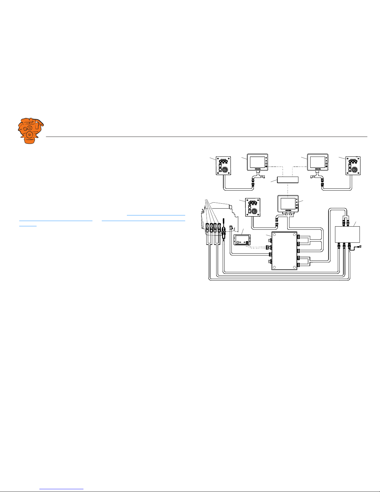
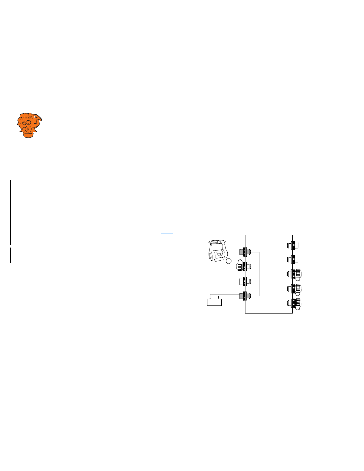
System overview
The images on this and the next page show the component parts of a control system
which is prepared for classification, and not prepared for classification, respectively.
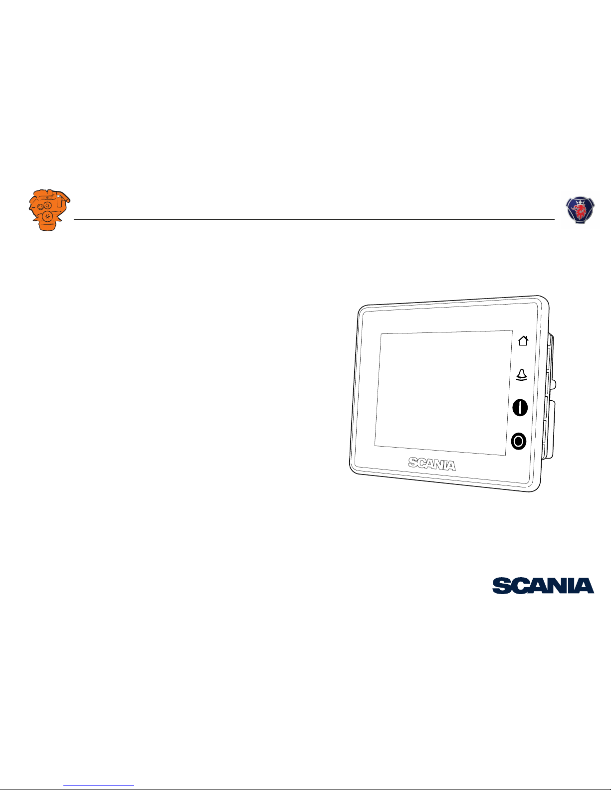
Main display (DCU)
The main display is the basic unit of the engine management system. Different sensor
values are displayed on the main display touch screen, and different commands are
also carried out there.
The main display is configured using a computer with a web browser via the built in
web server of the main display. This is described in the Configuring the main display
and connecting equipment, examples and Configuring the main display, detailed description sections.
Auxiliary display (RP)
The auxiliary display is an option and has the same user interface as the main display.
The auxiliary display reads the configuration from the main display. This makes it
easy to retrofit.
Control panel
The engine can be started and stopped through the control panel. It can also be used
to activate and adjust engine speed settings 1 or 2. The engine installation can be carried out with or without a control panel.
1
1
2
2
3
1
4
8
7
6
5
383 762
Example of the layout of a type approved control system.
1. Control panel (option).
2. Auxiliary display (RP, option).
3. Network switch (option).
4. Main display (DCU).
5. Safety module (SDU).
6. Junction box.
7. Gateway (option).
8. Monitors on the engine required for classification.
INSTALLATION
MANUAL
© Scania CV AB 2017, Sweden
System overview
03:04 Issue 2.0 en-GB 5
Network switch
A network switch is only required if more than one auxiliary display is connected to
the engine management system. If the system only contains one auxiliary display, it
is connected directly to the main display via a crossover network cable.
Safety module (SDU)
The safety device unit has monitoring and shutdown functions and is a requirement
for classified engine management systems. It should be easily accessible so that
alarms can be acknowledged in an easy way.
Junction box
The junction box is used to connect all the parts of the engine management system to
the engine. The junction box also contains fuses. It should be easily accessible.
Gateway
The gateway, which is an option, reads specific messages about position and speed
via NMEA 2000, so that the instrumentation can calculate fuel consumption per nautical mile. The gateway cannot process messages other than these.
1
2
1
3
5
4
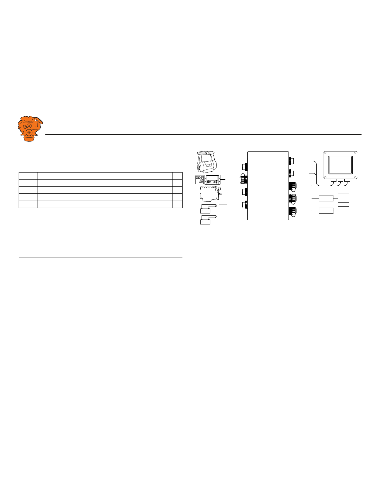
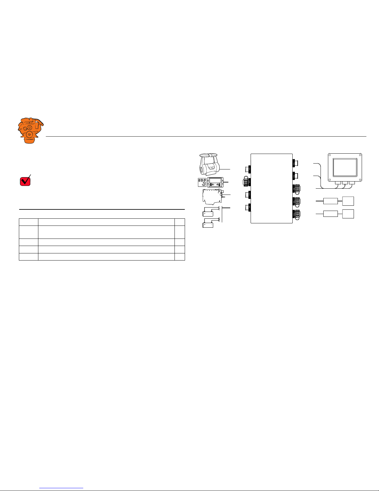
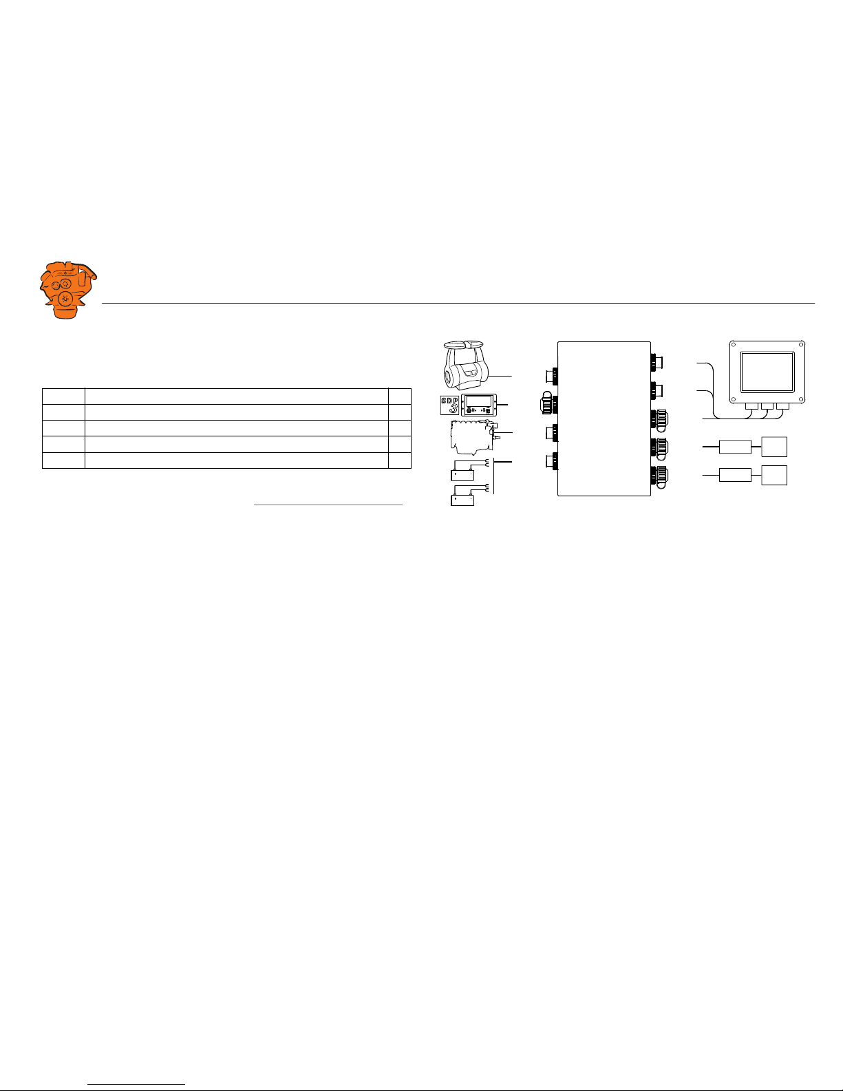
383 143
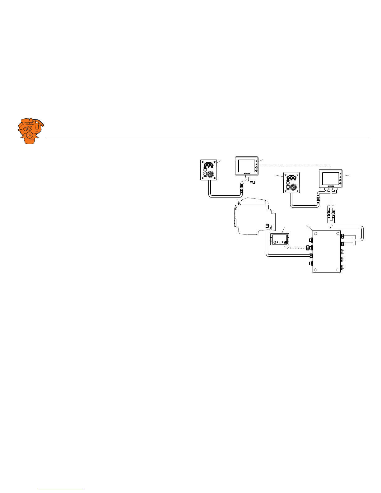
Example of the layout of a control system which is not prepared for classification, i.e.
a system without safety device units.
1. Control panel (option).
2. Auxiliary display (RP, option).
3. Main display (DCU).
4. Junction box.
5. Gateway (option)

INSTALLATION
MANUAL
© Scania CV AB 2017, Sweden
System overview
03:04 Issue 2.0 en-GB 6
Positioning of the displays
Do not position the displays so that they are exposed to direct sunlight. This impairs
the readability of the displays. The user should have full access to the displays. It
must also be easy to access the connections on the rear of the displays.
IMPORTANT!
The displays must not be fitted on vibrating equipment. They may only be positioned
next to the engine bed if either the engine or the display housing has vibration damping.
Main display
Scania recommends positioning the main display in the engine compartment for the
following reasons:
• To ensure that operation and monitoring are close to the engine.
• To minimise the lengths of the electrical cables between the sensors and main display.
• To reduce the risk of electrical interference caused by long electrical cables.
REQUIREMENT!
On a type approved installation, the main display must be located in the engine compartment.
Auxiliary display
The auxiliary display is normally positioned outside the engine compartment, but can
also be positioned in the engine compartment.
INSTALLATION
MANUAL
© Scania CV AB 2017, Sweden
System overview
03:04 Issue 2.0 en-GB 7
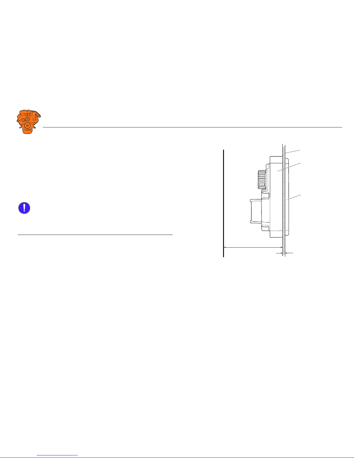
Installation
1. Make a rectangular hole where the display is to be fitted (1). The hole should be
153 mm wide and 121 mm high. There must be at least 85 mm free space (A) behind the display.
2. Position the display (2) in the hole.
3. Fit the mounting frame (3) with the accompanying screws.
The accompanying screws can be used if the thickness of the surface the display is
installed on (B) does not exceed 5 mm. Use the longer M3 screws for thicker surfaces.
IMPORTANT!
If screws other than the accompanying screws are used, the length must be adjusted
so that the screws go no further than 12 mm in the display screw holes. If the screws
go in further, this may damage the electronics.
1
A
B
2
3
383 764
Installation of the displays.

INSTALLATION
MANUAL
© Scania CV AB 2017, Sweden
Connection
03:04 Issue 2.0 en-GB 8
Connection
Electrical cables
To protect against electromagnetic interference, Scania recommends that all electrical cables within the system are twisted in pairs with 35-40 turns/m. This only applies
to external signal cables connected to the system.
IMPORTANT!
If a shielded electrical cable is used, the shielding should be connected to ground, not
to 0 V. Connect pin 3 in harness-to-harness connector C1 of the main display to
ground. See Main display (DCU), connections
. Only connect the shielding to one
end of the electrical cable.
To provide good separation of the electromagnetic interference that can occur, some
of the electrical cables can be routed separately from the others, e.g. the signal cable
from a magnetic pulse sensor. The electrical cables for the auxiliary display electric
power supply must have a cross-sectional area of at least 1.5 mm
2
and be connected
to a fuse of their own, powered directly from the battery. The main display receives
its electric power supply from the junction box.
Ground
IMPORTANT!
Separate ground and 0 V. In marine installations, ground and 0 V must not be connected. The hull is ground and the battery negative terminal is 0 V.
24 V and 0 V are filtered in the main display in order to reduce electromagnetic interference. If ground and 0 V are connected together, the filters in the main display
will not function.
INSTALLATION
MANUAL
© Scania CV AB 2017, Sweden
Connection
03:04 Issue 2.0 en-GB 9
Junction box, connection
Minimum connection
The minimum connection required for the system to function is for the pins on harness-to-harness connector C4066 to be connected.
Connecting the throttle control
Please refer to 03:01 Electrical system for information on how to connect the throttle
control to the engine control unit. If the throttle control is connected to the engine
control unit, secondary throttle control cannot be used.
If the throttle control is to be controlled via the main display, the following must be
connected:
Passive throttle control
Connect pins 1 and 2 in harness-to-harness connector C4068, according to C4068
.
Active throttle control
If active throttle control is to be connected, the throttle control must be grounded.
Bridge C4066 pin 2 and C4068 pin 3, and connect C4068 pin 3 to the electrical
ground point of the throttle control.
-
C4068-3
C4066-2
-
+
392 503
Connecting active throttle control.
INSTALLATION
MANUAL
© Scania CV AB 2017, Sweden
Connection
03:04 Issue 2.0 en-GB 10
C4066
Connection of power supply to the engine management system and instrumentation
2.1 (battery).
Note:
Connect the junction box directly to the battery and not to the starter motor. Use
twisted pair electrical cables and do not make the electrical cable longer than necessary. The cable cross-sectional area must be at least 2.5 mm².
If the system has a safety device unit (SDU), 2 separate groups of batteries must be
used. If the system does not have a safety device unit, pins 1-4 must be connected to
the same group of batteries.
C4062
Connection to engine harness-to-harness connector C4001.
Pin Description I/O
1 30 voltage, 24 V -
2 Ground (battery negative terminal) -
3 30 voltage, 24 V -
4 Ground (extra battery negative terminal) -
C4068
C4067
C4062
C4066
SDU
SDU
C4058
C4059
C4060
C4061
C4052
C4056
1
2
3
4
Gateway
C4001
C4053
DCU
393 368
Connecting the junction box.
INSTALLATION
MANUAL
© Scania CV AB 2017, Sweden
Connection
03:04 Issue 2.0 en-GB 11
C4067
Diagnostic socket for connecting e.g. SDP3 and CAN communication. Use harnessto-harness connector 1 508 055 and hand crimping tool 99 494.
REQUIREMENT!
Any equipment connected to the harness-to-harness connector must comply with the
CAN specification. 15 voltage must only be used for SDP3 and CAN communication.
Pin Description I/O
1 15 voltage: 24 V after fuse F4005 and relay in the junction box. Con-
trolled by the system being active.
-
2Ground -
3CAN High -
4CAN Low -
C4068
C4067
C4062
C4066
SDU
SDU
C4058
C4059
C4060
C4061
C4052
C4056
1
2
3
4
Gateway
C4001
C4053
DCU
393 368
Connecting the junction box.
INSTALLATION
MANUAL
© Scania CV AB 2017, Sweden
Connection
03:04 Issue 2.0 en-GB 12
C4068
Connecting the incoming throttle actuation signal. The update frequency is 100 Hz,
with a median filter on 3 readings.
C4052
Connection to main display via C1 and C2. See Main display (DCU), connections.
C4053
Connection to main display via C1.
C4056
Connection to main display via C1 and C3.
C4058
Connection to safety device unit (SDU) via C4060 (classified systems only).
C4059
Connection to safety device unit (SDU) via C4061 (classified systems only).
Pin Description I/O
1 24 V (0.2 A), voltage supply to passive throttle control O
2 Input for signal from passive throttle control, 4-20 mA I
3 Not used -
4 Not used -
C4068
C4067
C4062
C4066
SDU
SDU
C4058
C4059
C4060
C4061
C4052
C4056
1
2
3
4
Gateway
C4001
C4053
DCU
393 368
Connecting the junction box.
INSTALLATION
MANUAL
© Scania CV AB 2017, Sweden
Connection
03:04 Issue 2.0 en-GB 13
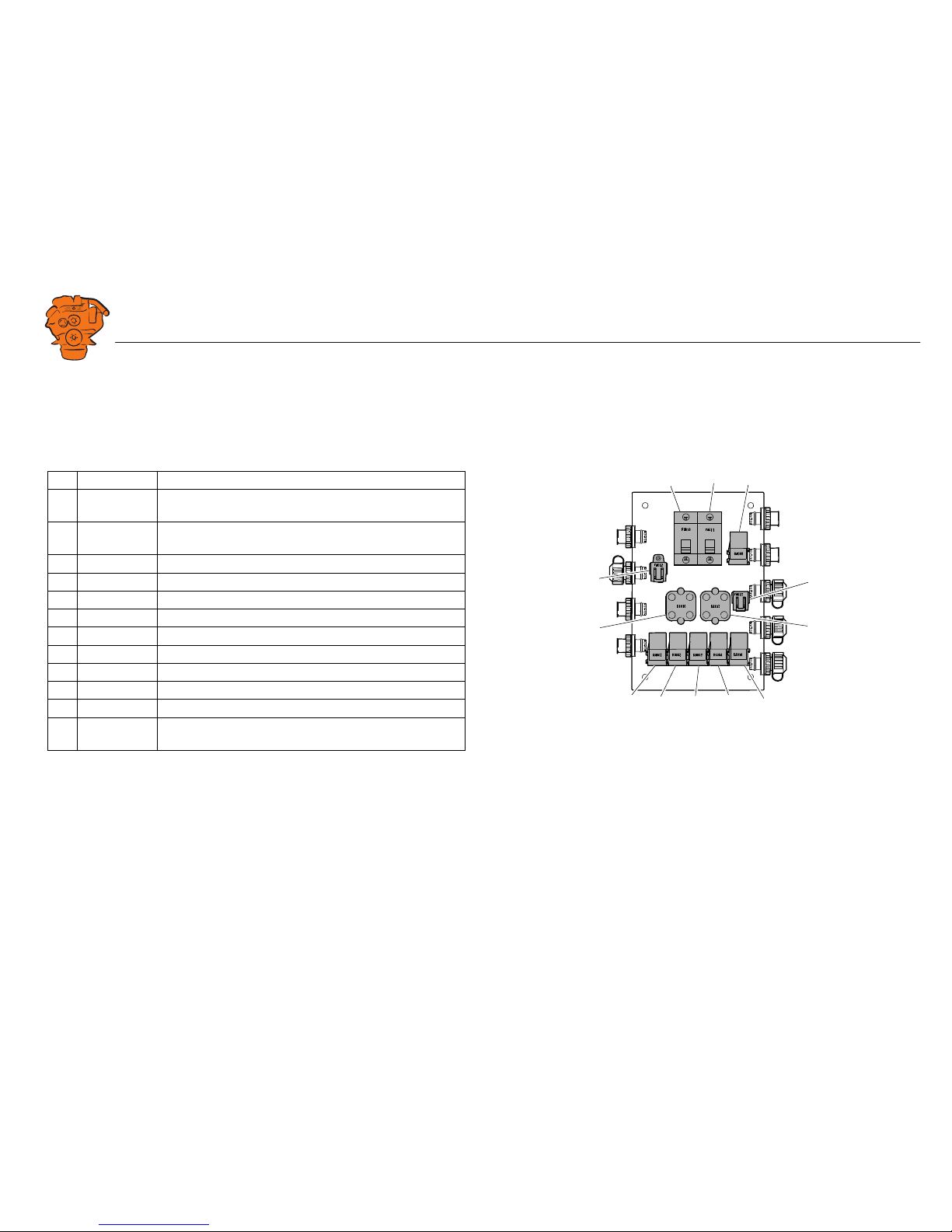
Junction box, components
There are two 20 A miniature circuit breakers in the junction box, one for each battery connection. Depending on the cable length, it may be necessary to fit extra fuses
for the electrical cable. The junction box also has a number of blade fuses, diodes and
relays as described below.
Designation Description
1 F4010 20 A miniature circuit breaker for incoming voltage from bat-
tery group, main supply
2 F4011 20 A miniature circuit breaker for incoming voltage from bat-
tery group, redundant supply
3 R4005 Relay for 15 voltage
4 F4013 2 x 2 A blade fuses for auxiliary socket
5 D4017 Diode to separate the battery groups, ground
6 D4018 Diode to request shutdown/activation of 15 voltage
7 R4004 Relay for engine shutdown (15 voltage)
8 R4003 Relay for engine shutdown (30 voltage)
9 R4002 Relay for detecting loss of redundant battery group
10 R4001 Relay for detecting loss of main battery group
11 D4016 Diode to separate the battery groups (30 voltage)
12 F4012 2 x 20 A blade fuses for engine control unit, 2 x 5 A blade
fuses for internal supply to panels
347 887
123
4
5
10
9876
12
11
Components in the junction box.
INSTALLATION
MANUAL
© Scania CV AB 2017, Sweden
Connection
03:04 Issue 2.0 en-GB 14
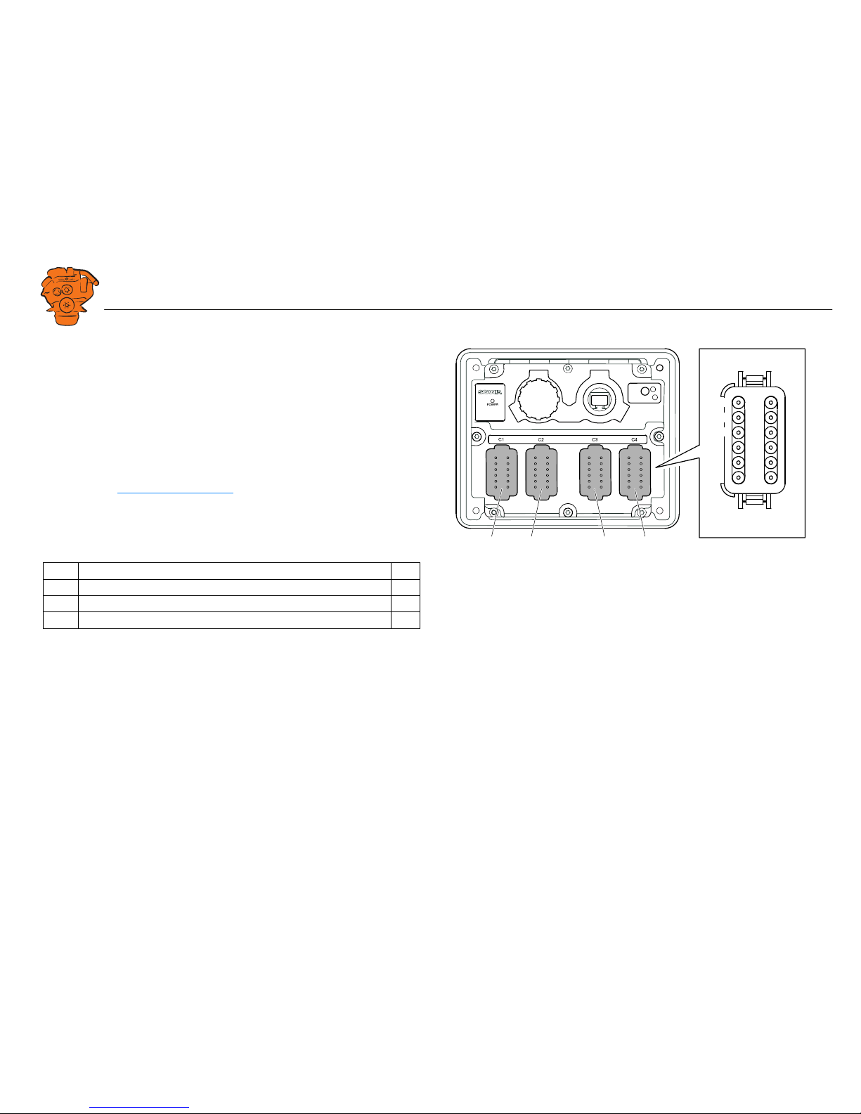
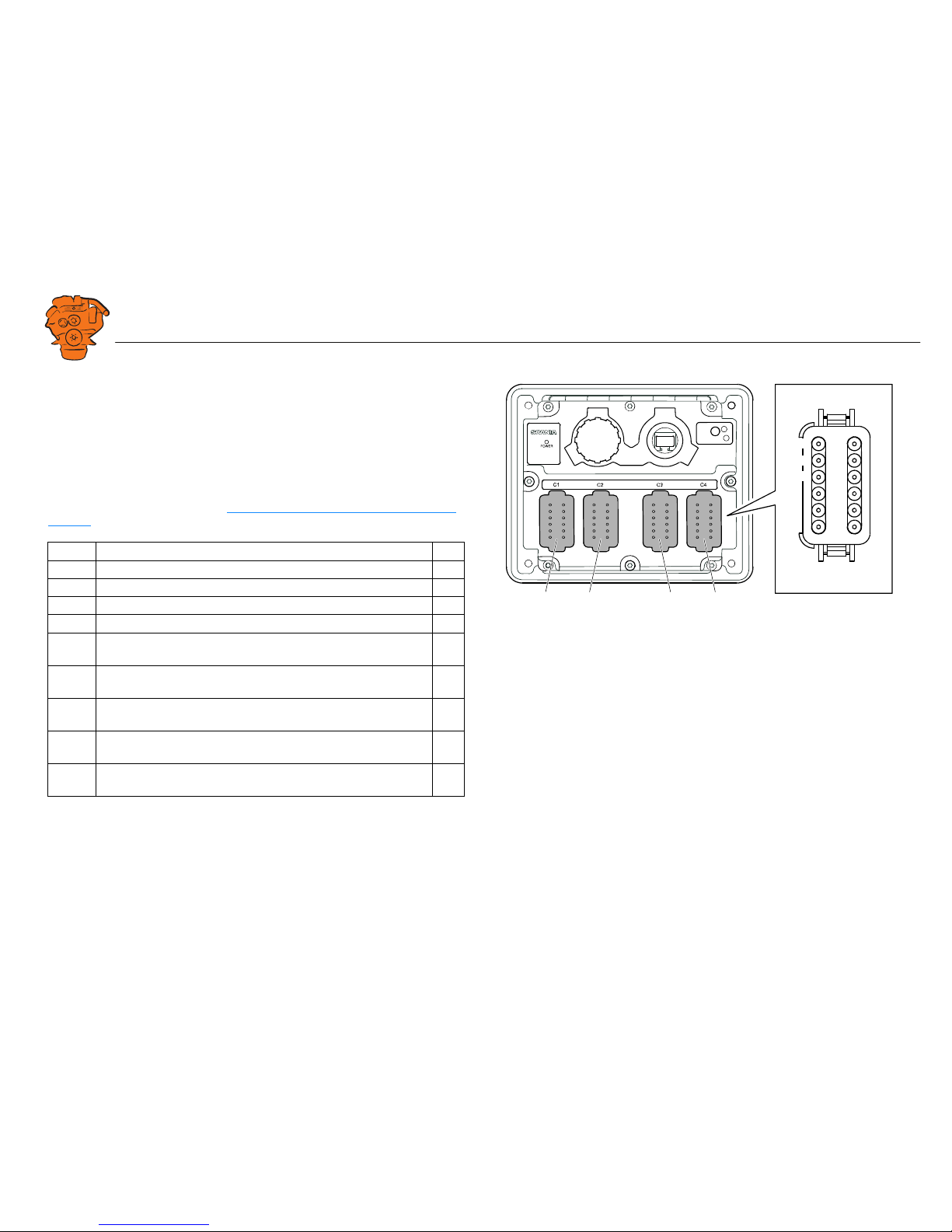
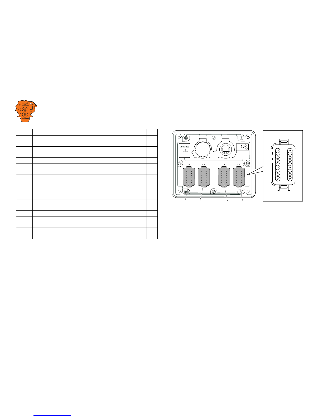
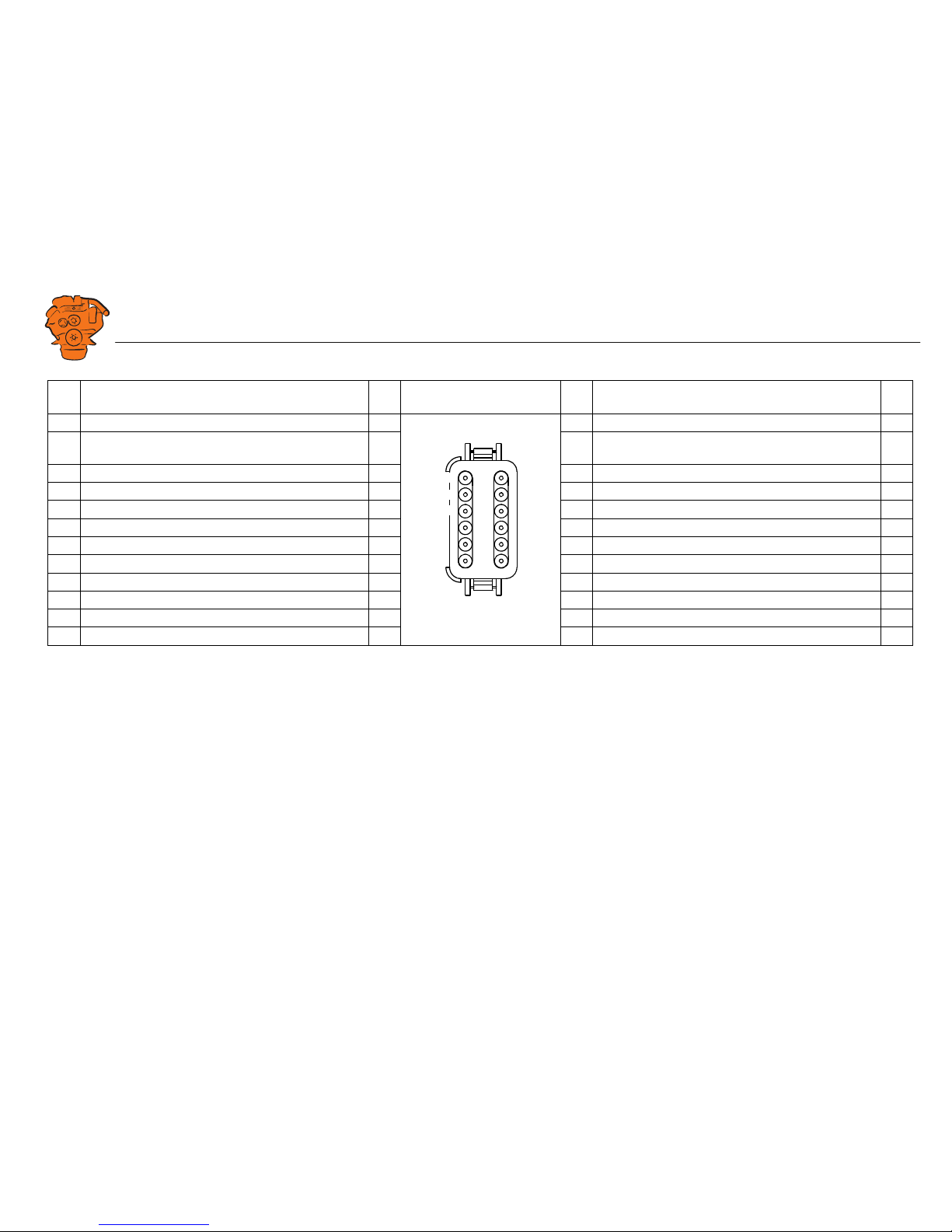
Main display (DCU), connections
The main display has 4 harness-to-harness connectors with 12 pins each: C1, C2, C3
and C4. Some of the pins are occupied by equipment and system functions. Others
can optionally be connected and configured.
The only connection needed for the system to work is for the main display harnessto-harness connectors C1, C2 and C3 to be connected to junction box harness-to-harness connectors C4052, C4053 and C4056.
On the following pages, the functions of all pins on main display harness-to-harness
connectors C1, C2, C3 and C4 are listed. The section below lists the pins according
to function. The Pin list in numerical order
section briefly lists the pins in numerical
order.
Pin list according to function
Power supply
The system is designed for a voltage of 24 V.
Alarm at low voltage
There is a 30 second delay before the alarm or warning is activated.
Information about voltage level can be found in Menu > Help > Troubleshooting >
Troubleshooting DCU > Supply. The supply voltage shown there applies to the main
display, not to the battery.
C1 Description I/O
11 24 V main power supply. I/O
12 0 V main power supply. I
3 Ground connection. I
Warning: < 21 V Alarm: < 18 V
C2 C3 C4C1
7
8
9
C1-C4
1
2
3
4
5
6
10
11
12
383 765
Main display harness-to-harness connectors. The pin numbering is shown as viewed
from the electrical cable input side.
INSTALLATION
MANUAL
© Scania CV AB 2017, Sweden
Connection
03:04 Issue 2.0 en-GB 15
J1939 CAN interface
The CAN connection of the main display to the engine control unit is via harness-toharness connector C1. The connection is terminated. CAN connection of other equipment occurs via harness-to-harness connector C2.
C1 Description I/O
7 CAN 1 high. I
8 CAN 1 low. I
9 CAN 1 shielding. I
C2 Description I/O
10 CAN 2 high. Can also be configured as flexible I/O #20. Can only be
configured as a digital signal in.
I
11 CAN 2 low. Can also be configured as flexible I/O #21. Can only be
configured as a digital signal in.
I
12 CAN 2 shielding. Can also be configured as flexible I/O #5 or 0 V ref-
erence.
I
C2 C3 C4C1
7
8
9
C1-C4
1
2
3
4
5
6
10
11
12
383 765
Main display harness-to-harness connectors. The pin numbering is shown as viewed
from the electrical cable input side.

INSTALLATION
MANUAL
© Scania CV AB 2017, Sweden
Connection
03:04 Issue 2.0 en-GB 16
Relay for all faults
Every new event is counted as a fault in the alarm list, except diagnostics messages
with a white ranking. The relay can be used to switch on an external lamp or emit an
acoustic signal, for example.
Relay #1
The relay can be configured so that it is activated for any of the built in functions. See
the Relay Functions
section.
Relay #2
The relay can be configured so that it is activated for any of the built in functions. See
the Relay Functions
section.
C2 Description I/O
1 NC (1 A) Closed when the display is switched of or in the event of an
active fault.
-
2C (1 A) -
3 NO (1 A). Closed when there are no active faults. -
C2 Description I/O
4NC (1 A) -
5C (1 A) -
6NO (1 A) -
C2 Description I/O
7NC (1 A) -
8C (1 A) -
9NO (1 A) -
C2 C3 C4C1
7
8
9
C1-C4
1
2
3
4
5
6
10
11
12
383 765
Main display harness-to-harness connectors. The pin numbering is shown as viewed
from the electrical cable input side.
INSTALLATION
MANUAL
© Scania CV AB 2017, Sweden
Connection
03:04 Issue 2.0 en-GB 17
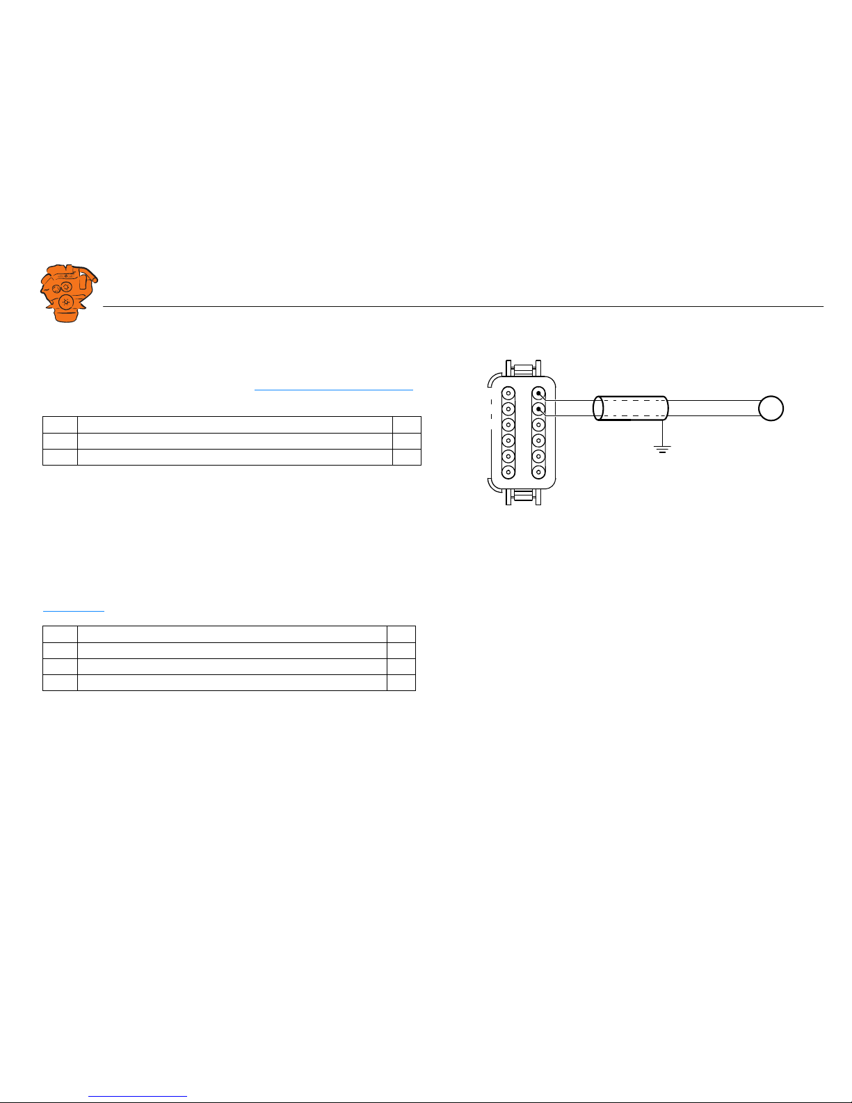
Input for magnetic pulse sensor
An auxiliary rotational speed sensor is connected here. Only connect electrical cable
shielding on the sensor side, or use an electrical cable twisted in pairs with 35-40
turns/m. An example of the connection is in the Connecting a magnetic pulse sensor
section.
Modbus RTU, RS-485
The main display has a built-in Modbus
TM
interface, on both RS-485 and Ethernet.
The latter can also be designated Modbus TCP. Information on configuration is in the
Modbus RTU
section.
C4 Description I/O
1A I
2 B. Can also be configured as flexible I/O #18 or as 0 V reference. I
C4 Description I/O
3 Shielding I
4Low I
5High I
0V reference
Pickup
C4
7
8
9
1
2
3
4
5
6
10
11
12
383 966
Connection of magnetic pulse sensor. The pin numbering is shown as viewed from the
electrical cable input side.
INSTALLATION
MANUAL
© Scania CV AB 2017, Sweden
Connection
03:04 Issue 2.0 en-GB 18
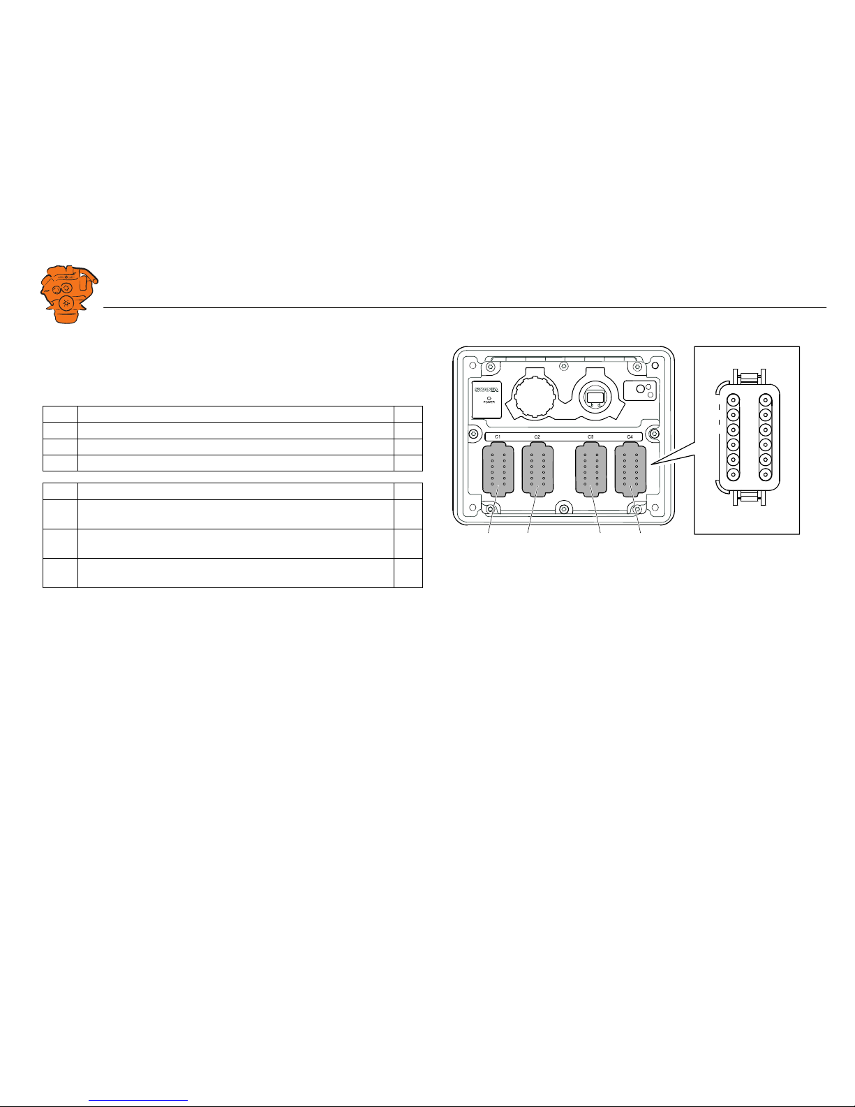
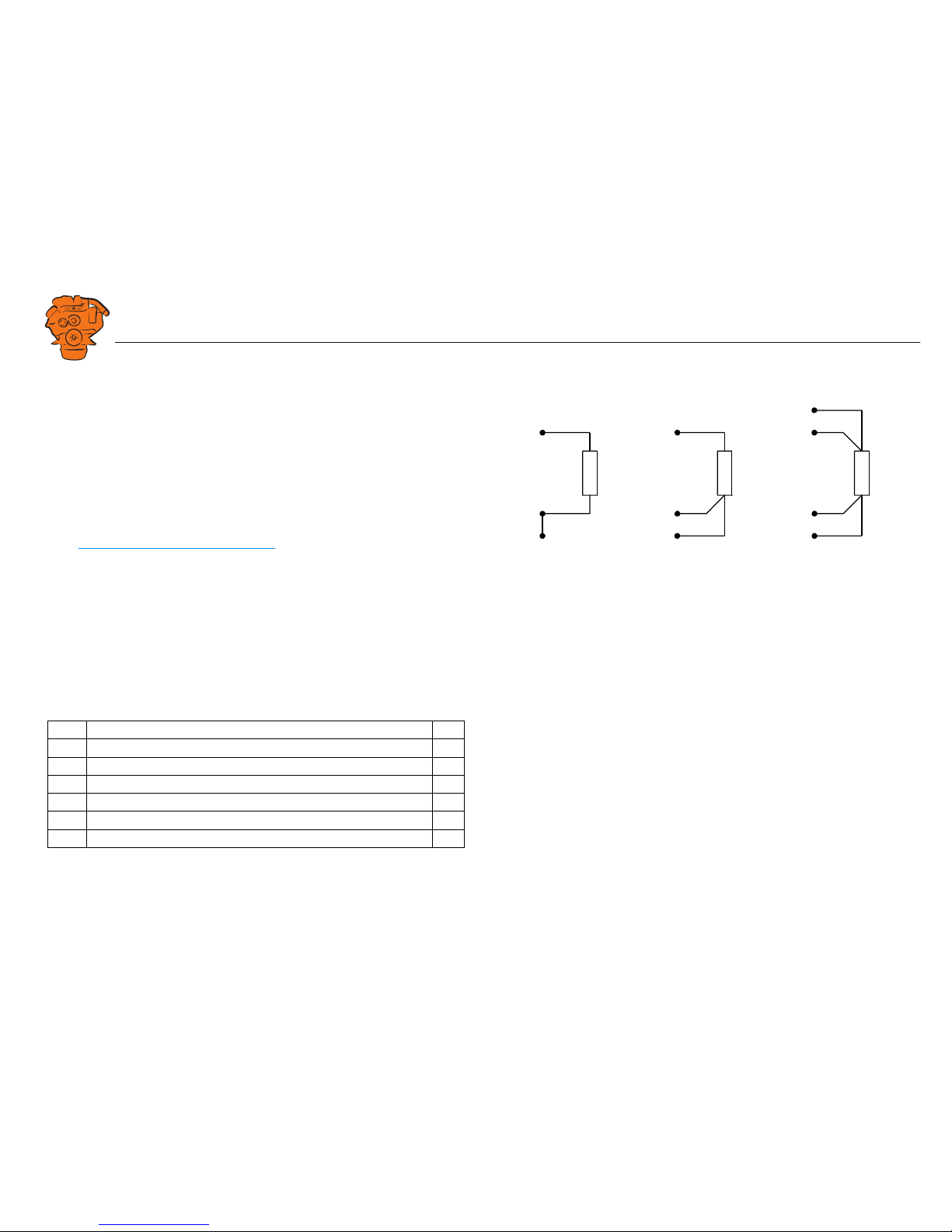
Inputs for PT100 temperature sensor
There are 2 inputs for temperature sensors in the main display. The inputs are adapted
for PT100 sensors with 2, 3 or 4 electrical cables. Connect the electrical cables as follows:
2 wire PT100: Bridge A and B. Connect one wire to AB and the other to C.
3 wire PT100: Connect A to A, B to B and C to C.
4 wire PT100: Connect in the same way as 3 filament PT100, but note that the fourth
wire, D, should not be connected. It should hang loose or, if necessary, be cut off.
In the Connecting a PT100 temperature sensor
section there is an example of the con-
nection and configuration of a PT100 sensor.
If the signal is outside the following limit values, a warning is displayed on the display:
The updating frequency is 2 Hz.
Below 90
ohms
short circuit
Above 390
ohms
defective
C4 Description I/O
6 PT100 #1 A I
7 PT100 #1 B I
8 PT100 #1 C I
9 PT100 #2 A I
10 PT100 #2 B I
11 PT100 #2 C I
B
C
A
1
B
C
A
2
B
C
A
3
383 968
Connection of
1. 2 wire PT100.
2. 3 wire PT100.
3. 4 wire PT100.
INSTALLATION
MANUAL
© Scania CV AB 2017, Sweden
Connection
03:04 Issue 2.0 en-GB 19
Flexible connections
The main display has 19 flexible connections. If CAN 2 is not used, there are two further flexible connections, #20–21, for digital signal in.
The flexible connections can be configured to be used for voltage supply or as inputs
and outputs for optional functions or events. If the system has a control panel, flexible connections #7 to #11 are reserved for the control panel.
Examples of the configuration of the flexible connections and connection of sensors
and micro switches are given in the Examples of connection of sensors and micro
switches section.
Pin Description I/O
C1-1 Flexible I/O #1. I/O
C1-2 Flexible I/O #2. Can also be configured as 0 V reference. I/O
C1-4 Flexible I/O #3. I/O
C1-10 Flexible I/O #4. I/O
C2-12 Flexibel I/O #5. Can also be configured as CAN 2 shielding or 0 V
reference.
I/O
C3-1 Flexible I/O #6. Can also be configured for 0-5 V voltage supply to
sensor.
I/O
C3-2 Flexible I/O #7. Reserved in systems with control panel (engine
speed setting 1).
I/O
C3-3 Flexible I/O #8. Reserved in systems with control panel (engine
speed setting 2).
I/O
C3-4 Flexible I/O #9. Reserved in systems with control panel (engine
speed setting off).
I/O
C2 C3 C4C1
7
8
9
C1-C4
1
2
3
4
5
6
10
11
12
383 765
Main display harness-to-harness connectors. The pin numbering is shown as viewed
from the electrical cable input side.
INSTALLATION
MANUAL
© Scania CV AB 2017, Sweden
Connection
03:04 Issue 2.0 en-GB 20
Pin Description I/O
C3-5 Flexible I/O #10. Reserved in systems with control panel (15 volt-
age).
I/O
C3-6 Flexible I/O #11. Reserved in systems with control panel (engine
start).
I/O
C3-7 Flexible I/O #12. Can also be configured as 0 V reference. I/O
C3-8 Flexible I/O #13. Can also be configured for 0-5 V voltage supply
to sensor.
I/O
C3-9 Flexible I/O #14. I/O
C3-10 Flexible I/O #15. I/O
C3-11 Flexible I/O #16. I/O
C3-12 Flexible I/O #17. I/O
C4-2 Flexibel I/O #18. Can also be configured as input for magnetic
pulse sensor B or 0 V reference.
I/O
C4-12 Flexible I/O #19. I/O
C2-10 Flexible I/O #20. Digital signal in only. Can also be configured for
CAN 2 high.
I
C2-11 Flexible I/O #21. Digital signal in only. Can also be configured for
CAN 2 low.
I
C2 C3 C4C1
7
8
9
C1-C4
1
2
3
4
5
6
10
11
12
383 765
Main display harness-to-harness connectors. The pin numbering is shown as viewed
from the electrical cable input side.
INSTALLATION
MANUAL
© Scania CV AB 2017, Sweden
Connection
03:04 Issue 2.0 en-GB 21
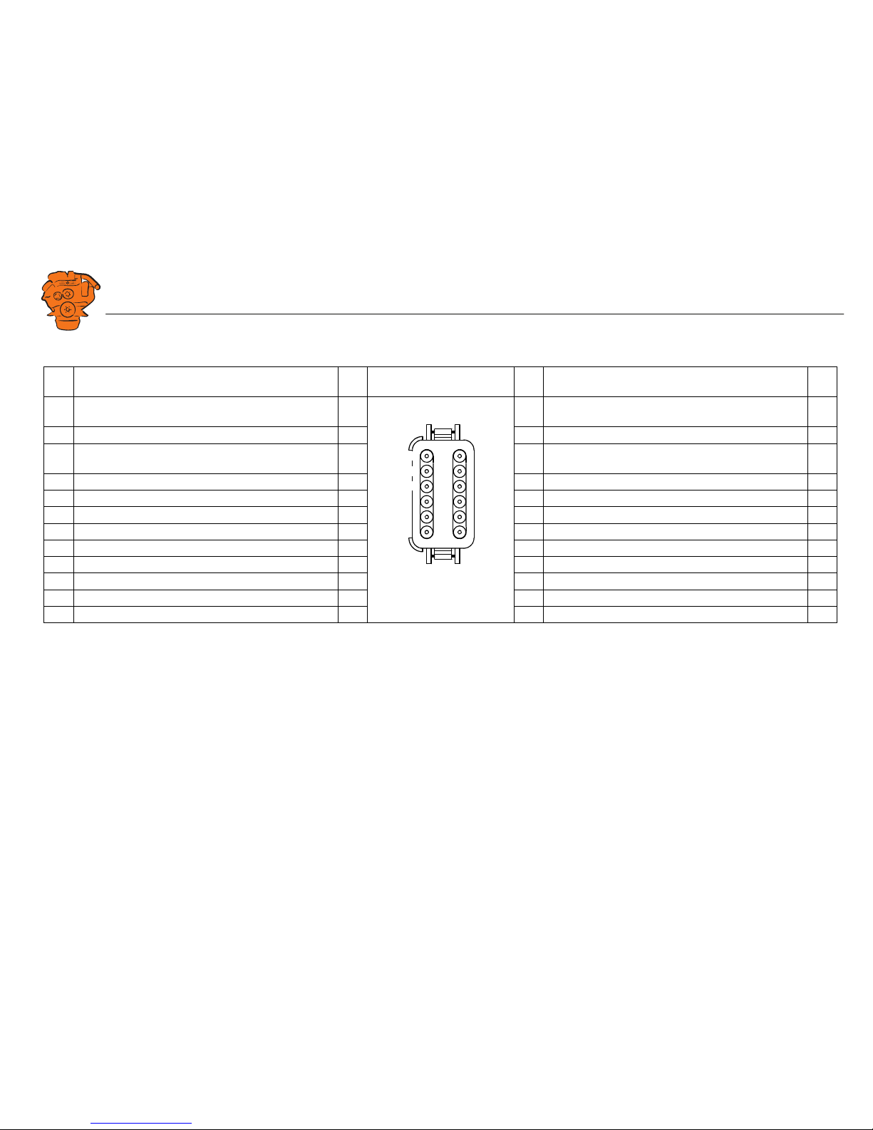
Pin list in numerical order
C1 Description I/O C1-C4 viewed from the elec-
trical cable input side.
C2 Description I/O
1 Flexible I/O #1. I/O 1 Relay for all faults, NC (1 A). Closed when the display is
switched of or in the event of an active fault.
-
2 Flexible I/O #2 or 0 V reference. I/O 2 Relay for all faults, C (1 A). -
3 Ground connection. I 3 Relay for all faults, NO (1 A). Closed when there are no
active faults.
-
4 Flexible I/O #3. I/O 4 Relay #1, NC (1 A). -
5 RIO link low. Not used. I 5 Relay #1, C (1 A). -
6 RIO link high. Not used. I 6 Relay #1, NO (1 A). -
7 CAN 1 high. The connection is terminated. I 7 Relay #2, NC (1 A). -
8 CAN 1 low. The connection is terminated. I 8 Relay #2, C (1 A). -
9 CAN 1 shielding. The connection is terminated. I 9 Relay #2, NO (1 A). -
10 Flexible I/O #4. I/O 10 CAN 2 high or flexible I/O #20. Digital signal in only. I
11 24 V main power supply. I/O 11 CAN 2 low or flexible I/O #21. Digital signal in only. I
12 0 V main power supply. I 12 CAN 2 shielding, 0 V reference or flexible I/O #5. I
7
8
9
C1-C4
1
2
3
4
5
6
10
11
12
INSTALLATION
MANUAL
© Scania CV AB 2017, Sweden
Connection
03:04 Issue 2.0 en-GB 22
C3 Description I/O C1-C4 viewed from the elec-
trical cable input side.
C4 Description
1 Flexible I/O #6 or 0–5 V voltage supply for sensor. I/O 1 Magnetic pulse sensor A. I
2 Flexible I/O #7. Reserved in systems with control panel. I/O 2 Magnetic pulse sensor B, flexible I/O #18 or 0 V refer-
ence.
I
3 Flexible I/O #8. Reserved in systems with control panel. I/O 3 Modbus RTU shielding. I
4 Flexible I/O #9. Reserved in systems with control panel. I/O 4 Modbus RTU low. I
5 Flexible I/O #10. Reserved in systems with control panel. I/O 5 Modbus RTU high. I
6 Flexible I/O #11. Reserved in systems with control panel. I/O 6 PT100 #1 A. I
7 Flexible I/O #12 or 0 V reference. I/O 7 PT100 #1 B. I
8 Flexible I/O #13. I/O 8 PT100 #1 C. I
9 Flexible I/O #14. I/O 9 PT100 #2 A. I
10 Flexible I/O #15. I/O 10 PT100 #2 B. I
11 Flexible I/O #16. I/O 11 PT100 #2 C. I
12 Flexible I/O #17. I/O 12 Flexible I/O #19. I/O
7
8
9
C1-C4
1
2
3
4
5
6
10
11
12
INSTALLATION
MANUAL
© Scania CV AB 2017, Sweden
Connection
03:04 Issue 2.0 en-GB 23
Auxiliary display (RP), connections
Power supply
The auxiliary display must have a separate electric power supply. The system is designed for a voltage of 24 V.
Note:
Connect the display directly to the battery and not to the starter motor. Use twisted
pair electrical cables and do not make the electrical cables longer than necessary. The
cable cross-sectional area must be at least 1.5 mm².
Scania recommends connecting the auxiliary display to the same fuse group as the
main display. Avoid connecting other electrical consumers to the same electrical cable, as it can interfere with the equipment.
Alarm at low voltage
There is a 30 second delay before an alarm or warning is activated.
Information about voltage level can be found in Menu > Help > Troubleshooting >
General in the auxiliary display. The supply voltage shown there applies to the auxiliary display, not to the battery.
C1 Description I/O
3 Ground connection I
11 24 V main power supply I/O
12 0 V main power supply I
Warning: < 21 V Alarm: < 18 V
C2 C3 C4C1
7
8
9
C1-C4
1
2
3
4
5
6
10
11
12
383 765
Auxiliary display harness-to-harness connectors. The pin numbering is shown as
viewed from the electrical cable input side.

INSTALLATION
MANUAL
© Scania CV AB 2017, Sweden
Connection
03:04 Issue 2.0 en-GB 24
Relay for all faults
Every new event is counted as a fault in the alarm list, except diagnostics messages
with a white ranking.
Connection of control panel
C2 Description I/O
1 NC (1 A) Closed when the display is switched of or in the event of an
active fault.
-
2C (1 A) -
3 NO (1 A). Closed when there are no active faults. -
C3 Description I/O
2 Engine speed setting 1. I
3 Engine speed setting 2. I
4 Deactivation of the engine speed setting. I
5 15 voltage. I
6 Engine start. I
C2 C3 C4C1
7
8
9
C1-C4
1
2
3
4
5
6
10
11
12
383 765
Auxiliary display harness-to-harness connectors. The pin numbering is shown as
viewed from the electrical cable input side.
INSTALLATION
MANUAL
© Scania CV AB 2017, Sweden
Connection
03:04 Issue 2.0 en-GB 25
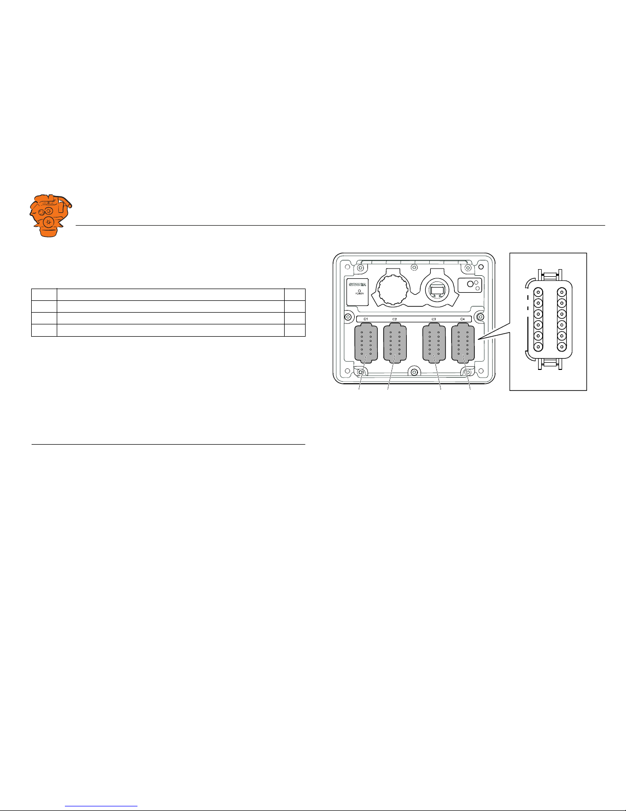
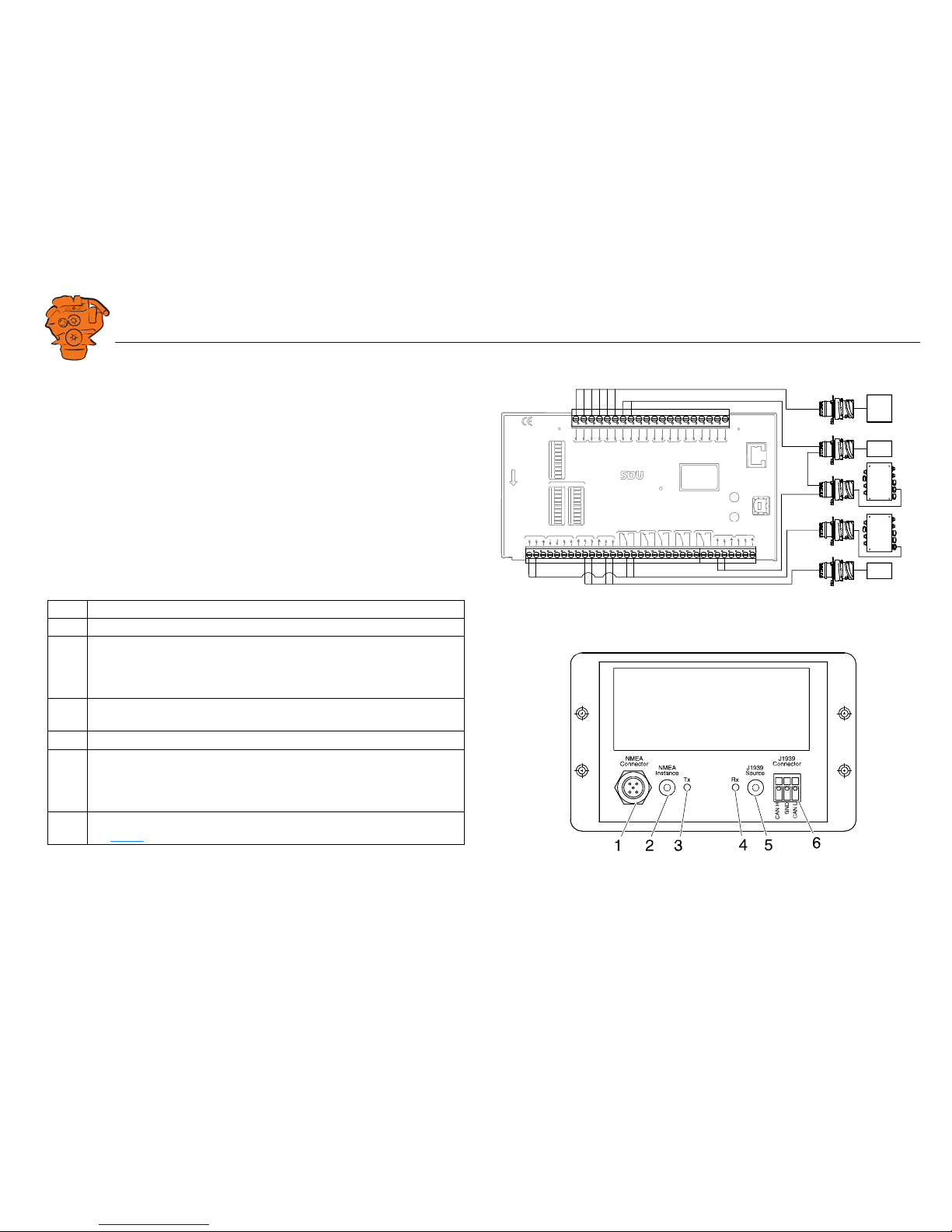
Safety module (SDU), connection
The illustration shows the safety device unit connections.
Gateway – overview
Description
1 Connection to the ship NMEA 2000 network.
2 NMEA Instance rotary control. Set the instance which the gateway trans-
mits to other units. Used if 2 or more gateways are connected to the same
NMEA 2000 network. In such a case, make sure that each gateway has a
unique instance, e.g. "0" and "1".
3 Blue Tx LED, indicates that data is being received from NMEA 2000 every
2.5 seconds.
4 Green Rx LED, indicates that data is being sent to J1939.
5 J1939 Source rotary control. Set the instance for the NMEA 2000-GPS
which the information should be loaded from. If the gateway does not receive any signals from a GPS with the selected instance within 30 seconds,
all valid GPS data is transferred automatically.
6 Connection to harness-to-harness connector C4067 junction box.
See C4067
.
SWITCH 1
SWITCH 2
SWITCH 3
SWITCH 4
SWITCH 5
SWITCH 6
SWITCH 7
SWITCH 8
SWITCH 1
SWITCH 2
SWITCH 3
SWITCH 4
SWITCH 5
SWITCH 6
SWITCH 7
SWITCH 8
SHUTDOWNFA
ULT
SWITCH 1
SWITCH 2
SWITCH 3
SWITCH 4
SWITCH 5
SWITCH 6
SWITCH 7
SWITCH 8
STATUS
POWER
CR
ANK CUTOFF
R
UNNING
TACHO 1
TACHO 2
SHUTDOWN OVERRIDE
B
UZZER
C
OM 1
C
OM 2
C
OM 3
SHUTDOWN
O
VERRIDE
A
CKNOWLEDGE
C
OM 3
C
ONFIGURATION
E
THERN
ET
shutdo
wn unit
RELEASE
SHUTDOWN
O
VERSPEED
SHUTD
O
WN COIL
SHUTDOWN OVERIDE
SHUTDOWN
CR
ANK
CUTOFFBUZZLERFAULTRUNNING
COM 1
DCU LINK
COM 2
RS 485
MODBUS RTU
ACKNOWLEDGE
OVERSPEED
TEST
C
OM 4
USB
TACHO 2
TACHO 1
S
H
U
T
D
O
W
N
C
O
I
L
S
U
P
P
L
Y
1 24V
4 24V
6 24V
20V
70V
50V38
34353637383940414243421
422
423
424
425
42650515253
9101112131415161718192021222324252627282930313233
H
L
H
L
C4063
T4003
T4004
C4064
C4074
C4060
C4061
C4065
T4005
T4006
T4007
C4058
C4059
383 767
361 902
INSTALLATION
MANUAL
© Scania CV AB 2017, Sweden
Connection
03:04 Issue 2.0 en-GB 26
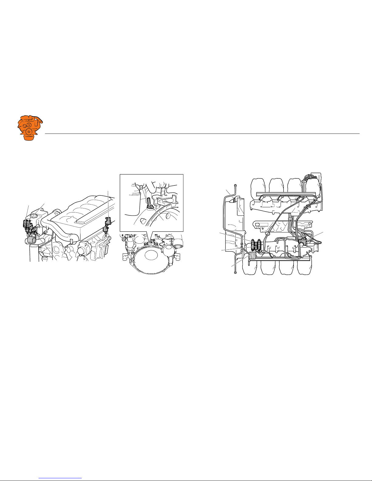
Position of the monitors on the engine
See 02:01 Engine for information on where to connect external monitoring sensors.
DI13 DI16
T4003: Oil pressure monitor.
T4004: Coolant temperature monitor.
T4005: Engine speed monitor.
T4006: Coolant pressure monitor.
T4007: Fuel pressure monitor.
T4007
T4006
T4004
T4003
T4005
386 380
T4005
T4003
T4004
T4006
T4007
386 381
INSTALLATION
MANUAL
© Scania CV AB 2017, Sweden
Connection
03:04 Issue 2.0 en-GB 27
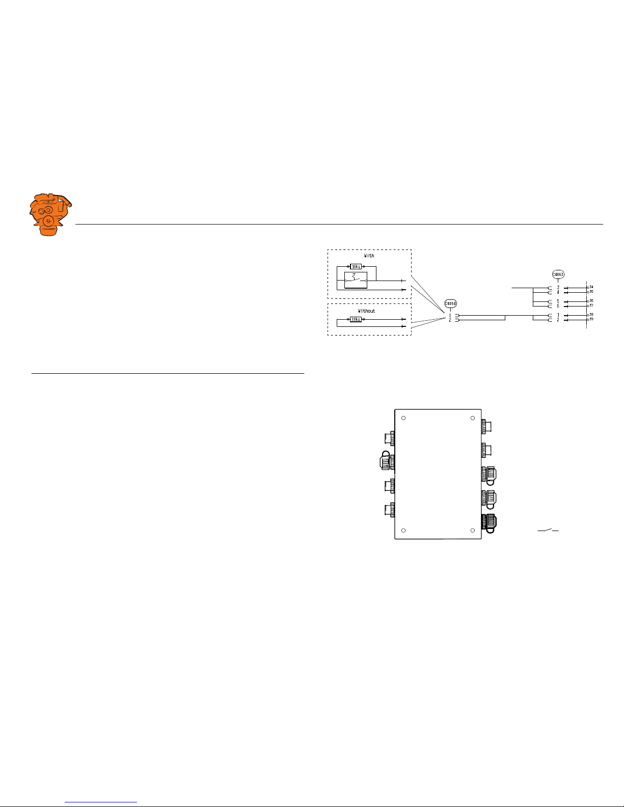
Connecting emergency stop
It is possible to connect an emergency stop which disconnects the voltage to the engine control unit. The connection is made in different ways, depending on whether
the system has a safety device unit (SDU) or not.
System with safety device unit (SDU)
Connect a switch with a 10 kohms resistor to harness-to-harness connector C4064 in
cable harness connected to the safety device unit.
Note:
The resistor must be connected even when there is no emergency stop. Otherwise, a
fault code is generated.
System without safety device unit (SDU)
Connect a regular open switch to pin 3 in harness-to-harness connector C4059 in the
junction box. The switch must be connected to 24 V from the same group of batteries
as the junction box.
Use connector 2 131 199 and the following tools:
• Hand crimping tool 99 494
• Hand crimping tool 99 491
347 885
SDU
System with safety device unit: connection of emergency stop to C4064.
+24V
C4059-3
347 886
System without safety device unit: connecting an emergency stop to the junction box.
INSTALLATION
MANUAL
© Scania CV AB 2017, Sweden
Connection
03:04 Issue 2.0 en-GB 28
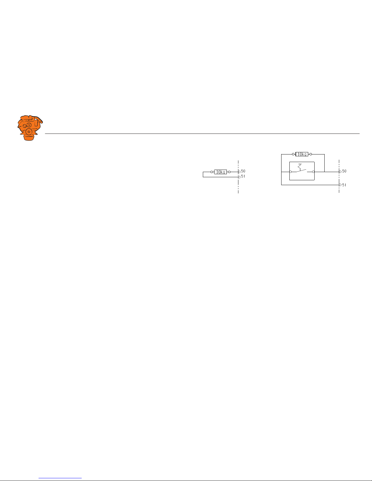
Engine shutdown override in systems with safety
device unit (SDU)
It is possible to override engine shutdown requested by the safety device unit in systems prepared for classification. Proceed as follows:
1. Remove the existing 10 kohms resistor between junction blocks 50 and 51 in the
safety device unit.
2. Connect a switch with a 10 kohms resistor between junction blocks 50 and 51.
SDU
347 888
SDU
12
Overriding engine shutdown requested by the safety device unit.
INSTALLATION
MANUAL
© Scania CV AB 2017, Sweden
Using the main display
03:04 Issue 2.0 en-GB 29
Using the main display
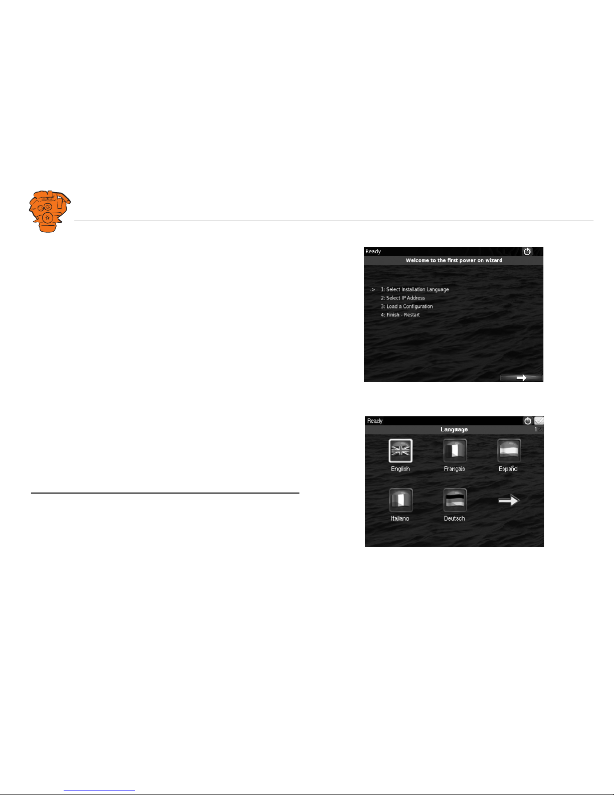
First start
When you start the main display for the first time or have performed a factory reset,
a power-on wizard is displayed. All settings made in the wizard can also be made at
a later stage. The first power-on wizard contains the following steps:
1.Select Installation Language
Select the language that should be used during the installation. There are 3 pages of
language options.
Note:
In this installation manual, all buttons and options are in English.
383 769
72 513
INSTALLATION
MANUAL
© Scania CV AB 2017, Sweden
Using the main display
03:04 Issue 2.0 en-GB 30
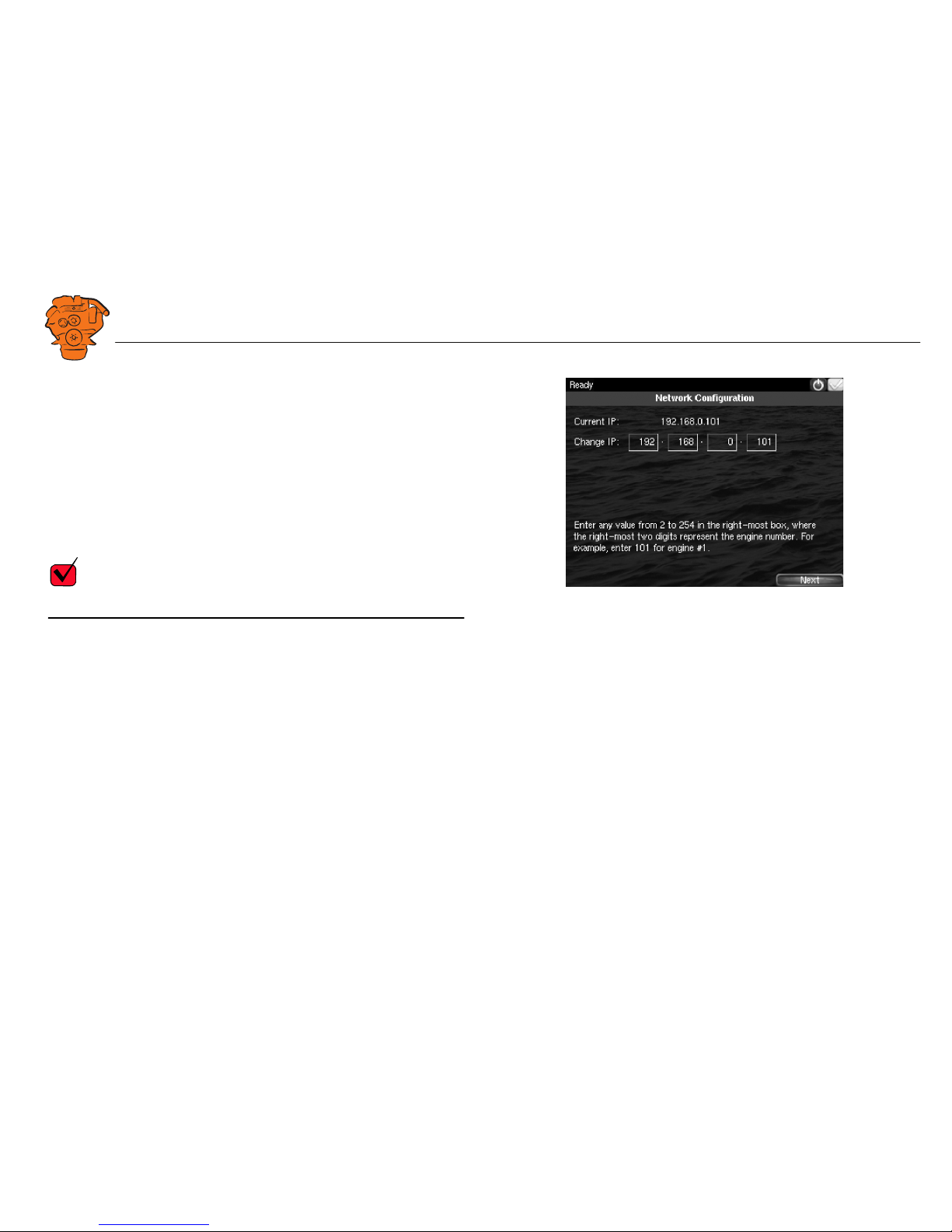
2.Select IP number
Enter an IP address. The IP address in the factory settings is 192.168.0.101.
The last 2 numbers in the main display's IP address are displayed as the engine number in the auxiliary display. Examples:
• 192.168.0.101 is displayed in the auxiliary display as Engine #1.
• 192.168.0.104 is displayed in the auxiliary display as Engine #4.
The main display IP address can be changed at a later stage. This is done via Short-
cuts > Menu > Settings > Administration > Network Configuration in the main display.
REQUIREMENT!
The last numeral in the IP address must always be unique to the network.
372 514
 Loading...