

Page 1
Operator's Manual
DI9, DC9 with DEC2
Industrial engine
opm96-9adec en 1 588 889
2003-10:1
Industrial & Marine Engines
IMPORTANT INFORMATION
When working on the engine, for example adjusting drive belts, changing the oil or adjusting the
clutch, it is important not to start the engine. The engine may be damaged and there is
SERIOUS RISK OF INJURY.
For this reason, always secure the starting device or disconnect a battery cable before working on
the engine. This is especially important if the engine has a remote starter or automatic starting.
This warning symbol and text is reproduced beside those maintenance points where it is
especially important to consider the risk of injury.
!
COMMISSIONING REPORT - WARRANTY
When the commissioning report has been filled in and sent to Scania, you have a 1-year warranty from the date
of commissioning.
Also fill in the particulars below as this can make things easier if you need to contact for example a service
workshop.
Engine number
Commissioning date
User's name and address
Signature
Engine type
Variant
Engine type and variant are indicated on the engine type plate
Page 2
2 © Scania Industrial & Marine Engines 2003-10:1
PREFACE
This Operator's Manual describes the handling and maintenance of Scania
DC9 and DI9 Industrial Engines with DEC2.
The engines are of direct-injection, liquid-cooled, four-stroke, 6-cylinder inline diesel type. These engines have turbochargers and charge air coolers: see
page 10.
Common applications are as power units in construction machines, generator
sets, earth-moving, railway and forestry machines as well as in irrigation
systems.
The engines can have different output and speed settings.
The normal output setting of the engine (performance code) is indicated on
the type plate, see page 10.
Note: Only standard components are described in the Operator's
Manual. Regarding special equipment, refer to the instructions of
the relevant manufacturer.
In order to obtain the best value and service life from your engine, there are
several points you should bear in mind:
- Read the manual before starting to use the engine. Even though you may
be experienced with Scania engines you may find new information in
this Operator's Manual.
- Follow the maintenance instructions. Good working order and service
life are ensured if maintenance is carried out according to the
instructions.
- In particular, read the safety information starting on page 6.
- Get to know your engine so that you know what it can do and how it
works.
- Whenever necessary, always contact an authorised Scania workshop.
They have special tools, genuine Scania parts and staff with training and
practical experience of Scania engines.
Note: Always use genuine Scania parts during service and repair so as
to keep your engine in the best possible working order.
The information in this manual was correct at the time of going to press.
However, we reserve the right to make alterations without prior notice.
Scania CV AB
Industrial and Marine Engines
S-151 87 Södertälje, Sweden
During the warranty period,
only genuine Scania parts may
be used during service and
repair otherwise the warranty
will be invalidated.
Page 3

2003-10:1 © Scania Industrial & Marine Engines 3
CONTENTS
PREFACE . . . . . . . . . . . . . . . . . . . . . . . . . . . . 2
ENVIRONMENTAL RESPONSIBILITY . . . . . .4
CERTIFIED ENGINES . . . . . . . . . . . . . . . . . . . .5
SAFETY INFORMATION . . . . . . . . . . . . . . . . . .6
Safety precautions for running the engine . . . . 7
Safety precautions for handling materials . . . . .8
Safety precautions for care and maintenance . . 8
TYPE DESIGNATIONS . . . . . . . . . . . . . . . 10
DEC2 CONTROL SYSTEM . . . . . . . . . . . . 12
STARTING AND RUNNING . . . . . . . . . . . 19
AT FIRST START . . . . . . . . . . . . . . . . . . . . . . .19
CHECKS BEFORE RUNNING . . . . . . . . . . . . .21
STARTING THE ENGINE . . . . . . . . . . . . . . . .21
At temperatures below 0°C: . . . . . . . . . . . . . .22
DRIVING . . . . . . . . . . . . . . . . . . . . . . . . . . . . . .23
Rotation speed . . . . . . . . . . . . . . . . . . . . . . . . .23
Coolant temperature . . . . . . . . . . . . . . . . . . . .23
Oil pressure . . . . . . . . . . . . . . . . . . . . . . . . . . .24
STOPPING THE ENGINE . . . . . . . . . . . . . . . . .24
Clutch . . . . . . . . . . . . . . . . . . . . . . . . . . . . . . .25
CHECKS AFTER RUNNING . . . . . . . . . . . . . .25
MAINTENANCE . . . . . . . . . . . . . . . . . . . . . 26
ENGINES WITH FEW OPERATING
HOURS . . . . . . . . . . . . . . . . . . . . . . . . . . . . . . . .26
MAINTENANCE SCHEDULE . . . . . . . . . . . . .27
LUBRICATING OIL SYSTEM . . . . . . . . . 28
OIL GRADE . . . . . . . . . . . . . . . . . . . . . . . . . . . .28
Oil analysis . . . . . . . . . . . . . . . . . . . . . . . . . . .28
CHECKING OIL LEVEL . . . . . . . . . . . . . . . . . .29
Checking oil level during operation . . . . . . . .29
OIL CHANGE . . . . . . . . . . . . . . . . . . . . . . . . . .29
Maximum angles of inclination during
operation . . . . . . . . . . . . . . . . . . . . . . . . . . . . .29
CLEANING THE OIL CLEANER . . . . . . . . . .30
CHANGING THE OIL FILTER . . . . . . . . . . . .32
COOLING SYSTEM . . . . . . . . . . . . . . . . . . 32
CHECKING COOLANT LEVEL . . . . . . . . . . .32
CHECKING THE COOLANT . . . . . . . . . . . . . .33
Checking protection against corrosion . . . . . . 35
Changing the coolant . . . . . . . . . . . . . . . . . . .35
CLEANING THE COOLING SYSTEM . . . . . . 36
Internal cleaning . . . . . . . . . . . . . . . . . . . . . . .37
AIR CLEANER . . . . . . . . . . . . . . . . . . . . . . . 38
READING THE VACUUM INDICATOR . . . .38
CLEANING THE AIR CLEANER COARSE
CLEANER . . . . . . . . . . . . . . . . . . . . . . . . . . . . .38
CLEANING OR CHANGING THE FILTER
ELEMENT . . . . . . . . . . . . . . . . . . . . . . . . . . . . .38
CHANGING THE SAFETY CARTRIDGE . . . .39
FUEL SYSTEM . . . . . . . . . . . . . . . . . . . . . . . 40
CHECKING THE FUEL LEVEL . . . . . . . . . . . .40
CHANGING THE FUEL FILTER . . . . . . . . . . . 40
CHECKING THE INJECTORS . . . . . . . . . . . . .41
ELECTRICAL SYSTEM . . . . . . . . . . . . . . . 42
CHECKING THE ELECTROLYTE LEVEL
IN BATTERIES . . . . . . . . . . . . . . . . . . . . . . . . .42
CHECKING THE STATE OF CHARGE IN
BATTERIES . . . . . . . . . . . . . . . . . . . . . . . . . . . .42
CLEANING BATTERIES . . . . . . . . . . . . . . . . .42
CHECKING THE COOLANT MONITOR . . . .43
CHECKING THE TEMPERATURE
MONITOR . . . . . . . . . . . . . . . . . . . . . . . . . . . . .44
CHECKING THE TEMPERATURE
SENSOR . . . . . . . . . . . . . . . . . . . . . . . . . . . . . . .44
CHECKING THE OIL PRESSURE
SENSOR/MONITOR . . . . . . . . . . . . . . . . . . . . .45
CHECKING THE OIL PRESSURE MONITOR
FOR DEC 2 . . . . . . . . . . . . . . . . . . . . . . . . . . . . .45
MISCELLANEOUS . . . . . . . . . . . . . . . . . . . 46
CHECKING THE DRIVE BELT . . . . . . . . . . . . 46
CHECKING FOR LEAKAGE,
NECESSARY ACTION . . . . . . . . . . . . . . . . . . .47
CHECKING/ADJUSTING VALVE
CLEARANCES . . . . . . . . . . . . . . . . . . . . . . . . .48
CHANGING (
OR CLEANING) THE CLOSED
CRANKCASE VENTILATION VALVE. . . . . .50
LONG-TERM STORAGE . . . . . . . . . . . . . . 51
Preservative fuel . . . . . . . . . . . . . . . . . . . . . . .51
Preservative oil . . . . . . . . . . . . . . . . . . . . . . . .52
Preparations for storage . . . . . . . . . . . . . . . . .52
Batteries . . . . . . . . . . . . . . . . . . . . . . . . . . . . .53
Storage . . . . . . . . . . . . . . . . . . . . . . . . . . . . . .53
Taking out of storage . . . . . . . . . . . . . . . . . . .53
TECHNICAL DATA . . . . . . . . . . . . . . . . . . 54
ALPHABETICAL INDEX . . . . . . . . . . . . . . 58
Page 4
4 © Scania Industrial & Marine Engines 2003-10:1
ENVIRONMENTAL RESPONSIBILITY
Scania has always been very much at the leading edge when it comes to
developing and producing engines which are as environmentally friendly as
possible.
Major progress has been made on reducing harmful exhaust emissions as
required to be able to meet the stringent environmental standards stipulated
on almost all markets.
At the same time, we have been able to maintain high quality in terms of
performance and operating economy for Scania Industrial and Marine
Engines.
To preserve these qualities throughout the entire service life of the engine, it
is important for the operator/owner to follow the instructions on running,
maintenance and the choice of fuel and oil as outlined in the manual.
Other efforts to preserve the environment we all share are possible by
ensuring that the person carrying out servicing and maintenance always
makes sure that environmentally hazardous waste after servicing and repairs
(oil, fuel, coolant, filters, batteries, etc.) is dealt with and disposed of in
accordance with applicable environmental standards.
On a number of pages, this Operator's Manual contains specially highlighted
text with instructions to help protecting our environment during certain
servicing and maintenance work.
See example
Use a container to avoid spillage
when bleeding and changing
components.
Page 5

2003-10:1 © Scania Industrial & Marine Engines 5
CERTIFIED ENGINES
Emissions-certified engines have been approved in accordance with a special
certification standard. The certified engines supplied by Scania meet the most
stringent emissions standards which apply on European (EU) and nonEuropean (USA) markets.
Scania guarantees that all the engines it supplies of a certified type are
equivalent to the engine approved for certification.
The engine comes with a special certification plate which indicates the
certification rules (standard) to which the engine has been approved. See
page 10.
The following is required for the certified engine to meet emissions standards
once it has been commissioned:
- Servicing and maintenance must be carried out in accordance with the
instructions in this manual.
- Only genuine Scania parts are to be used.
- Injection equipment is to be serviced by an authorised Scania
workshop.
- The engine must not be modified with equipment not approved by
Scania.
- Seals may be broken and setting data edited only once approval has
been granted by Scania in Södertälje. Changes may be made by
authorised personnel only.
- Changes which affect the exhaust system and intake system must be
approved by Scania.
Otherwise, the instructions in the manual in respect of running, care and
maintenance of the engine shall apply. The safety precautions described over
the next four pages must also be observed.
Important! If servicing and maintenance are not carried out as specified
above, Scania can no longer guarantee that the engine will
comply with the certified design, nor can it take responsibility
for any damage that occurs.
Page 6
6 © Scania Industrial & Marine Engines 2003-10:1
SAFETY INFORMATION
General
This Operator's Manual contains safety information which is important so as
to avoid both personal injury and damage to the product/other property. See
also page 1.
The text highlighted in text boxes on the right of a number of pages is
important for engine function and in order to avoid damage to the engine. If
these instructions are not followed, your warranty may be invalidated.
See example
Similar text may also appear in the text column, and in this instance it will be
marked
Note: or Important
The warning text found in text boxes on the right of a number of pages which
is marked with a warning triangle and starts with WARNING is extremely
important and warns you of serious engine faults or incorrect handling which
may lead to injury.
See example
A list of the safety precautions to be followed when running and maintaining
Scania engines can be found on the next three pages. Similar text can often be
found at the relevant maintenance points, and here different levels of
importance are attached to such text in accordance with the above
description.
All points are marked
!, so as to indicate how important it is to read through
each point in this section.
For safety reasons, smoking is not allowed:
• In the vicinity of the engine and in the engine room
• When fuelling and close to the filling station
• When working on the fuel system
• In the vicinity of inflammable or explosive material (fuel, oils,
batteries, chemicals, etc.)
Immobilise the starting device
when working on the engine.
If the engine starts out of
control, there is a
SERIOUS RISK OF
INJURY
Only use Scania genuine fuel
filter.
Page 7

2003-10:1 © Scania Industrial & Marine Engines 7
Safety precautions for running the engine
Daily inspection
Always carry out a visual check of the engine
and engine room before starting the engine and
once you have stopped the engine after
running.
This will enable you to easily detect and fuel, oil
or coolant leaks, or any other abnormalities
which may require rectification.
Refuelling
There is a risk of fire and explosion when
refuelling. The engine must be stopped and
smoking is not allowed.
Do not overfill the tank due to a risk of
expansion, and close the filler cap properly.
Use only fuel recommended in the service
literature. Fuel of the wrong quality can cause
the engine to malfunction or stop by preventing
the injection pump and injectors from operating
as they should.
This can cause damage to the engine and,
possibly, injury.
Hazardous gases
Start the engine only in a well ventilated area.
The exhaust fumes contain carbon monoxide
and nitric oxides, which are toxic.
When running the engine in a closed area,
there must be an efficient device for dissipating
exhaust fumes and crankcase gases.
Starter lock
If the control panel is not fitted with a key
operated switch, there should be a lock on the
engine room to prevent unauthorised starting of
the engine.
Alternatively, a lockable on/off master switch or
battery master switch can be used.
Starting spray
Never use starting spray or similar to help you
start the engine. This can cause an explosion in
the intake manifold and possible injury.
Running
The engine must not be run in environments
where there is a risk for explosion as all of the
electrical or mechanical components can
generate sparks.
Approaching a running engine always poses a
safety risk. Parts of the body, clothes or
dropped tools can get caught in rotating parts
such as the fan and cause injury.
Therefore, all rotating parts and hot surfaces
must be shielded as much as possible to aid
personal safety.
Page 8

8 © Scania Industrial & Marine Engines 2003-10:1
Safety precautions for handling
materials
Fuel and oil
All fuels and lubricants and many chemicals are
inflammable. Always follow the instructions on
the relevant packaging.
All work on the fuel system must be done with
the engine cold. Fuel leaks and spillage on hot
surfaces can cause fire.
Store soaked rags and other inflammable
materials safely so as to avoid spontaneous
combustion.
Batteries
The batteries contain and emit oxyhydrogen
gas, particularly during charging, and this gas is
inflammable and highly explosive. Therefore,
there must be no smoking, naked flames or
sparks near the batteries or the battery
compartment.
Incorrect connection of a battery cable or jump
lead can cause a spark, which in turn can
cause the battery to explode.
Chemicals
Most chemicals such as glycol, corrosion
inhibitor, inhibiting oils, degreasing agents, etc.
are hazardous to health. Always follow the
safety precautions on the relevant packaging.
Some chemicals, such as inhibiting oil, are also
inflammable.
Store chemicals and other materials which are
hazardous to health in approved containers,
marking them clearly and storing them where
they are inaccessible to unauthorised persons.
Always hand in leftover or used chemicals to an
authorised waste disposal contractor.
Safety precautions for care and
maintenance
Stop the engine
Always stop the engine before maintenance
and servicing unless stated otherwise.
Prevent unwanted starting by taking out the
ignition key where applicable and
disconnecting the power using the master
switch or battery master switch and locking
them. Also put up a warning sign somewhere
appropriate, indicating that work is in progress
on the engine.
Working with a running engine always poses a
safety risk. Parts of the body, clothes or
dropped tools can get caught in rotating parts
and cause injury.
Hot surfaces and fluids
There is always a risk of sustaining burns when
an engine is hot. Therefore, take care not to
come into contact with manifolds, the turbo, the
sump, hot coolant and oil in pipes and hoses.
Lifting the engine
The engine lifting eyes must be used when
lifting the engine. Check first that your lifting
devices are in good condition and of the correct
size to lift the weight.
Extra equipment on the engine can alter the
centre of gravity, which is why you may need
additional lifting devices to balance the engine
correctly and lift it safely.
Never work underneath a suspended
engine!
Page 9

2003-10:1 © Scania Industrial & Marine Engines 9
Batteries
The batteries contain a highly corrosive
electrolyte (sulphuric acid). Take care to
protect your eyes, skin and clothes when
charging or handling batteries. Wear protective
gloves and goggles.
If the acid splashes on your skin, wash it off
with soap and copious amounts of water. If acid
splashes in your eyes, flush them immediately
with copious amounts of water and contact a
doctor.
Dispose of used batteries through an
authorised waste disposal contractor.
Electrical system
The engine must be stopped and the power
disconnected using the master switch or
battery master switch before working on the
electrical system.
External power supplies to extra equipment on
the engine must also be disconnected.
Electric welding
When carrying out welding work close to and
on the engine, remove the battery leads and
the leads to the alternator. Also remove the
multi-pin connector to the control unit.
Connect the weld clamp to the component to be
welded and close to the welding point, never to
the engine or in such a manner that the current
can pass over to a mounting.
When you have finished welding, connect the
leads to the alternator and control unit before
connecting the batteries.
Lubrication system
Hot oil can cause burns and skin irritation.
Therefore, avoid skin contact with hot oil.
Make sure that there is no pressure in the
lubricating system before starting work on it.
Never start or run the engine with the oil filler
cap removed, as this may cause oil to be
thrown out.
Dispose of used oil through an authorised
waste disposal contractor.
Cooling system
Never open the coolant filler cap if the engine is
hot. Hot coolant or steam may spray out and
cause burns.
If you have to open or remove a cooling system
component when the engine is hot, open the
cap very carefully and slowly to relieve the
system pressure before removing the cap.
Wear gloves as the coolant is still very hot.
Dispose of used coolant through an authorised
waste disposal contractor.
Fuel system
Always wear gloves when looking for leaks or
carrying out any other work on the fuel system.
Also wear protective goggles when testing
injectors.
Fuel escaping at high pressure can penetrate
tissues and cause serious injury.
Never use non-genuine parts in the fuel and
electrical systems as genuine parts are
designed and manufacture to minimise the risk
of fire and explosion.
Before starting
Fit all removed shields before starting the
engine again. Check that you have not left any
tools or other objects on the engine.
Never start the engine without the air filter
fitted. There is a risk of objects being sucked
into the impeller or of injury if you come into
contact with it.
Page 10
10 © Scania Industrial & Marine Engines 2003-10:1
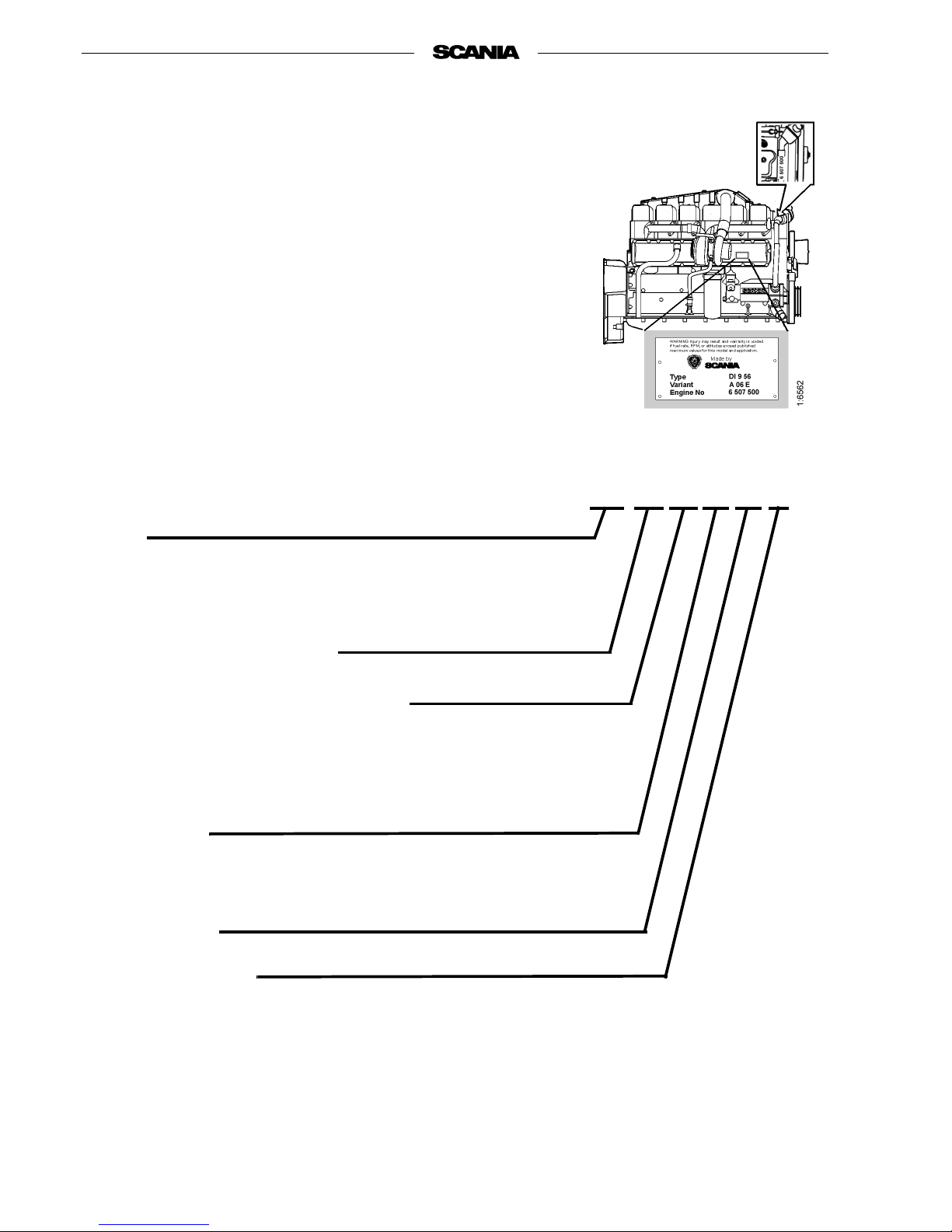
TYPE DESIGNATIONS
The engine type designation indicates, in the form of a code, the type of
engine, its size and applications, etc.
The type designation and engine serial number are indicated on a type plate
affixed to the right-hand side cover behind the oil cleaner. The engine number
is also stamped in the top of the engine block in front of the first cylinder
head. Refer to the illustration.
Engines which hold certification in respect of smoke and emissions are fitted
with a plate which indicates the documents in accordance with which they are
certified. This plate is located on rocker cover number two viewed from the
front.
DI 9 56 A 06 E
Type
DC Supercharged diesel engine with air-cooled charge air cooler.
DI Supercharged diesel engine with liquid-cooled charge air cooler
Displacement in whole dm
3
Performance and certification code
Indicates, together with the application code, the normal gross engine
output.
The actual output setting of the engine is indicated on the engine card.
Application
A For general industrial use
Variant 01-99
Type of regulator
E Electronically controlled governor (DEC2).
Page 11
2003-10:1 © Scania Industrial & Marine Engines 11
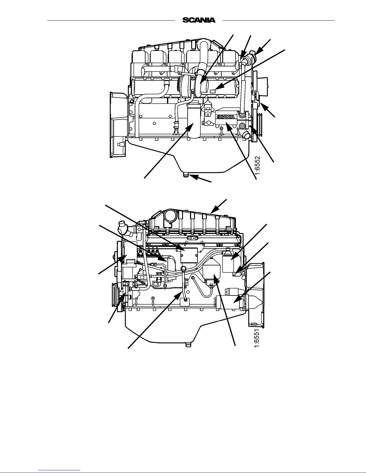
The illustrations show a normal version of a DI9 56 engine.
Your engine may have different equipment from that illustrated.
1. Turbocharger
2. Engine number,
stamped into the engine
block
3. Thermostat housing with
outlet
4. Type plate
5. Automatic belt tensioner
6. Coolant pump
7. Oil cooler
8. Draining, engine oil
9. Oil filter
10. Charge air cooler
11. Fuel filter
12. Draining, coolant
13. Starter motor
14. Oil cleaner
15. Oil dipstick
16. Extra coolant pump
17. Alternator
18. Injection pump with EDC
19. Connector panel DEC2
4
18
6
3
8
9
10
13
7
17
11
2
1
16
12
14
15
5
19
Page 12

12 © Scania Industrial & Marine Engines 2003-10:1
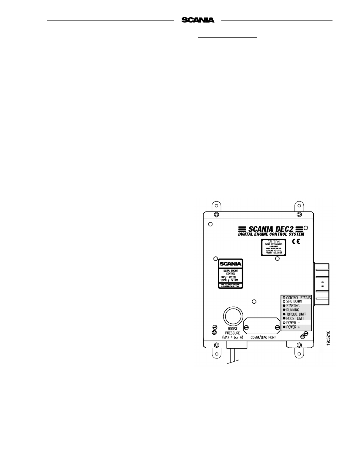
DEC2 CONTROL SYSTEM
This engine has an injection pump with an electromagnetic actuator which
adjusts the control rack to give the correct amount of fuel.
The system which controls the pump is called DEC2 (Digital Engine Control,
generation 2).
The control unit (DEC2) continuously receives signals from sensors for
engine speed, charge air temperature and pressure, coolant temperature, oil
pressure, throttle pedal position and control rod travel in the injection pump.
Using this input data and a control program, the correct amount of fuel for the
current operating conditions can be calculated.
The system's sensors may be used only for DEC2, not for other instruments
or other monitoring purposes.
The control unit contains monitoring functions to protect the engine in the
event of a fault which would otherwise damage it. Faults and the more
important monitoring functions are indicated on the control unit in the form
of light emitting diodes. See illustration on page 15 for a description.
In the event of a fault Power - or Shutdown on the control unit comes on as
well as the main indicator lamp on the main supply box and instrument panel.
If a fault has been indicated on the main indicator lamp, the operator can
determine the cause of the fault with the help of the LEDs on the control unit
and the troubleshooting schedule on page 18, and carry out the required
investigation and remedy.
Depending on the nature of the fault, the control system can take various
steps to protect the engine, reduce its power, allow it to run at a constant low
speed or, if a functional fault is detected, the engine will be switched off
automatically (Shutdown).
In order to read fault indications on the LEDs, there is a lamp test/fault code
switch in the main supply box installed near the control unit.
A PC based program is also available to make it easier for service personnel
to detect and rectify faults which may arise and to adjust certain parameters in
the driving program.
Only authorised personnel are allowed to carry out diagnostic procedures
and program changes.
The locations of the sensors and monitors which send signals to the control
unit will be evident from the figures on pages 13 and 14.
There is a description of the functions of the LEDs during normal operation
on page 15.
There are descriptions of LED indications when a fault has occurred and the
action taken in the case of Power- and Shutdown on page 16.
Troubleshooting and fault code reading are described on pages 17 and 18.
Page 13
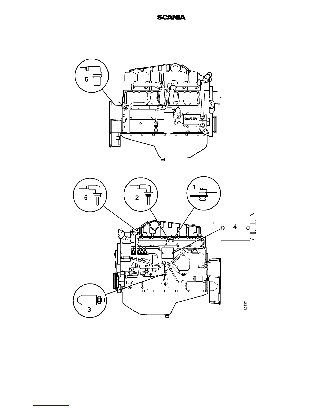
2003-10:1 © Scania Industrial & Marine Engines 13
Location of sensors for DEC2 on DI9Location of sensors for DEC2 on DI9
1. Connection of lead to charge air
pressure sensor
2. Charge air temperature sensor
3. Oil pressure monitor
4. Connector panel
5. Coolant temperature sensor
6. Rotation speed sensors
Page 14
14 © Scania Industrial & Marine Engines 2003-10:1
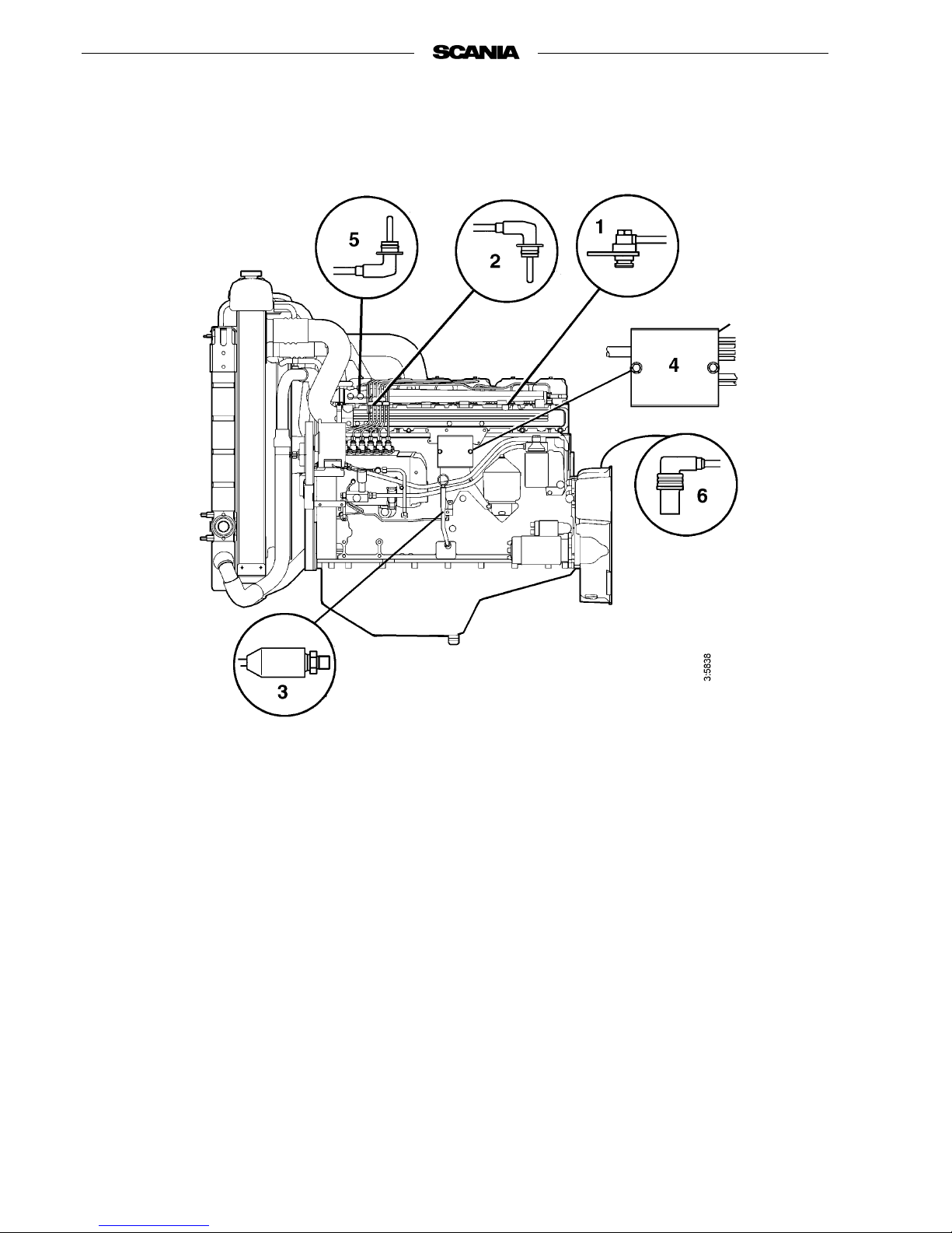
Location of sensors for DEC2 on DC9
1. Connection of lead to charge air
pressure sensor
2. Charge air temperature sensor
3. Oil pressure monitor
4. Connector panel
5. Coolant temperature sensor
6. Rotation speed sensors
Page 15
2003-10:1 © Scania Industrial & Marine Engines 15
LED functions during normal operation
Note: The lamp test/fault code switch should not be
depressed. All LEDs come on briefly when
the control unit is powered up.
CONTROL STATUS
< The LED flashes continuously when the control
unit is supplied with current, regardless of
whether the engine is running or not.
SHUTDOWN
P The LED is out.
STARTING
< The LED lights up as soon as the engine starts to
rotate during an attempt to start it, follows the
programmed starting sequence until it has been
completed and then goes out.
RUNNING
< The LED comes on when the engine has started
and the "Starting"-LED goes out. It remains on
until the engine is stopped.
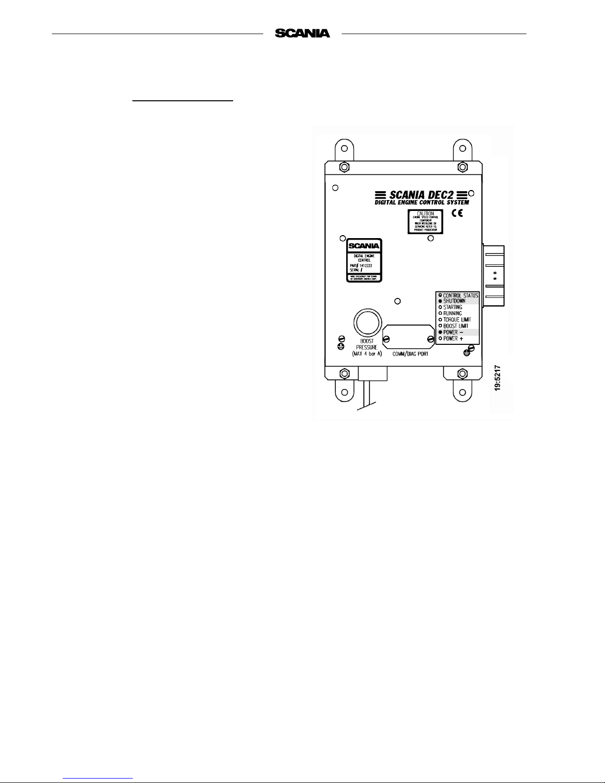
TORQUE LIMIT
< The LED comes on when the control unit senses
that the engine has received the maximum
permissible quantity of injected fuel according
to its power curve. This means 100% power
output at the current rpm. If the load increases,
engine rpm will decrease.
BOOST LIMIT
< The LED comes on when the control unit's
smoke limiter limits the maximum fuel quantity.
Operation of the smoke limiter is dependent on
the charge air pressure.
POWER-
P The LED remains out during normal operation
as long as no fault is detected by the control
unit. See next page for the procedure to be
adopted in the event of a fault.
POWER+
< If the control unit is programmed so that the
engine can be operated with more than one
power/torque curve (map), the following
applies.
The LED comes on when the engine is operated
at more than 100% power output (MAP 2). It
goes out when the engine returns to the 100%
power output curve (MAP 1) or when the power
requirement drops to below 100%.
Page 16
16 © Scania Industrial & Marine Engines 2003-10:1
Action when a fault arises
LED indications in the event of a fault
Note: It is indicated on the main indicator lamp in
the main supply box and on the instrument
panel. The lamp test/fault code switch should
not be depressed.
CONTROL STATUS
< The LED continues to flash even if a fault has
occurred as long as the control unit is powered
up.
POWER-
< If the LED comes on, the control unit has
detected a fault condition which could result in
engine damage if allowed to continue.
The control unit automatically reduces the
power to a special level if this function has
been selected.
Action: If possible reduce engine speed to idle
and conduct troubleshooting according to
instructions on page 17 and the chart on
page 18.
SHUTDOWN
< The LED comes on and the engine is switched
off automatically in the event of a fault so
serious that the engine could be damaged if it is
still in operation.
Action: Conduct troubleshooting according to
instructions on page 17 and the chart on
page 18.
If the engine has not stopped, reduce engine
speed to idle and carry out troubleshooting.
Page 17
2003-10:1 © Scania Industrial & Marine Engines 17
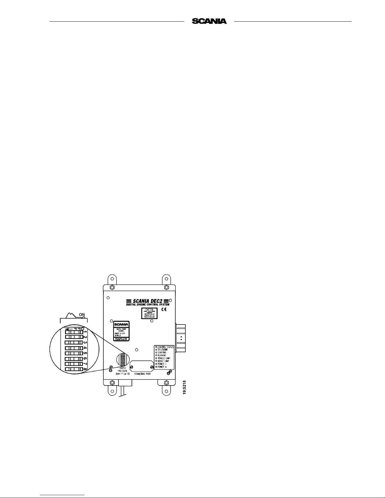
Resetting functions with DIP switches in
control unit
There are 8 DIP switches in the control unit under the
round black rubber cover.
These switches should be in the ON position for
normal operation in accordance with the driving
program. For single speed engines, it may also be
normal for DIP switches 6, 7 and 8 to be in the OFF
position.
Shutdown at threshold values for low oil pressure and
high coolant temperature can be selected by setting
DIP switch 4 to OFF.
With DIP switch 4 in position ON, Power- indication
is obtained for these threshold values. Engine power
output reduction (LOP) can then be selected to prevent
damage to the engine. Changes to the program may be
made by authorised personnel only.
Note: The engine should only be used in an
emergency when the Power- indication
comes on.
Reading fault codes
Note: If the engine has stopped or lost power but
the main indicator lamp is out and neither
POWER- nor SHUTDOWN are on, the fault
is outside the control unit's detection area.
Probable causes: fuel starvation, temporary
overload, mechanical fault.
- Activate the lamp test/fault code switch. In
Scania's electrical equipment the main indicator
lamp is located in this switch in the main supply
box.
- All LEDs will then come on for 2 seconds to
indicate that they are intact and in working order.
This also applies to the main indicator lamp in the
main supply box and on the instrument panel
.
Make a note of any LED that is defective.
- All LEDs will then go out for approximately
4 seconds.
- Following this, a fault code will be indicated on
one of the LEDs for 2 seconds. Note which LED
it is.
- The control unit will then automatically return to
operating mode.
- After having made a note of the fault code, reset
the lamp test/fault code switch and reset the
control unit by turning off its power supply
momentarily.
- The most probable cause of the fault can then be
found in the troubleshooting schedule on the next
page.
- When the fault or faults have been rectified the
engine can be restarted.
- If the control system still gives an indication on
the main indicator lamp, other faults may be
registered. The fault codes must then read again
as above since the system can only show one fault
code at a time.
- The fault or faults will be logged in a special
memory in the control unit where the operating
time concerned is recorded. Stored faults can be
accessed and erased by authorised service
personnel.
Page 18

18 © Scania Industrial & Marine Engines 2003-10:1
READING FAULT CODES
LED INDICATION WHEN THE LAMP TEST/FAULT CODE SWITCH IS ACTIVATED
CONTROL STATUS
SHUTDOWN
STARTING
RUNNING
TORQUE LIMIT
BOOST LIMIT
POWER -
POWER +
Probable cause Action
<
DEC2 has detected an internal fault in the control unit.
Send in the control unit for repair as soon as
possible.
<
The engine temperature has reached the threshold level
or the temperature sensor is inoperative.
Check the cooling system. Check the
temperature sensor and cable routing.
<
The engine has reached the overrevving limit or the
engine speed sensor is inoperative.
Check the wiring and connector. Renew the
engine speed sensor.
<
Control rack position sensor inoperative. Check connectors and cables to governor.
<
The intake air temperature has reached the threshold
level or the charge air temperature sensor is
inoperative.
Check the intake system. Check the temperature
sensor and cable routing.
<
DEC2 detects no charge air pressure.
The charge air pressure sensor is inoperative.
Check the charge air pressure cable. Send in the
control unit if the connection is damaged.
<
Engine speed potentiometer or the idling safety switch
is inoperative.
Check the cable routing, connectors and cables.
<
The oil pressure has dropped to the threshold level or
the oil pressure monitor is inoperative.
Check oil level, connector and cable. Renew the
oil pressure monitor.
<= LED is on
Page 19

2003-10:1 © Scania Industrial & Marine Engines 19
STARTING AND RUNNING
AT FIRST START
When the engine is started for the first time, the maintenance points listed
under "First start" in the maintenance schedule should be followed, see
page 27.
Since the points are important for satisfactory operation of the engine right
from the outset, they are also listed below.
1. Checking the oil level (see page 29).
6. Checking the coolant level (see page 33).
The coolant should contain anti-corrosive to protect the cooling system
from corrosion.
If there is a danger of freezing:
- Only anti-freeze glycol should be used in the coolant as protection
against corrosion. We recommend only nitrite-free anti-freeze glycol
with the following supplier designations:
BASF G48 or BASF D542
- The concentration of glycol should be 30 - 60% by volume depending
on the ambient temperature. 30% glycol by volume provides anti-freeze
protection down to -16°C. See page 33.
- Never top up with only water or only glycol. Fluid losses must always
be replaced with pre-mixed coolant having the same glycol
concentration as that in the engine. If the glycol content drops, both
anti-freeze protection and protection against corrosion are impaired.
Note: A glycol concentration below 30% by volume will not provide
sufficient protection against corrosion. Glycol concentrations
higher than 60% do not improve anti-freeze protection and have
a negative effect on engine cooling capacity.
Coolant composition:
If there is a danger of freezing:
minimum
30% glycol by volume
maximum
60% glycol by volume
If there is no danger of freezing:
7-12% by volume
Scania Corrosion Inhibitor
(no glycol)
The recommended glycols
should not be mixed with
glycol containing nitrite-based
corrosion inhibitor.
Ethylene glycol and
corrosion inhibitor
are toxic if ingested.
Avoid contact with the skin.
Page 20

20 © Scania Industrial & Marine Engines 2003-10:1
If there is no danger of freezing:
-Only Scania Corrosion Inhibitor should be used in the coolant as
protection against corrosion. The correct concentration of anti-corrosive
is 7-12% by volume and this must never drop below 7% by volume. The
inhibitor in Scania Corrosion Inhibitor is free of nitrite.
- First filling: Fill up the system with water + 10% by volume Scania
Corrosion Inhibitor. Use drinking water with a pH of 6 - 9.
- Never top up with only water or only anti-corrosive! Fluid losses must
always be replaced with blended coolant:
water + 10% Scania Corrosion Inhibitor by volume.
Coolant filter (not standard equipment)
Only coolant filter without inhibitor may be used. The use of coolant filters
increases the life of the coolant and reduces the risk of deposition corrosion.
12. Checking the fuel level (see page 40).
15. Checking the electrolyte level in batteries (see page 42).
16. Checking the state of charge in batteries (see page 42).
18. Checking the coolant level monitor (see page 43).
19. Checking the temperature monitor (see page 44).
20. Checking the oil pressure monitor (see page 45).
21. Checking transmission tension (see page 46).
Ethylene glycol and corrosion
inhibitor are
toxic if ingested.
Avoid contact with the skin.
Immobilise the starting device
when working on the engine.
If the engine starts out of
control, there is a
SERIOUS RISK
OF INJURY.
Overdosing with Scania
Corrosion Inhibitor and mixing
with glycol can cause sludge to
be formed.
If a coolant filter has been fitted
it must not contain inhibitor.
Page 21

2003-10:1 © Scania Industrial & Marine Engines 21
CHECKS BEFORE RUNNING
Before running, "Daily maintenance" as described in the maintenance
schedule should be carried out, see page 27.
STARTING THE ENGINE
If the fuel tank has been run dry or if the engine has not been used for a long
time, bleed the fuel system (see page 40).
Out of consideration for our common environment, your new Scania engine
has been designed to use a smaller amount of fuel when starting. Using
unnecessarily large amounts of fuel when starting the engine always results in
the discharge of unburnt fuel.
- Open the fuel cock, if fitted.
- Declutch the engine (not engines with fixed clutch, e.g. generator sets).
- Engines with battery master switch: Switch on the power by means of
the battery master switch.
- DEC2: If the main indicator lamp comes on or flashes when the power is
turned on, this indicates the presence of a fault in the control system or
engine which must be found and rectified before the engine is started.
See page 16.
- Start the engine by means of the starter button or starter key.
Starting at low temperatures
Local environmental requirements must be complied with. Starting aids,
engine heaters and/or flame start devices should be used to avoid starting
problems and white smoke.
To limit white smoke, the engine should be run at low speed and under
moderate load. Avoid running it longer than necessary at idling speed.
Start the engine only in a well
ventilated area.
If it is run in a enclosed space,
there should be an effective
device to draw off exhaust gases
and crankcase gases.
Never use starting spray or
similar to help you start the
engine.
An explosion may occur in the
intake manifold with a risk of
personal injury.
Page 22

22 © Scania Industrial & Marine Engines 2003-10:1
At temperatures below 0°C:
Note: Only use starting aids recommended by Scania.
- The starter motor may only be used for 30 seconds at a time. After that
time it must rest for 2 minutes.
If the engine has flame start:
- Operating flame start without timer relay: Press the control button,
which also acts as a pre-glow button (maximum 20 seconds). The glow
plug continues to glow as long as this button is depressed after the
engine has started. Maximum time is 5 minutes.
- Operating flame start with timer relay: Press the pre-glow button
(maximum 20 seconds). Release it when the engine starts. The timer
relay keeps the glow plug glowing for 5 minutes. If a shorter glow time
is required, press the release button. The key must be set to the
0 position if the start attempt fails.
Note: If the engine is equipped with an INTERLOCK switch, this
switch should be depressed and held down until the oil pressure
has reached a sufficiently high level.
- Generator sets should be operated under load immediately after starting
to avoid the risk of white smoke. This applies in particular to engines
that have been installed without aids for heating or applying a basic
load.
- Warm up the engine with a moderate load. A light load on a cold engine
gives better combustion and faster heating than warming up with no
load.
The starter motor may only be
connected for a maximum of
30 seconds.
There is risk of overheating.
Allow the engine to rest for
2 minutes between each
attempt to start it.
Page 23

2003-10:1 © Scania Industrial & Marine Engines 23
DRIVING
Check instruments and warning lamps at regular intervals.
Rotation speed
The Scania tachometer is divided into sectors of different colours, as follows:
Coolant temperature
Normal coolant temperature when the engine is running should be 70 - 90°C.
DEC2: If the temperature is high, 98°C or higher, it is possible to instruct the
control system to reduce the engine power (Power -) in order to lower the
temperature. See the DEC section on page 17.
If the temperature continues to rise, the engine will be stopped automatically
(Shutdown) at 103°C. See the DEC section on page 17.
Excessively high coolant temperature can damage the engine.
If run for extended periods under an extremely light load, the engine may
have difficulty in maintaining normal operating temperature. However, the
temperature will rise to a normal level again when the load on the engine is
increased.
0 - 500 rpm red area: prohibited engine speed,
passed when stopping and
starting.
500 - 700 rpm yellow area: slow idle.
700 - 2200 rpm green area: normal operating speed.
The engine's operating
speed range is controlled by
the DEC2 control system.
2200 - 2600 rpm yellow/green
striped:
unsuitable operating speed.
May occur when switching
off and during downhill
engine braking
2600 - 3000 rpm red area: prohibited engine speed
WARNING! When driving the vehicle on a steep downhill
slope, or in other installations where the engine can be
driven by the vehicle movement, DEC2 will set zero
fuel supply to protect against overrevving and will
switch off the engine. It must not be disengaged in this
position since this can cause important functions such
as the steering and brake system to fail when the
engine stops rotating.
!
Cooling systems with Scania
radiators and plastic expansion
tanks must not have excess
pressure in the system, i.e.
pressure caps must not be used
on expansion tanks.
Page 24

24 © Scania Industrial & Marine Engines 2003-10:1
Oil pressure
Max. oil pressure:
warm engine running at a speed above 800 rpm 6 bar
Normal oil pressure:
warm engine running at an operating speed of 3 - 6 bar
Min. oil pressure:
warm engine running at a speed of 800 rpm 0.7 bar
At speeds below 800 rpm the gauge may show low oil pressure although no
fault is present.
Oil pressure below 0.7 bar at speeds above 800 rpm will cause engine
damage. The engine must be stopped immediately.
DEC2: The engine is stopped automatically if this function is selected.
See the DEC section on page 17.
Charging indicator lamp
If the lamp comes on during operation:
- Check/adjust the alternator drive belts as described under the
maintenance point. See page 46.
- If the charging indicator lamp is still on, this could be due to an
alternator fault or a fault in the electrical system.
STOPPING THE ENGINE
1. Run the engine without a load for a few minutes if it has been run
continuously with a heavy load.
2. Stop the engine with the stop button. Keep the stop button depressed
until the engine is completely stationary.
3. DEC2: Before switching off, check that the control system's main
indicator lamp is not on or flashing. See page 16 for troubleshooting.
4. Engines with battery master switch: Switch on the power by means of
the battery master switch. (Does not apply to emergency generator sets).
5. Set the control switch to "0". (Does not apply to emergency generator
sets).
High lubricating oil pressure
(above 6 bar) is normal when
starting a cold engine.
High lubricating oil pressure
(above 6 bar) is normal when
starting a cold engine.
There is danger of turbo
damage and post boiling if the
engine is stopped without
cooling.
The power must not be
switched off before the engine
has stopped.
Page 25

2003-10:1 © Scania Industrial & Marine Engines 25
Clutch
- See the manufacturer's instructions for handling and operating the
clutch.
WARNING! If the clutch output shaft is rotating (e.g. in multiple
engine installations where other engines are running), the
clutch can, under its own power, be drawn to the engaged
position.
THIS CAN CAUSE INJURY and engine damage. For this
reason, always secure the clutch in the disengaged position
if there is a risk of the output shaft starting to rotate.
CHECKS AFTER RUNNING
- Check that the power is cut from the battery master switch and that the
control switch is in the "0" position.
- Fill the fuel tank. Make sure that the filler cap and the area round the
filler opening are clean to avoid contamination of the fuel.
- If there is a risk of freezing, the cooling system must be drained if it
does not contain sufficient glycol, see page 33.
- At temperatures below 0°C: Prepare for the next start by connecting the
engine heater.
Topping up with coolant
should be carried out when
the engine is stopped after
the first start.
Immobilise the starting device
when working on the engine.
If the engine starts out of
control, there is a
SERIOUS RISK OF
INJURY
Page 26

26 © Scania Industrial & Marine Engines 2003-10:1
MAINTENANCE
The maintenance programme covers 24 points, divided into the following
main groups:
Lubricating oil system . . . . . . . . . . . . . . . . . page 28
Cooling system . . . . . . . . . . . . . . . . . . . . . . .page 32
Air cleaner . . . . . . . . . . . . . . . . . . . . . . . . . .page 38
Fuel system. . . . . . . . . . . . . . . . . . . . . . . . . .page 40
Electrical system, monitors, batteries, etc. . . page 42
Miscellaneous. . . . . . . . . . . . . . . . . . . . . . . .page 46
The maintenance points are divided into intervals as follows:
Daily maintenance
Maintenance before the first start
Maintenance after the first 400 hours of operation
Periodic maintenance every 200 hours of operation (carried out after 200,
400, 600, 800, etc. hours)
Periodic maintenance every 400 hours of operation (carried out after 400,
800, 1200, 1600, etc. hours)
Periodic maintenance every 1200 hours of operation (carried out after 1200,
2400, 3600, etc. hours)
Periodic maintenance every 2400 hours of operation (carried out after 2400,
4800, etc. hours)
Periodic maintenance every 4800 hours of operation (carried out after 4800,
9600, etc. hours)
Annual Maintenance
Maintenance every 5th year
ENGINES WITH FEW OPERATING
HOURS
Emergency generator sets and the like that are not used regularly should be
run on test and checked in accordance with the generator set manufacturer's
instructions.
Run the engine until it reaches operating temperature and then carry out the
maintenance points below:
1. Checking oil level.
5. Checking coolant level.
8. Checking low pressure indicator.
12. Checking fuel level.
15. Checking electrolyte level in batteries.
16. Checking state of charge in batteries.
17. Cleaning batteries.
22. Look for leakage, rectify as necessary
Immobilise the starting device
when working on the engine.
If the engine starts out of
control, there is a
SERIOUS RISK OF
INJURY
For engines with few operating
hours that do not receive
periodic maintenance according
to the maintenance schedule on
page 27, maintenance should be
carried out in accordance with
the schedule:
"Annually"
"Every 5th year"
Page 27

2003-10:1 © Scania Industrial & Marine Engines 27
MAINTENANCE SCHEDULE
1. More often if required
2. For engines with few operating hours, see page 26.
3. Earlier if low pressure indicator shows red.
4. If inhibitor has not been topped up for five years, the coolant should be changed.
Daily
First
time at
Interval At least
First start
400 h
200 h
400 h
1200 h
2400 h
4800 h
Annually
Every 5th year
LUBRICATING OIL SYSTEM, page 28
1. Checking oil level
2. Oil change
1
3. Cleaning oil cleaner
1
4. Renewing the oil filter
1
COOLING SYSTEM, page 32
5. Checking coolant level
6. Checking coolant
4
7. Cleaning cooling system
1
AIR CLEANER, page 38
8. Test reading low pressure indicator
9. Cleaning the coarse cleaner
1
10. Cleaning or changing filter element
3
11. Changing safety cartridge
FUEL SYSTEM, page 40
12. Checking fuel level
13. Changing main filter
1
14. Checking injectors
ELECTRICAL SYSTEM, page 42
15. Checking electrolyte level in batteries
2
16. Checking state of charge in batteries
2
17. Cleaning batteries
2
18. Checking level monitor
19. Checking temperature monitor
20. Checking oil pressure monitor
MISCELLANEOUS, page 46
21. Checking drive belt
22. Look for leakage, rectify as necessary
23. Checking/adjusting valve clearances
24. Changing (or cleaning) valve for closed crankcase
ventilation
Page 28

28 © Scania Industrial & Marine Engines 2003-10:1
LUBRICATING OIL SYSTEM
OIL GRADE
The engine oil must at least meet the requirements for one of the following
oil classifications:
- ACEA E3, E4 or E5
- The Total Base Number (TBN) should be minimum 12-13
(ASTM 2896).
- Check with your oil supplier that the oil meets these requirements.
- The specified oil change intervals are applicable provided that the fuel
sulphur content does not exceed 0.3% by weight. If the sulphur content
is greater than 0.3% but no more than 1.0%, the oil change interval must
be halved (200 h).
- Viscosities are shown in the figure below.
- When ambient temperatures are extremely low: Consult your nearest
Scania representative to avoid starting difficulties.
Oil analysis
Some oil companies can offer analysis of the engine oil. Such analysis
measures the oil's TBN (Total Base Number), TAN (Total Acid Number),
fuel dilution, water content, viscosity and the quantity of wear particles and
soot in the oil.
The result of a series of analyses is used as the basis for establishing a
suitable oil change interval.
If the conditions are changed, a new oil analysis programme must be carried
out to establish the new change interval.
Additives must not be used.
The oil should be suitable for
all temperature variations until
the next oil change.
-40 -30 -20 -10 0 10 20 30 40
°C
SAE 10W-30
SAE 20W-30
SAE 30
SAE 40
SAE 50
SAE 5W-30
SAE 15W-40
Page 29

2003-10:1 © Scania Industrial & Marine Engines 29
1. Daily:
CHECKING OIL LEVEL
Note: Before checking oil level: Allow the engine to remain stationary
for at least 1 minute.
- The correct level is between the marks on the dipstick. Top up when the
level is at the lower mark.
- Correct type, see "Oil grade" on page 28.
Checking oil level during operation
On some engines the oil level can be checked during operation.
- Remove the oil filler cap to release the pressure in the crankcase.
- Check the level on the dipstick. Correct oil level: 10 mm below the Min.
or Max. mark.
2. Every 400 hours:
OIL CHANGE
Note: If the engine is used for especially demanding operations,
particularly in a dusty environment or if the deposits in the
centrifugal cleaner are thicker than 20 mm: change the oil at
more frequent intervals.
- Unscrew the plug and drain the oil when the engine is hot.
- In certain engines the oil is pumped out by means of a bilge pump.
- Clean the magnet on the plug.
- Refit the plug.
- Fill up with oil.
- Check the level on the dipstick.
Max. 27 dm
3
Min. 20 dm
3
Max. 20 dm
3
Min. 16 dm
3
1 dm3 = 1 litre
Maximum angles of inclination during operation
Maximum permissible angles during operation vary, depending on the type of
oil sump, see illustration.
Note: Specified angle may only occur intermittently.
WA R NI N G
The oil may be hot.
Wear protective gloves and
goggles
Max.
Min.
Use a container to avoid
spillage when changing the oil.
Dispose of used oil through an
authorised waste disposal
contractor.
Page 30

30 © Scania Industrial & Marine Engines 2003-10:1
3. Every 400 hours:
CLEANING THE OIL CLEANER
(at same time as an oil change)
- Unscrew the nut and remove the cover.
- Lift out the rotor and loosen the nut on the rotor bowl three turns.
- If the nut is jammed:
Clamp the nut, absolutely not the rotor, in a vice and turn the rotor three
turns by hand or with a screwdriver.
- Tap the nut lightly with your hand or a plastic hammer, to detach the
rotor bowl from the bottom plate.
- Unscrew the nut and remove the rotor bowl.
- Prize carefully to detach the strainer from the bottom plate.
- Scrape off the deposits from the inside of the rotor bowl. If there are no
deposits, this indicates that the cleaner is not working properly.
- If the deposits are thicker than 20 mm: clean more often.
Open the cap carefully. The
oil may be hot.
Page 31

2003-10:1 © Scania Industrial & Marine Engines 31
- Wash all parts in diesel oil.
- Fit the O-ring in the rotor bowl. Make sure it is not damaged.
Change if necessary.
- Assemble the rotor.
- Tighten the rotor nut firmly by hand
- Refit the rotor.
- Make sure that it spins easily.
- Check that the O-ring in the bowl is undamaged.
A hardened or damaged O-ring must be changed.
- Screw the bowl down hard by hand
If the nut is tightened with a tool, the rotor shaft, nut or bowl may be
damaged.
Functional inspection
The rotor rotates very fast and should continue to rotate when the engine has
stopped.
- Stop the engine when it is warm.
- Listen for a whirring sound from the rotor or feel whether the cleaner
housing is vibrating.
The rotor normally continues spinning for 30 - 60 seconds after the engine
has stopped.
If it does not: dismantle it and inspect the component parts.
Page 32

32 © Scania Industrial & Marine Engines 2003-10:1
4. Every 400 hours:
CHANGING THE OIL FILTER
(at same time as an oil change)
- Remove the old filter.
- Oil the rubber gasket and fit a new genuine Scania filter.
- Tighten the filter by hand.
Never use tools for this. The filter could sustain damage, obstructing
circulation.
- Start the engine and check for leaks.
Important! If the deposits in the centrifugal cleaner are more than 20 mm
thick, the oil filter has to be replaced more often. The same is
true for cleaning the centrifugal filter and changing the oil.
COOLING SYSTEM
5. Daily:
CHECKING COOLANT LEVEL
- Open the expansion tank filler cap and check the coolant level.
- Correct level: (Scania plastic expansion tank)
- Cold engine: The coolant should be level with the bottom of the filler
neck.
- Hot engine: The coolant should be about 25 mm above the lower
edge of the filler hole.
- Other types of expansion tank according to the instructions of the fitter.
- Top up the coolant as necessary, see point 6.
Note: When filling large amounts of coolant:
Never pour cold coolant into a hot engine.
This could crack the cylinder block and cylinder head.
Always top up with ready mixed
coolant.
Open the cap carefully.
Water and steam may
spray out.
Use a container to avoid spillage
when changing the filter.
Dispose of used filters through
an authorised waste disposal
contractor.
Page 33

2003-10:1 © Scania Industrial & Marine Engines 33
6. Every 2400 hours:
CHECKING THE COOLANT
Coolant should be checked as follows:
a) Check the appearance of the coolant.
b) Coolant with glycol only: check the glycol content.
c) Coolant with Scania Corrosion Inhibitor only:
Check the anti-corrosive content.
The composition of the coolant is described in more detail under
"Starting and running"
a)
Checking the appearance of the coolant
- Fill a container with a little coolant and check that it is clean and clear.
- If the coolant is contaminated or cloudy, consider changing it.
- Water added to the coolant should be clean and free from dirt of any
kind.
- Use drinking water with a pH of 6 - 9.
b)
Checking the glycol content
If there is a danger of freezing, use only glycol as an anti-corrosive in the
coolant.
- Cooling systems with glycol should contain at least 30% glycol by
volume to provide acceptable protection against corrosion.
- 30% glycol by volume provides protection against freezing to -16°C. If
additional protection against freezing is required, see the table on the
next page to help you calculate how much glycol you need.
We recommend only nitrite-free anti-freeze glycol with the following
supplier designations:
BASF G48 or BASF D542
- Always top up the anti-freeze if its glycol content drops below 30% by
volume. A glycol content above 60% by volume will not provide greater
protection against freezing.
- The table shows the temperature at which ice starts to form. The engine
will freeze and break at appreciably lower temperatures, see diagram.
- Ice forming in the coolant often causes malfunctioning without any risk
of damage. The engine should not be subjected to heavy loads when ice
starts to form.
Note: The coolant should be changed when the cooling system is
cleaned: every 4800 hours or at least every 5th year.
Important! If a coolant filter is used in the cooling system it must not
contain an inhibitor.
Coolant composition:
If there is a danger of freezing:
minimum
30% glycol by volume
maximum
60% glycol by volume
If there is no danger of freezing:
7-12% by volume
Scania Corrosion Inhibitor
The coolant should be ready
mixed when it is poured into the
cooling system.
Never top up with only water or
only glycol.
Ethylene glycol is
corrosion inhibitor.
Avoid skin contact
with glycol.
The recommended glycol must
not be mixed with glycol having
nitrite-based anti-corrosive.
Risk for build up of sludge and
reduced cooling capacity.
Page 34

34 © Scania Industrial & Marine Engines 2003-10:1
A
A= Area to be avoided. Only for calculating glycol mix.
Coolant freezing temperature when ice starts to form at different glycol mixes
% glycol by
volume
15 20 25 30 35 40 45 50 60
Cooling
system
capacity,
dm
3
Ice slush starts
to form at °C
-6 -9 -12 -16 -22 -27 -36 -46 -55
Glycol dm
3
(litres)
5 6 8 9 11 12 14 15 18 30
6 8 10 12 14 16 18 20 24 40
8 10 13 15 18 20 23 25 30 50
9 12 15 18 21 24 27 30 36 60
11 14 18 21 25 28 32 35 42 70
12 16 20 24 28 32 36 40 48 80
14 18 23 27 32 36 41 45 54 90
15 20 25 30 35 40 45 50 60 100
17 22 28 33 39 44 50 55 66 110
18 24 30 36 42 48 54 60 72 120
20 26 33 39 46 52 59 65 78 130
21 28 35 42 49 56 63 70 84 140
23 30 38 45 53 60 68 75 90 150
24 32 40 48 56 64 72 80 96 160
26 34 43 51 60 68 77 85 102 170
27 36 45 54 63 72 81 90 108 180
29 38 48 57 67 76 86 95 114 190
30 40 50 60 70 80 90 100 120 200
Curve A: Ice formation starts (ice slush)
Curve B: Temperature at which there is a risk of
damage by freezing
1. Safe area
2. Malfunctions may occur (ice slush)
Characteristics of glycol at low
temperatures:
- Example with 30% glycol by volume
- Ice slush starts to form at -16°C
- There is risk for malfunctions at -30°C
- No risk of damage by freezing with a
minimum content of 30% glycol by volume
Anti-freeze glycol, % by volume
Page 35

2003-10:1 © Scania Industrial & Marine Engines 35
c)
Checking protection against corrosion
There must always be sufficient corrosive inhibitor in the coolant to protect
the cooling system against corrosion.
If there is no danger of freezing, only Scania Corrosion Inhibitor should be
used in the coolant.
The inhibitor in Scania Corrosion Inhibitor is free of nitrite.
The correct proportion of anti-corrosive is 7-12% by volume.
- Topping up with 1.0% Scania Corrosion Inhibitor by volume should be
done after every 2400 hours of operation.
- Never top up with only water or only anti-corrosive!
Fluid losses must always be replaced with blended coolant:
water + 10% Scania Corrosion Inhibitor by volume.
Note: The coolant should be changed when the cooling system is
cleaned:
every 4800 hours or at least every 5th year.
Changing the coolant
1. Remove the filler cap from the expansion tank.
2. The coolant is drained at two points:
- the "lowest point" of the engine block, see illustration.
- the "lowest point" of the cooling system.
3. Close the drain taps.
4. Fill up with coolant through the expansion tank's filler hole.
Mix coolant as described on page 33.
Use a container to avoid spillage
when changing the coolant.
Dispose of used coolant through
an authorised waste disposal
contractor.
If a coolant filter has been fitted
it must not
contain inhibitor.
Mixing with glycol or the use of
too much corrosion inhibitor
can lead to build up of sludge
and reduced cooling capacity.
It is highly dangerous to
consume corrosion inhibitor.
Avoid contact with the skin.
Page 36

36 © Scania Industrial & Marine Engines 2003-10:1
Charge air cooler (DI engine)
1.
Drain the coolant from the engine, see "Changing the coolant".
2. Detach the intake manifold from the turbo.
3. Detach the charge air cooler inlet and outlet connections for the coolant.
4. Remove the upper intake manifold.
Take care not to damage the element's water connections.
5. Remove the bolts holding the element and remove the element.
6. Clean the outside of the element. Use a paraffin-based engine cleaner.
7. Fit a new gasket to the lower part of the intake manifold.
8. Screw the element into the lower part. Tighten the bolts to 26 Nm.
9. Fit new V-ring seals to the inlet and outlet connections of the element
and fit the upper part of the intake manifold. Tighten the bolts to 50 Nm.
10. Refit the inlet and outlet connections with new O-rings.
11. Refit the delivery pipe clamps.
12. Connect the intake manifold from the turbo.
13. Fill up with coolant according to the specification on page 33.
1. Intake
manifold,
upper part
2. V-ring seal
3. Element
4. Gasket
5. Intake
manifold,
lower part
1
2
5
3
4
7. Every 4800 hours:
CLEANING THE COOLING SYSTEM
Note: If necessary, the cooling system should be cleaned more often.
External cleaning
Radiator
- Check that the radiator is not clogged on the air side and that the cooling
fins are not damaged.
- Carefully scrape the deposit off the radiator's cooling fins. If necessary,
a paraffin-based engine cleaner can be used.
- Bent fins can be straightened using a wire brush, for example, and
exercising care.
The cooling system must never
be cleaned with caustic soda.
There is a risk of damage to
aluminium parts.
Page 37

2003-10:1 © Scania Industrial & Marine Engines 37
Internal cleaning
Removing oil and grease
- If possible, run the engine until it has reached operating temperature and
then drain the cooling system.
- Remove the thermostats.
- Fill the system with clean, hot water mixed with liquid dishwasher
detergent designed for household use.
Concentration 1% (0.1/10 l).
- Run the engine until warm for about 20-30 minutes. Do not forget the
cab heating system (if fitted).
- Drain the cooling system.
- Fill the system again using clean, hot water and run the engine for about
20-30 minutes.
- Drain the water from the system.
- Refit the thermostats.
- Top up the system with new coolant according to the specification on
page 33.
Removing deposits
- If possible, run the engine until it has reached operating temperature and
then drain the cooling system.
- Remove the thermostats.
- Fill the system with clean, hot water mixed with one of the
commercially available radiator cleaners based on sulphamic acid and
containing dispersing agents. Follow the manufacturer's instructions for
mixing proportions and cleaning times.
- Run the engine for the specified time and then drain the cooling system.
- Refill the system with hot water and run the engine for about 20-30
minutes.
- Drain the water from the system.
- Refit the thermostats.
- Top up the system with new coolant according to the specification on
page 33.
Handling cleaning agents for
the cooling system:
Read the warning label on the
container.
Use a collecting vessel in order
to avoid spillages when
changing the coolant.
Dispose of used coolant through
an authorised waste disposal
contractor.
Page 38

38 © Scania Industrial & Marine Engines 2003-10:1
AIR CLEANER
8. Daily:
READING THE VACUUM INDICATOR
If the red indicator telltale is entirely visible, change or clean the air cleaner
filter element, point 10. This is particularly important if the engine is run at
high loads and high speed.
9. Every 200 hours:
CLEANING THE AIR CLEANER
COARSE CLEANER
1. Remove the cover from coarse cleaner 2.
2. Remove the conical coarse separator. Empty out the particles of dirt and
clean it.
3. Fit the coarse cleaner as shown in the figure and screw the cover in
place.
43
21
1. Filter element
2. Coarse cleaner
3. Cover
4. Vacuum indicator
Air cleaner with coarse cleaner
The coarse cleaner must always
be fitted in an upright position.
10. Every 1200 hours:
CLEANING OR CHANGING THE
FILTER ELEMENT
Note: Earlier if the vacuum indicator shows red
Dismantling
1. Remove the side cover from the air cleaner.
2. Change or clean the element.
Note: Cleaning the element always entails a risk of damaging it. The
element can only be cleaned a maximum of four times. After
cleaning, it has poorer dust capacity than a new element.
3. Mark the filter when it has been cleaned.
Cleaning the element
- Carefully blow the filter element clean using dry compressed air from
the inside.
Note: This filter element must not be washed with water.
1
2
3
1.
Cover
2. Filter element
3. Filter housing
Only use Scania genuine air
filter.
Change the filter element if it is
damaged.
Danger of engine damage if the
filter element is damaged.
Never start the engine without
the air filter.
There is a risk of injury or
serious engine damage.
Page 39

2003-10:1 © Scania Industrial & Marine Engines 39
Checking
- Insert a torch into the element and check from the outside that there are
no holes or cracks in the filter paper.
- Change the filter element if it has the slightest damage. Danger of
engine damage.
Assembly
1. Assemble the air cleaner in reverse order.
2. Reset the red plunger in the vacuum indicator by depressing the button.
11. Every 2400 hours:
CHANGING THE SAFETY CARTRIDGE
Note: Not all filters are equipped with a safety cartridge. When
changing the safety cartridge, take great care to ensure that no
dirt or other impurities can get into the engine.
1. Remove the side cover from the air cleaner.
2. Remove the filter element.
3. Remove the safety cartridge.
4. Fit a new genuine Scania safety cartridge.
5. Change or clean the filter element, see point 10.
6. Assemble the air cleaner.
1. Safety cartridge
Air cleaner with safety cartridge
1
Do not remove the safety
cartridge unnecessarily.
Never clean the
safety cartridge
Page 40

40 © Scania Industrial & Marine Engines 2003-10:1
FUEL SYSTEM
12. Daily:
CHECKING THE FUEL LEVEL
- Top up with fuel if necessary.
- If the tank has been run dry, bleed the fuel system, see point 13.
13. Every 1200 hours:
CHANGING THE FUEL FILTER
Fuel tanks
- Drain any water from the fuel tanks.
Filter
The filter consists of a filter unit.
- Wash the outside of the filter and unscrew it. Discard the filter according
to environmental requirements.
- Fit the new filter and tighten it by hand.
Never use tools for this. The filters can be damaged, obstructing
circulation.
- Bleed the fuel system as described below.
- Start the engine and check for leaks.
Bleeding the fuel system
- Open the bleed screw 1 on the main filter.
- Pump with the hand pump 2 until the fuel flowing out by the bleed
screw is free from air.
- Close the bleed screw. Pump a few more strokes with the hand pump.
If there are starting difficulties after bleeding . . . . .
- Unscrew the injection pump overflow valve 3 half a turn and make
another attempt at starting.
If the engine will still not start . . . . . . .
- Pump with the hand pump until the fuel coming through the overflow
valve is free from bubbles.
- Tighten the overflow valve when the engine has started.
3
Use a container to avoid spillage
when bleeding and changing
components.
Only use Scania genuine fuel
filter.
1
2
Observe the utmost cleanliness
when working on the fuel
system.
There is a risk of engine
malfunction and damage to the
injection equipment.
Page 41

2003-10:1 © Scania Industrial & Marine Engines 41
14. Every 2400 hours:
CHECKING THE INJECTORS
Injectors should be inspected by trained personnel with access to the
necessary equipment. Inspection should be carried out at least once a year or
every 2400 hours.
Removal
1. Clean round the injectors and connections, including clamps and
brackets.
2. Detach the delivery pipe bundle and leak-off fuel lines.
3. Unscrew the injector.
4. Fit protective plugs on the injector and delivery pipe.
5. Lift up the sealing washer from the bottom of the injector seat if it does
not come out together with the injector.
6. Fit a core plug in the injector seat in the cylinder head.
7. Clean the injectors and check/adjust a nozzle tester.
Correct opening pressure, see Technical data, page 54.
Fitting
1. Check that there is no old sealing washer in place and fit a new sealing
washer in the bottom of the injector seat.
2. Fit a new O-ring in the threaded socket nut and a new sealing ring under
the socket nut.
3. Fit the injector.
4. Tighten the socket nut to 70 Nm (7.0 kpm).
5. Fit the delivery pipe and tighten the cap nuts to 20 Nm (2.0 kpm). Fit
clamps and brackets.
Take care to fit the delivery pipe without tension and make sure that
the cone on it is correctly positioned in the connection.
6. Fit the leak-off fuel line. Tighten the bolts to 11 Nm (1.1 kpm).
1. Threaded
socket nut
2. O-ring
3. O-ring
4. Stop ring
5. Guide pin
6. Sealing washer
1. Delivery pipe
2. Cap nut
3. Washer
4. Cone
5. Connection on injector or
injection pump
The delivery pipes must not be
bent.
All clamps must be refitted.
Also wear protective goggles
when testing injectors.
A jet from the injector can
penetrate tissue and cause
serious injury.
Page 42

42 © Scania Industrial & Marine Engines 2003-10:1
ELECTRICAL SYSTEM
15. Every 200 hours:
CHECKING THE ELECTROLYTE
LEVEL IN BATTERIES
1. Unscrew the plugs and check the electrolyte level in all cells.
2. Top up with distilled water until the level is 10-15 mm above the plates.
16. Every 200 hours:
CHECKING THE STATE OF CHARGE IN
BATTERIES
Note: Every 200 hours applies to generator sets and the like. Other
installations every 1200 hours.
- Check the density with an acid tester.
In a fully-charged battery it should be:
1.280 at +20°C
1.294 at 0°
1.308 at -20°C
- If the density is below 1.20, the battery must be charged. A discharged
battery freezes at -5°C.
Do not rapid-charge the battery. This will damage the battery in the
long run.
17. Every 200 hours:
CLEANING BATTERIES
Note: Every 200 hours applies to generator sets and the like. Other
installations every 1200 hours.
1. Clean batteries, cables and cable terminals.
2. Check that all cable terminals are firmly tightened.
3. Grease battery terminal posts and cable terminals with vaseline.
Wear gloves and protective
goggles when charging and
handling batteries
The batteries contain a highly
corrosive acid.
Do not connect the terminals up
incorrectly.
This can cause serious damage
to the electrical system.
If the terminals are shorted,
sparking will occur.
Avoid naked flames or sparks
near the batteries.
When the batteries are
charged, oxyhydrogen gas is
formed which is inflammable
and explosive.
Page 43

2003-10:1 © Scania Industrial & Marine Engines 43
18. Every 1200 hours:
CHECKING THE COOLANT MONITOR
(optional equipment)
1. Start the engine.
2. Lower the coolant level in the expansion tank.
3. Automatic stop in case of fault: Engine stops, indicator lamp is on, and
buzzer sounds if there is no fault in the level monitor.
4. No automatic stop in case of fault: Indicator lamp is on, buzzer sounds
if there is no fault in the level monitor.
5. Top up coolant to the correct level, see page 32.
2-pin level monitor installed in the
expansion tank for radiators
supplied by Scania
Use a container to avoid spillage
when draining the coolant.
Dispose of used coolant through
an authorised waste disposal
contractor.
Page 44

44 © Scania Industrial & Marine Engines 2003-10:1
19. Every 1200 hours:
CHECKING THE TEMPERATURE
MONITOR
1. Drain the coolant, allowing the temperature monitor to be removed.
2. Remove the temperature monitor cable(s).
3. Unscrew the monitor.
4. Refit the cable(s) on the monitor.
5. Submerge the monitor sensor body in water. Heat the water slowly
(about 1° per minute) using an immersion heater, for example.
6. Set the control switch to "ON". Use a thermometer to check that the
warning lamp comes on or that an alarm is initiated at the correct
temperature.
The correct temperature is stamped on the hexagonal part of the
monitor.
The monitor tolerance is ± 3°.
CHECKING THE TEMPERATURE
SENSOR
1. Drain the coolant, allowing the temperature sensor to be removed.
2. Remove the temperature sensor cable(s).
3. Unscrew the sensor.
4. Connect an ohmmeter to the temperature sensor.
5. Submerge the sensor body in water. Heat the water slowly
(about 1° per minute) using an immersion heater, for example.
6. Check the resistance at the temperatures given below.
7. The sensor should give the following readings:
At
temp.
°C
Resistance ΩTolerance
°C
60 134 ± 13,5
±4
90 51,2 ± 4,3
±3
100 38,5 ± 3
±3
2-pin temperature sensor
C = Common connection
1 = Connection C -1 closes at the
stamped temperature
2 = Connection C -2 switches off
at the stamped temperature
2-pin temperature monitor
Use a container to avoid spillage
when draining the coolant.
Dispose of used coolant through
an authorised waste disposal
contractor.
Page 45

2003-10:1 © Scania Industrial & Marine Engines 45
20. Every 1200 hours:
CHECKING THE OIL PRESSURE
SENSOR/MONITOR
Sensor function
Measure the output voltage from the sensor (pin 3) at different oil pressures.
The sensor should give the following readings:
0.85-1.15 bar = 2.45 volts
1.80-2.20 bar = 3.70 volts
2.75-3.25 bar = 4.50 volts
3.79-4.20 bar = 5.20 volts
4.55-5.45 bar = 5.70 volts
5.40-6.6 bar = 6.10 volts
The tolerance values apply at +30°C - 110°C. The tolerance range increases
at lower temperatures, e.g. 0°C = x 1.4.
Monitor function
Connect a test lamp to oil pressure monitor pin 4 (- earth) and check that the
monitor closes at the correct pressure when the engine is started and stopped.
The monitor should close at 0.7 ± 0.15 bar when the engine is stopped.
Important The sensor/monitor must be supplied with voltage when
measuring. Max. load 4 W from test lamp.
CHECKING THE OIL PRESSURE
MONITOR FOR DEC 2
Connect an ohmmeter or test lamp to the oil pressure monitor and check that
the monitor opens/closes at the correct pressure when the engine is started
and stopped. The monitor should open at 1.1 ± 0.15 bar when the engine is
started and close at 0.7 ± 0.15 bar when the engine is stopped.
4
1
3
2
Page 46

46 © Scania Industrial & Marine Engines 2003-10:1
CHANGING THE BATTERY
Removal
1. Disconnect the negative cable (-) from the battery (cable connected to
earth).
2. Disconnect the positive cable (+) from the battery (cable connected to
starter motor).
Fitting
1.
Connect the positive cable (+) to the battery (cable connected to starter
motor).
2. Connect the negative cable (-) to the battery (cable connected to earth).
MISCELLANEOUS
21. Every 1200 hours:
CHECKING THE DRIVE BELT
If the drive belt (1), which is a poly-V belt, is worn or damaged it must be
changed.
Also check that the automatic belt tensioner (2) is in proper working order
and keeps the drive belt correctly tensioned.
The extra coolant pump is driven with a V-belt (3) via a pulley on the
crankshaft. This V-belt should be tensioned with the aid of the pump
attachment until it can be pressed down a maximum of 10 mm with a pressure
of 35-50 N.
Do not connect the terminals
up incorrectly.
This can cause serious damage
to the electrical system.
If the terminals are shorted,
sparking will occur.
Dispose of used batteries
through an authorised waste
disposal contractor.
Page 47

2003-10:1 © Scania Industrial & Marine Engines 47
22. Daily:
CHECKING FOR LEAKAGE,
NECESSARY ACTION
- Start the engine.
- Check for oil, coolant, fuel, air and exhaust leakages.
- Tighten or change leaking connections. Check the overflow holes (1) in
the block which show whether the O-rings between the cylinder liners
and crankcase are leaking, see figure.
a) If coolant is running out, the O-ring is leaking.
b) If oil is running out, the liner shelf is leaking.
A small amount of leakage from the overflow holes during the engine
running-in period is normal. (Seals and O-rings are lubricated with soap
or oil when fitted).
This leakage normally stops after a time.
1
Take care to ensure that any
leaks do not cause pollution.
If serious leakage occurs,
contact your nearest Scania
workshop.
Page 48

48 © Scania Industrial & Marine Engines 2003-10:1
23. Every 2400 hours:
CHECKING/ADJUSTING
VALVE CLEARANCES
Note: Checking/adjusting valve clearances should also be done after the
first 400 hours of operation.
Valve clearances should be adjusted when the engine is cold, at least 30
minutes after running.
The rocker cover gaskets should be changed as necessary. Tightening torque:
26 Nm.
Intake valve clearance: 0.45 mm.
Exhaust valve clearance: 0.80 mm.
Alternative 1
- Set No. 1 cylinder to TDC by turning the engine in its direction of
rotation until all four valves are closed.
- Adjust the following valves. Correct valve clearances are also given on
the instruction plate on one of the rocker covers:
- Set No. 6 cylinder to TDC by turning the engine one revolution in its
direction of rotation and adjust the following valves:
Cylinder 1 Intake and outlet
2 Intake
3 Outlet
4 Intake
5 Outlet
Cylinder 2 Outlet
3 Intake
4 Outlet
5 Intake
6 Intake and outlet
TDC
no. 6 cylinder
TDC
no. 1 cylinder
Intake valve
Exhaust valve
5
4
3
2
1
6
Cylinder numbering
FLYWHEEL
FLYWHEEL
WARNING
Immobilise the starting device
when working on the engine.
If the engine starts out of
control, there is a
SERIOUS RISK
OF INJURY.
Page 49

2003-10:1 © Scania Industrial & Marine Engines 49
Alternative 2
- Set No. 1 cylinder to TDC by turning the engine in its direction of
rotation until all four valves are closed.
- Adjust all valves for No. 1 cylinder. Correct valve clearances are
indicated on the instruction plate on one of the rocker covers.
- Repeat this procedure with the other cylinders in the order
5 - 3 - 6 - 2 - 4 (firing order) by turning the engine 1/3 revolution in its
direction of rotation between each adjustment.
Note:
Readings can be taken from the
flywheel through covers in the
flywheel housing either from
above or underneath depending
on access when fitting.
It says up or down on the flywheel
Both covers are fitted with a cover
at delivery.
Covers for reading
on the flywheel housing
Page 50

50 © Scania Industrial & Marine Engines 2003-10:1
24. Every 2400 hours:
CHANGING (or CLEANING) THE
CLOSED CRANKCASE VENTILATION
VA LV E
Alternative 1:
Change the valve at the specified interval.
Alternative 2:
- Remove the valve after the specified interval.
- Clean the valve by placing it in a bath of diesel fuel oil overnight.
Then rinse it several times in diesel and allow it to drip dry.
- Refit the valve.
- The valve may be reused (cleaned), but not more than twice after the
first 2400 hours of use. Take care to mark the valve after cleaning it.
Page 51

2003-10:1 © Scania Industrial & Marine Engines 51
LONG-TERM STORAGE
If the engine is not to be used for a lengthy period of time, special measures
should be taken to protect the cooling system, fuel system and combustion
chamber from corrosion and the exterior from rusting.
The engine can normally stand idle for up to six months. If it remains unused
for longer than this the following measures, which provide protection for
about four years, should be adopted. An alternative to preparing the engine
for long-term storage is to start the engine and warm it up every 6 months.
Preparing the engine for long-term storage means:
- Thoroughly cleaning the engine
- Running the engine for a certain time using special preservative fuel, oil
and coolant.
- Otherwise preparing the engine for storage (filter changes, lubrication,
etc.).
Preservative coolant
If the engine is to be stored with a full cooling system, use coolant containing
50% glycol by volume. Glycol without nitrite-based inhibitor should be used.
For example BASF G48 or BASF D542.
Preservative fuel
- Use diesel fuel oil mixed with Lubrizol 560A or equivalent.
-Mix 1 cm
3
(ml) Lubrizol 560A in 10 dm3 (l) of fuel.
HANDLING LUBRIZOL 560A
Hazardous!
Contains aromatic hydrocarbons
Use spot extractors where there is a danger of vapour build-up.
Wear protective gloves and goggles when handling Lubrizol. Do not use contaminated clothing.
If it gets in your eyes: Rinse with a gentle stream of water (at least 15 minutes). Seek medical attention.
If it gets on your skin: Wash the affected area with soap and water
If inhaled: Fresh air, rest and warmth
Inflammable: Fire class 2A. Flashpoint + 27.
In case of fire: Extinguish with carbon dioxide, powder or foam.
Storage: In well-sealed receptacle in a dry, cool place. Keep out of reach of children.
!
Ethylene glycol is
toxic if ingested.
Avoid contact with the skin.
Page 52

52 © Scania Industrial & Marine Engines 2003-10:1
Preservative oil
Suitable preservative oil can be supplied by most petroleum companies.
E.g. Dinitrol 40 or the equivalent.
Preparations for storage
- Drain and flush the cooling system. Top up with preservative coolant.
- Warm up the engine on regular fuel. Stop the engine and drain the oil.
- Change the fuel filter and turbo filter.
- Fill the engine with preservative oil up to the minimum level on the
dipstick.
- Mix preservative fuel in a can. Detach the fuel pipe at the feed pump
suction line and connect a hose from the can.
- Detach the fuel pipe at the overflow valve and connect a return hose to
the can.
- Start the engine and run it at about 1000 rpm (not single-speed engines)
for 20-25 minutes.
- Stop the engine, remove the hoses and connect the regular fuel lines.
- Oil the valve mechanism generously with preservative oil.
- Remove the injectors and spray preservative oil into each cylinder,
max 30 cm
3
(ml).
Turn the engine over a few times using the starter motor. Spray a small
amount of oil additionally into each cylinder.
After this the engine must not be cranked. Refit the injectors.
- Drain the preservative oil from the engine. Fresh engine oil can be filled
directly or when the engine is taken out of storage.
- Drain the coolant if the engine is not to be stored with a full cooling
system. Plug and tape over all coolant connections (if the cooling system
is not completely assembled).
- Air cleaner: Clean or change the filter element.
- Cover air intakes and exhaust pipes.
- Alternator and starter motor:
- Spray with water-repellent anti-corrosive oil, CRC 226, LPS1 or the
equivalent.
- Spray the outside of bright engine parts, first with penetrating
preservative oil such as Dinitrol 25B and then with Dinitrol 112 or the
equivalent.
Use a container to avoid spillage
when draining the oil and
coolant.
Dispose of used oil and coolant
through an authorised waste
disposal contractor.
Page 53

2003-10:1 © Scania Industrial & Marine Engines 53
- Attach a label to the engine showing the date of preservation and
clearly stating that it must not be started or cranked.
Batteries
Remove the batteries for trickle charging at the battery charging station.
(Does not apply to batteries which according to the manufacturer do not
require any maintenance). The same is applicable for short-term storage if the
engine has not been prepared for storage as above.
Storage
After the preparations, the engine should be stored in a dry and warm place
(room temperature).
Taking out of storage
(Procedure when the engine is to be put into operation)
- Remove plugs and tape from coolant connections, air intakes and
exhaust pipes.
- Fill the system with coolant, see page 19.
- Check the oil level in the engine or fill up with fresh motor oil.
- Turn the engine over a few times with the injectors removed, at the same
time copiously oiling the valve mechanism with pushrods and tappets.
Important!The engine must be turned over with the injectors removed so
that surplus preservative oil will be pressed out of the
cylinders.
- Fit the injectors.
- Empty the fuel system's main filter of preservative oil.
- Bleed the fuel system, see page 40.
- Wash off any externally applied preservative oil, using white spirit.
STORED ENGINE
Date . . . . . . . . . . .
Do not start or crank!
Wear gloves and protective
goggles when charging and
handling batteries
The batteries contain a highly
corrosive acid.
Page 54

54 © Scania Industrial & Marine Engines 2003-10:1
TECHNICAL DATA
GENERAL DC9 DI9
Number of cylinders
6 in line
Cylinder diameter mm
115
Stroke mm
144
Capacity dm
3
(litres)
9,0
No. of main bearings
7
Firing order
1 - 5 - 3 - 6 - 2 - 4
Compression ratio
17:1
Engine direction of rotation viewed from rear
Anti-clockwise
Fan direction of rotation viewed from front
Clockwise
Cooling
Liquid
Valve clearances, cold engine
intake valve mm
exhaust valve mm
0,45
0,80
Weight, without coolant or oil kg
*With charge air cooler, radiator,
expansion tank and pipes
890* 840
Power
see engine card, "Engine record card"
LUBRICATION SYSTEM
Max. oil pressure
(hot engine at engine speeds
above 800 rpm bar (kp/cm
2
)
6
Normal oil pressure
(hot engine at operating speeds) bar (kp/cm
2
)
3 - 6
Min. oil pressure
(hot engine 800 rpm) bar (kp/cm
2
)
0,7
Oil capacity, see page 29
Crankcase pressure with
closed crankcase ventilation mm VP
-55 - +20
Page 55

2003-10:1 © Scania Industrial & Marine Engines 55
FUEL SYSTEM DC9 DI9
Pump setting BTDC
See plate on rocker cover
Injector, opening pressure bar (kp/cm
2
)
300
Low idle speed rpm
700
Maximum full load speed
See engine card
Fuel
Diesel fuel oil
1
Tightening torques:
Threaded socket nut for injectors Nm
Cap nut for delivery pipe Nm
Oil leakage connection Nm
70
20
11
1
see page 56
COOLING SYSTEM
Number of thermostats 1
Thermostat, opening temperature
°C79
Coolant temperature:
system at atmospheric pressure
°C
system at overpressure
°C
70 - 93
70 - approx. 100
Volume, incl 0.75 m
2
radiator and
expansion tank dm
3
(litres)
50 53
ELECTRICAL SYSTEM
System voltage V
24
Alternator, current A
65 or 90
Starter motor output kW (hp)
4,0 (5,4)
Monitors, alarm values:
oil pressure monitor bar (kp/cm
2
)
temperature monitor °C
0,7
± 0,15
Stamped on hexagonal part of monitor
Page 56

56 © Scania Industrial & Marine Engines 2003-10:1
FUEL
Diesel fuel oil
The composition of the diesel fuel oil has a great influence on the functioning
and the service life of the engine and the injection pump. The engine output
and exhaust emissions are also dependent on the fuel quality. The
requirements and testing standards for the most important properties are
described in the service manual in sections which can be ordered from Scania
dealers or directly from Scania. The address of Scania is printed on the cover.
The diesel fuel must meet European standard EN 590.
The table below shows the requirements for some of the most important
properties:
Environmentally favourable fuels (low sulphur fuels)
There are three classes of so called environmentally favourable fuels
(SS155435).
Class 1 is sulphur-free and class 2 is low in sulphur. Compared with class 3
(normal fuel), these fuels are less dense and this reduces engine power output.
Only class 1 fuel should be used with a catalytic converter.
Short term use of fuel with a higher sulphur content than 0.05% by weight
will not cause permanent damage to the catalytic converter.
The catalytic converter may, however, require fuel with low sulphur content
for some time after this to regain its normal efficiency.
Property Requirement
Viscosity at 40°C 2.0 - 4.5 mm2/s (cSt)
Density at 15
°C 0.82 - 0.86 kg/dm
3
Sulphur (concentration by mass) max. 0.3%
Ignitability (CET rating) min. 49
Flashpoint 56°C
Page 57

2003-10:1 © Scania Industrial & Marine Engines 57
Temperature dependence of diesel fuel
At temperatures lower than those specified for the diesel fuel, paraffin wax
may precipitate from the fuel and block filters and pipes. The engine can then
lose power or stop.
The diesel fuel is adapted for use in the specific climate of each country. If a
vehicle or an engine is to be operated in a temperature zone with lower
temperature than normal, first identify the temperature properties of the
fuel concerned.
The properties of the fuel when cold can be improved by adopting one of the
following measures before the temperature drops:
- If the fuel concerned cannot cope with the expected temperatures, and
diesel fuel is not available with the correct temperature properties, we
recommend that an electric fuel heater is installed as a preventative
measure.
- The low temperature properties of diesel fuel may be improved by
adding kerosene as a preventative measure. A maximum of 20% may
be added. When refuelling, the kerosene should be added first, so that it
mixes thoroughly with the diesel fuel.
Note: It is prohibited to use kerosene in engine fuel in
some countries.
- To prevent water in the fuel from freezing and forming ice, a maximum
of 0.5-2% alcohol (isopropanol) may be added.
Drain fuel tanks and drain or change fuel filters regularly.
It is not permitted to mix
kerosene with diesel fuel that is
already adapted for the climate
concerned. The injection pump
may be damaged. All use of
paraffin other than kerosene is
forbidden, as it causes engine
damage.
It is not permissible to mix
petrol with diesel fuel. In the
long term, petrol may cause
wear to the injection pump and
at worst it may also cause
damage to the engine.
Page 58

58 © Scania Industrial & Marine Engines 2003-10:1
ALPHABETICAL INDEX
Air cleaner . . . . . . . . . . . . . . . . . . . . . . . . . . . 38
Air cleaner, prefilter . . . . . . . . . . . . . . . . . . . . 38
Air cleaner, safety cartridge . . . . . . . . . . . . . . 39
Air cleaner, vacuum indicator . . . . . . . . . . . . 38
Air filter, element . . . . . . . . . . . . . . . . . . . . . . 38
Batteries . . . . . . . . . . . . . . . . . . . . . . . . . . . . . 42
Bleeding, fuel system . . . . . . . . . . . . . . . . . . . 40
Certified engines . . . . . . . . . . . . . . . . . . . . . . . . 5
Changing the battery . . . . . . . . . . . . . . . . . . . 46
Changing the fuel filter . . . . . . . . . . . . . . . . . . 40
Checks after running . . . . . . . . . . . . . . . . . . . 25
Checks before running . . . . . . . . . . . . . . . . . . 21
Clutch . . . . . . . . . . . . . . . . . . . . . . . . . . . . . . . 25
Coolant . . . . . . . . . . . . . . . . . . . . . . . . . . . . . . 33
Coolant level . . . . . . . . . . . . . . . . . . . . . . . . . . 32
Coolant level monitor . . . . . . . . . . . . . . . . . . . 43
Coolant temperature . . . . . . . . . . . . . . . . . . . . 23
Coolant temperature monitor . . . . . . . . . . . . . 44
Coolant temperature sensor . . . . . . . . . . . . . . 44
Coolant, changing . . . . . . . . . . . . . . . . . . . . . . 35
Cooling system . . . . . . . . . . . . . . . . . . . . . . . . 32
Cooling system, cleaning . . . . . . . . . . . . . . . . 36
Corrosion inhibitor . . . . . . . . . . . . . . . . . . . . . 35
DEC2 Control system . . . . . . . . . . . . . . . . . . . 12
DEC2 fault codes . . . . . . . . . . . . . . . . . . . . . . 17
DEC2 sensor . . . . . . . . . . . . . . . . . . . . . . . . . . 13
Drive belt . . . . . . . . . . . . . . . . . . . . . . . . . . . . 46
Driving . . . . . . . . . . . . . . . . . . . . . . . . . . . . . . 23
Electrical system . . . . . . . . . . . . . . . . . . . . . . . 42
Engine speed . . . . . . . . . . . . . . . . . . . . . . . . . . 23
Environmental responsibility . . . . . . . . . . . . . . 4
Filter, air cleaner . . . . . . . . . . . . . . . . . . . . . . . 38
Filter, fuel . . . . . . . . . . . . . . . . . . . . . . . . . . . . 40
First start . . . . . . . . . . . . . . . . . . . . . . . . . . . . . 19
Fuel level . . . . . . . . . . . . . . . . . . . . . . . . . . . . 40
Fuel specifications . . . . . . . . . . . . . . . . . . . . . 56
Fuel system . . . . . . . . . . . . . . . . . . . . . . . . . . . 40
Fuel system, bleeding . . . . . . . . . . . . . . . . . . . 40
Glycol . . . . . . . . . . . . . . . . . . . . . . . . . . . . . . . 33
Injectors . . . . . . . . . . . . . . . . . . . . . . . . . . . . . 41
Leakage . . . . . . . . . . . . . . . . . . . . . . . . . . . . . . 47
LED functions . . . . . . . . . . . . . . . . . . . . . . . . . 15
Lubricating oil system . . . . . . . . . . . . . . . . . . 28
Lubrication oil pressure sensor/monitor . . . . . 45
Lubrication pressure . . . . . . . . . . . . . . . . . . . . 24
Maintenance . . . . . . . . . . . . . . . . . . . . . . . . . . 26
Maintenance Schedule . . . . . . . . . . . . . . . . . . 27
Oil analysis . . . . . . . . . . . . . . . . . . . . . . . . . . . 28
Oil capacity . . . . . . . . . . . . . . . . . . . . . . . . . . . 29
Oil change . . . . . . . . . . . . . . . . . . . . . . . . . . . . 29
Oil cleaner . . . . . . . . . . . . . . . . . . . . . . . . . . . . 30
Oil filter . . . . . . . . . . . . . . . . . . . . . . . . . . . . . 32
Oil grade . . . . . . . . . . . . . . . . . . . . . . . . . . . . . 28
Oil level . . . . . . . . . . . . . . . . . . . . . . . . . . . . . 29
Oil pressure . . . . . . . . . . . . . . . . . . . . . . . . . . . 24
Oil pressure monitor, DEC2 . . . . . . . . . . . . . . 45
Preface . . . . . . . . . . . . . . . . . . . . . . . . . . . . . . . 2
Prefilter, air cleaner . . . . . . . . . . . . . . . . . . . . 38
Preparations for storage . . . . . . . . . . . . . . . . . 51
Safety cartridge, air cleaner . . . . . . . . . . . . . . 39
Safety information . . . . . . . . . . . . . . . . . . . . . . 6
Safety precautions for care and maintenance . . 8
Safety precautions for handling materials . . . . 8
Safety precautions for running the engine . . . . 7
Starting the engine . . . . . . . . . . . . . . . . . . . . . 21
Stopping the engine . . . . . . . . . . . . . . . . . . . . 24
Storage . . . . . . . . . . . . . . . . . . . . . . . . . . . . . . 53
Taking out of storage . . . . . . . . . . . . . . . . . . . 53
Technical data . . . . . . . . . . . . . . . . . . . . . . . . . 54
Temperature monitor . . . . . . . . . . . . . . . . . . . 44
Troubleshooting DEC2 . . . . . . . . . . . . . . . . . . 16
Type designations . . . . . . . . . . . . . . . . . . . . . . 10
Vacuum indicator . . . . . . . . . . . . . . . . . . . . . . 38
Valve clearances . . . . . . . . . . . . . . . . . . . . . . . 48
Warranty . . . . . . . . . . . . . . . . . . . . . . . . . . . . . . 1
 Loading...