


Product information PI 44
Documents for interface-planning for tool turrets
Serie 0.5.440.xxx 0.5.433.xxx 0.5.435.xxx 0.5.436.xxx
2010-07-15

®
Contents
|
|
|
|
|
|
Overview: control circuit diagrams |
.................................................................................................4 |
|
|
Appendix: |
|
|
|
Wiring layouts.............................................................................................................. . |
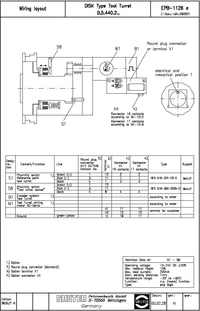
EPB – 1126 |
|
|
|
EPB – 1130 |
|
|
|
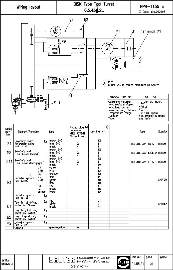
EPB – 1155 |
|
|
Hydraulic diagrams............................................................................................................... |
HP-489 |
|
|
|
HP-490 |
|
|
|
HP-498 |
|
|
Diagram of function ............................................................................................................ |
SK - 1471 |
|
|
|
SK - 1473 |
|
|
|
SK - 1500 |
|
|
|
SK - 1515 |
NOTE:
The information contained in this Projcet Planning Guide is in conformity with the knowledge at
the point of printing. Subject to modifications which occur within the framework of continuous further development.
The quality of our products can only be guaranteed, if the instructions of this project planning guide are complied with!
PI_44_e_08-11-26.fm
PI 44 e |
3 |

®
Overview: control circuit diagrams
Overview: control circuit diagrams
Turret series |
Wiring layout |
Hydraulic diagram |
Diagram of function |
0.5.440.2xx |
EPB – 1126 |
HP-489 |
SK-1473 |
|
|
|
|
0.5.433.2xx |
EPB – 1155 |
HP-489 |
SK-1515 |
|
|
|
|
0.5.435.2xx |
EPB – 1130 |
HP-490 |
SK-1471 |
|
|
|
|
0.5.436.2xx |
EPB – 1155 |
HP-498 |
SK-1500 |
|
|
|
|
NOTES
On turrer motor with absolute sensor:
–Reference position switch not required
–Move to reference position cancelled
On turrer motor with incremental tranducer:
–Reference position switch required
–Move to reference position must be made
4 |
PI 44 e |

 Loading...