


 Loading...
BA 892 e
2007-03-27
O p e r a t i n g I n s t r u c t i o n s
for
Disk-type tool turret
0.5.473.520 -
107 468
110660
111092
111432
112862
115702
125365
F:\Sauter\FRAME-AR\TD\0-5-473-\eng\Ba892\DB_Rev_BA-892.fm
Product data as per nameplate on the housing
1.Classification number (series, size)
2.Identification number
3.Order number
4.Gear ratio
x.x.xxx.x xx |
|
xxx xxx |
|
xx-xxx-xx-xx |
|
xxx |
|
Basis-BA: 06-10-23 |
Manual translation |
The present manual is part of the product.
The manual should be kept in an easily accessible place during the product’s lifetime.
The manual should be passed on to the next owner/user of the product.
Make sure that any possible supplement received is duly added to the manual.

F:\Sauter\FRAME-AR\TD\0-5-473-\eng\Ba892\BA_473520_ölIVZ.fm
Table of contents
Interpretation of symbols . . . . . . . . . . . . . . . . . . . . . . . . . . . . . . . . 5
1 Safety notes . . . . . . . . . . . . . . . . . . . . . . . . . . . . . . . . . . . . . . . . . . . 7
1.1 Use within specifications . . . . . . . . . . . . . . . . . . . . . . . . . . . . . . . . . . 7 1.2 Required skills . . . . . . . . . . . . . . . . . . . . . . . . . . . . . . . . . . . . . . . . . . 7 1.3 Notes on product-specific risks . . . . . . . . . . . . . . . . . . . . . . . . . . . . . 7 1.4 Disposal. . . . . . . . . . . . . . . . . . . . . . . . . . . . . . . . . . . . . . . . . . . . . . . 8 1.5 Liability and warranty. . . . . . . . . . . . . . . . . . . . . . . . . . . . . . . . . . . . . 9
2 Product description. . . . . . . . . . . . . . . . . . . . . . . . . . . . . . . . . . . . 10
2.1 Designation of parts . . . . . . . . . . . . . . . . . . . . . . . . . . . . . . . . . . . . 10 2.2 Technical data . . . . . . . . . . . . . . . . . . . . . . . . . . . . . . . . . . . . . . . . . 12
3 Manual mode . . . . . . . . . . . . . . . . . . . . . . . . . . . . . . . . . . . . . . . . . 14
4 Maintenance . . . . . . . . . . . . . . . . . . . . . . . . . . . . . . . . . . . . . . . . . . 17
4.1 Safety notes . . . . . . . . . . . . . . . . . . . . . . . . . . . . . . . . . . . . . . . . . . 17 4.2 Service intervals . . . . . . . . . . . . . . . . . . . . . . . . . . . . . . . . . . . . . . . 18 4.3 Maintenance work . . . . . . . . . . . . . . . . . . . . . . . . . . . . . . . . . . . . . . 19 4.4 Repairs after fault conditions. . . . . . . . . . . . . . . . . . . . . . . . . . . . . . 22 4.5 Aligning the tool disk . . . . . . . . . . . . . . . . . . . . . . . . . . . . . . . . . . . . 25 4.6 Replacing the cooling lubricant valve . . . . . . . . . . . . . . . . . . . . . . . 26 4.7 Adjusting the angular encoder. . . . . . . . . . . . . . . . . . . . . . . . . . . . . 27 4.8 Replacing the angular encoder . . . . . . . . . . . . . . . . . . . . . . . . . . . . 29 4.9 Proximity switch S7 . . . . . . . . . . . . . . . . . . . . . . . . . . . . . . . . . . . . . 33 4.10 Solenoid . . . . . . . . . . . . . . . . . . . . . . . . . . . . . . . . . . . . . . . . . . . . . 36
5 Replacement parts. . . . . . . . . . . . . . . . . . . . . . . . . . . . . . . . . . . . . 38
Replacement parts for turrets (without tool drive)
Replacement parts tool drive for turret
Survey: Disk-type tool turret 0.5.480.5..
3

Table of contents
Appendix
Diagram of functions: Disk-type tool turret . . . . . . . . . . . . . . . . . . . . . . . . . SK - 919 Diagram of functions: Disk-type tool turret . . . . . . . . . . . . . . . . . . . . . . . . . SK - 920 Wiring diagram: Disk-type tool turret . . . . . . . . . . . . . . . . . . . . . . . . . . . . . . EP - 870 Diagram of functions: Tool drive . . . . . . . . . . . . . . . . . . . . . . . . . . . . . . . . . SK - 940 Wiring diagram: Tool drive . . . . . . . . . . . . . . . . . . . . . . . . . . . . . . . . . . . . . . EP - 855
Contact/Order information
4
F:\Sauter\FRAME-AR\TD\0-5-473-\eng\Ba892\BA_473520_ölIVZ.fm
F:\Sauter\FRAME-AR\TD\0-5-473-\eng\Ba892\Konventionen_BA.fm
Interpretation of symbols
Interpretation of symbols
Warning notes
WARNING 1)
This warning designates a potentially hazardous situation which may lead to serious injuries, or even death.
WARNING 1)
Risk of electric shock due to high voltages!
CAUTION 1)
This caution designates a potentially hazardous situation in which the product or property in its environment could be damaged.
IMPORTANT
For application notes and other useful information.
Clearing
Clear machine before carrying out any further work!
1)Classification of signal words acc. to ANSI Z535.4
5
Interpretation of symbols
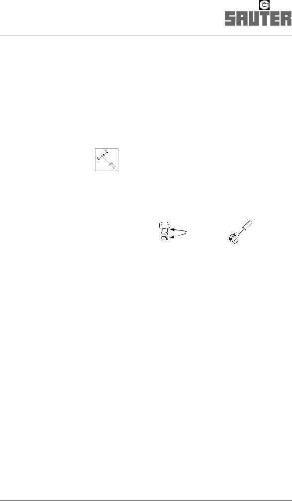
Symbols for action instructions
Designates an action instruction
Designates the result of an action
Designates a cross-reference
Tools required: here, hexagonal pin wrench complete with
T grip
Use M10 bolts, quality 12.9; use MoS2 to lubricate the points marked, tightening torque 70 Nm.
M10 - 12.9 |
MoS2 |
70 Nm |
|
|
|
Abbreviations
max. |
maximum |
perm. |
permissible |
Fig. |
figure |
if nec. |
if necessary |
approx. |
approximately |
acc. |
according (to) |
incl. |
inclusive (of) |
F:\Sauter\FRAME-AR\TD\0-5-473-\eng\Ba892\Konventionen_BA.fm
6

F:\Sauter\FRAME-AR\TD\0-5-473-\eng\Ba892\Sicherheit_allgem_480-473.fm
Safety notes
1 Safety notes
The turret corresponds to the state of the art and the recognized technical safety rules. Nevertheless hazards and risks can occur.
1.1Use within specifications
Install and operate turret only in machines complying with the relevant regulations for workspace protection.
Operate turret only in perfect condition and in compliance with the Operating Instructions.
1.2Required skills
•Work may only be performed on the turret by qualified staff.
These are persons who are able to identify risks and to prevent possible hazards on the basis of their special training and their experience (IEC 60 201-1).
•All work on the electrical system is to be carried out by a qualified electrical engineer only.
•Only trained and competent personnel may work on the turret; this personnel must have been instructed in accordance with the Operating Instructions and directly on the turret.
1.3Notes on product-specific risks
Setting tasks require a 24V DC power supply.
Clearing required prior to any work:
Switch the machine off.
Push the motor protection switch for the turret into the OFF position.
7

Safety notes
WARNING
In the event of a fault or a collision, unexpected rotation of the tool disk is possible.
Injury hazard.
CAUTION
Do not attempt any further switching operations, if the turret is damaged, as otherwise considerable consequential damage may be caused.
Call SAUTER Service.
CAUTION
Functional faults may be caused by an ingress of chips and contamination.
Close open tool locations and cooling lubricant bores by means of suitable closing plugs.
|
For manual operation, turn the motor shaft with the help of a |
|
hexagonal pin wrench, complete with T-grip. |
|
WARNING |
|
A reversal of the moment of the motor results in the |
|
acceleration of the motor shaft. The hexagonal pin wrench may |
|
thus be unexpectedly accelerated. |
|
Therefore, in order to avoid the ejection of the hexagonal pin |
|
wrench and resulting injuries, firmly grip the hexagonal pin |
|
wrench. |
|
_480-473.fm |
|
_allgem |
1.4 |
-AR\TD\0-F:\Sauter\FRAME5-473-\eng\Ba892\Sicherheit |
Disposal |
Comply with all national and regional disposal regulations and laws.
8

Liability and warranty
1.5Liability and warranty
The information contained in these Operating Instructions is in conformity with the knowledge at the point of printing.
Subject to modifications which occur within the framework of continuous further development.
All liability and warranty shall be excluded if
•the notes and instructions contained in these Operating Instructions are not complied with,
•the product is not used as directed,
Use within specifications, page 7
•the product including accessories is incorrectly operated,
•the product including accessories is incompetently repaired and maintained,
•conversions and functional changes are implemented without approval by the manufacturer,
•no suitable spindle units are used as stipulated in SAUTER Product Information PI 14.2, for example,
•no suitable tool disks and tool holders are used,
•no original replacement parts are used.
F:\Sauter\FRAME-AR\TD\0-5-473-\eng\Ba892\Gewährleistung.fm
9

Product description
Designation of parts
2Product description
2.1Designation of parts
3
2
1
4
5
1Locating disk
2Tool drive unit: gear housing
3Tool drive motor 1)
4Covering hood for electric components
5Turret housing
1) not included in scope of delivery
F:\Sauter\FRAME-AR\TD\0-5-473-\eng\Ba892\PB_473520-25.fm
10

Product description Designation of parts
F:\Sauter\FRAME-AR\TD\0-5-473-\eng\Ba892\PB_473520-25.fm
6
7
8
9
13
10
12
11
15
14
16
17
6Solenoid
7Terminal box: tool drive motor
8Flange plate: tool drive motor
9Turret motor
10Electric connection: turret
11Angular encoder
12Proximity switch S7 “Check pre-indexation”
13Cooling lubricant cartridge
14Proximity switch S11 “Tool drive disengaged”
15Proximity switch S10 “Tool drive engaged”
16Solenoid
17Tool drive coupling
11

Product description
Technical data 0.5.473.520
2.2Technical data
Number of indexing positions |
|
|
8 or 12 or 16 |
|
|
|
|
|
|
Perm. tangential torque 1) |
|
Nm |
3,000 |
|
(turret locked) |
|
|
|
|
at calculated safety |
|
|
1.3 |
|
|
|
|
|
|
Perm. mass moment of inertia of tool disk, |
kgm2 |
1.8 – 7.5 2) |
|
|
tool holders, and tools |
|
|
|
|
|
|
|
|
|
Perm. unbalance (load moment) caused |
|
Nm |
63 |
|
by tool holders and tools |
|
|
|
|
|
|
|
|
|
Indexing times 2) |
|
|
|
|
|
|
|
41 + α |
0,.1 |
Theoretical cycle time |
|
s |
i × ---------------- × 0,.17 + |
|
|
n |
|
||
(unlock/turn/lock) |
|
|
|
|
at rotating angle α [degrees] |
|
|
|
|
Gear ratio |
i |
|
see turret type plate |
|
Motor speed |
n |
rpm |
see motor rating plate |
|
|
|
|
|
|
Perm. indexing frequency |
|
min-1 |
10 – 5.5 2) |
|
|
|
|
|
|
Operating voltage/mains frequency |
|
|
see motor rating plate |
|
|
|
|
|
|
Degree of protection |
|
|
IP 65 |
|
|
|
|
|
|
Turret mass |
|
kg |
approx. 70 |
|
(without tool disk) |
|
|
|
|
|
|
|
|
|
Perm. ambient temperature range |
|
°C |
+10 ... + 40 |
|
|
|
°F |
+50 ... + 104 |
|
|
|
|
|
|
Operating pressure for cooling lubricant 3) |
|
|
|
|
Cooling lubricant valve – standard version |
bar |
7 |
|
|
constant supply |
|
|
||
externally switched supply |
|
bar |
14 |
|
Medium pressure valve (option) |
|
bar |
25 |
|
|
|
|
|
|
1)The perm. loads refer to processing without load shocks. Whenever processing is subject to intermittent cuts, shocks or impacts, a significantly reduction in the values needs to be taken into account.
2)Depending on gear ratio and mains frequency
3)In order to achieve an extended service life of the cooling lubricant valve, it is advisable to filter the cooling lubricant by ≤ 100 m. Post-connected loads (spindle units with
internal cooling lubricant guide a.o.) may require a higher degree of filter fineness. Note and comply with the manufacturer’s instructions!
F:\Sauter\FRAME-AR\TD\0-5-473-\eng\Ba892\Td_473520.fm
12

Product description
Technical data 0.5.473.520
Tool drive 1)
Mass (without any motor) |
|
kg |
|
approx. 40 |
|||
|
|
|
|
|
|
|
|
Gear ratio |
i |
|
41/41 |
41/31 |
|
41/27 |
41/21 |
|
|
|
|
|
|
|
|
Perm. speed 2) on tool drive coupling |
nperm |
rpm |
4000 |
|
|||
Max. perm. torque 2) 3) |
M |
Nm |
|
|
32 |
|
|
on tool drive coupling |
perm |
|
|
|
|
|
|
|
|
|
|
|
|
|
|
|
|
|
|
|
|
|
|
Transferable power 2) |
P |
kW |
|
|
10 |
|
|
|
perm |
|
|
|
|
|
|
|
|
|
|
|
|
|
|
Suitable for spindle units |
|
|
|
|
|
|
|
coupling profile |
|
|
17 × 14 |
|
DIN 5482 |
||
|
|
|
|
|
|
|
|
1)The data stated here may differ on special versions.
2)Mperm is the permissible peak load for the gears.
 The torque must be limited on the motor frequency converter to the value indicated, while adhering to the gear ratio involved!
The useful power data depend on the performance characteristic curve of the motor type used.
3)The permissible torque can be utilized for non-pulse machining operations.
For strongly pulsed machining operations - e.g. inserted tooth milling cutters and others - only a significantly reduced drive torque should be applied to protect the gears against any overloads.
F:\Sauter\FRAME-AR\TD\0-5-473-\eng\Ba892\Td_473520.fm
13
Manual mode
3 Manual mode
In manual mode, the mechanical functions of the disk-type tool turret will be checked:
•following initial assembly to the machine
•during troubleshooting
•after a renewed setup following fault conditions
Clearing required prior to any work:
Switch the machine off.
Push the motor protection switch for the turret into the OFF position.
1.Undo fixing screws of covering hood, withdraw covering hood to rear.
If necessary, use push-off screw.
2. Remove screw plug on motor housing.
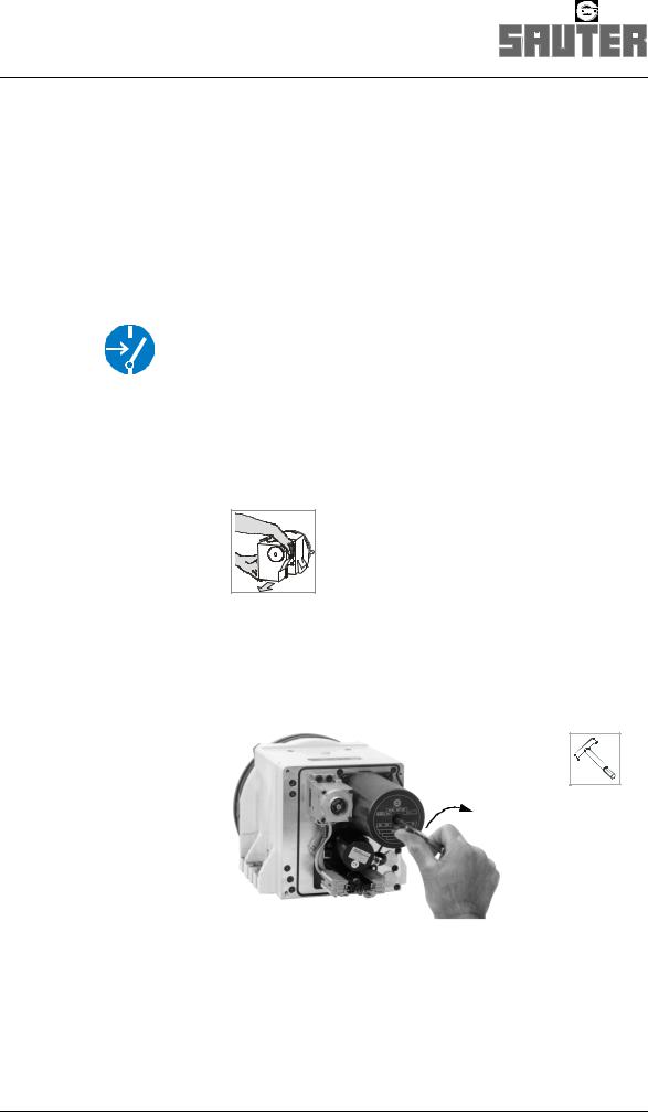
Unlock turret
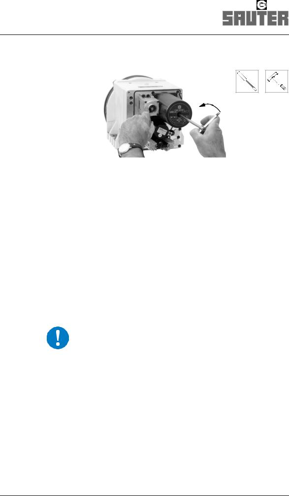
3.Use a hexagonal pin wrench, complete with T-grip, to rotate the motor shaft.
If the disk-type tool turret is locked, the locating disk (or tool disk) does not co-rotate; the centre position of the lock can be felt.
14
F:\Sauter\FRAME-AR\TD\0-5-473-\eng\Ba892\HB_480.fm
Manual mode
WARNING
A reversal of the moment of the motor results in the acceleration of the motor shaft. The hexagonal pin wrench may thus be unexpectedly accelerated.
Therefore, in order to avoid the ejection of the hexagonal pin wrench and resulting injuries, firmly grip the hexagonal pin wrench.
4.Keep the same direction of rotation, continue to rotate.
The disk-type tool turret unlocks; a reversal of the moment on the motor shaft can be felt.
Rotate tool disk
5.Keep direction of rotation, continue to rotate disk until locating disk (or tool disk) starts to turn as well.
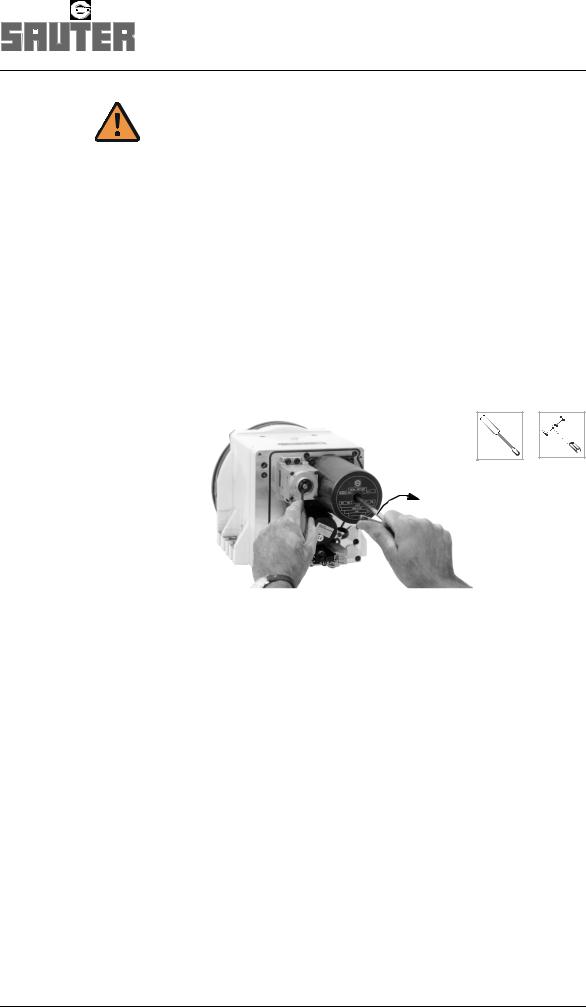
6.Keep direction of rotation, continue to rotate disk until locating disk (or tool disk) has reached the position required, then press in the keeper by means of a screwdriver.
The preindexing bolt engages into a hole.
The tool disk cannot be rotated any further.
F:\Sauter\FRAME-AR\TD\0-5-473-\eng\Ba892\HB_480.fm
15
Manual mode
Lock turret
7.Reverse direction of rotation on the motor shaft whilst simultaneously pressing in keeper.
The disk-type tool turret locks.
The lock resistance can be felt when rotation is continued. The locking process ends, if the centre position of the lock can be felt.
On completion of setup or maintenance work:
8.Screw in plug and fit covering hood.
Note position of cables in order to avoid any pinching of the same.
Lock turret in position 1
IMPORTANT
For some setup and maintenance work the disk-type tool turret has to be locked in position 1.
Precondition
•Numeral 1 of the locating disk has reached its 12 o’clock position relative to the turret base area.
or
•Position 1 of the tool disk is in working position.
1.Use a hexagonal pin wrench, complete with T-grip, and rotate the motor shaft until position 1 has been reached.
2.Press in the keeper by means of a screwdriver and rotate the motor shaft until the disk-type tool turret locks (see above).
16
F:\Sauter\FRAME-AR\TD\0-5-473-\eng\Ba892\HB_480.fm

Maintenance
Safety notes
4 Maintenance
Turret maintenance comprises the following tasks:
•Cleaning,
•Checking,
•Setting and
•Repair.
The service life of the turret is approx. 2–3 million switchings or approx. 5 years.
The service life of the tool drive unit is approx. 8000 operating hours.
These values apply to
•collision-free operation,
•compliance with the specified operating conditions and the permissible loads,
Technical data, page 12
4.1Safety notes
Page 7
F:\Sauter\FRAME-AR\TD\0-5-473-\eng\Ba892\IH_SI_Zeit_480-473.fm
17

Maintenance
Service intervals
4.2Service intervals
Plan your tasks carefully in order to provide for troublefree operation and reduce necessary downtimes to a minimum.
IMPORTANT
Maintenance intervals must be adapted to the operating conditions involved.
if required |
Clean tool drive coupling. |
User |
|
|
|
|
|
|
Check tool drive coupling for damage, |
User |
|
|
replace if necessary. |
|
|
|
|
SAUTER Service |
|
|
|
|
|
after 4000 operating hours |
Check cooling lubricant valve for wear |
User |
|
of the machine |
and leakage. |
Page 26 |
|
respectively |
Replace any defective parts. |
||
|
|||
|
|
|
|
|
Check oil of the turret gearbox |
User |
|
|
chamber; |
Page 19 |
|
|
if necessary, replenish oil. |
||
|
|
|
|
|
Check grease condition of tool drive |
User |
|
|
|
||
|
unit; if necessary, replenish grease. |
Page 21 |
|
|
|
||
|
|
|
|
after 2½ years |
Check all electrical lines and |
User |
|
respectively |
connections for mechanical damage as |
|
|
|
well as embrittlement. |
Specialist electrical |
|
|
Replace any defective parts. |
engineer 1) |
|
|
|
|
|
after 8000 operating hours |
Change the oil of the turret gearbox |
User |
|
of the machine |
chamber. |
Page 19 |
|
respectively |
|
||
|
|
||
|
|
|
|
|
The service life of the tool drive unit |
SAUTER Service |
|
|
may possibly be reached, depending |
|
|
|
on the operating conditions involved. |
|
|
|
A general overhaul is recommended |
|
|
|
for further trouble-free operation. |
|
|
|
|
|
|
after approx. 2–3 million |
The service life of the turret may |
SAUTER Service |
|
indexing operations |
possibly be reached, depending on the |
|
|
respectively |
operating conditions involved. |
|
|
|
A general overhaul is recommended |
|
|
|
for further trouble-free operation. |
|
|
|
|
|
1)These are persons who are able to identify risks and to prevent possible hazards on the basis of their special training and their experience
(IEC 60 201-1).
F:\Sauter\FRAME-AR\TD\0-5-473-\eng\Ba892\IH_SI_Zeit_480-473.fm
18

F:\Sauter\FRAME-AR\TD\0-5-473-\eng\Ba892\IH_Oel_Rev_480516-20-25.fm
Maintenance work
Turret gearbox chamber
4.3Maintenance work
Turret gearbox chamber
The turret gearbox chamber has to be serviced after 4,000 operating hours.
Clearing required prior to any work:
Switch the machine off.
Push the motor protection switch for the turret into the OFF position.
IMPORTANT
Improperly disposed used oil is a danger for our environment.
Pay attention to the legal regulations for the waste disposal of used oil.
In line with the setup position of the disk-type tool turret, the following apertures (1) for draining or replenishing oil are provided:
1 |
1 |
Checking the oil
Carefully unscrew oil drain plug and drain the oil (max. 10 cm3) into a suitable container.
19

Maintenance work
Turret gearbox chamber
Assess oil condition
Condition |
Cause |
Action |
|
|
|
|
|
|
|
|
|
Oil black or brown, without |
Natural consumption |
– |
|
metallic abrasion |
|||
|
|
||
|
|
|
|
Oil black or brown, with |
Internal parts of turret are |
|
|
metallic abrasion |
damaged |
|
|
|
|
Request SAUTER Service! |
|
Oil white, mixed with cooling |
Turret sealings are damaged |
||
|
|||
lubricant |
|
|
|
|
|
|
|
None oil left |
Turret sealings are damaged |
|
|
|
|
|
Changing the oil
Open oil drain plug, drain waste oil.
Close oil drain plug.
Remove screw plug from oil charging hole.
Fill oil
300 cm3 |
|
|
lubricating oil |
C |
acc. to ISO 6743/6 |
viscosity |
ISO VG 46 |
acc. to DIN 51562 |
|
|
|
Screw in screw plug.
F:\Sauter\FRAME-AR\TD\0-5-473-\eng\Ba892\IH_Oel_Rev_480516-20-25.fm
20
F:\Sauter\FRAME-AR\TD\0-5-473-\eng\Ba892\IH_Fett_WZA_473.fm
Maintenance work
Tool drive
Tool drive
The tool drive is lubricated with grease.
The grease needs to be checked after 4,000 hours of operation of the tool drive.
Clearing required prior to any work:
Switch the machine off.
Push the motor protection switch for the turret into the OFF position.
Preparation
Provide access to the aperture (1) on the tool drive.
1
Checking the grease condition
Unscrew screw plug on aperture (1).
Rotate gear and assess grease condition:
Condition |
|
Cause |
|
Measure |
|
|
|
|
|
|
|
|
|
|
No grease visible on gear |
|
Natural consumption |
|
Replenish grease. |
|
|
|
|
|
Grease: black or brown, |
|
Traces of natural wear |
|
– |
without metallic abrasion |
|
|
||
|
|
|
|
|
|
|
|
|
|
Grease: black or brown, |
|
Internal parts of turret are |
|
|
with metallic abrasion |
|
damaged |
|
|
|
|
|
|
|
Grease: white, mixed with |
|
Turret sealings are damaged |
Request SAUTER Service! |
|
cooling lubricant |
|
|
||
|
|
|
|
|
Grease mixed with oil |
|
Turret sealings are damaged |
|
|
|
|
|
|
|
|
Replenishing the grease |
|
|
|
|
|
|
|
|
|
|
max. 20 cm3 |
ISOFLEX NBU 15 (KLÜBER) |
|
|
|
|
|
|
Close aperture (1) by means of screw plug.
21

Repairs after fault conditions
Possible faults and remedies
4.4Repairs after fault conditions
Clearing required prior to any work:
Switch the machine off.
Push the motor protection switch for the turret into the OFF position.
Fault |
Cause |
Remedy |
Who carries out |
|
|
|
|
|
this task? |
|
|
|
|
|
|
|
|
|
|
|
|
|
|
Turret |
|
|
|
|
|
|
|
|
|
|
|
Incorrect center height, |
Collision when turret is |
Turn back tool disk in |
User |
|
|
tool disk offset relative |
locked |
the annular groove and |
Page 25 |
|
|
to locating disk |
|
align |
|
|
|
|
|
|
|
|
|
Tool disk does not |
Gearwheels are |
SAUTER |
|
|
|
rotate |
defective |
Service |
|
|
|
|
|
|
|
|
|
|
Proximity switch S11 |
Check proximity switch |
User |
|
|
|
does not switch |
S11; if necessary, set |
Page 37 |
|
|
|
|
or replace |
|
|
|
|
|
|
|
|
|
Turret is difficult to |
Insufficient oil in the |
Check oil |
User |
|
|
operate |
gearbox chamber |
|
Page 19 |
|
|
|
|
|
|
||
|
|
|
|
|
|
(Thermo protection |
Contactor is defective |
Check motor drive |
User |
|
|
device has responded) |
|
|
|
|
|
|
|
|
|
|
|
Turret no longer locks |
Collision during |
SAUTER |
|
|
|
or the pre-indexing bolt |
pivoting |
Service |
|
|
|
gets caught |
|
|
|
|
|
|
|
|
|
473.fm- |
|
Tool disk does not stop |
Angular encoder is not |
Check angular |
User |
||
|
|||||
in the selected position |
correctly adjusted or |
encoder, set or replace |
Page 27, |
480 |
|
|
defective |
if necessary |
page 29 |
||
|
Stör_ |
||||
|
|
|
|
||
|
|
|
|
\eng\Ba892\IH_ |
|
|
|
necessary |
|
||
|
Proximity switch S7 |
Check proximity switch |
User |
|
|
|
does not switch |
S7, set or replace if |
Page 33 |
|
|
|
|
|
|
||
|
|
|
|
AR\TD\0-5-473- |
|
|
|
|
|
||
|
|
|
|
F:\Sauter\FRAME- |
22
Loading...