


STK4141V
Ordering number: EN 1649C
±
θ
°
°
°
−
°
±
8
Thick Film Hybrid IC
STK4141 V
AF Power Amplifier (Split Power Supply)
(25W + 25W min, THD = 0.08%)
Features
• The STK4102II series (THD=0.4%), STK4201V series
(THD=0.08%) and STK4141X series (THD=0.02%)
are pin-compatible. Once the PCB pattern is designed,
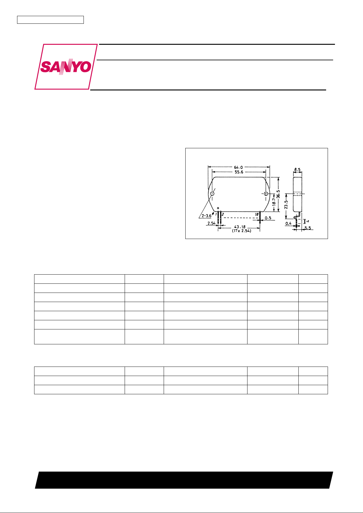
Package Dimensions
unit: mm
4040
[STK4141 V ]
you can easily satisfy the repuirements for new sets simply by changing the IC.
• Built-in muting circuit to cut off various kinds of pop
noise.
• Greatly reduced heat sink due to substrate temperature
125 ° C guaranteed.
• Current mirror circuit application reduces distortion to
0.08%.
Specifications
Maximum Ratings
Parameter Symbol Conditions Ratings Unit
Maximum supply voltage V
Thermal resistance
Junction temperature Tj 150
Operating substrate temperature Tc 125
Storage temperature Tstg
Available time for load short-circuit t
at Ta = 25 ° C
max
CC
j-c 2.6
30 to +125
V
= ± 27V, R
s
CC
f = 50Hz, P
= 8 Ω ,
L
= 25W
O
40.5 V
C/W
C
C
C
2s
Recommended Operating Conditions
Parameter Symbol Conditions Ratings Unit
Recommended supply voltage V
Load resistance R
CC
L
SANYO Electric Co., Ltd. Semiconductor Business Headquarters
TOKYO OFFICE Tokyo Bldg., 1-10, 1 Chome, Ueno, Taito-ku, TOKYO, 110 JAPAN
at Ta = 25 ° C
27.0 V
Ω
61197HA (ID) / D2793HO (KOTO) / 8298MO / N224MY, TS 5-1990 No. 1649—1/5
−
STK4141 V
Operating Characteristics
at Ta = 25 ° C, V
= ± 27.0, R
CC
Parameter Symbol Conditions min typ max Unit
Quiescent current I
CCO
P
O
1
Output power
P
2
O
Total harmonic distortion THD f = 1kHz, P
Frequency response f
Input impedance r
Output noise voltage V
Neutral voltage V
Muting voltage V
, f
L
H
i
NO
N
M
V
= ± 32.5V 20 40 100 mA
CC
f = 20Hz to 20kHz,
THD = 0.08%
V
= ± 24V, f = 1kHz,
CC
THD = 0.2%, R
P
= 1W, dB 20 to 50k Hz
O
f = 1kHz, P
V
= ± 32.5V, Rg = 10k Ω
CC
V
= ± 32.5V
CC
= 4 Ω
L
= 1W 0.08 %
O
+0
−
3
= 1W 55 k Ω
O
Notes. For power supply at the time of test, use a constant-voltage power supply
unless otherwise specified.
For measurement of the available time for load short-circuit and output
noise voltage, use the specified transformer power supply shown below.
The output noise voltage is represented by the peak value on rms scale
(VTVM) of average value indicating type. For AC power supply, use an AC
stabilized power supply (50Hz) to eliminate the effect of flicker noise in AC
primary line.
= 8 Ω (non-inductive), Rg = 600 Ω , VG = 40dB
L
25 W
25 W
1.2 mVrms
70 0 +70 mV
-2 -5 -10 V
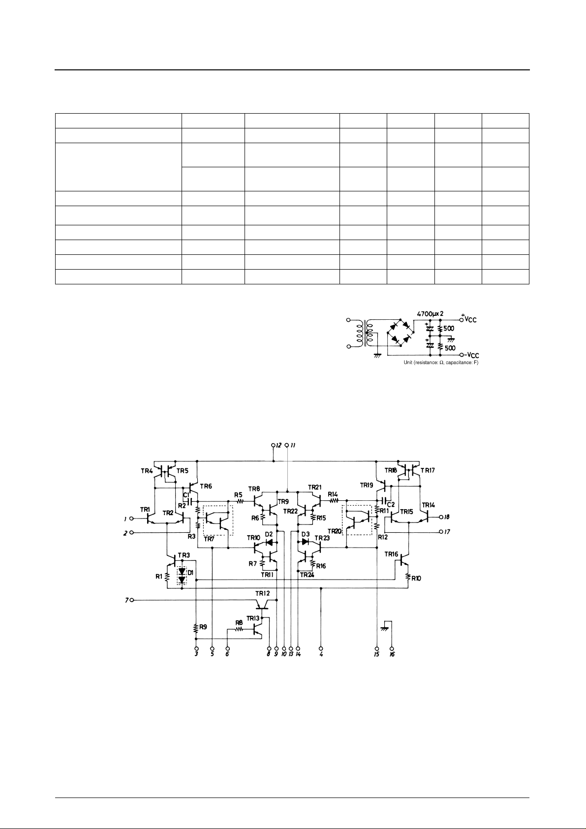
Specified Transformer Power Supply
(Equivalent to RP-25)
Equivalent Circuit
No. 1649—2/5
 Loading...