


Sanyo SGP-EZ240M2G2, SGP-WE80M1, SGP-EZ150M2G2, SPW-GU105XH, SGP-WE170M1 User Manual
...Gas Driven VRF
M Series
GAS DRIVEN VRF
ELECTRIC VRF
COMMERCIAL SPLIT SYSTEMS
ROOM AIR CONDITIONERS
HEATING SOLUTIONS
SANYO Air Conditioners. The natural choice.
SANYO GHP - the natural choice
Gas Heat Pump M Series - the perfect solution when you’re short of power
SANYO has been developing GHP VRF systems since 1980, during which time we have been committed to delivering ground-breaking technology. As a result, the commercial range of GHP VRF systems is leading the industry in the development of efficient and flexible systems, making them the natural choice for commercial projects, especially for those projects where power restrictions apply. As you would expect, all of our gas driven VRF systems have the highest reliability rates in the industry and a leading customer service programme.
The M Series of gas drivenVRF systems offers increased efficiency and performance across the range. Now more powerful than ever before, it can connect to up to 48 indoor units.
Improvements include increased part load performance, reduced gas consumption with a Miller-cycle engine and reduced electrical consumption from using DC fan motors.
•Up to 71kW of cooling from a maximum running capacity of 5
AMPs
•Single phase power supply across the range
•The option of natural gas or LPG as its main power source
•Freehotwater!Awaterheatexchangertoconnecttodomestic hot water systems 13-25 HP (Heat Pump only)
•Option of DX or chilled water for indoor heat exchange
•Option to connect to third party Air Handling Units
•Reduced CO2 emissions
Power supply problems?
If you are short of electrical power, gas heat pump could be the perfect solution.
•Runs on gas and just needs single phase supply.
•Enables the building’s electrical power supply to be used for other critical electrical demands.
• Reduces capital cost to upgrade power substations to run heating and cooling systems.
•Reduces power loadings within a building especially during peak periods.
•Electricity supply freed up for other uses such as IT servers, commercial refrigeration, manufacturing, lighting etc.
SANYO benefits
High-efficiency operation
13-25 HP models are equipped with a high-performance air exchanger and a newly developed refrigerant heat exchanger for high-efficiency operation, making them one of the most energy efficient solutions on the market.
Lowest nitrogen oxide emissions
The GHP VRF systems have the lowest nitrogen oxide emissions, 66% below the standard. In a pioneering development, the SANYO GHP features a brand new lean-burn combustion system that utilises air fuel ratio feedback control to reduce NOx emissions to an all-time low.
Excellent economy
The SANYO GHP provides quick and powerful cooling/ heating and increases delivery of heat into the space by the efficient recovery of heat from the engine cooling water, which is injected into the refrigerant circuit.
In addition, the use of engine waste heat ensures that our gas heat pump air conditioner requires no defrost cycle, therefore providing continuous 100% heating performance in severe weather conditions with an outside air temperature as low as -20°C. During cooling mode the rejected heat from the engine is available for use within a hot water system and can supply up to 25kW of hot water at 75 °C.
High performance
With its advanced heat exchanger design, this new GHP system offers improved efficiency and reduced running costs, which, coupled with improved engine management systems, have greatly improved the system COP rating.
New electrical power generator model
The biggest breakthrough in recent GHP technology is the launch of the ECO G Power, which provides 4.0kW of power. That’s enough electricity to power 8 computers or other applications.
GHP features at a glance
•Power generation of up to 4kW on ECO G Power version
•Up to 25kW hot water generation on all 2 pipe heat pump versions
•Chiller module available for water based solutions
•100% heating performance even at -200c ambient
•180% indoor connectability (Single heat pump module)
•Single phase power required through the range
2 |
Rating Conditions: Cooling Indoor 27°C DB 19°C WB Outdoor 35°C DB 24°C WB Heating Indoor 20°C DB Outdoor 7°C DB 6°C WB |
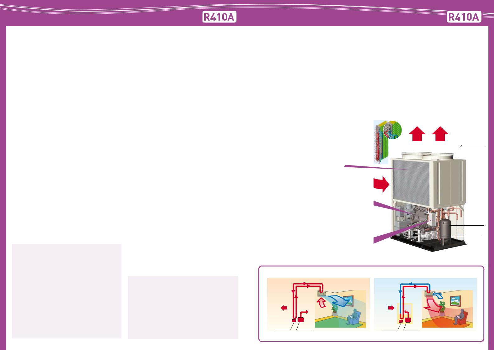
What is a GHP?
The application principle of Variable Refrigerant Flow (VRF) systems for projects with multiple indoor unit is now very much an integral element of the UK air conditioning market place.
A GHP is no different in principle, however, developed by SANYO in 1980 the GHP outdoor unit is fitted with a combustion engine, powered by
Natural gas or LPG, to drive the refrigerant compressor.
Variable capacity is achieved via the engine speed being altered up and down just as an inverter compressor speed is controlled in the electric VRF equivalent. The GHP therefore is an ideal solution where electrical power is at a premium (or no 3 phase available) however it also boasts a number of additional benefits/functions that are not
available on an electric equivalent.
High efficiency heat exchanger |
Exhaust |
The ‘M’ series GHP continues to use a ‘hybrid’ heat exchanger for |
|
improved efficiency. By interlacing the refrigerant coil with the |
|
radiator carrying the coolant from the engine, the condensing |
Fan |
capacity and radiator performance is balanced to an optimum |
|
level. This combination ensures the cooling efficiency drop in |
|
cold ambient is kept to a minimum, heating performance is |
|
down to -20oc and maintain a high COP. |
|
Higher engine efficiency |
Air |
|
By utilising a Miler-Cycle engine, the compression stroke is reduced and therefore pumping losses are minimised. As a result the expansion volume ratio increases and the efficiency improves.
Miller cycle: This heat cycle has the characteristic that the closing time for the suction valve in regard to the base engine is late. As a result, the expansion stroke becomes relatively longer in comparison to the compression stroke.
Refrigerant heat exchanger
By fitting a new plate heat exchanger the engine waste heat is recovered efficiently and reused to improve performance. In addition a proportionate control 3 way change over valve is used for control of the engine cooling water to increase efficiency in heating operation
Accumulator
Compressor
How a GHP works - High performance and low operating costs by using gas fuel
|
|
|
|
|
Cooling |
|
|
|
|
|
|
Heating |
|
|
|
|
Refrigerant gas |
|
|
Refrigerant liquid |
|||||||
|
|
|
|
Refrigerant |
|
|
|
|
Refrigerant |
Cold air |
|||
|
|
|
|
liquid |
|
|
|
|
|
||||
|
|
|
|
|
|
|
|
gas |
|
||||
|
|
|
|
|
|
|
|
|
|
|
|||
Heat |
|
|
|
Outdoor unit |
Heat |
|
|
Outdoor unit |
Warm air |
||||
|
|
|
|
Warm air |
|
|
|
|
|
|
|||
|
|
|
|
|
|
|
|
|
|
||||
|
|
|
|
|
Cold air |
|
|
|
|
|
|
|
|
|
|
|
|
|
|
|
|
Engine waste heat |
|||||
Discharge of heat |
|
|
|
|
Hot water |
Absorption of heat |
|
|
|
||||
absorbed from the |
|
|
|
|
function |
|
|
|
|
|
|
|
|
|
|
|
|
from the outside air |
|
|
|
|
|
|
|
||
inside of the room |
|
|
|
|
|
|
|
|
|
|
|
|
|
|
|
|
|
|
by evaporation of |
|
|
|
|
|
|
|
|
by liquefaction of |
|
|
|
|
|
refrigerant. |
|
|
|
|
|
|
|
refrigerant. |
|
|
|
|
|
|
|
|
|
|
|
|
|
Compressor |
|
|
|
Gas engine |
Compressor |
|
|
|
Gas engine |
|
|||
|
|
|
|
|
Absorption of heat from the room by |
|
|
|
|
|
|
Discharge of heat generated by |
|
|
|
|
|
|
liquefaction of refrigerant. |
|
|
|
|
|
|
condensation of refrigerant. |
|
Rating Conditions: Cooling Indoor 27°C DB 19°C WB Outdoor 35°C DB 24°C WB Heating Indoor 20°C DB Outdoor 7°C DB 6°C WB |
|
|
|
|
|
|
3 |
||||||

ECO G 3 Way Heat Recovery VRF System
Still the only heat recovery (3 way) GHP system in Europe.
The new M Series ECO G 3 Way offers even more performance and outstanding features when you need simultaneous heating and cooling. Now with increased capacities available from 16HP to 25HP, SANYO offers the greatestchoiceandflexibilitytosolveanypowerproblemor site requirement.
•Simultaneous heating and cooling for total control
•Reduced gas consumption by Miller-cycle engine
•Reduced electrical power consumption by using DC motors
•New lightweight design by use of aluminium engine block reduces weight by 110kg
•Part load efficiencies increased
•Connectability increased to up to 36 indoor units
•Now available in 16, 20 and 25HP
•200mmaximumallowablepipinglength(L1)(equivalent-refer to technical manual)
•Diversity ratio 50% - 130%
•Extended pipe runs (total 500m)
•Silent mode offers a further 2dB(A) reduction
•10,000 run hours between engine service intervals (equivalent to one maintenance every 3.2 years*)
•Full heating capacity down to -20°C
•No defrost cycle
* Assuming 3120 running hrs per year - 12 hrs x 5 days x 52 weeks
ECO G 3 Way is ideal for the following types of application:
•Office buildings with a diverse range of room temperatures due to differing load profiles.
•Buildings with computer rooms requiring year round cooling.
Additional parts
By taking its power supply from the nearest indoor unit, the SANYO solenoid valve (change-over box) does not require any additional fused spur and at only 150mm high can be easily installed within a 200mm void space.
LPG option
The option of using LPG as a power supply increases flexibility and avoids the problems of potential site restrictions in the future. The purer fuel is also excellent for further reductions in CO2 emissions - a fact recognised by the government.
Comparison of the start times for heating operation
Room temperature (˚C )
Gas heat pump
Electric heat pump
Time axis (in case of the same load)
Comparison of heating capacity
Heating capacity (% )
Gas heat pump
Electric heat pump
Outside air temperature (˚C)
ECO G 3 Way Outdoor Unit Specifications
HP |
|
|
|
16 |
|
20 |
25 |
Model |
|
|
|
SGP-EZ150M2G2 |
|
SGP-EZ190M2G2 |
SGP-EZ240M2G2 |
|
Cooling |
|
kW |
45.0 |
|
56.0 |
71.0 |
Capacity |
Heating |
STD |
kW |
50.0 |
|
63.0 |
80.0 |
|
Heating |
Low temp* |
53.0 |
|
67.0 |
75.0 |
|
Electricity |
Cooling |
|
kW |
|
|
1.35 |
|
Heating |
|
kW |
1.01 |
|
1.54 |
||
|
|
|
|||||
|
Cooling |
|
kW |
31.6 |
|
38.3 |
60.9 |
Gas |
Heating |
STD |
kW |
36.1 |
|
43.0 |
58.0 |
|
Heating |
LOW |
47.3 |
|
56.4 |
64.9 |
|
|
Cooling |
|
|
1.37 |
|
1.41 |
1.14 |
COP |
Heating |
|
|
1.35 |
|
1.43 |
1.34 |
|
AVE |
|
|
1.36 |
|
1.42 |
1.24 |
|
|
Height |
|
|
|
2,248 |
|
Size |
|
Width |
mm |
|
|
1,800 |
|
|
|
Depth |
|
|
|
1,000 (+60) |
|
Weight |
|
|
kg |
845 |
|
875 |
|
Starter amperes |
|
A |
|
|
30 |
|
|
Piping |
Gas |
|
|
|
|
1 1/8 (28.58) |
|
Discharge |
Inches (mm) |
|
|
7/8 (22.22) |
|
||
connection |
|
|
|
||||
Liquid |
|
|
|
|
3/4 (19.05) |
|
|
|
|
|
|
|
|
||
Pipe fuel gas |
|
|
|
|
|
R3/4 (bolt thread) |
|
Pipe exhaust drain |
|
mm |
|
|
ø 25 rubber hose |
|
|
Operation sound |
|
dB(A) |
57 |
|
58 |
62 |
|
Indoor/outdoor capacity ratio |
|
|
|
50-180% *1 |
|
||
Number of indoor connections |
|
|
|
36 |
|
||
* 1: Low temp condition: Outdoor temperature 2 C˚.
Condenser actual pipe connections may vary from above pipe connections shown, please refer to technical manuals for full details. Please refer to tube sizing charts for pipe selections and pipe length parameters.
Dimensions ECO G 3 Way (16-25HP)
|
|
|
|
|
Size (mm) |
|
Model Type |
|
150 |
|
190 240 |
1 |
Suction refrigerant pipe |
|
ø28.58 |
||
2 |
Discharge refrigerant pipe |
|
ø22.22 |
|
ø25.4 |
3 |
Liquid refrigerant pipe |
|
ø19.05 |
||
4 |
Exhaust gas drain hose |
OD: ø25 Length: 200 |
|||
5 |
Inter-unit cable port |
|
ø28 |
|
|
6 |
Electrical power supply port |
|
ø28 |
|
|
7 |
Fuel gas port |
|
G: R3/4 |
|
|
8 |
Condensation drain opening |
ø20 |
|
||
9Rain and condensation outlet
10Engine exhaust outlet
11 Suspension holes |
4 - ø20 |
12 Anchor holes |
4 - ø24 |
13 Segmented display
14 Coolant intake (top)
15 Vent
Service Clearances for installation |
(Units: mm) |
|
|
least |
at least |
|
at 600 |
100 |
at least 2000 |
|
Rear |
|
|
(refrigerant tubing) |
at least |
|
at least |
100 |
FrontView |
350 |
|
|
least |
(Single-unit installation) |
|
|
1000 |
|
at |
|
3 |
|
|
|
|
7 |
|
|
|
|
|
|
6 |
5 |
|
|
1 |
|
|
|
|
|
|
|
|
|
|
|
|
|
|
|
2 |
|
|
|
|
|
|
|
|
|
|
|
|
|
57 |
555 |
27 |
271 |
|
|
22 |
99 |
108 |
181 |
|
4 |
|
54 |
|
|
||
|
|
|
147 |
|
|
||
|
|
|
8 |
207 |
|
|
|
|
|
|
242 |
|
|
||
|
|
|
|
|
|
||
|
|
RearView |
|
279 |
|
|
|
|
|
|
312 |
|
|
||
|
|
|
|
|
|
||
least |
at least |
|
100 |
||
at 600 |
||
|
||
|
Rear |
|
|
(refrigerant tubing) |
|
|
at least |
|
|
350 |
|
|
FrontView |
(Multi-unitseriesinstallation) |
least |
|
|
|
1000 |
|
at |
1000 (external) |
ø736 |
9 |
15 |
13
11
1030 (suspension holes)
1060(frame width)
Left SideView
|
TopView |
10 |
|
|
|
|
|
pitch) |
|
|
1014 |
|
|
(anchor |
400 |
1000 |
14 |
(anchor pitch) |
12 |
|
|
|
(181) |
2248 (+30)
1800 (external)
FrontView
4 |
Rating Conditions: Cooling Indoor 27°C DB 19°C WB Outdoor 35°C DB 24°C WB Heating Indoor 20°C DB Outdoor 7°C DB 6°C WB |
Rating Conditions: Cooling Indoor 27°C DB 19°C WB Outdoor 35°C DB 24°C WB Heating Indoor 20°C DB Outdoor 7°C DB 6°C WB |
5 |
 Loading...