


•INSTRUCTION MANUAL
•MANUAL DE INSTRUCCIONES
•MODE D’EMPLOI
•BEDIENUNGSANLEITUNG
•ISTRUZIONI PER L’USO
•MANUAL DE INSTRUÇÕES
•ΕΓ ΕΙΡΙ∆Ι ∆ΗΓΙΩΝ
Inverter-Controlled Split System Air
Conditioner
Acondicionador de aire de dos unidades controlado por invertidor
Climatiseur de type séparé contrôlé par inverseur
Splitsystem-Klimagerät mit InverterSteuerung
Condizionatore d’aria con sistema separato controllato dall’invertitore
Aparelho de ar condicionado do sistema split com inversor controlado
Κλιµατιστικ συστήµατ ς ωρισµ ύ και ελεγ µεν απ αντιστρ έα
SAP-KRV93EH
SAP-KRV123EH
This air conditioner uses the new refrigerant R410A. |
COOL/DRY/HEAT Model |
Save These Instructions! Guarde estas instrucciones Conserver ce mode d’emploi Bewahren Sie bitte diese Bedienungsanleitung auf. Conservate queste istruzioni Guarde estas instruções
Φυλά τε τις δηγίες αυτές
Pub. OI-85264180671000 |
© SANYO 2004 |
SANYO Electric Co., Ltd. |
|
|
Osaka, Japan
01_SAP-KRV93EH_EN.fm Page 2 Thursday, February 12, 2004 12:10 PM
Features
This air conditioner is an inverter type unit that automatically adjusts capacity as appropriate. Details on these functions are provided below; refer to these descriptions when using the air conditioner.
•Microprocessor Controlled Operation
The interior compartment of the remote control unit contains several features to facilitate automatic operation, easy logically displayed for easy use.
•Simple One-touch Wireless Remote Control
The remote control unit has several features to facilitate automatic operation.
•24-Hour ON or OFF Timer
This timer can be set to automatically turn the unit on or off at any time within a 24 hour period.
•1-Hour OFF Timer
This timer can be set to automatically turn off the unit at any time after one hour.
•Night Setback
Pressing this button changes the setting of the room temperature thermostat, allowing you to set the temperature at whatever level that you find comfortable.
•Automatic and 3-step Fan Speed
Auto/High/Medium/Low
•Air Sweep Control
This function moves a flap up and down in the air outlet, directing air in a sweeping motion around the room and providing comfort in every corner.
•Auto. Flap Control
This automatically sets the flap to the optimum position during heating, cooling, and drying operation.
•Automatic Switching between Cooling and Heating
This unit automatically switches between cooling operation and heating operation according to the difference between the room temperature and the temperature setting.
•Hot Start Heating System
Right from the start, the air is warm and comfortable. This system prevents any cold blasts at the beginning while the heat pump is warming up, or even defrosting.
•Automatic Restart Function for Power Failure
Even when power failure occurs, preset programmed operation can be reactivated once power resumes.
•High Power Operation
If not in Auto Operation, the unit operates at maximum output for 30 minutes, regardless of the desired temperature.
The fan speed is 1 step above “High”.
•Quiet Operation
The fan rotates slower than the fan speed setting to provide a quieter operating sound.
•Anti-Mold Filter
This unit is equipped with an anti-mold filter that inhibits the growth of mold and bacteria.
•Air Clean Filter
An air filter that eliminates unpleasant odors and cleans the air is available.
2 |
OI-671-2-EG |
|
01_SAP-KRV93EH_EN.fm Page 3 Thursday, February 12, 2004 12:10 PM
Contents |
|
|
Page |
Features ............................................................................................................ |
2 |
Product Information........................................................................................... |
3 |
Alert Symbols.................................................................................................... |
3 |
Installation Location .......................................................................................... |
4 |
Electrical Requirements .................................................................................... |
4 |
Safety Instructions............................................................................................. |
4 |
Names of Parts ................................................................................................. |
5 |
Using the Remote Control Unit ....................................................................... |
10 |
Operation with the Remote Control Unit ......................................................... |
12 |
1. Automatic Operation .............................................................................. |
12 |
2. Manual Operation .................................................................................. |
13 |
3. Adjusting the Fan Speed........................................................................ |
14 |
4. Fan Only................................................................................................. |
14 |
5. Night Setback Mode............................................................................... |
15 |
6. QUIET Mode .......................................................................................... |
16 |
7. HIGH POWER Mode ............................................................................. |
16 |
Special Remarks............................................................................................. |
17 |
Setting the Timer............................................................................................. |
18 |
Using the 1-Hour OFF Timer .......................................................................... |
20 |
Tips for Energy Saving .................................................................................... |
20 |
Adjusting the Airflow Direction ........................................................................ |
21 |
Operation without the Remote Control Unit .................................................... |
22 |
Care and Cleaning .......................................................................................... |
22 |
Troubleshooting............................................................................................... |
25 |
Operating Range............................................................................................. |
25 |
Product Information
If you have problems or questions concerning your Air Conditioner, you will need the following information. Model and serial numbers are on the nameplate on the bottom of the cabinet.
Model No. ______________________ Serial No. ____________________
Date of purchase ________________________________________________
Dealer’s address ________________________________________________
Phone number ________________
DECLARATION OF CONFORMITY
This product is marked « » as it satisfies EEC Directive No. 89/336/ EEC, 73/ 23/EEC, 93/68/EEC and 92/31/EEC.
This declaration will become void in case of mis-usage and/or from non observance though partial of Manufacturer’s installation and/or operating instructions.
Alert Symbols
The following symbols used in this manual, alert you to potentially dangerous conditions to users, service personnel or the appliance:
This symbol refers to a hazard or unsafe practice which can result in severe personal injury or death.
CAUTION
This symbol refers to a hazard or unsafe practice which can result in personal injury or product or property damage.
OI-671-3EG |
3 |
||
|
|
|
|
|
|
|
|
|
|
|
|
|
|
|
|
01_SAP-KRV93EH_EN.fm Page 4 Thursday, February 12, 2004 12:10 PM
Installation Location
•We recommend that this air conditioner be installed properly by qualified installation technicians in accordance with the Installation Instructions provided with the unit.
•Before installation, check that the voltage of the electric supply in your home or office is the same as the voltage shown on the nameplate.
•Do not install this air conditioner where there are fumes or
flammable gases, or in an extremely humid space such as a greenhouse.
•Do not install the air conditioner where excessively high heatgenerating objects are placed.
Avoid: To protect the air conditioner from heavy corrosion, avoid installing the outdoor unit where salty sea water can splash directly onto it or in sulphurous air near a spa.
Electrical Requirements
1.All wiring must conform to the local electrical codes. Consult your dealer or a qualified electrician for details.
2.Each unit must be properly grounded with a ground (or earth) wire or through the supply wiring.
3.Wiring must be done by a qualified electrician.
Safety Instructions
•Read this Instruction Manual carefully before using this air conditioner. If you still have any difficulties or problems, consult your dealer for help.
•This air conditioner is designed to give you comfortable room conditions. Use this only for its intended purpose as described in this Instruction Manual.
|
|
• Never use or store gasoline or other flammable vapor or liquid near |
|
|
the air conditioner — it is very dangerous. |
|
|
• This air conditioner has no ventilator for intaking fresh air from |
|
|
outdoors. You must open doors or windows frequently when you |
|
|
use gas or oil heating appliances in the same room, which consume |
|
|
a lot of oxygen from the air. Otherwise there is a risk of suffocation |
|
|
in an extreme case. |
|
|
|
|
|
|
|
|
• Do not turn the air conditioner on and off from the power mains |
CAUTION |
|
|
|
switch. Use the ON/OFF operation button. |
|
|
|
• Do not stick anything into the air outlet of the outdoor unit. This is |
|
|
dangerous because the fan is rotating at high speed. |
|
|
• Do not let children play with the air conditioner. |
|
|
• Do not cool or heat the room too much if babies or invalids are |
|
|
present. |
|
|
|
4 |
OI-671-4-EG |
|
01_SAP-KRV93EH_EN.fm Page 5 Thursday, February 12, 2004 12:10 PM
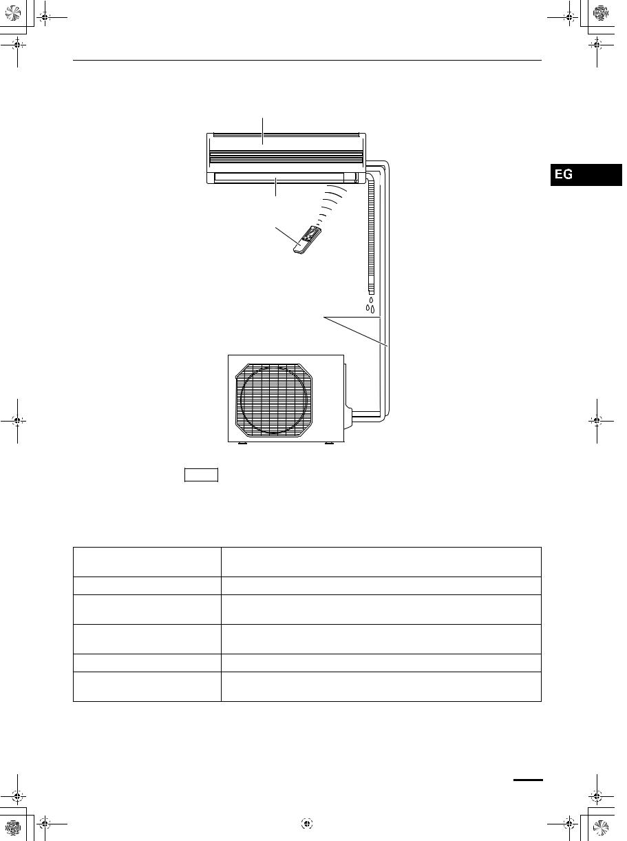
Names of Parts
Air intakes
INDOOR UNIT
Air outlet
Remote control unit
Drain hose 
Refrigerant tubes
OUTDOOR UNIT
Air outlet 
NOTE
This illustration is based on the external view of a standard model. Consequently, the shape may differ from that of the air conditioner which you have selected.
This air conditioner consists of an indoor unit and an outdoor unit. You can control the air conditioner with the remote control unit.
Air Intake Air from the room is drawn into this section and passes through air filters which remove dust.
Air Outlet Conditioned air is blown out of the air conditioner through the air outlet.
Remote Control Unit The wireless remote control unit controls power ON/OFF, operation mode selection, temperature, fan speed, timer setting, and air sweeping.
Refrigerant Tubes The indoor and outdoor units are connected by copper tubes through which refrigerant gas flows.
Drain Hose Moisture in the room condenses and drains off through this hose.
Outdoor (Condensing) Unit The outdoor unit contains the compressor, fan motor, heat exchanger coil, and other electrical components.
OI-671-5EG |
5 |
||
|
|
|
|
|
|
|
|
|
|
|
|
|
|
|
|
 01_SAP-KRV93EH_EN.fm Page 6 Thursday, February 12, 2004 12:10 PM
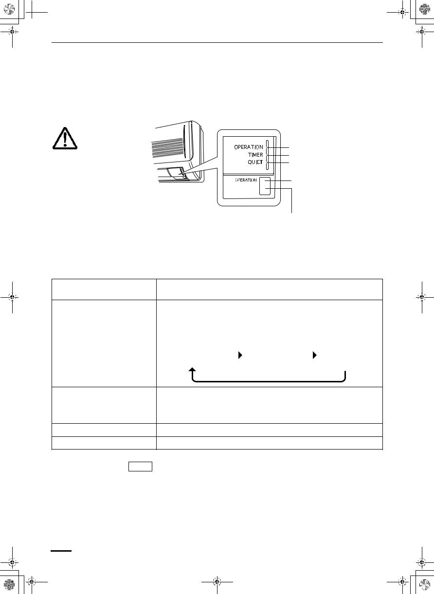
Unit Display and Operation Button
INDOOR UNIT
IMPORTANT
Avoid using radio equipment such as mobile phone near (within 1 m) the remote control receiver. Some radio equipment may cause malfunction of the unit.
If the trouble happens, disconnect power and restart the air conditioner after a few minutes.
OPERATION lamp
TIMER lamp
QUIET lamp
OPERATION button
REMOTE CONTROL receiver
REMOTE CONTROL receiver This section picks up infrared signals from the remote control unit (transmitter).
OPERATION button When the remote control cannot be used, pressing this button enables heating and cooling operation.
Each time this button is pressed, the type of operation conducted is indicated by the changing color of the OPERATION lamp. Press the button and select the lamp color that suits your preference for operation.
Cooling operation |
|
Heating operation |
|
Stop |
|
|
|||
(green) |
|
(red) |
|
(lamp off) |
OPERATION lamp This lamp lights when the system is in the continuous AUTO (red or green), HEAT (red), DRY (orange), COOL (green) and FAN (green) mode.
The OPERATION lamp lights up red and orange alternately when the system is defrosting.
TIMER lamp This lamp lights when the system is being controlled by the timer.
QUIET lamp This lamp lights during operation in the QUIET mode.
NOTE The unit’s display lamps are dimmed during operation in the NIGHT
SETBACK mode.
6 |
OI-671-6-EG |
|

01_SAP-KRV93EH_EN.fm Page 7 Thursday, February 12, 2004 12:10 PM
Remote Control Unit (Display)
Displayed when transmitting data
Displayed when indoor unit sensor is in use
Displayed when setting temperature
Displayed when temperature is shown
Displayed when setting timer
Displayed when the time display is set to 12-hour time.
Symbols
(1)Operation mode
AUTO .....................................
HEAT ......................................
MILD DRY ..............................
COOL .....................................
FAN ........................................
(2)Fan speed
Automatic operation ...............
HIGH .....................................
MEDIUM.................................
LOW .......................................
(3)Temperature setting 16 – 30 °C
When set to 28 °C temperature indication............
(4)Timer
24-hour clock with ON/OFF program Timer........................
ON Timer................................
OFF Timer. .............................
1-hour OFF Timer...................
(5)NIGHT SETBACK ..................
(6)Confirmation of transmission..
(7)Auto. flap indication ................
Flap angle indication ..............
Sweep indication ....................
(8)High power operation .............
(9)Quiet operation.......................
OI-671-7EG |
7 |
||
|
|
|
|
|
|
|
|
|
|
|
|
|
|
|
|
01_SAP-KRV93EH_EN.fm Page 8 Thursday, February 12, 2004 12:10 PM
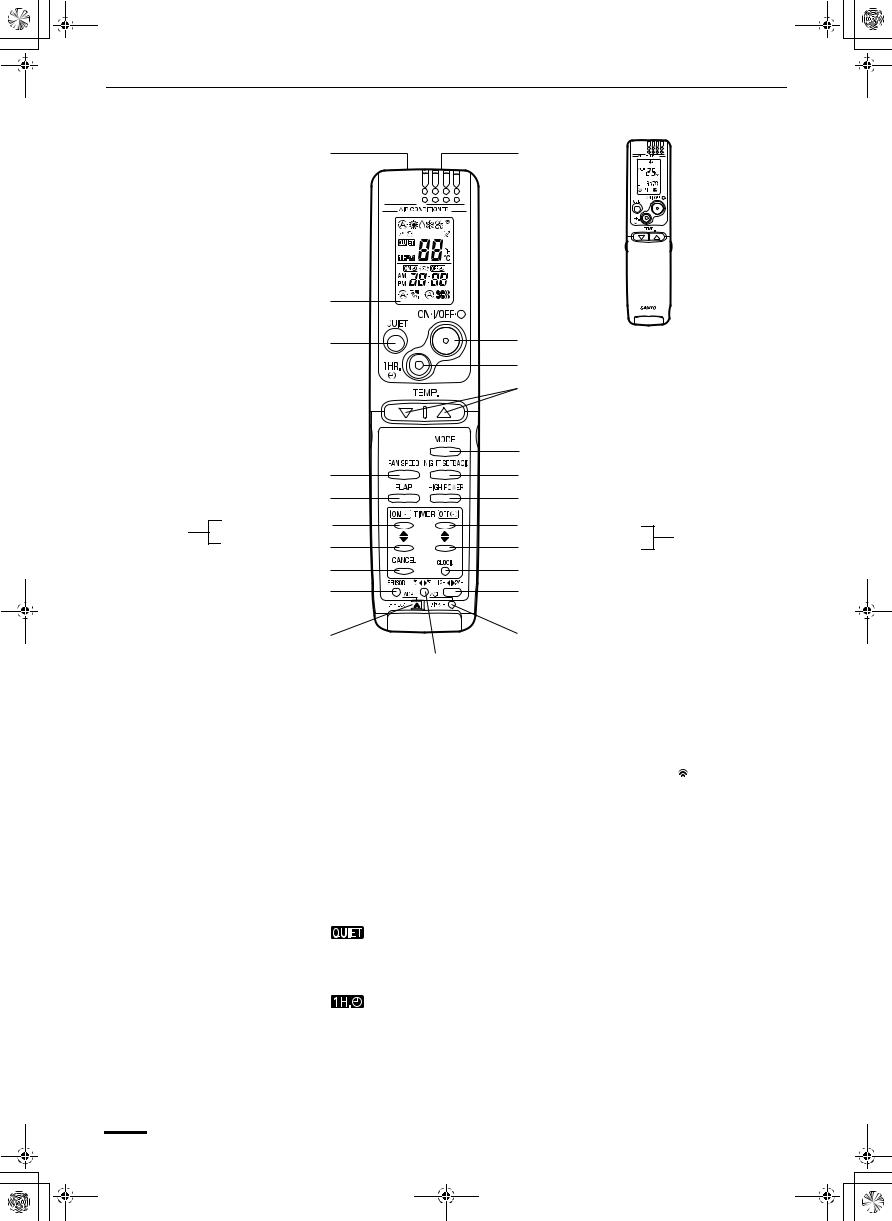
Remote Control Unit
Transmitter |
Sensor |
|
Display |
|
(Cover closed) |
|
|
|
|
||
|
QUIET button |
ON/OFF operation button |
||
|
|
|
||
|
|
1 HR. TIMER button |
|
|
|
|
Temperature setting buttons (TEMP.) |
||
|
|
MODE selector button |
|
|
FAN SPEED selector button |
NIGHT SETBACK button |
|||
|
FLAP button |
HIGH POWER button |
|
|
ON TIME |
Advance button |
Advance button |
OFF TIME |
|
setting |
|
setting |
||
Return button |
Return button |
|||
buttons |
buttons |
|||
|
|
|||
|
CANCEL button |
CLOCK button |
|
|
|
SENSOR button |
Time display selector button |
||
ADDRESS switch |
ACL button |
|
|
|
Temperature display |
|
selector button |
|
NOTE |
|
The illustration above pictures the remote control unit after the cover has |
|
|
|
|
been opened. |
|
|
|
|
||
Transmitter |
When you press the buttons on the remote control unit, the |
mark appears |
||
|
|
|
in the display to transmit the setting changes to the receiver in the air |
|
|
|
|
conditioner. |
|
|
|
|
||
|
Sensor |
A temperature sensor inside the remote control unit senses the room |
||
|
|
|
temperature. |
|
|
|
|
||
|
Display |
Information on the operating conditions is displayed while the remote control |
||
|
|
|
unit is switched on. If the unit is turned off, FLAP setting and FAN SPEED |
|
|
|
|
setting are not displayed. |
|
|
|
|||
QUIET button |
: When you press this button, the fan rotates slower than the fan |
|||
|
|
|
speed setting to provide a quieter operating sound. |
|
|
|
|
||
ON/OFF operation button |
This button is for turning the air conditioner on and off. |
|
||
|
|
|||
1 HR. TIMER button |
: When you press this button, regardless of whether the unit is |
|||
(1-HOUR OFF TIMER) |
operating or stopping, the unit operates for one hour and then shuts |
|||
|
|
|
down. |
|
|
|
|
|
|
8 |
OI-671-8-EG |
|
 Loading...