


8mm CAMCORDER
VP-A50/VP-A52
VP-A55/VP-A57
SERVICE
1. Precautions
2. Reference Information
3. Product Specifications and
Comparison Chart
4. Disassembly and Reassembly
5. Alignment and Adjustment
6. Exploded View and Parts List
7. Electrical Parts List
8. Block Diagrams
9. PCB Diagrams
10. Wiring Diagram
11. Schematic Diagrams
Manual
8mm CAMCORDER
CONTENTS
For mechanical disassembly and adjustment, refer to the “Mechanical Manual”
(DE-6 AD68-30200A).
PUSH
© Samsung Electronics Co., Ltd. MAR. 1997 AD68-20275A

Samsung Electronics 1-1
1. Precautions
1. Be sure that all of the built-in protective devices are
replaced. Restore any missing protective shields.
2. When reinstalling the chassis and its assemblies, be
sure to restore all protective devices, including :
control knobs and compartment covers.
3. Make sure that there are no cabinet openings
through which people--particularly children
--might insert fingers and contact dangerous
voltages. Such openings include the spacing
between the picture tube and the cabinet mask,
excessively wide cabinet ventilation slots, and
improperly fitted back covers.
If the measured resistance is less than 1.0 megohm
or greater than 5.2 megohms, an abnormality exists
that must be corrected before the unit is returned
to the customer.
4. Leakage Current Hot Check (See Fig. 1) :
Warning : Do not use an isolation transformer
during this test. Use a leakage current tester or a
metering system that complies with American
National Standards Institute (ANSI C101.1,
Leakage Current for Appliances), and Underwriters
Laboratories (UL Publication UL1410, 59.7).
5. With the unit completely reassembled, plug the AC
line cord directly the power outlet. With the unitÕs
AC switch first in the ON position and then OFF,
measure the current between a known earth
ground (metal water pipe, conduit, etc.) and all
exposed metal parts, including : antennas, handle
brackets, metal cabinets, screwheads and control
shafts. The current measured should not exceed
0.5 milliamp. Reverse the power-plug prongs in the
AC outlet and repeat the test.
6. X-ray Limits :
The picture tube is designed to prohibit X-ray
emissions. To ensure continued X-ray protection,
replace the picture tube only with one that is the
same type as the original.
Fig. 1 AC Leakage Test
7. Antenna Cold Check :
With the unitÕs AC plug disconnected from the
AC source, connect an electrical jumper across the
two AC prongs. Connect one lead of the ohmmeter
to an AC prong.
Connect the other lead to the coaxial connector.
8. High Voltage Limit :
High voltage must be measured each time
servicing is done on the B+, horizontal deflection
or high voltage circuits.
Heed the high voltage limits. These include the
X-ray protection Specifications Label, and the
Product Safety and X-ray Warning Note on the
service data schematic.
9. Some semiconductor (Òsolid stateÓ) devices are
easily damaged by static electricity.
Such components are called Electrostatically
Sensitive Devices (ESDs); examples include
integrated circuits and some field-effect transistors.
The following techniques will reduce the
occurrence of component damage caused by static
electricity.
10. Immediately before handling any semiconductor
components or assemblies, drain the electrostatic
charge from your body by touching a known
earth ground. Alternatively, wear a discharging
Wrist-strap device. (Be sure to remove it prior to
applying power--this is an electric shock
precaution.)
Device
Under
Test
(Reading should
not be above
0.5mA)
Leakage
Currant
Tester
Earth
Ground
Test all
exposed metal
surfaces
Also test with
plug reversed
(using AC adapter
plug as required)
2-Wire Cord

Precautions
1-2 Samsung Electronics
11. High voltage is maintained within specified limits
by close-tolerance, safety-related components and
adjustments. If the high voltage exceeds the
specified limits, check each of the special
components.
12. Design Alteration Warning :
Never alter or add to the mechanical or electrical
design of this unit. Example : Do not add
auxiliary audio or video connectors. Such
alterations might create a safety hazard. Also, any
design changes or additions will void the
manufacturerÕs warranty.
13. Hot Chassis Warning :
Some TV receiver chassis are electrically
connected directly to one conductor of the AC
power cord. If an isolation transformer is not
used, these units may be safely serviced only if
the AC power plug is inserted so that the chassis
is connected to the ground side of the AC source.
To confirm that the AC power plug is inserted
correctly, do the following : Using an AC
voltmeter, measure the voltage between the
chassis and a known earth ground. If the reading
is greater than 1.0V, remove the AC power plug,
reverse its polarity and reinsert. Re-measure the
voltage between the chassis and ground.
14. Some TV chassis are designed to operate with 85
volts AC between chassis and ground, regardless
of the AC plug polarity. These units can be safely
serviced only if an isolation transformer inserted
between the receiver and the power source.
15. Never defeat any of the B+ voltage interlocks.
Do not apply AC power to the unit (or any of its
assemblies) unless all solid-state heat sinks are
correctly installed.
16. Always connect a test instrumentÕs ground lead to
the instrument chassis ground before connecting
the positive lead; always remove the instrumentÕs
ground lead last.
17. Observe the original lead dress, especially near
the following areas : Antenna wiring, sharp
edges, and especially the AC and high voltage
power supplies. Always inspect for pinched, outof-place, or frayed wiring. Do not change the
spacing between components and the printed
circuit board. Check the AC power cord for
damage. Make sure that leads and components
do not touch thermally hot parts.
18. Picture Tube Implosion Warning :
The picture tube in this receiver employs
Òintegral implosionÓ protection. To ensure
continued implosion protection, make sure that
the replacement picture tube is the same as the
original.
19. Do not remove, install or handle the picture tube
without first putting on shatterproof goggles
equipped with side shields. Never handle the
picture tube by its neck. Some Òin-lineÓ picture
tubes are equipped with a permanently attached
deflection yoke; do not try to remove such
Òpermanently attachedÓ yokes from the picture
tube.
20. Product Safety Notice :
Some electrical and mechanical parts have special
safety-related characteristics which might not be
obvious from visual inspection. These safety
features and the protection they give might be
lost if the replacement component differs from the
original--even if the replacement is rated for
higher voltage, wattage, etc.
Components that are critical for safety are
indicated in the circuit diagram by shading,
( or ).
Use replacement components that have the same
ratings, especially for flame resistance and
dielectric strength specifications. A replacement
part that does not have the same safety
characteristics as the original might create shock,
fire or other hazards.

Samsung Electronics 2-1
2. Reference Information
2-1 Servicing Jigs and Special Tools
2-1-1 Servicing Jigs
Part No.
68140-500-033
Jig Item
Extension
Cable 1
Specification
Pin 44
Main board CCD board
DC/DC Converter board
Remarks
Troubleshooting
Description
CN503 CN901
68140-500-034
Extension
Cable 2
Pin 18
Troubleshooting
CN202
68140-500-036
TP Board -
For VCR section
adjustment
Use for adjustment of VCR section.
(Connect TP Board to connector CTP01 of Main Board)
68140-500-033 68140-500-034 68140-500-035
68140-500-038
Extension Cable 1
Extension Cable 2
Extension Cable 3
Extension Cable 4
68140-500-036
TP Board
68140-500-035
Extension
Cable 3
Pin 40
Troubleshooting
CN203
68140-500-038
Extension
Cable 4
Pin 40
Troubleshooting
CNP01 CND02
Audio board
CN703
CN701

Reference Information
2-2 Samsung Electronics
2-4-2 Extension Cable Connections
2-4-3 TP Board Connections
ASS'Y DC/DC
CONVERTER
EXTENSION CABLE 1
ASS'Y LENS ZOOM
ASS'Y AUDIO BOARD
ASS'Y MAIN BOARD
EXTENSION CABLE 4
EXTENSION CABLE 2
EXTENSION CABLE 3
CN503
CN901
ASS'Y CCD BOARD
CND02
CNP01
CN701
CN203
CN202
CN703
TP BOARD
ASS'Y MAIN BOARD
ASS'Y A/V JACK
VIDEO CABLE
PATTERN GENERATOR
LUMINANCE
OUT
CTP01

Reference Information
Samsung Electronics 2-3
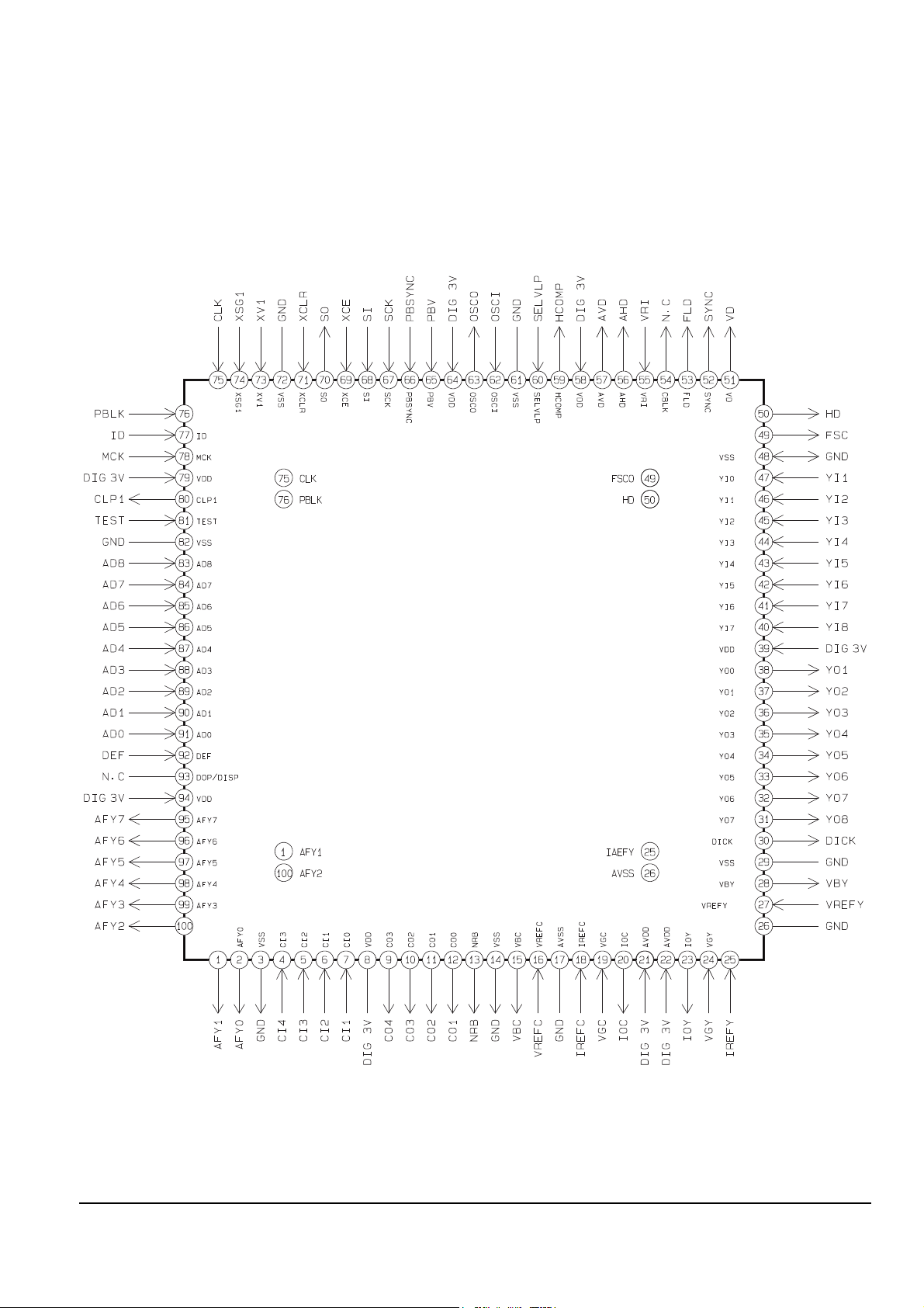
2-2 IC Blocks
2-2-1 IC101(CXA2002R)

Reference Information
2-4 Samsung Electronics
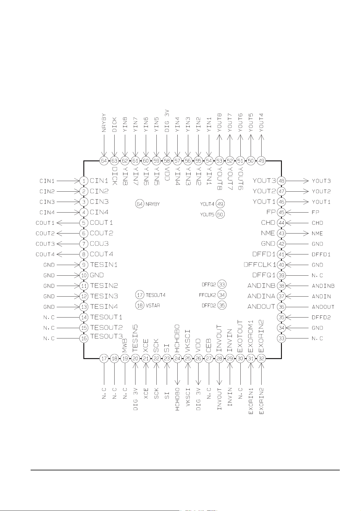
2-2-2 IC102(CXA1509AR)
Reference Information
Samsung Electronics 2-5
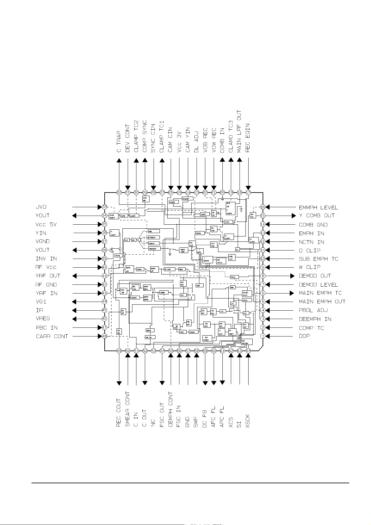
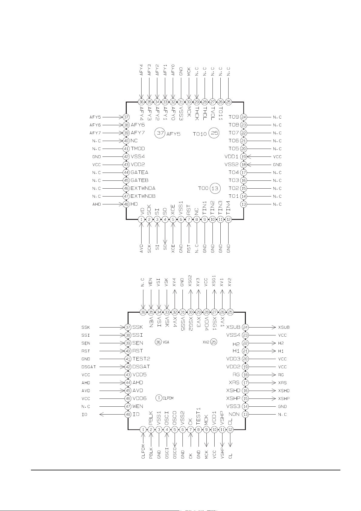
2-2-3 IC201(CXA2080R)
Reference Information
2-6 Samsung Electronics
2-2-4 IC203(CXA2003N)

Reference Information
Samsung Electronics 2-7
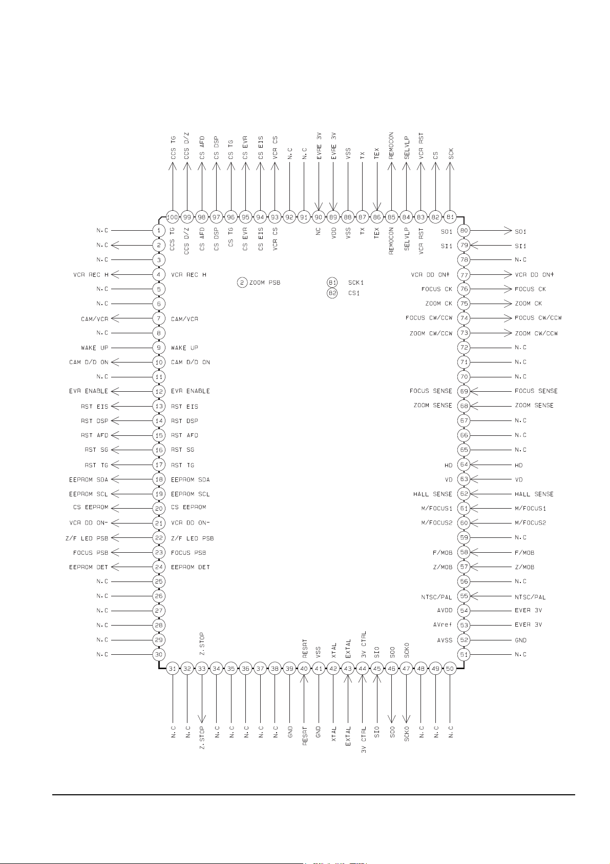
2-2-5 IC501(CXP87452)
Reference Information
2-8 Samsung Electronics
2-2-6 IC502(CXA1814N)
Reference Information
Samsung Electronics 2-9
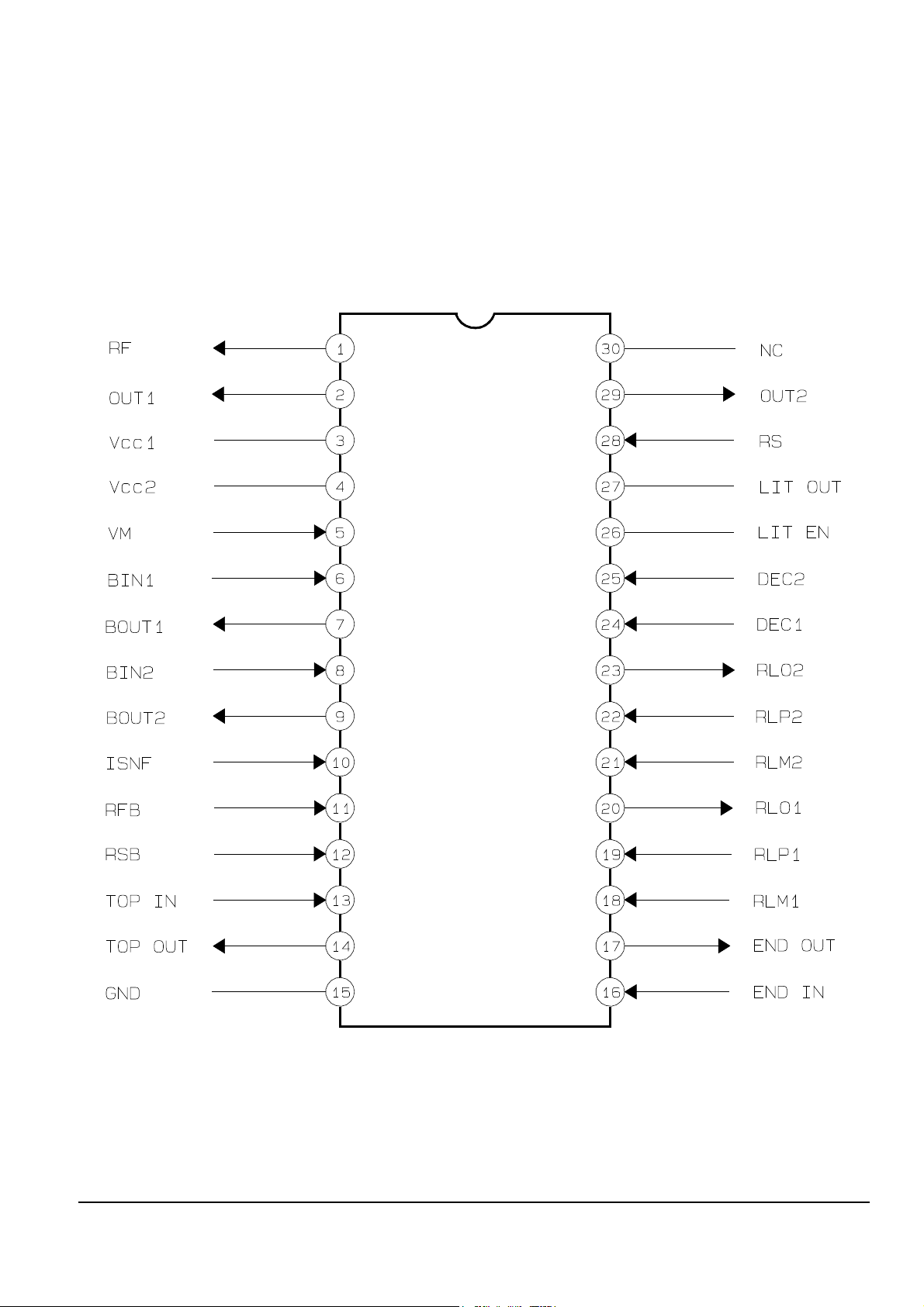
2-2-7 IC503(LB8112M)

Reference Information
2-10 Samsung Electronics
2-2-8 IC701(AN2980)

Reference Information
Samsung Electronics 2-11
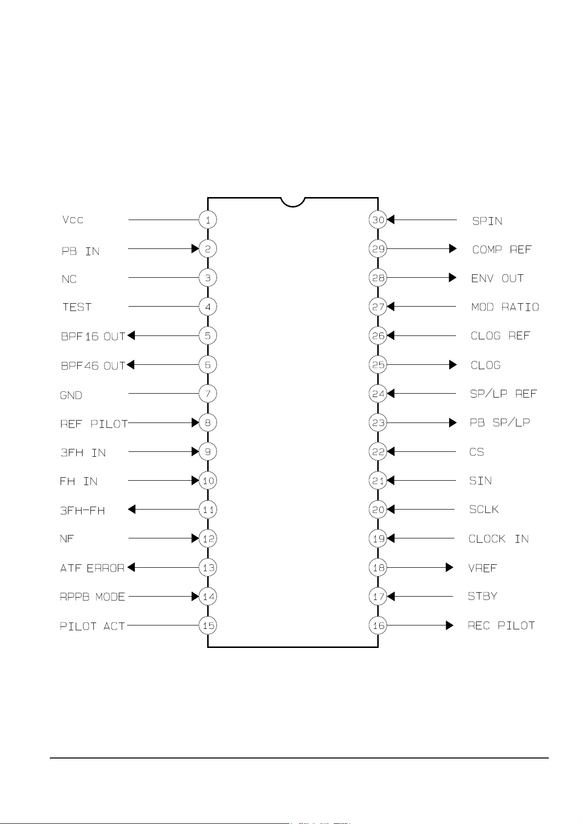
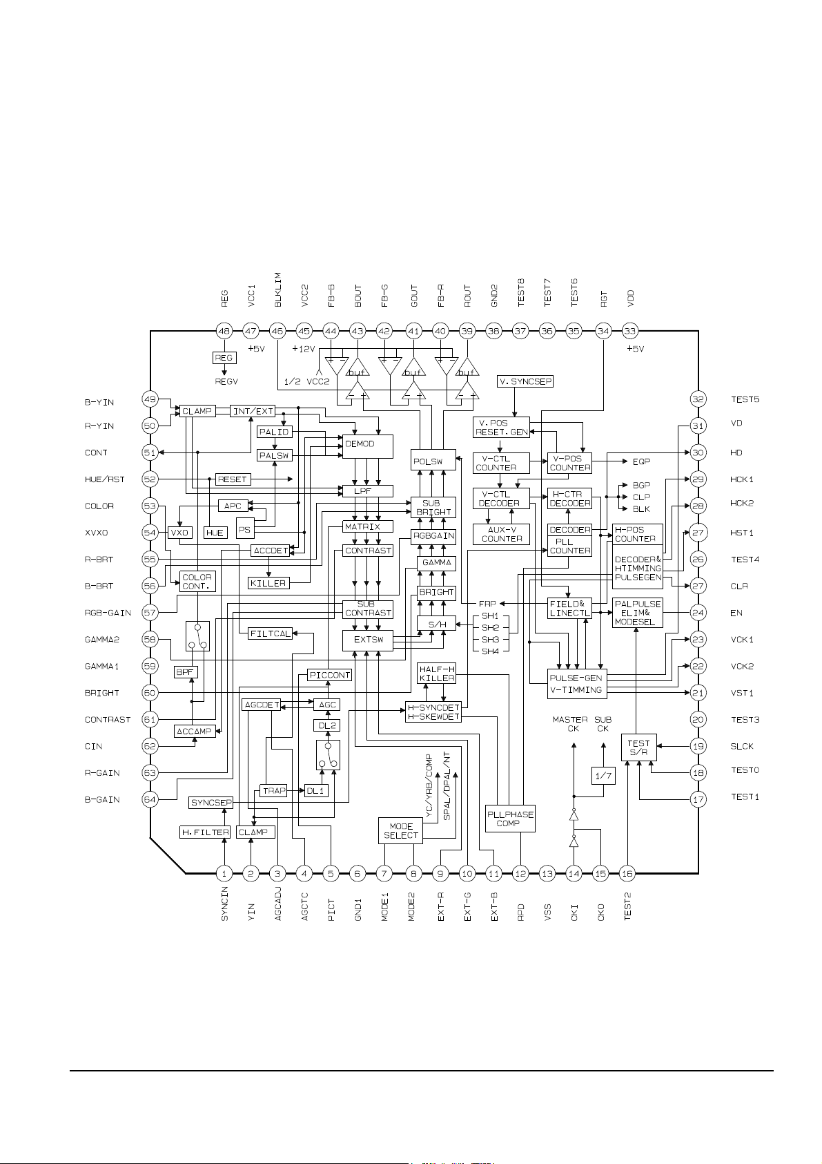
2-2-9 IC761(LA7471M)
Reference Information
2-12 Samsung Electronics
2-2-10 ICC04(CXP87P48AQ)

Reference Information
Samsung Electronics 2-13
2-2-11 ICC06(MPC17AT85ZVM)
Reference Information
2-14 Samsung Electronics
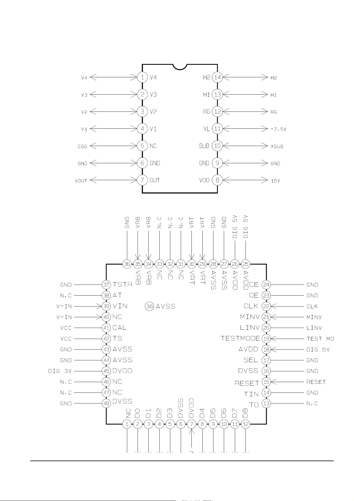
2-2-12 ICD01(ICX071AK)
2-2-13 ICD02(CXD1276AN)
Reference Information
Samsung Electronics 2-15
2-2-14 ICE01(CXA1854AR)-CVF
Reference Information
2-16 Samsung Electronics
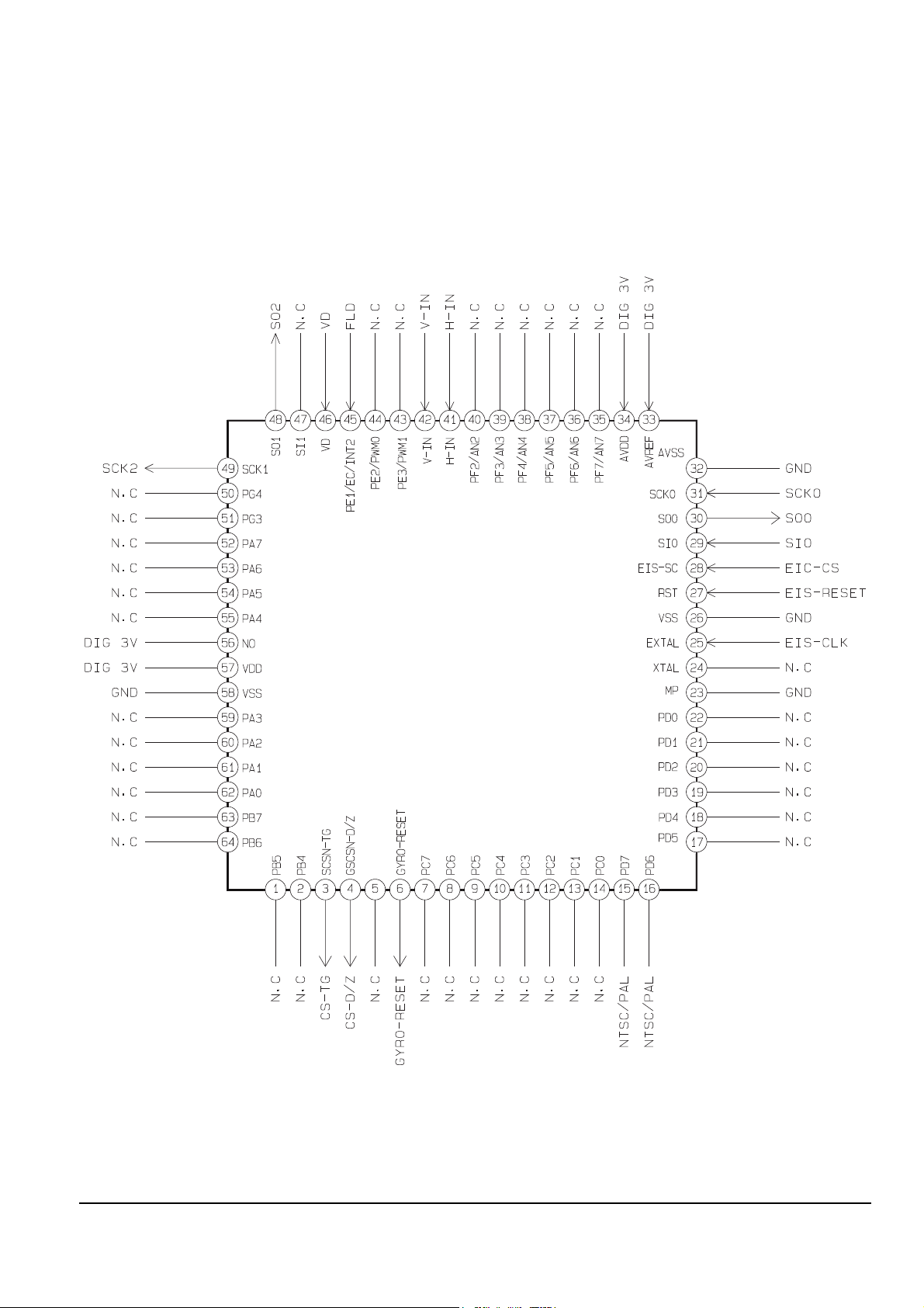
2-2-15 ICE01(CXP81124)-EIS

Reference Information
Samsung Electronics 2-17
2-2-16 ICE01(KA7007)-EVF

Reference Information
2-18 Samsung Electronics
2-2-17 ICP01(CXA2006Q)

Reference Information
Samsung Electronics 2-19
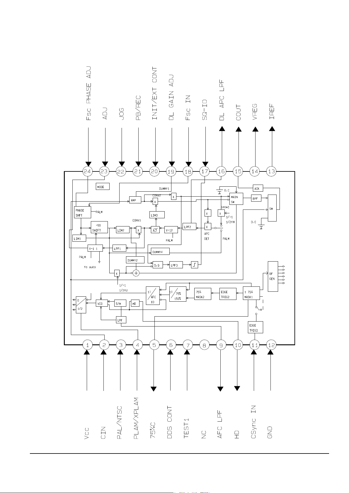
2-2-18 ICP03(CXAD2312R)
Reference Information
2-20 Samsung Electronics
2-2-19 ICP04(CXD2180R)
Reference Information
Samsung Electronics 2-21
2-2-20 ICP05(CXD2153AR)
Reference Information
2-22 Samsung Electronics
2-2-21 ICP06(CXD2418R)
2-2-22 ICP07(CXD2415)
Samsung Electronics 3-1
3. Product Specifications and Comparison Chart
3-1 Product Specifications
Design and specifications are subject to change without notice.
Operation
Description
SYSTEM
Recording systems Video : 2 rotary heads, helical FM scanning
Audio : FM system
Video signal PAL colour, CCIR standard
Cassette format 8 mm / Hi 8 mm
Tape speed SP mode (Standard Play) : approx. 20.051 mm/sec
LP mode (Long Play) : approx. 10.058 mm/sec
Playback time SP mode (Standard Play) : 1 hour 30 minutes (P5-90)
LP mode (Long Play) : 3 hours (P5-90)
Fast-forward/rewind time Approx. 5 min. 40 secs (P5-60)
Image device CCD (Charge Coupled Device)
Viewfinder VP-A50/VP-A55 : Black and White electronic viewfinder
VP-A52/VP-A57 : Colour viewfinder
Lens Combined 16X power zoom lens, f=3.9~62.4mm, F1.4 auto wide macro:
filter diameter 46mm
Automatic focus system Inner
Colour temperature Auto/indoors : 3100°K; outdoor : 5100°K
Lighting > 300 lux (28 footcandles) ; minimum lighting : 3 lux
Aperture correction Automatic with back light adjustment
INPUT/OUTPUT CONNECTORS
Video output Phono jack / S-VIDEO jack, 1Vp-p, 75 ohms, unbalanced, SYNC negative
Audio output Phono jack, 7.5dBs for an output impedance of less than 2.2 Kohms
RFU DC OUT Special mini-jack, 5V DC
Earphone output Minijack, 8 ohms
GENERAL
Power requirement AC power adaptor (7.5V) ; battery pack (6.0V)
Power consumption 5.2W (in camera mode)
Tripod attachment thread Attachment screw less than 9mm long
Microphone Electric condensor microphone, omni-directional, stereo type
Temperature range Operation : 0°C to 40°C (32°F to 104°F); storage : -20°C to 60°C (-4°F to 140°F)
Dimensions/weight Appros. 101 X 109 X 198 mm (3.9 X 4.1 X 7.8 inches) ; approx. 750 g (1.65 lbs)
including lens cap, excluding battery pack and cassette
Product Specifications
3-2 Samsung Electronics
3-2 Comparison Chart
VIEWFINDER EVF CVF EVF CVF
D.ZOOM X X32 D.ZOOM X64 D.ZOOM X64 D.ZOOM
STEREO O O O O
EIS X X O O
WIDE X O O O
MODEL
FUNCTION
VP-A50 VP-A52 VP-A55 VP-A57 REMARK
Samsung Electronics 4-1
4. Disassembly and Reassembly
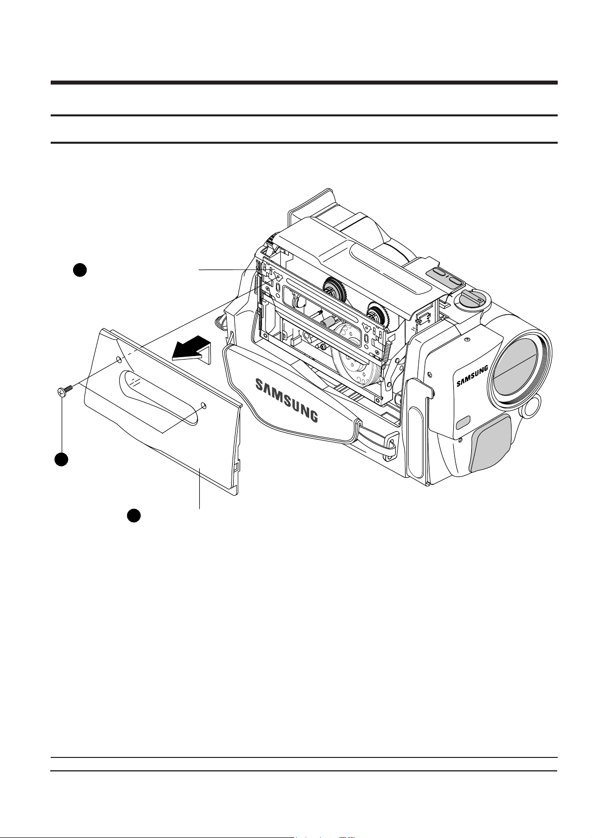
4-1 Cabinet Disassembly
1 APPLY POWER AND OPEN
THE HOUSING ASS'Y.
2 REMOVE 2 SCREWS.
( BH ; M 1.7 X 5 )
3
REMOVE THE ASS'Y COVER HOUSING
IN THE DIRECTION OF ARROW.
4-1-1 Ass’y Cover Housing Removal
Fig. 4-1 Ass’y Cover Housing Removal

Disassembly and Reassembly
4-2 Samsung Electronics
1 REMOVE ASS'Y CASE TOP BY GENTLELY RELEASING
2 LOCKING TABS WITH A SMALL SCREW DRIVER.
(SEE DETAIL "A")
2 LOCKING TABS
PRECISION
SCREW DRIVER
DETAIL "A"
DETAIL "B"
REASSEMBLY : PUT THE 7 TABS INTO THE SLOT, WHILE SLIDING
IT AS SHOWN IN DETAIL "B".
4-1-2 Ass’y Case Top Removal
Fig. 4-2 Ass’y Case Top Removal

Disassembly and Reassembly
Samsung Electronics 4-3
1 REMOVE 3 SCREWS.
( BH ; M2 X 5 )
3 REMOVE THE ASS'Y FRONT
IN THE DIRECTION
OF ARROW .
2 OPEN THE COVER JACK IN
THE DIRECTION OF ARROW .
4 DISCONNECT THE FPC FROM
THE CN702 OF ASS'Y AUDIO BOARD.
1
1
LEVER - BUILT
NOTE : WHEN REASSEMBLING, PUSH THE LEVER - BUILT
TOWARD ARROW AND THEN REINSTALL IT.
C
C
B
A
A
B
4-1-3 Ass’y Front Removal (1)
Fig. 4-3 Ass’y Front Removal (1)
 Loading...