

PLASMA DISPLAY TV
Chassis : D65A(P)
Model : PS42S4SX/XEC
PLASMA DIAPLAY TV CONTENTS
Alignment and Adjustments
Exploded View and Parts List
Service Item
Schematic Diagrams
1.
2.
3.
4.

ELECTRONICS
© Samsung Electronics Co., Ltd. Nov. 2003
Printed in Korea
AA82-01138A
This Service Manual is a property of Samsung Electronics Co.,Ltd.
Any unauthorized use of Manual can be punished under applicable
International and/or domestic law.
Alignment and Adjustments
Samsung Electronics 1-1
1. Alignment and Adjustments
1-1 Service Mode
1-1-1 SERVICE MODE Entry Method (General Transmitter)
¢ For the General Transmitter
1. Turn the power off and set to stand-by mode.
2. Press the buttons of the transmitter in this order; POWER OFF-INFO-MEMO- POWER ON to turn the set on.
3. The set turns on and enters service mode.
¢ For the Factory Transmitter
1. Turn the power on.
2. Press the buttons of the transmitter in this order : Display-Factory.
3. The set enters service mode.
* If you fail to enter service mode, repeat steps 1 and 2 above.
1-1-2 Initial DISPLAY State of SERVICE MODE
1-1-2(A) OSD DISPLAY
1-1-2(B) Button Operations in SERVICE MODE
☞ Indicates selected input mode
☞ Picture Adjustment
☞ Setting the Initial Values
☞ Setting the Special Features
☞ Options-1 : Options of the Product Particulars
☞ Options-2 : Options of the PDP Properties
☞ Initializing after saving the adjustments
☞ Software Version Information
Factory Mode Current Input Mode
01. Picture Improvement √
02. Initial Setting √
03. PIP/TTX/Test Pattern √
04. Option-1 √
05. Option-2 √
06. Reset √
Release : 2003-10-27-15:40
Version : T_MOZMEU_0086
Menu Displays all menus
UP/DOWN Cursor move to select items
LEFT/RIGHT Enable to increase and decrease the data of the selected items
(ENTER) Confirm your choice(Store OR Enter)
Alignment and Adjustments
1-2 Samsung Electronics
1-2 WHITE Balance Coordinates
1-2-1 PS42S4S White Balance Adjustment
1. W/B Adjustment is required for the following four modes: DVI-> COMPONENT-> PC->VIDEO
2. Adjustment Method
(Signal equipment : MSPG-925LTH, Measurement equipment : CA210)
(1) Adjust the target set by adjusting the panel logic and the video DNIe adjustment register in
order to determine the referential W/B of the panel with a DVI input, which is the full digital path.
(2)For Component adjustment, adjust the adjustment register of AD9883 to align the DTV signal
to the DNIe and logic panel value which was fixed with a DVI adjustment so that they are
in effect considered to be the same signals. (At this time, do not adjust the gain of AD9883 -> the Highlight W/B does not
need to be adjusted since its deviation falls within valid distribution range.)
(3)PC adjustment is same as Component adjustment. (The offset can be applied to the values obtained through DTV adjustment.
However, additional adjustment is required for Y, Cb, and Cr of Component since PC processes R, G, and B signals.)
* Attention for Component/PC adjustment
- Load the Auto color pattern. (Pattern #21)
- Excute Auto color of factory mode to adjust gain and offset.
- Load the Toshiba Pattern.(Pattern #16) and then adjust W/B.
(4)Video adjustment is performed with the Toshiba pattern (in-house signal) and differs from the VG828 signals in the above three
modes. Hence, it should be performed with the same method of (1) DVI adjustment.
Also, Video adjustment should be performed with Video port and Graphic port separately.
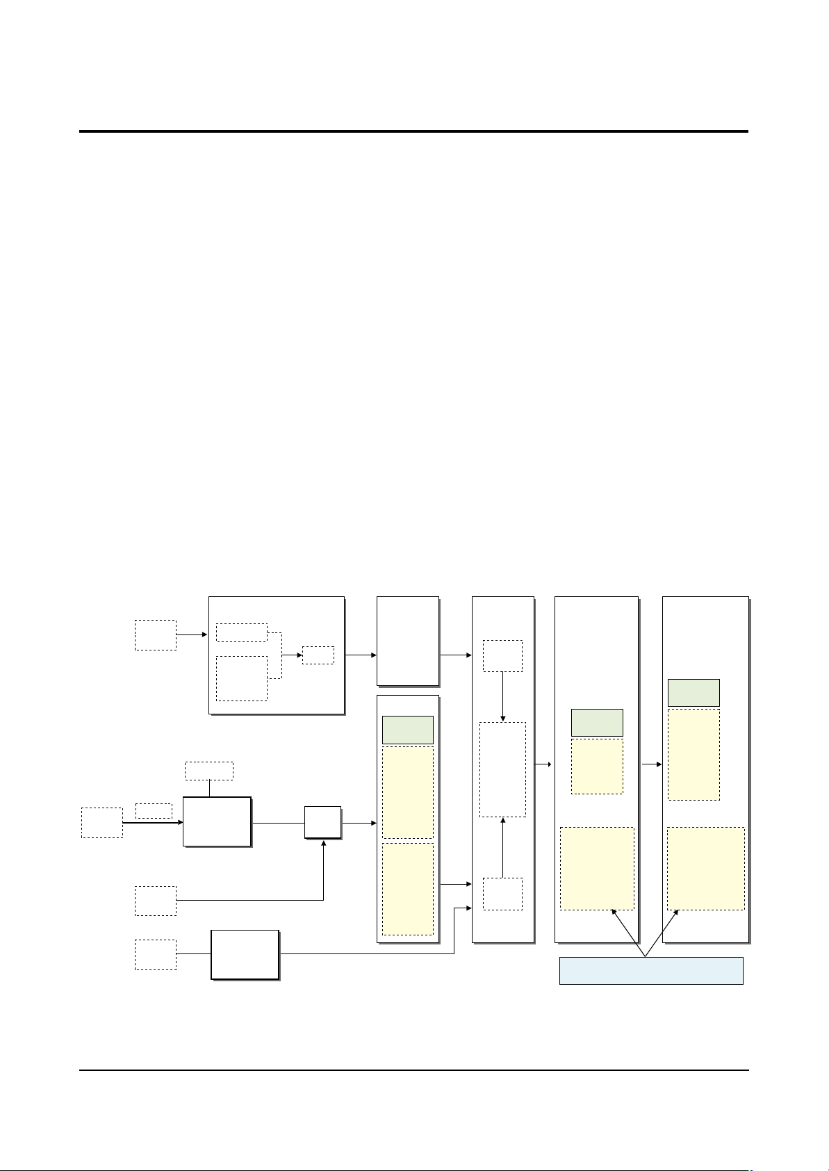
* Thus, Micom saves the W/B data separately for each memory mode of the block (See the block diagram given below) during W/B
adjustment.
DTV
COMP1,2
RF
VIDEO
YPbPr
PC
(A-RGB)
DVI
(D-RGB)
TTX-mode
CXA2101
VSP9437 FLI2310
V-PEAKING
RGB
Scaler
SW
RGB/YUV
CONTRAST
BRIGHT
IC
RGB
SIL169
Y-Delay
C-Delay
Brightness
Contrast
Saturation
AD9883
Adjustment
Reg
Y/R-gain
Cr/B-gain
Cb/G-gain
Y/R-offset
Cr/b-offset
Cb/G-offset
Memory
Mode
Analog PC
- Auto Color
value(RGB)
DTV Mode
ASI510
Video
Port
RGB-cont
RGB-bri
R-gamma
G-gamma
B-gamma
Graphic
Port
DNIe
Adjustment
Reg
Bri-offset
Con-offset
Memory
Mode
- DVI
- PC
- Video
- Component(DTV)
Different adjustment values will be applied
to DVI, PC ,DTV(Component) and Video, mode.
Logic
Adjustment
Reg
R-dri
G-dri
B-dri
R-cutoff
G-cutoff
B-cutoff
Memory
Mode
- DVI
- PC
- Video
- Component(DTV)
Alignment and Adjustments
Samsung Electronics 1-3
1-3-1 Factory OSD Main Menu
1-3 Factory Data
☞ Indicates selected input mode
☞ Picture Adjustment
☞ Setting the Initial Values
☞ Setting the Special Features
☞ Setting the Options of the Product Particulars
☞ Setting the Options of the PDP Properties
☞ Initializing after saving the adjustments
☞ Software Version Information
01.Picture Improve
Factory Mode Current Input Mode
01. Picture Improvement √
02. Initial Setting √
03. PIP/TTX/Test Pattern √
04. Option-1 √
05. Option-2 √
06. Reset √
Release : 2003-10-27-15:40
Version : T_MOZMEU_0086
☞ White Balance Adjustment
☞ Color Adjustment
☞ Contrast & Brightness Enhancement
☞ Detail Enhancement Sharpness Adjustment
☞ Y/C Delay Setting according to the System and
Input Modes
☞ Motion Enhancing Adjustment
☞ DNIe Registers
☞ Logic Registers of the Panel
☞ Picture Size Registers
01.Picture Improvement Current Input Mode
01. White Balance √
02. Color √
03. Cont/Bri Enhancement √
04. Detail Enhancement √
05. Y/C Delay √
06. Motion √
07. DNIe √
08. Logic √
09. Picture Size √
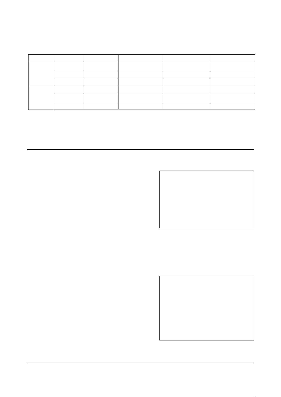
H/L
L/L
x
y
Y(fL)
x
y
Y(fL)
VIDEOI
285
295
38.5
285
295
2.2
Component
285
295
41.0
285
295
0.9
PC
285
295
33.5
285
295
0.5
DVI
285
295
40.0
285
295
0.9
1-2-2 White Balance Coordinates by Mode

Alignment and Adjustments
1-4 Samsung Electronics
01.Picture Improve => 01.White Balance Adjustment
01.White Balance
01.R Drive
02.G Drive
03.B Drive
04.R Cutoff
05.G Cutoff
06.B Cutoff
07.Sub Contrast
08.Sub Brightness
09.R Gain
10.G Gain
11.B Gain
12.R/Cr Offset
13.G/Y Offset
14.B/Cb Offset
15.Auto color
TV
140
128
120
128
128
128
37
54
X
X
X
X
X
X
on/off
Mode-1
140
128
120
128
128
128
W/B
W/B
x
x
x
x
x
x
x
Mode-2
140
128
120
128
128
128
W/B
W/B
142
142
142
60
48
64
O
Mode-3
140
128
120
128
128
128
W/B
W/B
142
142
142
60
48
64
O
Mode-4
140
128
120
128
128
128
W/B
W/B
x
x
x
x
x
x
x
Initial Values of Input Modes
Video
Component PC DVI
Relevant IC
Logic
DNIe
AD9883
ITEM
❈ Input modes require respective storing the changes after adjustment.
01~06 : Logic
07~08 : DNIe
09~15 : AD9883

Alignment and Adjustments
Samsung Electronics 1-5
01.Picture Improve => 02.Color Adjustment
02.Color
01.U-Saturation
02.V-saturation
03.RGB/YUV U-SAT
04.RGB/YUV V-SAT
05.RGB/YUV Tint
06.FLI-saturation
07.R Gamma
08.G Gamma
09.B Gamma
10.Gain-Sel
11.Cr Gain
12.Cb Gain
13.Y Gain
TV
36
36
22
22
3
132
30
30
30
1
7
7
1
Mode-1
36
36
22
22
3
132
30
30
30
1
7
7
1
Mode-2
x
x
x
x
x
x
x
x
x
x
x
x
x
Mode-3
x
x
x
x
x
x
x
x
x
x
x
x
x
Mode-4
x
x
x
x
x
x
x
x
x
x
x
x
x
Initial Values of Input Modes
PC DVI
Relevant IC
VSP9437
FLI2310
ASI510
CXA2151Q
ITEM
01 ~05 : VSP9437
07~09 : ASI510
06 : FLI2310
10~13 : CXA21510
Video
Component
 Loading...