

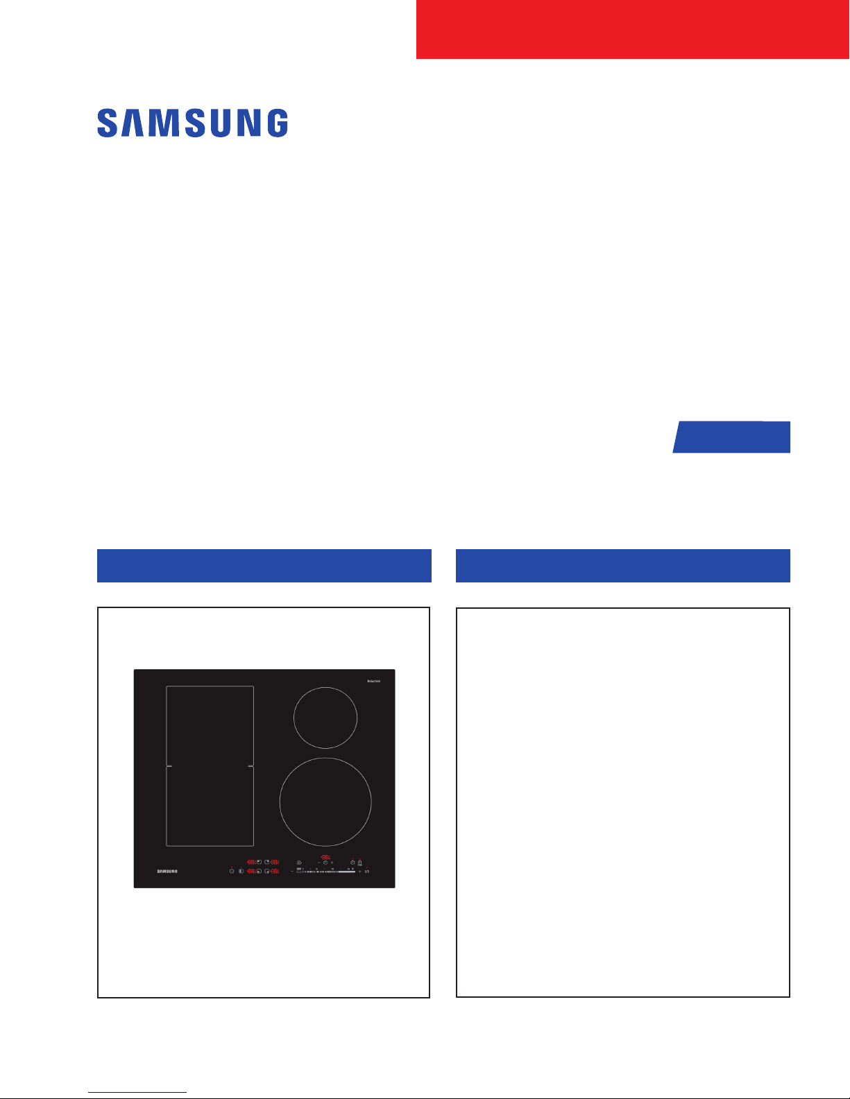
INDUCTION HOB
BASIC : NZ63K7777BK
MODEL : NZ64K5747BK
MODEL CODE : NZ64K5747BK/EF
Manual
SERVICE
NZ64K5747BK/EU
NZ64K5747BK/EO
NZ64K5747BK/EE
NZ64K5747BK/WT
NZ64K5747BK/ET
INDUCTION HOB CONTENTS
INDUCTION HOB
1. Precaution
2. Product Specication
3. Disassembly and Reassembly
4. Troubleshooting
5. PCB Diagrams
6. Wiring Diagrams
NZ64K5747BK

Contents
Contents
1. General Safety Precautions. . . . . . . . . . . . . . . . . . . . . . . . . . . . . . . . . . . . . . . . . . . . . . . . . . . . . . . . . . . . . . . . 1
2. Specications . . . . . . . . . . . . . . . . . . . . . . . . . . . . . . . . . . . . . . . . . . . . . . . . . . . . . . . . . . . . . . . . . . . . . . . . . . 2
2-1 Induction Heating . . . . . . . . . . . . . . . . . . . . . . . . . . . . . . . . . . . . . . . . . . . . . . . . . . . . . . . . . . . . . . . . . . . . 2
2-2 Features . . . . . . . . . . . . . . . . . . . . . . . . . . . . . . . . . . . . . . . . . . . . . . . . . . . . . . . . . . . . . . . . . . . . . . . . . . . 2
2-3 Table of Specication . . . . . . . . . . . . . . . . . . . . . . . . . . . . . . . . . . . . . . . . . . . . . . . . . . . . . . . . . . . . . . . . . 3
2-4 Accessory . . . . . . . . . . . . . . . . . . . . . . . . . . . . . . . . . . . . . . . . . . . . . . . . . . . . . . . . . . . . . . . . . . . . . . . . . . 4
2-5 Installing the hob . . . . . . . . . . . . . . . . . . . . . . . . . . . . . . . . . . . . . . . . . . . . . . . . . . . . . . . . . . . . . . . . . . . . 5
3. Disassembly and Reassembly . . . . . . . . . . . . . . . . . . . . . . . . . . . . . . . . . . . . . . . . . . . . . . . . . . . . . . . . . . . . . 8
3-1 Tools for Removal and Reassembly . . . . . . . . . . . . . . . . . . . . . . . . . . . . . . . . . . . . . . . . . . . . . . . . . . . . . . 8
3-2 Replacement of the Assy Top Plate . . . . . . . . . . . . . . . . . . . . . . . . . . . . . . . . . . . . . . . . . . . . . . . . . . . . . . 9
3-3 Replacement of the Assy Control Panel . . . . . . . . . . . . . . . . . . . . . . . . . . . . . . . . . . . . . . . . . . . . . . . . . . . 9
3-4 Replacement of the Working Coil . . . . . . . . . . . . . . . . . . . . . . . . . . . . . . . . . . . . . . . . . . . . . . . . . . . . . . 10
3-5 Replacement of the PBA . . . . . . . . . . . . . . . . . . . . . . . . . . . . . . . . . . . . . . . . . . . . . . . . . . . . . . . . . . . . . 12
3-6 Replacement of the POWER CABLE . . . . . . . . . . . . . . . . . . . . . . . . . . . . . . . . . . . . . . . . . . . . . . . . . . . . 14
4. Troubleshooting . . . . . . . . . . . . . . . . . . . . . . . . . . . . . . . . . . . . . . . . . . . . . . . . . . . . . . . . . . . . . . . . . . . . . . . . 15
4-1 Part Checking method . . . . . . . . . . . . . . . . . . . . . . . . . . . . . . . . . . . . . . . . . . . . . . . . . . . . . . . . . . . . . . . 15
4-2 DEMO mode . . . . . . . . . . . . . . . . . . . . . . . . . . . . . . . . . . . . . . . . . . . . . . . . . . . . . . . . . . . . . . . . . . . . . . 16
4-3 Failure Codes . . . . . . . . . . . . . . . . . . . . . . . . . . . . . . . . . . . . . . . . . . . . . . . . . . . . . . . . . . . . . . . . . . . . . . 17
4-4 Electrical Malfunction . . . . . . . . . . . . . . . . . . . . . . . . . . . . . . . . . . . . . . . . . . . . . . . . . . . . . . . . . . . . . . . . 28
4-5 Auto Function Check Test . . . . . . . . . . . . . . . . . . . . . . . . . . . . . . . . . . . . . . . . . . . . . . . . . . . . . . . . . . . . 30
5. P.C.B Diagrams . . . . . . . . . . . . . . . . . . . . . . . . . . . . . . . . . . . . . . . . . . . . . . . . . . . . . . . . . . . . . . . . . . . . . . . . 31
5-1 P.C.B Diagrams : Touch (Control) PCB . . . . . . . . . . . . . . . . . . . . . . . . . . . . . . . . . . . . . . . . . . . . . . . . . . 31
5-2 P.C.B Diagrams : SMPS PCB . . . . . . . . . . . . . . . . . . . . . . . . . . . . . . . . . . . . . . . . . . . . . . . . . . . . . . . . . 32
5-3 P.C.B Diagrams : Inverter PCB . . . . . . . . . . . . . . . . . . . . . . . . . . . . . . . . . . . . . . . . . . . . . . . . . . . . . . . . 33
6. Wiring Diagrams . . . . . . . . . . . . . . . . . . . . . . . . . . . . . . . . . . . . . . . . . . . . . . . . . . . . . . . . . . . . . . . . . . . . . . . 35
This document can not be used without Samsung’s authorization.
1. General Safety Precautions
1. Information contained in this manual is intended for
use by a qualied service technician. The technician
is required to be familiar with proper and safe procedures to be followed when repairing appliance.
All tests and repairs are to be performed using
proper tools and measuring devices. All component
replacements should be made using only factory
approved replacement parts.
2. Electrical shock and injury can result if service or
repairs are attempted by an unqualied individual.
Improper disassembly, assembly or adjustments
can create hazardous conditions.
3. Even for a skilled technician, a risk of injury or
electrical shock exists while performing service or
repairs. Electrical injury can be serious or fatal.
Extreme caution must taken when performing
voltage checks on individual components of an
appliance.
NOTE
Except as necessary to perform a particular
step in servicing a product, the electrical power
supply should always be disconnected when
servicing a product.
4. To avoid possible injury, the appliance must be
properly grounded. Never plug in or direct wire an
appliance unless it is properly grounded. See the
installation instructions that originally accompanied the product for proper grounding procedures.
5.The ventilation gap between the worktop and front of
the unit underneath it must not be covered.
8. The hob is to be connected to the mains using a
device that allows the appliance to be disconnected
from the mains at all poles with a contact opening
width of at least 3 mm, eg. automatic line protecting
cut - out, earth leakage trips or fuse.
9. Pay attention (conformity) to phase and neutral
allocation of house connection and appliance
(connection schemes); otherwise, components can
be damaged.
Warranty does not cover damage resulting from
improper installation.
If the supply cord is damaged, it must be replaced
by a special cord or assembly available from the
manufacturer or its service agent.
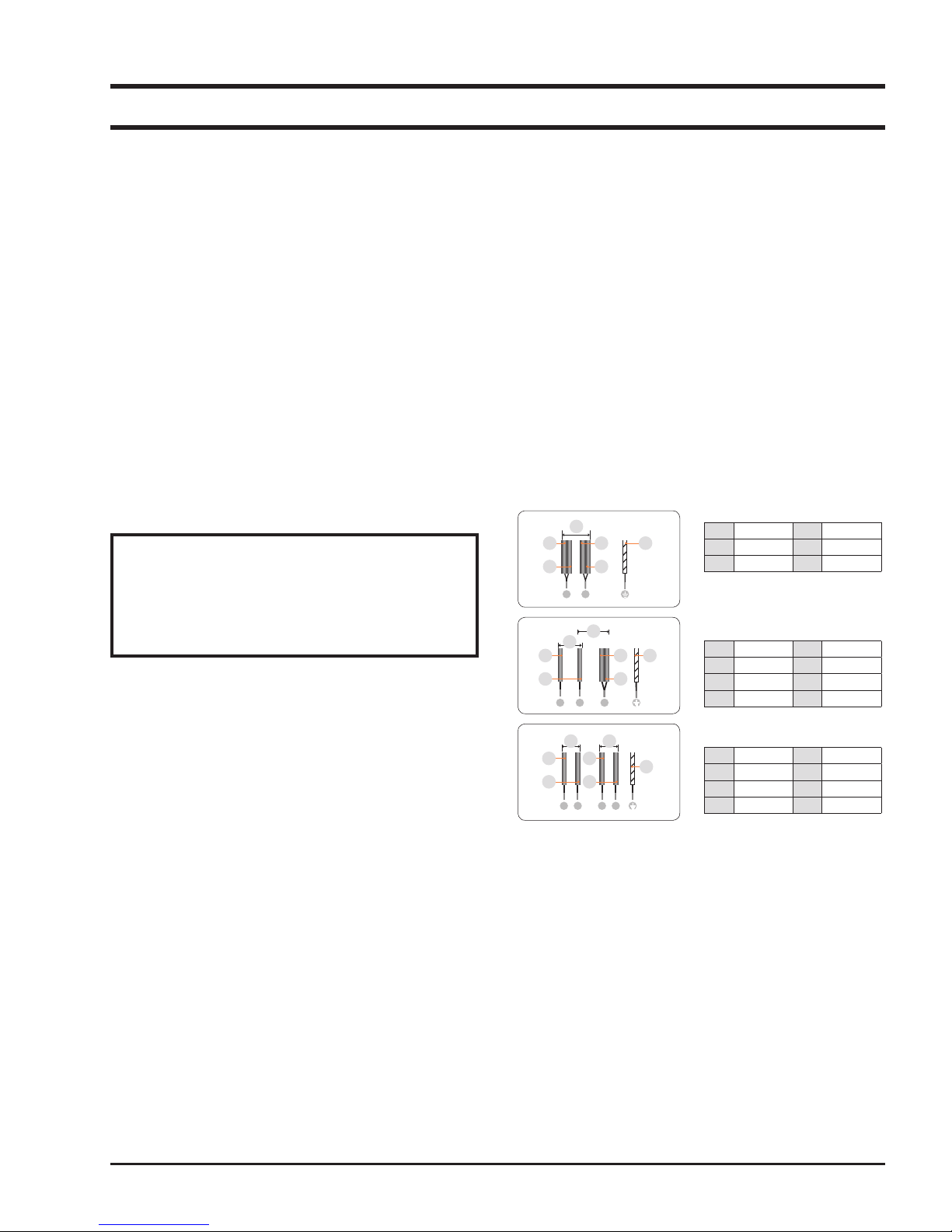
1N~ (32A)
220-240 V ~
01
Brown
02
Black
03
2N~ (16A): Separate the 2-phase wires
(L1 and L2) before connection.
220-240 V ~
01
380-415 V ~
02
Brown
03
Black
04
2 x 1N~ (16A): Separate the wires before
01
02
03
04
connection.
220-240 V ~
Brown
Blue
220-240 V ~
04
05
06
05
06
07
05
06
07
Blue
Gray
Green/Yellow
Blue
Gray
Green/Yellow
Black
Gray
Green/Yellow
02
03
L N
02
03
04
L1 L2 N
01 04
02
03
L1 N1 L1 N2
01
01
05
06
04 06
05
05
06
07
07
6. Before connecting, check that the nominal voltage
of the appliance, that is, the voltage stated on the
rating plate, corresponds to the available supply
voltage. The rating plate is located on the lower
casing of the hob.
7. The heating element voltage is AC230V~. The
appliance also works perfectly on networks with
AC220V~ or AC240V~.
- 1 -
This document can not be used without Samsung’s authorization.
2. Specications
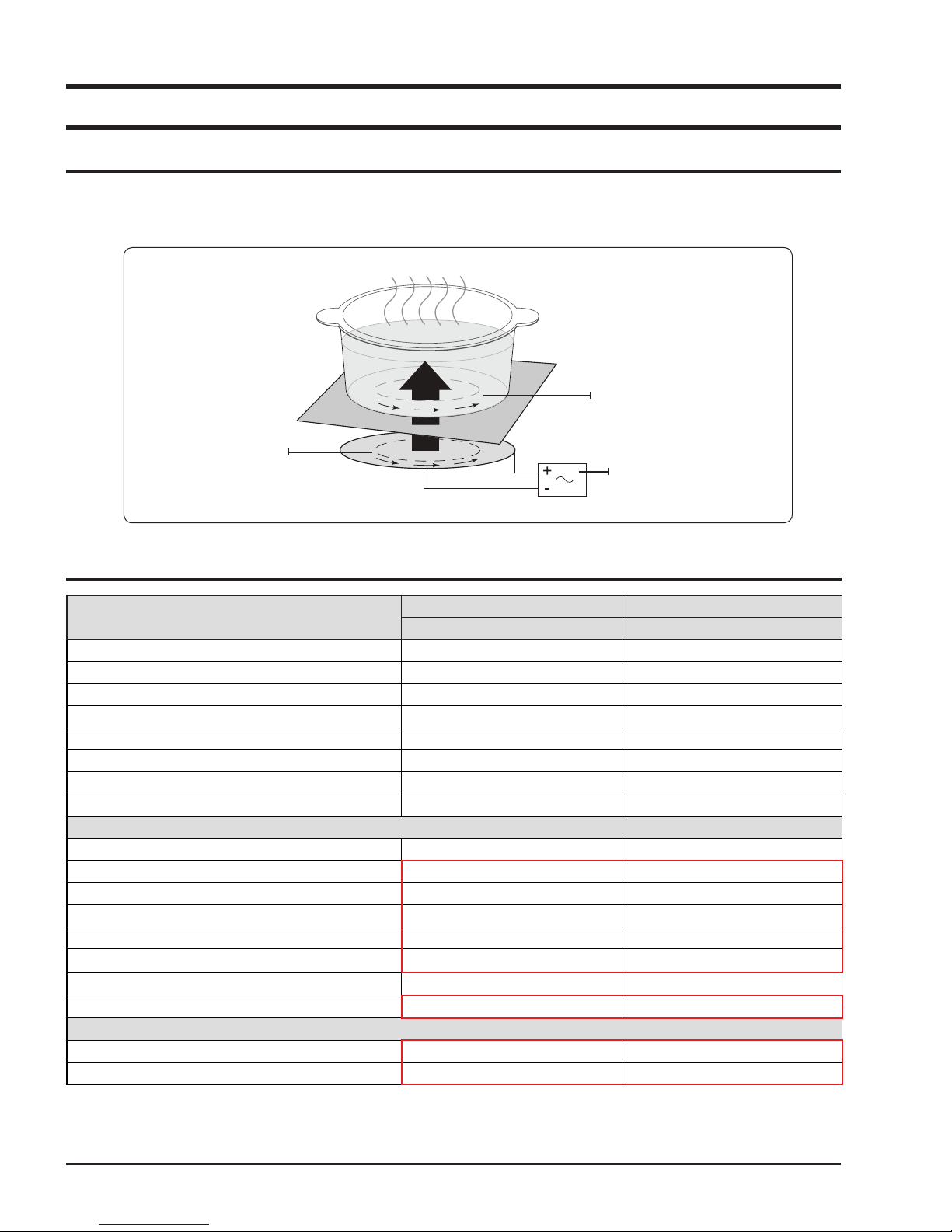
2-1 Induction Heating
• The Principle of Induction Heating: When you place your cookware on a cooking zone and you turn it on, the electronic
circuits in your induction hob produce “induced currents” in the bottom of the cookware which instantly raise cookware’s
temperature.
Induced currents
Induction coil
Electronic circuits
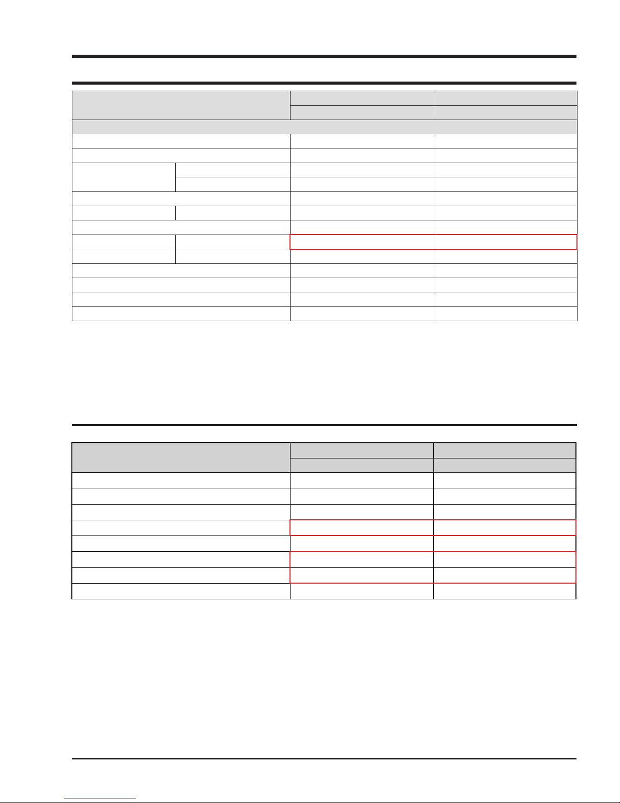
2-2 Features
Model Name
Product Type Induction Hob Induction Hob
Glass Ceramic Glass Ceramic Glass
Control Method Touch Sensor Touch Sensor
Residual Heat Indicator Yes Yes
Safety Shutoff Yes Yes
Pan Detection Yes Yes
Install Type Built-In Built-In
Design 1Bevel 1Bevel
Electric Features
Burner Power
Front Left 1,800W/Boost 2,600W
Rear Left 1,800W/Boost 2,600W
Flex Front 1,800W/Boost 2,600W
Flex Rear 1,800W/Boost 2,600W
Rear Right - 1,400W/Boost 2,000W
Front Right 2,200W/Boost 3,200W 2,200W/Boost 3,200W
Flex zone 3,300W/Boost 3,600W 3,300W/Boost 3,600W
Burner Size
Rear Right - 145mm
Front Right 200mm 210mm
Basic Model New Model
NZ63J9770EK NZ64K5747BK
- 2 -
2. Specications
This document can not be used without Samsung’s authorization.
Model Name
Control Features
Sound on/off Headen Lock Yes Yes
Power Level 1~15 level 1~15 level
Timer
Power Control 15+Booster 15+Booster
Direct Access +/-1 Yes Yes
Power On/Off Yes Yes
Ready Pan Flex Zone Yes No
Keep Warm +/-1 Yes Yes
Pause Yes Yes
Quick Start Yes Yes
Quick Stop Yes Yes
Demo Mode Yes Yes
Kichen Timer Yes Yes
Alarm Yes Yes
Basic Model New Model
NZ63J9770EK NZ64K5747BK
2-3 Table of Specication
Model Name
Electrical Connection 220~240V, 50/60Hz 220~240V, 50/60Hz
Rated voltage 2N : 380~415V, 50/60Hz 2N : 380~415V, 50/60Hz
Mains-connection 1N : 220~240V, 50/60Hz 1N : 220~240V, 50/60Hz
Output Power Max 6,800W Max 7,200W
"Outside Dimensions (WxLxH)" 600 x 520x 56 mm 600 x 520x 56 mm
Net Weight 13.5kg 12.7kg
Gross Weight 16.5kg 15.5kg
Export Zone EU EU
Basic Model New Model
NZ63J9770EK NZ64K5747BK
- 3 -
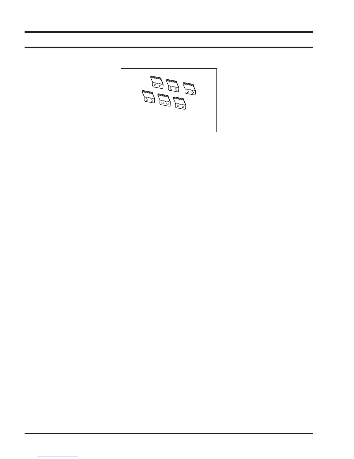
2-4 Accessory
This document can not be used without Samsung’s authorization.
Bracket Spring
- 4 -
This document can not be used without Samsung’s authorization.
01
02
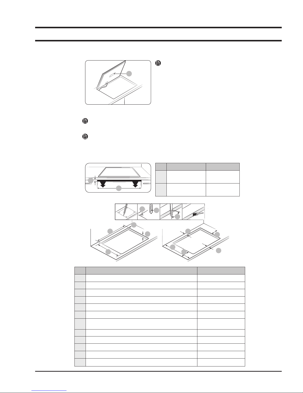
2-5 Installing the hob
2-5-1 Installing into the countertop
A
A. Serial number
NOTE
Pay special attention to the minimum space and clearance requirements.
NOTE
The bottom of the hob is equipped with a fan. If there is a drawer under the hob
it should not be used to store small objects or paper, since they could damage the
fan or interfere with the cooling if they are sucked into it.
NOTE
Make a note of the serial number on the
appliance rating label prior to installation.
This number will be required in the case
of requests for service and is no longer
accessible after installation, as it is on the
original rating plate on the underside of the
appliance.
No. Explanation Size
01 Height of
ventilation hole
02 Width of
ventilation hole
Min 2 mm
560 mm
01
02
03
06
10
08
11
12
Max 50 mm,
Min 20 mm
04
05
No. Explanation Size
01 Check 4 Point
02 Drill diameter Ø 6
03 Right angle of cutting point 90 °
04 Width Size 560±1 mm
05 Height Size 490±1 mm
06 Curve Size R3
07 Size of table thickness
08 Distance between end of table and cutting point (Top-side) Min 60 mm
09 Height of table Min 600 mm
10 Distance between end of table and cutting point (Left-side) Min 60 mm
11
Distance between end of table and cutting point (Right-side) Min 60 mm
12 Distance between end of table and cutting point (Bottom-side) Min 50 mm
07
09
- 5 -
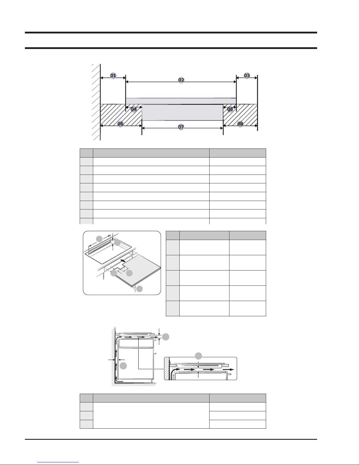
2-5 Installing the hob
06
07
08
04
02
05
01
03
05
02
01
03
04
No. Explanation Size
01 Distance between wall and Induction Min 40 mm
02 Size of depth of Induction 520 mm
03 Distance between Induction and end of table Min 40 mm
04 Distance between glass and case burner 25 mm
05 Distance between glass and case burner 15 mm
06 Distance between wall and case burner. Min 60 mm
07 Size of depth of case burner 480 mm
This document can not be used without Samsung’s authorization.
No. Explanation Size
01 Width of rear
ventailation
02 Height of rear
ventaliation
03 Depth of power
cord path
04 Width of power
cord path
05 Height of block
board
Min 550 mm
Min 35 mm
Min 65 mm
Min 100 mm
Min 5 mm
02
01
No. Explanation Size
01
02 Min 2 mm
03 Min 20 mm
Size of Ventaliation
03
Min 20 mm
- 6 -
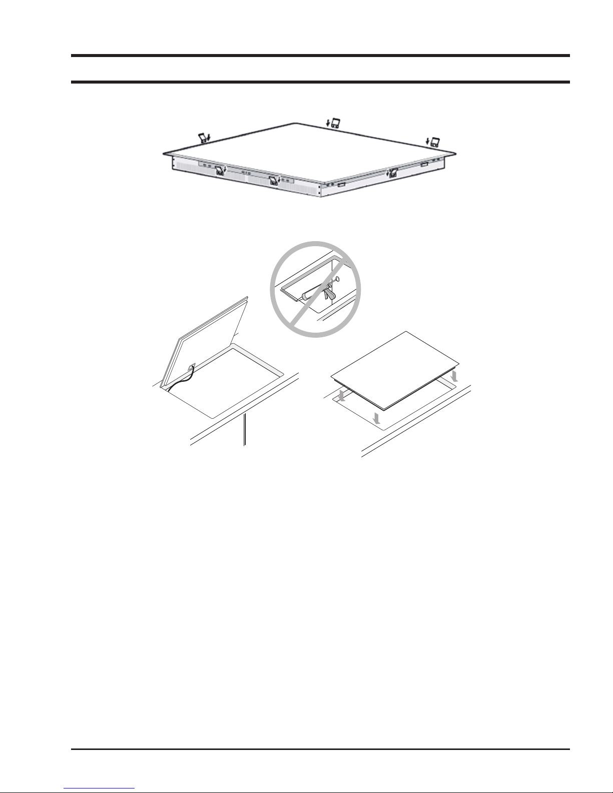
2-5 Installing the hob
This document can not be used without Samsung’s authorization.
- 7 -
This document can not be used without Samsung’s authorization.
3. Disassembly and Reassembly
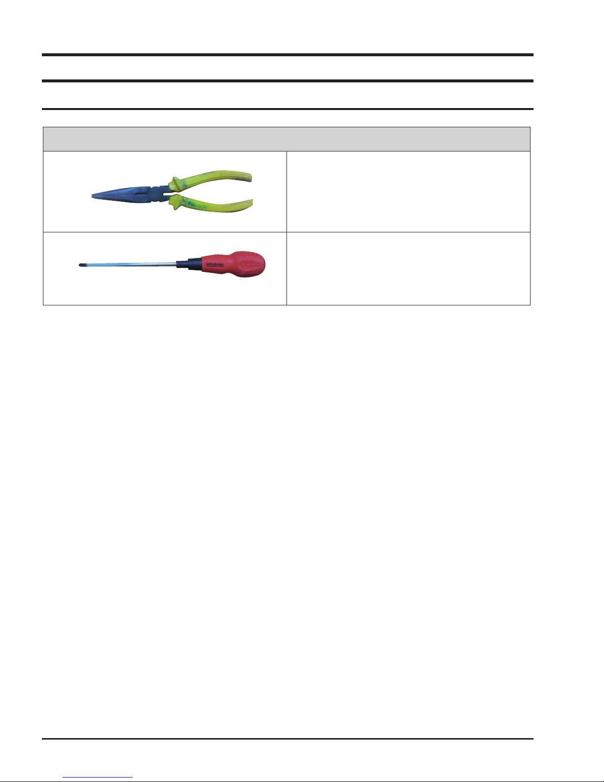
3-1 Tools for Removal and Reassembly
Tool
1. Tool : Longnose
2. Remarks : PBA hook
1. Tool : Driver
2. Type : ( + )
3. Remarks : SCREW
- 8 -
This document can not be used without Samsung’s authorization.
3-2 Replacement of the Assy Top Plate
Attention
The Ceramic Glass may break if you use force especially on the edge.
Parts Explanation Photo Explanation
Assy Top Plate
(Ceramic Glass)
1. Disconnect power.
2. Remove 4 - side direction 16 Screws
securing the Assy Top Plate to the Assy
Case Burner.
3. Raise the Assy Top Plate.
4. After replacement of the Assy Top Plate,
Screw the Assy Top Plate to the Assy Case
Burner.
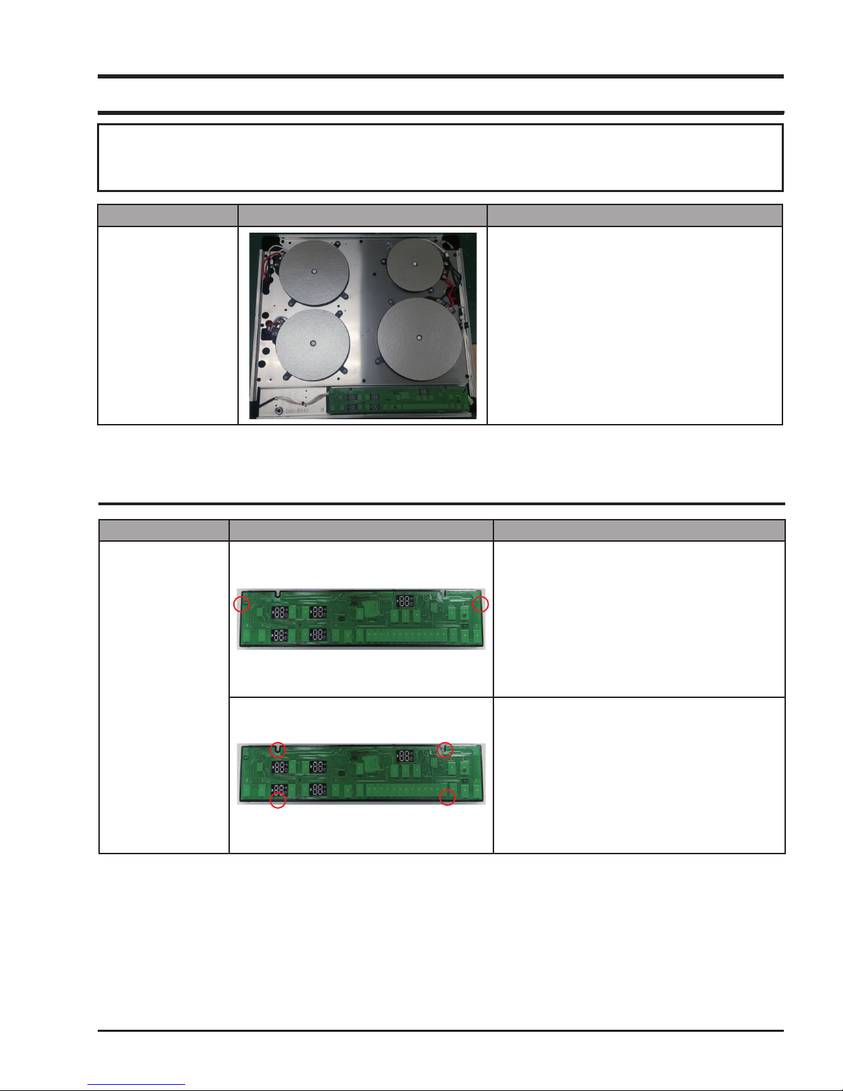
3-3 Replacement of the Assy Control Panel
Parts
Assy Control Panel
Explanation Photo
Explanation
1. Lift up the Control Panel Assy.
2. Disconnect all connectors.
3. Control PBA is xed by double-faced tape.
Separate Control PBA from Support PCB.
- 9 -
This document can not be used without Samsung’s authorization.
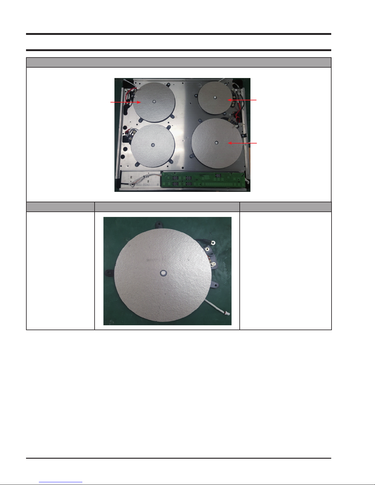
3-4 Replacement of the Working Coil
Explanation Photo
COIL WORKING FLEX
Parts Explanation Photo Explanation
Working Coil
COIL WORKING 145
COIL WORKING 210
1. Bend the Cover-Coil a little.
- 10 -

This document can not be used without Samsung’s authorization.
3-4 Replacement of the Working Coil
Parts Explanation Photo Explanation
2. Remove Screws securing the
Working-Coil
3. Disconnect all lead wires from the
Assy-Working Coil.
Working Coil
pull & rotate
4. For the replacement of Sensor-Top,
pull the Sensor-Top toward bottom
side.
5. Rotate the Sensor-Wire by
90degree until the Sensor-Top can
be remove from the Coil-Working.
- 11 -

This document can not be used without Samsung’s authorization.
3-5 Replacement of the PBA
Parts Explanation Photo Explanation
1. Remove all screws securing the
CASE-INDUCTION.
2. Disconnect all wires from the
WORKING-COIL.
PBA
3. Remove the CASE-INDUCTION.
4. Disconnect all wires from the
PBA.
- 12 -

This document can not be used without Samsung’s authorization.
3-5 Replacement of the PBA
Parts Explanation Photo Explanation
PBA
5. Remove all screws securing the
PBA.
6. The PBA is xed in place by a
series of hooks.
Remove these using a tool
Then remove the PBA.
- 13 -

This document can not be used without Samsung’s authorization.
01
02
03
04 06
05
L N
1N~ (32A)
01
220-240 V ~
04
Blue
02
Brown
05
Gray
03
Black
06
Green/Yellow
01
02
03
04
05
07
06
L1 L2 N
2N~ (16A): Separate the 2-phase wires
(L1 and L2) before connection.
01
220-240 V ~
05
Blue
02
380-415 V ~
06
Gray
03
Brown
07
Green/Yellow
04
Black
01 04
02
03
05
06
07
L1 N1 L1 N2
2 x 1N~ (16A): Separate the wires before
connection.
01
220-240 V ~
05
Black
02
Brown
06
Gray
03
Blue
07
Green/Yellow
04
220-240 V ~
3-6 Replacement of the POWER CABLE
Parts Explanation Photo Explanation
1. Remove screws securing the GND
WIRE and HOLDER-CABLE.
2. Remove locking holder.
Power Cable
3. Pull the POWER CABLE outwards
to remove it from the socket.
4. After nishing service, connect the
power cable properly to main power
supply.
- 14 -

This document can not be used without Samsung’s authorization.
4. Troubleshooting
4-1 Part Checking method
Parts Photo Good No Good
SENSOR TEMP
(DG32-00015A)
20˚C : 292.9kΩ
40˚C : 118.7kΩ
60˚C : 52.76kΩ
80˚C : 25.38kΩ
The others
IGBT Sensor
(DE95-00001A)
Coil-Working
20˚C : 57.9KΩ ~ 65.5KΩ
25˚C : 46.4KΩ ~ 52.2KΩ
30˚C : 37.5KΩ ~ 41.9KΩ
0.01~1Ω 100MΩ exceed
The others
- 15 -

This document can not be used without Samsung’s authorization.
4-2 DEMO mode
This mode is for Shop display.
At this mode, user can only operate touch key button without burner power on.
1. Touch Lock key for 3 seconds.
2. Touch Timer key for 3 seconds. An acoustic signal will sound.
3. Touch Pause key for 3 seconds within 10 seconds. An acoustic signal will sound.
4. Demo mode will be activated.
5. To exit the Demo mode, repeat No.1 ~ 3 procedure.
- 16 -

This document can not be used without Samsung’s authorization.
4-3 Failure Codes
4-3-1 Temp Sensor Information
Information
Code
Top Sensor Open Information (Sensor-Top)
It occurs due to a defective sensor, misplaced wires, a defective PCB and
when A/D value that MICOM senses rises over 252.
Also, it may occur when the ambient temperature falls under -10˚C.
Top Sensor Short Information (Sensor-Top)
It occurs due to a defective sensor, misplaced wires, a defective PCB and
when A/D value that MICOM senses falls under 10.
IGBT Sensor Open Information (Assy-Inverter Module)
It occurs due to a defective sensor, misplaced wires, a defective PCB and
when A/D value that MICOM senses rises over 239.
Also, it may occur when the ambient temperature falls under -10˚C.
IGBT Sensor Short Information (Assy-Inverter Module)
It occurs due to a defective sensor, misplaced wires, a defective PCB and
when A/D value that MICOM senses falls under 10.
Solution Page
18 Page
19 Page
20 Page
21 Page
4-3-2 Safety Information
Information Code Gerneral Function Solution Page
Touch Button Short
Information
Touch key data
Information
Over Temperature
Information
Pan Detection
Information
DC Motor Locking
Information
It occurs when the control panel’s sensor eld is shorted
for more than 8 seconds.
ex: No.1 Place a damp cloth on the control panel.
No.2 Liquid boils over and lands on the control panel.
No.3 More than one key is pressed for more than
8 seconds.
No.4 Defective Assy-Touch PCB
It occurs when the Touch key data at Display PCB is interrupted, due to some noise, defects of Display PCB.
It occurs when the temperature of the Top Sensor rises
very highly.
(Estimated temperature of ceramic glass’s surface is
more than 250˚C.)
ex: Place a empty cookware on the burner and operate the
hob.
It occurs when the cookware is unsuitable or too small or
no cookware has been placed on the cooking zone.
If the suitable cookware is placed again, the hob will operate normally.
It occurs when the DC Motor cannot operate due to defects
of PCB, wiring or some disturbance on motor blade.
Page
Page
Page
Page
Page
22
23
24
25
26
Communications
between main
It occurs when the Main PCB and sub PCB not
communication.
- 17 -
27
Page

4-3-3
This document can not be used without Samsung’s authorization.
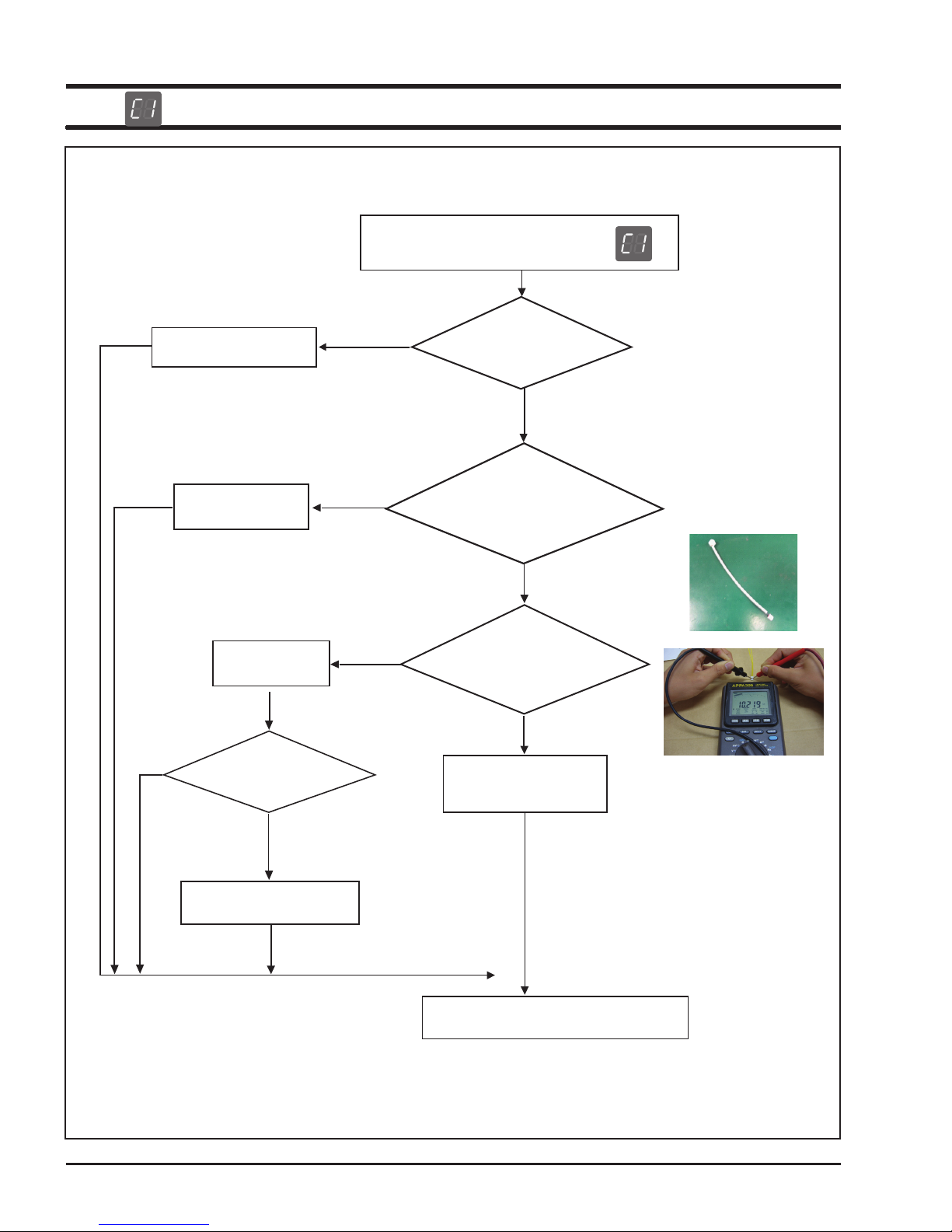
Connect the sensor.
Replace the wire.
Connect the wire
properly.
S/W Information
NO
After Power -> On, does
the symptom continue?
Top Sensor Open Information ( )
NO
NO
NO
Is the sensor connected?
Is the sensor wire
connected properly
by burner position?
Is the sensor's real
resistance a opened
The sensor has defect.
Replace the sensor.
circuit?
YES
: check if the sensor wire is damaged,
if the sensor housing is inserted into
the connector of the PCB.
YES
YES
YES
Replace the Assy Touch PCB.
Perform the operation again and check
if it is working properly.
- 18 -

4-3-4
This document can not be used without Samsung’s authorization.
Remove any foreign substance
from the shorted part.
S/W Information
NO
After Power -> On, does
the symptom continue?
YES
Top Sensor Short Information ( )
YES
NO
Is the sensor terminal part
of the PCB shorted?
real resistance a
The sensor has defect.
Replace the sensor.
No
Is the sensor's
shorted circuit?
YES
: check if the sensor is slightly shorted.
Replace the Assy Touch PCB.
Perform the operation again and check
if it is working properly.
- 19 -

4-3-5
connector of the PCB.
This document can not be used without Samsung’s authorization.
IGBT Sensor Open Information( )
Connect the sub wire.
Replace the sub wire.
S/W Information
NO
After Power -> On, does
the symptom continue?
NO
(from Assy-Inverter Module to
NO
NO
Is the sub wire connected?
Assy Touch PCB)
YES
Is the sub wire sequence matched
with PCB schematic?
YES
Is the sensor's real resistance a
opened circuit?
YES
The sensor has defect.
Replace the Assy-Inverter Module PCB.
: check if the sub wire is damaged
if the housing is inserted into the
YES
Replace the
Assy-Inverter Module PCB.
Perform the operation again and check
if it is working properly.
- 20 -

4-3-6
connector of the PCB.
This document can not be used without Samsung’s authorization.
IGBT Sensor Short Information ( )
Connect the sub wire.
Replace the sub wire.
S/W Information
NO
After Power -> On, does
the symptom continue?
NO
NO
NO
Is the sub wire connected?
(from Assy-Inverter Module to
Assy Touch PCB)
YES
Is the sub wire sequence matched
with PCB schematic?
YES
Is the sensor's real resistance a
shorted circuit?
YES
The sensor has defect.
Replace the Assy-Inverter Module PCB.
: check if the sub wire is damaged
if the housing is inserted into the
YES
Replace the
Assy-Inverter Module PCB.
Perform the operation again and check
if it is working properly.
- 21 -

4-3-7
This document can not be used without Samsung’s authorization.
Key Short Information ( )
Assy Touch PCB is
defective
Replace the
Assy Touch PCB
YES
YES
YES
Is the key not recognized
Is the key not recognized
after cleaning the control panel?
NO
does the symptom continue?
at all?
Is the key recognized
intermittently?
S/W Information
After Power > On,
NO
NO
NO
YES
Replace the sub wire
or Assy Touch PCB.
Perform the operation again and check if it
is working properly.
- 22 -

4-3-8
This document can not be used without Samsung’s authorization.
Touch key data Information ( )
After connect plug,
does the symptom continue?
YES
Replace the Touch PCB.
Perform the operation again and check
NO
Touch PCB is interrupted
due to some electrical noise.
if it is working properly.
- 23 -
4-3-9
This document can not be used without Samsung’s authorization.
Over Temperature Information ( )
Make the hob be cool
(Ceramic glass's surface)
Connect the wire
properly.
S/W Information
NO
After Power -> On, does
the symptom continue?
NO
YES
NO
Is the hob operated with
empty cookware?
NO
Is the Top sensor wire
connected properly by burner position?
YES
Is the Top sensor's real
resistance a
opened circuit?
YES
The Top sensor has defect.
Replace the sensor.
YES
Replace the Assy Touch PCB.
Perform the operation again and check
if it is working properly.
- 24 -

4-3-10
This document can not be used without Samsung’s authorization.
Pan Detection Information ( )
Place the cookware
Place the suitable
cookware
YES
YES
NO
Is the hob operated with
no cookware?
NO
Is the hob operated with
un-suitable cookware?
(small size, aluminium, etc)
NO
S/W Information
After Power -> On, does
the symptom continue?
YES
Replace the Assy-Inverter Module
or Assy Touch PCB,or Check the PCB Wiring.
Perform the operation again and check
if it is working properly.
- 25 -

4-3-11
This document can not be used without Samsung’s authorization.
DC Motor Locking Information ( )
Connect the Motor wire.
Remove the
interference at Motor.
YES
NO
Is the Motor wire connected?
YES
Is there some interference at rotor
or blade of Motor?
NO
S/W Information
NO
After Power -> On, does
the symptom continue?
YES
Replace the Inverter PCB,
Touch PCB or DC Motor.
Perform the operation again and check
if it is working properly.
- 26 -

4-3-12
This document can not be used without Samsung’s authorization.
Commnunication information ( )
Is the wire connected properly?
YES
Is the Main PCB or Sub PCB
S/W check properly?
YES
Replace the Main PCB and Sub PCB
YES
Perform the operation again and check
NO
NO
if it is working properly.
Connect wire propely
Update to S/W
YES
- 27 -

4-4 Electrical Malfunction
Troubleshooting (Power)
Check terminal block voltage.
(220V~240V, 50/60Hz)
YES
YES
YES
NO
No Power
Check the wiring.
NO
Check the votage of PCB, SMPS
-input : 220V~240V
-output : 12V, 5V
Replace the defected PCB.
Check the terminal block connections
Check the circuit breaker.
Replace or Repair the wiring
Troubleshooting (Heating)
Check the relay terminal voltage
(220V~240V)
NO
YES
YES
NO
Heating Failure
Check the wiring.
NO
Check the all IGBT terminal resistance
(G-E, G-C, E-C)
Is there any shorted circuit?
Perform the 'PCB failure' process
Repair the relay or missing circuit
component.
Replace or Repair the wiring
Check Fuse at Filter PCB.
Normally, If IGBT is damaged
and shorted, Fuse will blow and
power off.
YES
1. Replace the Fuse at Filter PCB.
If not change Fuse, Repaired Inverter
PCB will damage again.
2. Replace the Inverter PCB.
This document can not be used without Samsung’s authorization.
- 28 -

This document can not be used without Samsung’s authorization.
4-4 Electrical Malfunction
Troubleshooting (PCB failure)
PCB Failure
- Check the input voltage of
PCB SMPS (input checkpoint : 220V~240V )
YES
- Check the output voltage of
PCB SMPS (Output checkpoint : 5V/12V )
YES
Do all relays operate?
YES
Check the Assy-Inverter Module & Assy Touch PCB’s
input voltage(5V,12V,GND)
NO
NO
- Check Terminal block
voltage(220V~240V).
Reset the circuit braker or
check main power.
NO
Repair the relay or replace
NO
Replace PCB
PCB.
NO
YES
Replace or Repair the wiring
Repair Faulty wiring
or PCB check
YES
Replace PCB
- 29 -

This document can not be used without Samsung’s authorization.
4-5 Auto Function Check Test
Induction Hob can do self check test.
If product have some problem, test program will be stopped and display the corresponding information code.
Auto Function Check
Touch the LOCK
key for 3 seconds
If have some problem,
test will be stopped and
display the information code
Touch the KEEP WARM
key for 3 seconds
Touch the PAUSE key
for 3 seconds
Auto check start
Refer to 18 page
Failure Codes
* Information cause is wiring mistake or PCB defects.
- 30 -

- 31 -
This document can not be used without Samsung’s authorization.
5. P.C.B Diagrams
5-1 P.C.B Diagrams : Touch (Control) PCB
( This Document can not be used without Samsung’s authorization )
No Parts Number Part Name Function and Role
1
CN1 Inverter PBA wire connector Communication with Inverter PBA
2 CN2 VF PBA wire connector Communication with VF PBA
3 BZ Buzzer Beep sound
4 IC1 Touch MICOM MICOM for Touch Key operation
5 CN3 Touch MICOM burning connector Touch MICOM burning port. Not conntected
6 IC2 Main MICOM Main MICOM
7 CN4 Main MICOM burning connector Main MICOM burning port. Not conntected
8 IC3 Touch MICOM MICOM for Touch Key operation
9 CN5 Inverter PBA wire connector Communication with Inverter PBA
10 CN6 Relay PBA wire connector Communication with Relay PBA
11 CN7 Touch MICOM burning connector Touch MICOM burning port. Not conntected
2
1
3
4
5
6
7
8
9
10
11

- 32 -
This document can not be used without Samsung’s authorization.
5. P.C.B Diagrams
5-2 P.C.B Diagrams : SMPS PCB
( This Document can not be used without Samsung’s authorization )
No. Parts Number Part Name Function and Role
1 CON01 AC Input connector AC Voltage input of SMPS PCB
2 CON02 DC Output connector DC 12V, 5V supply to other PCB
1
2

- 33 -
This document can not be used without Samsung’s authorization.
5. P.C.B Diagrams
5-3 P.C.B Diagrams : Inverter PCB
( This Document can not be used without Samsung’s authorization )
No Parts Number Part Name Function and Role
1
BD1 Bridge Diode IC Bridge Diode IC
2 Q1 IGBT IC High freguency switching IC
3 CN1 Inverter MICOM burning connector Inverter MICOM burning port. Not conntected
4 CN2 Top-sensor wire connector Connect Top-sensor wire
5 CN3 Control PBA wire connector Communication with Control PBA
4
4
2 2
3
5
1

- 35 -
This document can not be used without Samsung’s authorization.
6. Wiring Diagrams
( This Document can not be used without Samsung’s authorization )

GSPN (GLOBAL SERVICE PARTNER NETWORK)
Area Web Site
Europe, CIS, Mideast & Africa gspn1.samsungcsportal.com
Asia gspn2.samsungcsportal.com
North & Latin America gspn3.samsungcsportal.com
China china.samsungportal.com
This Service Manual is a property of Samsung Electronics Co.,Ltd.
Any unauthorized use of Manual can be punished under applicable
International and/or domestic law.
© Samsung Electronics Co., Ltd. March.
2016 Printed in Korea
 Loading...