

Page 1

CS-250 Series
CHAIR SCALE
SERVICE MANUAL (v1.06D)
Page 2

CS-250 Series Chair Scales Service Manual
- 1 -
CONTENTS
1. PRECAUTIONS……………………………………………………………..2
2. INTRODUCTION……………………………………………………………3
3. SPECIFICATIONS……………………………………………………….....4
3.1Specifications………………………………………………………………...4
3.2 Load Cell Specification...............................................................…...5
4. INSTALLATION……….…………………………………………………….6
5. DESCRIPTION……….....................................................................8
6. OPERATION………………………………………………………………..10
1. Power ON/OFF…………………………………………………………10
2. Zero……………………………………………………………………...10
3. Tare……………………………………………………………………...10
4. Hold function…………………………………………………………....10
5. BMI function…………………………………………………………….11
6. Unit change…………………………………………………………….11
7. PARAMETER……………………………………………………………….12
8. CALIBRATION……………………………………………………………..1 4
9. BATTERY OPERATION…………………………………………………..15
10. RS-232 OUTPUT………………………………………………………………17
11. MAINTENANCE……………………………………………………………18
11.1 General………………………………………………………………..18
11.2 Error codes……………………………………………………………19
11.3 Determine the Problem……………………………………………...19
11.4 Testing Load Cell………………………………………………………19
11.5 Check PCB Voltages………………………………………………...21
11.6 Trouble Shooting……………………………………………………..21
Page 3
CS-250 Series Chair Scales Service Manual
- 2 -
WARNING
DISCONNECT ALL POWER TO THIS UNIT
BEFORE INSTALLING, CLEANING, OR
SERVICING. FAILURE TO DO SO COULD
RESULT IN BODILY HARM OR DAMAGE THE
UNIT.
CAUTION
Permit only qualified persons to service the instrument
Before connecting or disconnecting any components, remove the
power.
Failure to observe these precautions bodily harm or damage to or
destruction of the equipment.
1. PRECAUTIONS
The chair scale is a precision electronic instrument, handle it
carefully.
Do not install the scale in direct sunlight.
Verify the local voltage and receptacle type are correct for
the scale.
Only use original adaptor, other could cause damage to the
scale.
Pluggable equipment must be installed near an easily
accessible socket outlet.
Avoid unstable power sources. Do not use near large users
of electricity such as welding equipment or large motors.
Avoid sudden temperature changes, vibration, wind and
water.
Avoid heavy RF noise.
Keep the scale clean
Page 4

CS-250 Series Chair Scales Service Manual
- 3 -
2. INTRODUCTION
The CS-250 series chair scales, that amplifies signals from a load cell,
converts it to digital data and displays it as a mass value.
It is accurate, fast and versatile series of general purpose balances with %
weighing functions and accumulation.
Ergonomically optimized seat, comfortable, safe and reliable.
Grasp the handrails in two ways: gross grip area, vertical grip area.
Handrails with rubber material, comfortable and safe.
Adjustable angle of instruments to meet the user reading.
4 transportation wheels with brake.
Footrest foldable, when folded out with low distance to the floor.
Each single armrest foldable.
Bag for power supply fixed on the chair, when power supply not in use.
Optional RS-232 interface, can connect computer and printer.
Page 5
CS-250 Series Chair Scales Service Manual
- 4 -
Model
CS-250
Maximum Capacity
250kg
Readability
100g
Resolution
1/2,500
Tare range
-249.9kg
Minimum Capacity
2000g
Linearity ±
200g
Common Specifications
Interface
RS-232 Output Optional
Stabilisation Time
2 Seconds typical
Operating Temperature
0°C - 40°C / 32°F - 104°F
Power supply (external)
12V/500mA AC power adapter
Calibration
Automatic External
ADC
Σ-Δ
Display
25 mm high 6 digits LCD with auto backlight and
loading bar graph
Housing
Aluminium platform, ABS plastic indicator
Gross weight
19kg
3. SPECIFICATION
3.1 Specifications
Page 6
CS-250 Series Chair Scales Service Manual
- 5 -
Model No
L6D
Rated Capacity (kg)
2.5/3/5/6/8/10/15/20/30/35/40/50
Sensitivity
2.0±0.2 mv/v
Excitation Voltage
5~12V
Material
Aluminum
Cable
0.3~3m Φ 4mm
Input Resistance
409Ω ±6Ω/1065Ω ±15Ω
Out put Resistance
350Ω ±3Ω/1000Ω ±10Ω
Temperature Range
-35°C ~ +65°C
Safe overload
150%F.S
Ultimate overload
300%F.S
Error
±0.0233%F.S
Creep (20min)
±0.020%F.S
Zero Balance
0±5%mV/V
Max. Platform Size
250x350mm
3.2 Load Cell Specifications
Page 7
CS-250 Series Chair Scales Service Manual
- 6 -
4. INSTALLATION
Unpacking
Carefully take the balance out of its package, make it sure its not damaged and
all accessories are included.
Remove the weighing scale from the carton.
Remove the protective covering. Store the packaging and to use if you
need to transport the scale later.
Inspect the scale and terminal for damage.
Make sure all components are included
Accessories,
1. Balance
2. Adaptor
3. Product manual
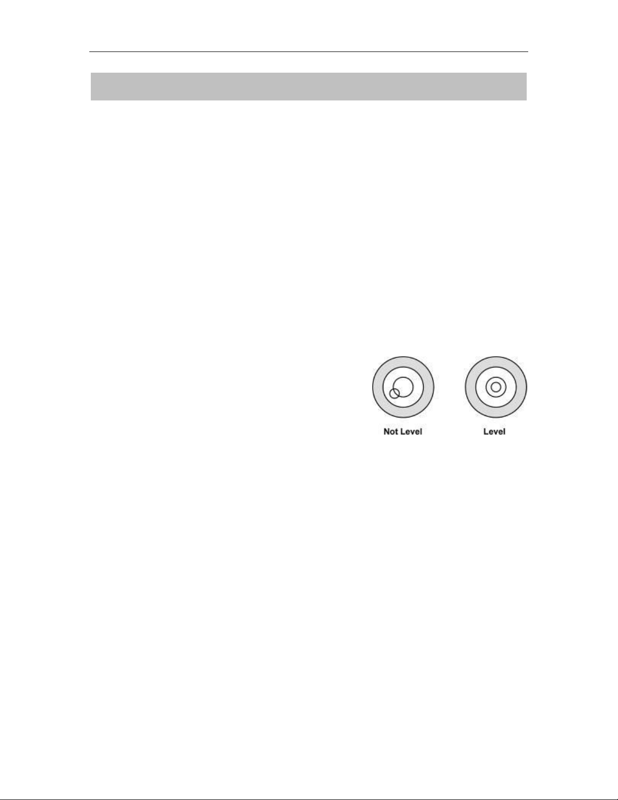
Level Adjusting
Place the scale on a table.
Check the water mark. If, bubble is not centre
adjust the leveling feet until reach centre. Check
the level when you change the location.
Charging Battery
To charge the battery insert the adaptor pin to jack, jack is locating rear side
of the scale. Adaptor simply plug into the mains power. The scale no
needs to be turned on.
The battery should be charged for 12 hours for full capacity.
In the display there is an indicator show the status of battery charging.
When the scale is plugged into the mains power the internal battery will be
recharged. If the indicator off, the battery has a full charge. If it is on, the
battery is nearly discharged and if yellow, the battery is being charged.
Do not use any other type of power adaptor than the one supplied with the
scale.
Verify that the AC power socket outlet is properly protected.
Note: Please charge the battery before using the scale for the first time
Page 8
CS-250 Series Chair Scales Service Manual
- 7 -
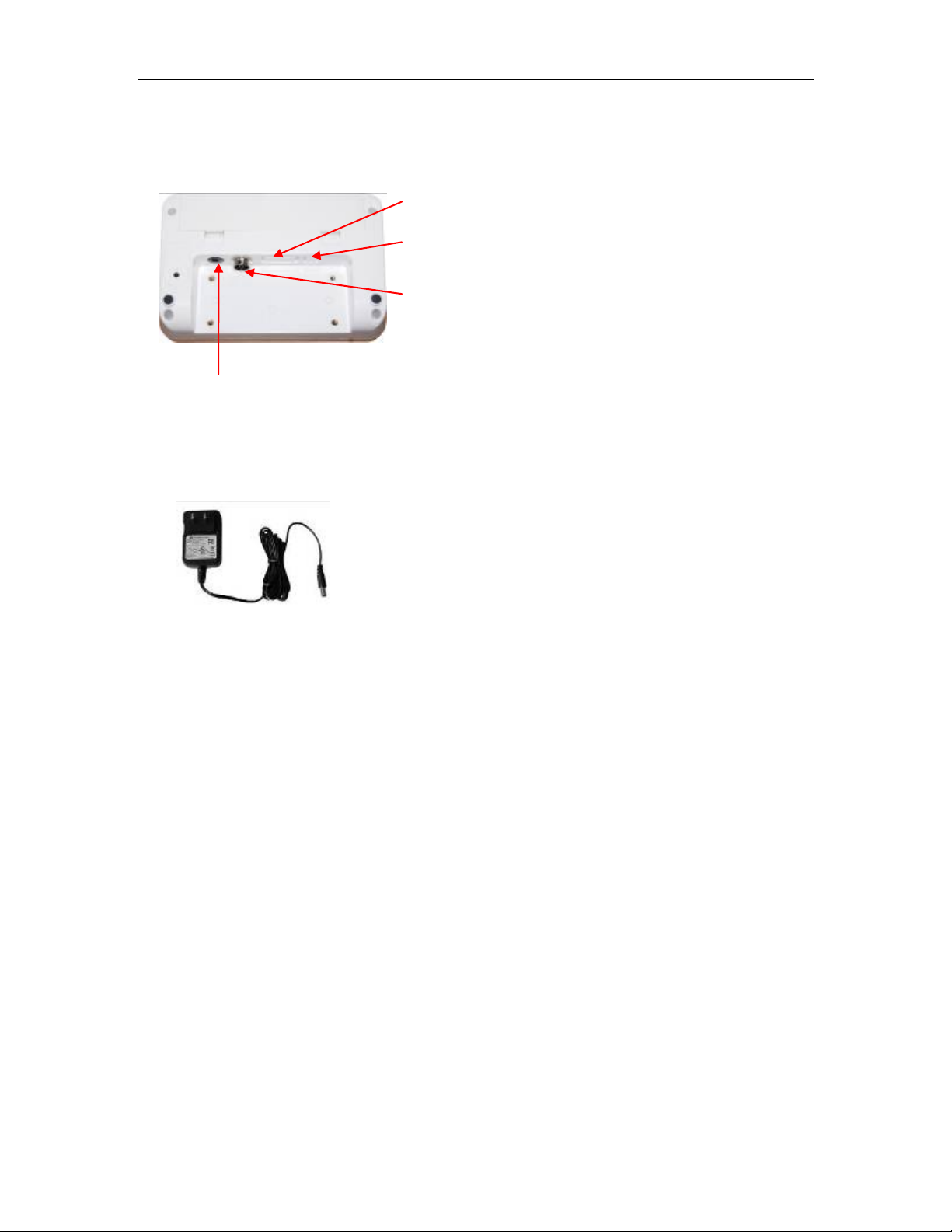
Installation
RS-232 Connecter
USB Connecter
Load cell Connecter
Adaptor Jack
Place the scale on a table.
Connect the adaptor pin in to the scale adaptor jack. Adaptor jack is
locating, rear side of the scale.
Adaptor connects into your AC power socket.
Pluggable equipment must be installed near
an easily accessible socket outlet with a
protective ground/ earth contact.
Turn on the On/Off key. If you want to turn off,
press the key again.
Display will be show the version number and will be starting self checking.
After self checking, display will be come to normal weighing mode.
Warm-up time of 15 minutes stabilizes the measured values after
switching on.
Calibrate with exact calibration weights, minimum 1/3 of the scale capacity
want to use for calibration. For calibration see details in parameter.
Then you can start your operation
Page 9

CS-250 Series Chair Scales Service Manual
- 8 -
Turns the scale power On / Off
Set to hold mode
Set to BMI mode
Enter into the menu
Sets display to Zero
Subtracts weight of container
Set weight unit
5. DESCRIPTION
Key Board
Page 10

- 9 -
Display
DISPLAY
FUNCTION
STABLE
Indicator for Display stability
ZERO
Indicator for Zero display
TARE
Indicator for Tare display
NET
Indicator for Net weight
GROSS
Indicator for Gross weight
BMI
Indicator for BMI operations
Indicator for BMI graph
Cm/inch
Indicator for measuring units
Lb/kg
Indicator for weight units
Indicator for Charging status of battery
Voltage has dropped
Low Voltage
Fully Charged
CS-250 Series Chair Scales Service Manual
Page 11

CS-250 Series Chair Scales Service Manual
- 10 -
6. OPERATION
Initial Start-up
Warm-up time of 15 minutes stabilizes the measured values after switching on.
6.1 Power ON/OFF
Switch on the scale by pressing . The display is switched on and the
self test is started.
If you want to switch off press the key again.
6.2 Zero
Environmental conditions can lead to the balance exactly zero in spite
of the pan not taking any strain. However, you can set the display of
your balance to zero any time by pressing key and therefore
ensure that the weighing starts at zero.
6.3 Tare
The weight of any container can be tared by pressing key so that with
subsequent weighing the net weight of the object being weighed is always
displayed.
Load weight on the pan.
Press key. Zero is displayed, and tare is subtracted.
Remove weight from the platform. Tared weight is displayed. It can
set only one tare value. It can display with a minus value.
Press key. Zero is displayed, tare weight is cleared.
6.4 Hold function
The weight(>20d) of any container can be hold by pressing key, the weight
value will be hold on the display, press key again will turn back to normal
weighing mode.
Page 12

CS-250 Series Chair Scales Service Manual
- 11 -
6.5 BMI function
Press key on the weighing mode, display will show the last setting of the
height value “xxxxxx”, and “BMI” indicator will turned on
Press key to select the height to cm / inch
If necessary, use and keys to setting new height value, then press
key confirm.
Display will be show the BMI graphics bar and weighing value.
Press key will turn back to weighing mode, BMI” indicator will be turned off.
6.6 Unit change
Press key to select the weight unit (kg/lb).
When in BMI settings, it can select to cm/ inch.
Page 13

CS-250 Series Chair Scales Service Manual
- 12 -
Menu
Sub
Menu
Description
F1 off
Off 0
To set to turn off scale automatically, as per
selecting time, when scale not in use.
Off 3
Off 5
off15
Off 30
P cont
Send data continuous
SEirE
Set the remote display
ask
ASK mode
Command R: read data
Command T: Tare
Command Z: Zero
F1 off
7. PARAMETERS
Enter the Menu
In the normal weighing mode, press key
Display will be show
Choose the Menu / Sub Menu
Press , it can choose menu block or options one by one.
Enter the Selected Menu
Press , it can confirm which will be shown displayed.
Enter in to TECH
When display showed Pi n , press and keys to enter the
function
Escape from the Menu
Press key, it can escape from the menu to weighing mode.
Parameter Block
Page 14

CS-250 Series Chair Scales Service Manual
- 13 -
F2 COM
P cnt2
Another mode, to send data continuous,
P STAB
Send data when the display stable
F3 bk
Bl on
Set the backlight always on.
Bl off
Set the backlight always off.
Bl au
Set the backlight automatic on.
F4 str
Str on
Multi tare operation turn on
Str of
Multi tare operation turn off
tch
pin
Press password to enter into the technical
parameter
P1 spd
Spd 7.5
To select display AD speed,
Spd 15
Spd 30
Spd 60
P2 cal
Cur ut
kg
Select to current weighing unit “kg”
Cur ut lb
Select to current weighing unit “lb”
Cal ut
kg
Select to calibration unit “kg”
Cal ut lb
Select to calibration unit “lb”
desc
To select scale decimal points;
Options: C 0, C 0.0, C 0.00, C0.000
C0.0000
Inc
To select scale division/increment;
Options: Div 1, Div 2, Div 5, Div 10,
Div 20, Div 50
Cap
Select to set scale capacity
Cal
Scale Calibration; details check the calibration
section
tri
To modify the calibration.
This display will be show XXXXX. For trimming
the load cells, showing primary weight.
You can calculate new rate by this formula:
N2=N1+N1×[(K2-K1)÷K2]
N1: primary rate, N2: new rate, K1: calibrate
weight, K2: display weight
count
To show the scale internal count
reset
Reset the scale
setgra
Set the local gravity value
Note: When Jumper K2 is connected on the PCB, then only can access
“tch” parameters.
Page 15

CS-250 Series Chair Scales Service Manual
- 14 -
unload
0100..00lb
load
pass
F1 off
tch
pin
P1 spd
P2 cal
Cur utlb
Cal utlb
desc
8. CALIBRATION
Simple Calibration;
Turn on the scale.
Press key during normal weighing, display will be show
Press key to confirm display will be show last calibrated test weight
value.
If necessary, use and keys to change new test weight value,
then press key confirm
Display will be show
Place the test weight on the chair.
After stable, press key confirm
Display will be show
Then will start self-test and will come to normal display.
Calibration Settings in the Parameter;
Turn on the scale. And when in the normal display
Press key, display will be show
Press key until to display
Press key to confirm display will be show
Press and keys, display will be show
Press key to show display
Press key to enter calibration. Display will show
Press key to choose the weighing unit(kg/lb) for to select unit of
current operation, press key to confirm.
Display will show
Press key to choose the calibration unit(kg/lb) for to select unit of
calibration, press key to confirm
Display will show
Page 16

CS-250 Series Chair Scales Service Manual
- 15 -
Cal
0100..00lb
load
pass
Press key until display show
display will be show
Press key to confirm display will be show last calibrated test weight
value.
If necessary, use and keys to change new test weight value,
then press key confirm
Display will be show
Place the test weight on the chair.
After stable, press key confirm
Display will be show
Then will start self-test and will come to normal display
Page 17

CS-250 Series Chair Scales Service Manual
- 16 -
9. BATTERY OPERATION
The Medical Scales can be operated from the battery if desired. The battery life
is approximately 40 hours.
When the battery needs charging a symbol on the weight display will turn on. The
battery should be charged when the symbol is on. The scale will still operate for
about several minutes after which it will automatically switch off to protect the
battery.
To charge the battery simply plug into the mains power. The scale does not need
to be turned on.
The battery should be charged for 12 hours for full capacity.
Just under the quantity display is an LED to indicate the status of battery
charging. When the scale is plugged into the mains power the internal battery
will be charged. If the LED is green the battery has a full charge. If the LED is
green the battery has a full charge. If it is blue indicates the battery is being
charged.
As the battery is used it may fail to hold a full charge. If the battery life becomes
unacceptable then contact your distributor.
Note: Useless battery should be want to use for recycle.
Page 18

CS-250 Series Chair Scales Service Manual
- 17 -
Pin 2
RXD
Input
Receiving data
Pin 3
TXD
Output
Transmission data
Pin 5
GND ― Signal ground
10. RS-232 OUTPUT
The CS-250 Series of scales can be ordered with an optional RS-232 output.
Specifications:
RS-232 output of weighing data
ASCII code
600~9600 Baud
No Parity
RS-232 (9pin D type connector)
9pin D Connecter:
Scale Computer/Printer
Pin 2: Pin 3
Pin 3: Pin 2
Pin 5: Pin 5
Note: If data is not getting in PC/Printer, want to inter-change one of the Pin 2
and Pin3 connections
Page 19

CS-250 Series Chair Scales Service Manual
- 18 -
WARNING
DISCONNECT ALL POWER TO THIS UNIT
BEFORE INSTALLING, CLEANING, OR
SERVICING. FAILURE TO DO SO COULD
RESULT IN BODILY HARM OR DAMAGE THE
UNIT.
CAUTION
Permit only qualified persons to service the instrument
Before connecting or disconnecting any components, remove the
power.
Failure to observe these precautions bodily harm or damage to or
destruction of the equipment.
11. MAINTENENCE
11.1. General
If the scale does not operate properly, find out the problem as possible.
Determine whether the problem is constant or alternate. Be aware that problems
can be caused by mechanical or electrical influences.
Check the following.
Water
Corrosive materials
Vibrations or temperature or wind
Physical damage
Check the scale cables for damage, and check all connections and connecters
for any loose contact or incorrect connection
Page 20

CS-250 Series Chair Scales Service Manual
- 19 -
Error Code
Description
POSSIBLE CAUSES
Err 4
Zero range exceeded, due
to turning on or by pressing
Goods on the platform
Overload, when
zeroing the scale.
Improper calibration
Load cell problem
PCB problem
Err 6
A/D Count out of the range
Platform not installed
Load cell problem
PCB problem
Err 19
Auto zero out of limit
Remove the goods
from the chair and turn
on again.
Cleaning
Disconnect the power before cleaning.
Use a cloth with mild suds and light cleaning agents.
Make sure that fluid not able to get into the device.
Use a clean and soft cloth for rub off.
11.2. Error Codes
11.3. Determine the Problem
Determine whether the problem is in the PCB or the Load Cell
Remove power from the system, and disconnect the load cell connection
from the PCB
Connect the PCB to a load cell simulator
Reapply power and test the PCB
If problem goes away, its source is probably in the Load cell. Check the
wiring, connecter, load cell and mechanical components of the load cell.
If problem persists, its source is probably in the PCB. Check the PCB voltages,
connecters, cables and function programs
11.4. Testing Load cell
For testing load cell, remove power from the system, and disconnect the PCB
from the Load cell
Physical Test:
Check the moisture, or foreign material inside.
Check load cell surface badly rusted or corroded
Page 21

CS-250 Series Chair Scales Service Manual
- 20 -
Measuring Points
Resistance
Red (+ Exc) to Black ( –Exc)
409 ±6Ω
Green (+Sig) to White ( –Sig)
350Ω ±3Ω
Check the strain gauge areas become compressed
Check any physical damage (body bent or twisted) to the load cell
Check load cell cable, all leads are connected, any cut, splits or tears.
Check load cell for proper input and output resistances
Electrical Test:
Use an accurate multimeter to check the ohms
Load Cell Connections
Signal + Green
Supply + Red
Signal - White
Supply - Black
Shield
Resistance
Leakage Resistance
Check each of the load cell wires to the load cell cable screen.
Check each of the load cell wires to the load cell body.
These readings should be greater than 1000mΩ or OL.
If this reading is less than 1000 mΩ, then this load cell has leakage between
the internal circuit and the load cell body or cable screen
Zero Balance
Connect the load cell to a stable DC source of between 5 to 10V
Connect multimeter to mV and connect to the load cell signal wires
The meter should read 0.00mV ± approximately 1 % of full load.
If the output reads greater than ±10% of full scale capacity, then the load cell
will require replacement.
Page 22

CS-250 Series Chair Scales Service Manual
- 21 -
Problems
Possible cause
Common Solutions
Display is blank.
No self test
Mains power is turned
off. Power supply faulty
or not plugged. Internal
battery is not charged.
On/Off switch problem
Check power is getting inside the
scale and on/off switch is working.
Verify the voltages, which is on the
power labels.
Blank display
after self test
Pan not installed.
Unstable weight, load
cell damaged
Check the pans are installed
correctly. Try to turning on again.
11.5. Check PCB Voltages
If the problem is in the PCB, use a multimeter to check the following voltages
11.5.1 AC Power
Check the AC power socket out put voltage.
Voltage must be a -20% and +10% of the normal AC voltage.
11.5.2 Adaptor Voltage
Check the adaptor output cable connecter voltage
Voltage must be minimum 9VDC and maximum 15VDC
11.5.3 PCB Input Voltage
Check the PCB input power connecter voltage
Voltage must be minimum 9VDC in to the pin AD+
11.5.4 Check Battery Voltage and Charging Voltage
1. Check the Battery Voltage,
Voltage must be minimum 6VDC. If below the 6VDC connect the adaptor
for charging
The battery voltage below the 5.5VDC, replace the battery and install new
6V/3.4Ah battery.
2. Check the Battery Charging Voltage;
Remove the battery connection terminals (Red and Black) from the battery.
Connect the power and turn on the scale
Voltage into the terminal minimum 6.5VDC
11.6 Trouble Shooting
Page 23

CS-250 Series Chair Scales Service Manual
- 22 -
OL or -------
Maximum capacity
exceeded. Load cell or
mechanics damaged.
Power supply faulty
Check the platform is installed
correctly. Try to turn on the scale
again. Do the calibration again
------- or NULL
displayed
Weight is on the
platform is below
permissible limit. Pan
not installed correctly.
Power supply faulty.
Load cell or
mechanism faulty
Check the platform is installed
correctly. Try to turn on the scale
again.
Do the calibration again
Display is
unstable
Goods touching
somewhere. Air
variation or any
vibrations.
Temperature
changed . Load cell or
connections faulty.
Power supply faulty
Check the scale is in acceptable
location.
Check the connecters and load cell.
Check the power supply and battery
Weight value
incorrect
Calibration error.
Platform of load cell
touching somewhere.
Wrong weighing unit
Use accurate weight for to do the
calibration
Check the pan and load cell is
installed proper and touching.
Check the parameter settings.
Check the load cell and connecters
Can not use full
capacity
Over load protection
stoppers or transport
locks are not removed.
Parameters are set
incorrectly.
AD problem.
Load cell or
mechanism damaged
Check the stoppers and locks under
the platform.
Check the weighing unit and
parameter settings.
Check the load cell.
Platform Corner
Weight different
Over load protection
stoppers or transport
locks are not removed.
Load cell or
mechanism damaged
Check the stoppers and locks under
the platform.
Use accurate weight for to do the
calibration
Check the load cell.
Battery not
charging
Mains voltage problem
Charging circuit
problem
Battery Problem
Check the mains and adaptor.
Check the battery.
Check the charging circuit
Page 24

Brecknell Weighing Products
1000 Armstrong Dr.
Fairmont, MN 56031
Toll free: 800-637-0529
Tel: 507-238-8702 Fax: 507-238-8271
e-mail: sales@brecknellscales.com
www.brecknellscales.com
 Loading...