


Model 6700 Family
Point-of-Sale Interface Scales
Model 6720
Model 6702
Model 6710
User’s Manual

CAUTION
Risk of electrical shock. Do not remove cover. No user serviceable parts inside. Refer servicing to qualified service personnel.
Avery Berkel reserves the right to change specifications at any time.
October 2009 6700_u_en_7424_14787.p65 Issue AJ Printed in USA
2 |
Model 6700 Family User’s Manual |

Table of Contents
Specifications ...................................................... |
4 |
Initial Setup ......................................................... |
7 |
Operation ............................................................ |
8 |
Menu Structure .................................................. |
11 |
Diagnostics Mode .............................................. |
13 |
Configuration Mode ........................................... |
17 |
Calibration Mode ............................................... |
19 |
Review/Test Scale Settings ............................... |
21 |
Communication ................................................. |
22 |
Error Codes ....................................................... |
23 |
Troubleshooting................................................. |
24 |
Spare Parts Listing ............................................ |
26 |
Model 6700 Family User’s Manual |
3 |

Specifications
Description
Capacity/Resolution
Agency Certificates
of Conformance
The Avery Berkel 6700 models are digital electronic bench scales specifically designed for point-of-sale applications and are “Legal-for- Trade.” The scales are easily interfaced with a cash register, computer or other POS terminal.
Important! Weights and Measures normally requires inspection of scale before scale is placed into operation.
Model |
Capacity (lb) |
Capacity (kg) |
6702-7 |
15 x .005 |
7 x .002 |
6702-15 |
30 x .01 |
15 x .005 |
6710-7 |
15 x .005 |
7 x .002 |
6710-15 |
30 x .01 |
15 x .005 |
6720-7 |
15 x .005 |
7 x .002 |
6720-15 |
30 x .01 |
15 x .005 |
6720-30 |
60 x .02 |
30 x .01 |
6720-60 |
120 x .05 |
60 x .02 |
Model 6702/6710/6720
US and Canada Approved Legal for Trade USA: NTEP COC# 95-070
Canada: MOI# AM-5076
4 |
Model 6700 Family User’s Manual |

Dimensions
Power Supply
Frequency
Power Requirements
Operating Temperature
Construction
Display
Scale Leveling
Zero Window
Model 6702: 10.4 x 6.4 x 2.5
Model 6710: 10.4 x 10.4 x 2.5
Model 6720: 14.1 x 12.6 x 4.1
UL/CSA approved power supply with 6’ line cord
6702/6710: Wallmount
6720: In-line mounted below scale
Input: 120 VAC +10%-15%, Standard 3 wire w/ground
Output: 15 VDC @.3 Amps DC
50/60 Hz selectable
0.1 amp maximum
42ºF – 104ºF (5ºC – 40ºC)
10% to 95% RH (non-condensing)
Models 6702/6710: Aluminum Base and Load Bridge with stainless steel weigh platter. Overload protection: Adjustable center and side stops.
Model 6720: Die cast aluminum base with a stainless steel weigh platter.
Overload protection: Adjustable center stop, fixed corner stops.
½" high, six-digit LCD.
Key panel with ZERO and TEST keys. Remote display with 7 ft. cable. Standard on Models 6702 and 6710, optional on 6720.
Using the leveling bubble as a guide, adjust the four adjustable feet to level the scale.
Initial automatic zero setting is ±10% of maximum capacity—active at power up. Manual zero setting range is ±2% of maximum capacity— active using the ZERO key.
Model 6700 Family User’s Manual |
5 |
Under Capacity Limits |
Under capacity indication will be given with |
|
dashes appearing on the bottom line of the |
|
display whenever the display is below the initial |
|
zero value. |
Over Capacity Limits |
Over capacity indication will be given with |
|
dashes appearing in the upper line of the |
|
display whenever the weighed item exceeds 9 |
|
divisions over the rated capacity of the unit. The |
|
scale will use the initial zero value for reference |
|
for over capacity determination. |
Sealing |
Access to the calibration switch can be secured |
|
with a lead wire or pressure sensitive security |
|
seal. The remote or primary indicators have no |
|
metrological features that require the use of a |
|
security seal. |
Internal Counts |
The scale has 100,000 internal counts. |
Dynamic Response |
The time interval when weight is applied to the |
|
scale until a stable weight is displayed: |
|
0–1000d,1.5 seconds |
|
1000d+, 2.0 seconds |
|
maximum mean average |
Communications |
Factory default settings: 9600 baud, 7 data bits, |
|
even parity, 1 stop bit. |
|
Specific cable requirements are determined by |
|
particular POS terminal. A standard 9-pin pass |
|
through RS-232 interface cable is necessary for |
|
most PC interfaces. Not a null modem. |
|
RS-232 bidirectional, configurable 1200 to |
|
19.2K baud. Transmits weight and scale status |
|
whenever ASCII “W” <CR> is sent by the POS |
|
terminal. Standard ECR protocol is OPOS |
|
compatible. For Protocol details contact factory. |
6 |
Model 6700 Family User’s Manual |

Initial Setup
Unpacking the Scale
Installing the Scale
Model 6702
Model 6710
Model 6720
1.Remove contents of the shipping container.
2.Inspect the scale for evidence of shipping damage. Immediately report any damage to the shipper.
1.Mount the scale on a stable, level surface that is free from air currents and vibration. Be sure the scale platter does not touch any adjacent surfaces.
2.To install the scale surface flush with a countertop, use the dimensions on the following page to guide construction.
Scale Dimensions |
Min. Cut-Out Dimensions |
|
D |
10.4 in. (26.4 cm) |
11.1 in. (28.2 cm) |
W |
6.4 in. (16.3 cm) |
7.1 in. (18.0 cm) |
H |
2.5 in. (6.35 cm)* |
|
*Adjustable to 3.0 in. (7.6 cm) |
||
Scale Dimensions |
Min. Cut-Out Dimensions |
|
D |
10.4 in. (26.4 cm) |
11.1 in. (28.2 cm) |
W |
10.4 in. (26.4 cm) |
11.1 in. (28.2 cm) |
H |
2.5 in. (6.35 cm)* |
|
*Adjustable to 3.0 in. (7.6 cm) |
||
Scale Dimensions |
Min. Cut-Out Dimensions |
|
D |
12.6 in. (32.0 cm) |
13.25 in. (33.7 cm) |
W |
14.1 in. (35.8 cm) |
14.75 in. (37.5 cm) |
H |
4.1 in. (10.4 cm)* |
|
*Adjustable to 4.6 in. (11.7 cm)
Model 6700 Family User’s Manual |
7 |

3.Loosen the collets or jam nuts on the leveling feet. Level the scale by using the level bubble under the scale platter as a guide. Be sure all four feet are in firm contact with the counter, then tighten all collets and jam nuts.
4.Make sure all power cords, remote display cables, etc., are not touching the live weighing surface.
5.Plug the unit into an appropriate voltage outlet that is properly grounded.
6.The 6720 scale can support more than one display; however, only one keypad is operable. Switch 3 selects internal or external display keypad operation.
Switch 3 Settings
Closed= internal display keys operational Open = external display keys operational
The normal setting for the 6720 with the internal display is Switch 3=Closed. On 6720 w/remote only or 6710 and 6702 scales, Switch 3=Open.
Operation
Power Up Test
Sequence
If RAM or ROM error is reported, you must press the TEST key to acknowledge the condition. See “Error Codes” section.
When the scale is first powered up, it will perform a test sequence. During this sequence, the display will show the following:
•The model number and the software version/revision level.
•A numeric counting test for all segments of the display. During this test, a test of Random Access Memory (RAM) and a test of Read Only Memory (ROM) is performed.
If everything is OK, the display will show zero weight and the scale is ready for use.
8 |
Model 6700 Family User’s Manual |
Performing a Normal
Weighment
If the scale is outside the ± 2% zero window, center dashes are displayed “- - - -.” If necessary, reapply power to reset the initial zero setting.
Operation Controls
Accessing the
Menu Mode
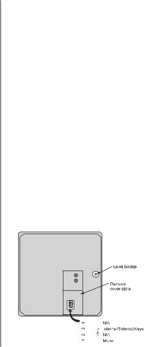
Figure 1
6720 Switch
Location
1.With the scale powered on, make sure the scale platter is empty and the display is at zero. If it is not, press the ZERO key…
0.00is displayed.
2.Place an item to be weighed on the scale platter…
The scale will display the gross weight.
3. Remove the item from the scale platter.
ZERO Key – The ZERO key will zero the scale if weight is stable, and acts as the NO or SCROLL key in the Menu mode.
TEST Key – The TEST key can be used to perform the initial power-up test sequence, recall diagnostic routines, or to view the scale configuration information. This key also acts as YES or ACCEPT in the Menu mode.
The 6700 models power up ready for weighing operations. Access the Menu mode by setting Switch 1 shown in Figure 1 or 2 to the OPEN or Menu mode position.
Top View of 6720 Scale with Platter Removed.
|
|
|
|
|
|
|
|
|
|
|
|
|
|
|
|
|
|
|
|
|
|
|
|
|
|
|
|
|
|
|
|
|
|
|
|
|
|
|
|
|
|
|
|
|
|
|
|
|
|
|
|
|
|
|
|
|
|
|
|
|
|
|
|
|
|
|
|
|
|
|
|
|
|
|
|
|
|
|
|
|
Model 6700 Family User’s Manual |
9 |
|||||||
 Loading...