


Model 200 Series
Operation & Set-up Manual
Revision 2.1
December, 2005
Contents subject to change without notice.
Salter Brecknell Weighing Products
1000 Armstrong Drive
Fairmont, MN 56031
Tel (800) 637-0529
Tel (507) 238-8702
Fax (507) 238-8271 E-mail: sales@salterbrecknell.com
Web: www.salterbrecknell.com.
NOTE
This equipment has been tested and found to comply with the limits for a Class A digital device, pursuant to Part 15 of the FCC Rules. These limits are designed to provide reasonable protection against harmful interference when the equipment is operated in a commercial environment. This equipment generates, uses and can radiate radio frequency energy and, if not installed and used in accordance with the instructions manual, may cause harmful interference to radio communications. Operation of this equipment in a residential area is likely to cause harmful interference in which case the user will be required to correct the interference at his/her own expense.
TABLE OF CONTENTS
|
|
Page |
Chapter 1: |
Introduction to the 200 Series Indicator ................................................................... |
1-1 |
Chapter 2: |
Installation ................................................................................................................... |
2-1 |
2.1 |
ABS Enclosure .............................................................................................................. |
2-1 |
|
2.1.1 Connecting the weigh platform......................................................................... |
2-1 |
|
2.1.2 Connecting the serial printer, remote display or computer .............................. |
2-2 |
|
2.1.3 Connecting the power supply........................................................................... |
2-2 |
2.2 |
Stainless Steel Enclosure ............................................................................................. |
2-3 |
|
2.2.1 Connecting the weigh platform......................................................................... |
2-4 |
|
2.2.2 Connecting the serial printer, remote display or computer .............................. |
2-4 |
|
2.2.3 Connecting the power supply........................................................................... |
2-4 |
Chapter 3: |
Configuration............................................................................................................... |
3-1 |
3.1 |
Configuration Overview................................................................................................. |
3-1 |
3.2 |
Setup (“F”) Menu ........................................................................................................... |
3-1 |
|
3.2.1 Entering the Setup Menu – ABS Enclosure ..................................................... |
3-1 |
|
3.2.2 Entering the Setup Menu – Stainless Steel Enclosure .................................... |
3-1 |
|
3.2.3 Navigating in the Setup Menu .......................................................................... |
3-2 |
|
3.2.4 Notes on the Setup Menu ................................................................................ |
3-3 |
|
3.2.5 Exiting the Setup Menu – ABS Enclosure........................................................ |
3-3 |
|
3.2.6 Exiting the Setup Menu – Stainless Steel Enclosure....................................... |
3-4 |
3.3 |
User (“A”) Menu............................................................................................................. |
3-4 |
|
3.3.1 Entering the User Menu ................................................................................... |
3-4 |
|
3.3.2 Navigating in the User Menu............................................................................ |
3-4 |
|
3.3.3 Notes on the User Menu .................................................................................. |
3-7 |
|
3.3.4 Exiting the User Menu...................................................................................... |
3-7 |
Chapter 4: Setup Menu Descriptions and Procedures............................................................... |
4-1 |
|
4.1 |
Setup Menu Descriptions .............................................................................................. |
4-1 |
Chapter 5: User Menu Descriptions and Procedures................................................................. |
5-1 |
|
5.1 |
User Menu Descriptions................................................................................................ |
5-1 |
5.2 |
User Menu Procedures ................................................................................................. |
5-4 |
|
5.2.1 ID Number Entry (A8)....................................................................................... |
5-4 |
|
5.2.2 Line Feeds Entry (A9) ...................................................................................... |
5-4 |
Chapter 6: |
Calibration.................................................................................................................... |
6-1 |
6.1 |
Calibration Overview ..................................................................................................... |
6-1 |
6.2 |
Zero Calibration (F16) ................................................................................................... |
6-1 |
6.3 |
Span Calibration (F17) .................................................................................................. |
6-1 |
6.4 |
View Calibration Values (F18)....................................................................................... |
6-2 |
6.5 |
Key-in Zero Calibration Value (F19) ............................................................................. |
6-2 |
6.6 |
Key-in Span Calibration Value (F20) ............................................................................ |
6-3 |
Chapter 7: |
Operation ..................................................................................................................... |
7-1 |
|
7.1 |
Display |
........................................................................................................................... |
7-1 |
|
7.1.1 Liquid Crystal Display (LCD)............................................................................ |
7-1 |
|
|
7.1.2 Light Emitting Diode (LED) Display.................................................................. |
7-1 |
|
7.2 |
Keyboard ....................................................................................................................... |
7-2 |
|
|
7.2.1 ................................................................................................... |
Function Keys |
7-2 |
7.3 |
General ...............................................................................................Scale Operation |
7-3 |
|
|
7.3.1 .............................................................................................. |
Weighing an item |
7-3 |
|
7.3.2 .................................................................................................. |
Taring an item |
7-3 |
|
7.3.3 ................................................................................................. |
Piece Counting |
7-4 |
|
7.3.4 ............................................................................................. |
Peak Hold Option |
7-4 |
Chapter 8: |
Legal for Trade Sealing .............................................................................................. |
8-1 |
|
8.1 |
ABS Enclosure .............................................................................................................. |
8-1 |
|
8.2 |
Stainless Steel Enclosure ............................................................................................. |
8-1 |
|
Appendix A: Specifications .............................................................................................................. |
A-1 |
||
Appendix B: Serial Port Information................................................................................................ |
B-1 |
||
B.1 |
Serial Port Modes.......................................................................................................... |
B-1 |
|
|
B.1.1 |
Full Duplex Mode ............................................................................................. |
B-1 |
|
|
B.1.1.1 Recognized Host Commands .......................................................... |
B-2 |
|
B.1.2 |
Print Ticket Mode ............................................................................................. |
B-2 |
|
B.1.3 |
Simplex Mode................................................................................................... |
B-3 |
Appendix C: Determining Proper Span Gain (F2) .......................................................................... |
C-1 |
||
C.1 |
Span Gain Overview ..................................................................................................... |
C-1 |
|
C.2 |
Setting the initial value for span gain ............................................................................ |
C-1 |
|
C.3 |
Viewing the internal counts ........................................................................................... |
C-1 |
|
Appendix D: Displayed Error Codes................................................................................................ |
D-1 |
||
Appendix E: Addendum for 4-20 mA Option.................................................................................. |
E-1 |
||
LIST OF FIGURES |
|
|
1-1 |
200 Front Panel....................................................................................................................... |
1-2 |
1-2 |
200E Front Panel .................................................................................................................... |
1-2 |
1-3 |
200ES Front Panel.................................................................................................................. |
1-3 |
1-4 |
200BW Front Panel................................................................................................................. |
1-4 |
1-6 |
200SL Front Panel .................................................................................................................. |
1-4 |
2-1 |
200/200E ABS Enclosure Rear Panel .................................................................................... |
2-1 |
2-1a |
200BW ABS Enclosure Rear Panel........................................................................................ |
2-1 |
2-2 |
Color Codes for Shielded Load Cell Cable............................................................................. |
2-1 |
2-3 |
Pin Assignments for the Load Cell Port .................................................................................. |
2-2 |
2-4 |
Pin Assignments for the D-SUB9 Serial Port Connector ........................................................ |
2-2 |
2-5 |
200ES Main Circuit Board Overview ...................................................................................... |
2-3 |
2-5b |
200SL Main Circuit Board Overview....................................................................................... |
2-3 |
2-6 |
Connection Assignments for the Load Cell Terminal (J8) ...................................................... |
2-4 |
2-7 |
Connection Assignments for the Serial Communication Terminal ......................................... |
2-4 |
3-1 |
Setup Menu Key Assignments................................................................................................ |
3-2 |
3-2 |
Setup Menu Chart................................................................................................................... |
3-3 |
3-3 |
User Menu Key Assignments.................................................................................................. |
3-5 |
3-4 |
User Menu Chart..................................................................................................................... |
3-6 |
5-1 |
User Menu Key Assignments.................................................................................................. |
5-4 |
6-1 |
Setup Menu Key Assignments................................................................................................ |
6-1 |
7-1 |
200 Series LCD Detail ............................................................................................................ |
7-1 |
7-2 |
200 Series LED Display Detail................................................................................................ |
7-1 |
7-3 |
Function Keys Layout – non-battery powered units ............................................................... |
7-2 |
7-3a |
Function Keys Layout – battery powered units....................................................................... |
7-2 |
8-1 |
200 and 200E ABS Rear Panel .............................................................................................. |
8-1 |
8-1a |
200BW ABS Rear Panel ......................................................................................................... |
8-1 |
B-1 |
Cable Diagram for Indicator to IBM PC .................................................................................. |
B-1 |
B-2 |
Consolidated Controls Demand Mode.................................................................................... |
B-1 |
B-3 |
Print Ticket .............................................................................................................................. |
B-2 |
B-4 |
Cable Diagram for Indicator to Printer .................................................................................... |
B-2 |
B-5 |
Consolidated Controls Continuous Mode ............................................................................... |
B-3 |
P-1 |
200E Parts List........................................................................................................................ |
P-1 |
LIST OF TABLES |
|
|
1-1 |
200 Series Product Matrix....................................................................................................... |
1-1 |
4-1 |
Invalid Setup Selections for Commercial Applications ........................................................... |
4-3 |
6-1 |
Calibration Value Table........................................................................................................... |
6-2 |
7-1 |
200 Series Annunciator Definitions......................................................................................... |
7-2 |
C-1 |
Minimum Recommended Span Gain Table............................................................................ |
C-2 |
C-1a |
Minimum Recommended Span Gain Table............................................................................ |
C-2 |

CHAPTER 1: INTRODUCTION TO THE 200 SERIES DIGITAL INDICATORS
The 200 Series Digital Indicator is a general purpose, industrial grade weight indicator. Five models are currently available, distinguishable by display type, enclosure type and power supply. Table 1-1 shows the 200 Series product matrix.
All models operate identically, can readout up to 50,000 display divisions and can supply enough current for up to 4-350Ω load cells. All setup parameters may be entered via the front panel keys, including calibration.
For certain models, an internal 6V rechargeable battery is available as the primary power source. The external power supply with these units functions as a charger for the rechargeable battery. The power supply may also be used as the main power supply.
If your Model 200 Series Digital Indicator is part of a complete floor scale or has been installed for you, you may skip to Chapter 7 for operating instructions. Prior to using the indicator, please read this chapter carefully and completely. Store the manual in a safe and convenient place so it will be available if you have questions concerning the operation of the scale.
If you are an installer, the indicator's installation and wiring instructions are found in Chapter 2. The indicator contains two main setup menus: The Setup (“F”) menu, which configures the indicator to your weigh platform and the User (“A”) menu, which configures the serial communication port and enables some user options. Chapter 3 gives an overview and explains how to use the five front panel keys to maneuver and save settings in both menus. Chapters 4 and 5 explain the Setup and User Menu options, respectively. Chapter 6 covers system calibration. Prior to installing the indicator, please read this manual carefully and completely. Store the manual in a safe and convenient place so it will be available if you have questions concerning the setup and operation of the scale.
MODEL |
DISPLAY |
ENCLOSURE |
POWER SOURCE |
|
TYPE1 |
TYPE2 |
|
|
|
|
|
200 |
LCD |
ABS |
AC adapter - 12 VDC, 500 mA |
|
|
|
|
200E |
LED |
ABS |
AC adapter - 12 VDC, 500 mA |
|
|
|
|
200ES |
LED |
Stainless Steel |
110/220 VAC, 50/60 Hz3 |
|
|
|
|
200BW |
LCD |
ABS |
6 x “C” (UM-2) batteries |
|
|
|
|
200SL |
LCD |
Stainless Steel |
Internal 6V battery |
|
|
|
|
|
|
TABLE 1-1: 200 Series Product Matrix |
|
1LCD stands for Liquid Crystal Display. LED stands for Light Emitting Diode.
2All ABS enclosures are NEMA 12 rated. All stainless steel enclosures are NEMA 4X rated.
3Earlier models shipped with a 12 VDC, 500 mA AC adapter.
1-1
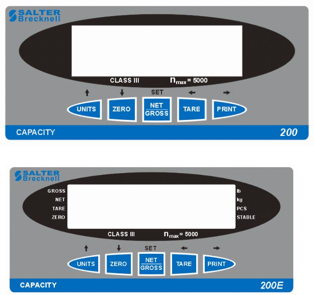
FIGURE 1-1: 200 Front Panel
FIGURE 1-2: 200E Front Panel
1-2

FIGURE 1-3: 200ES Front Panel
1-3

FIGURE 1-4: 200BW Front Panel
FIGURE 1-6: 200SL Front Panel
1-4

CHAPTER 2: INSTALLATION
2.1ABS ENCLOSURE
For indicators contained in the standard ABS enclosure, the rear panel contains all connectors necessary to make the appropriate connections to the weigh platform, printer, remote display and power supply.
Power Switch |
Setup/Calibration |
|
|
Switch |
|
||
|
|
||
DC Jack |
RS 232 |
LOAD CELL |
|
Port |
|||
|
|
Figure 2-1: 200/200E ABS Enclosure Rear Panel
LOAD CELL |
DC Jack |
Serial |
|
||||||||||||
Port |
|
||||||||||||||
|
|
|
|
|
|
|
|
|
|
|
|
|
|
Port |
|
Setup/Calibration Switch

Figure 2-1a: 200BW ABS Enclosure Rear Panel
2.1.1CONNECTING THE WEIGH PLATFORM
NOTE: Make connections only with indicator turned off or unplugged.
The indicators mounted in an ABS enclosure ship with a 15 ft shielded load cell cable for connection to a weigh platform’s load cell(s) or junction box.
1.Plug the cable’s 14-pin Centronics-type connector into the load cell port on the rear panel of the indicator.
2.Wire the bare wires and shield to the weigh platform’s load cell(s) or junction box using the color codes shown in Figure 2-2.
Color |
Wire Name |
|
|
RED |
+Excitation |
BLK |
- Excitation |
GRN |
+Signal |
WHT |
- Signal |
|
|
Figure 2-2: Color Codes for Shielded Load Cell Cable
2-1
3.If you do not wish to use the shielded load cell cable, you may use own, following the pin assignments shown in Figure 2-3. (A 14-pin Male Centronics-type connector is required).
Pin Nos. |
Pin Name |
|
|
1/8 |
+Excitation |
3/10 |
- Excitation |
5/12 |
+Signal |
7/14 |
- Signal |
7 |
5 |
3 |
1 |
|||||||||
|
|
|
|
|
|
|
|
|
|
|
|
|
|
|
|
|
|
|
|
|
|
|
|
|
|
|
|
|
|
|
|
|
|
|
|
|
|
|
|
|
|
|
|
|
|
|
|
|
|
|
|
14 12 10 8
Figure 2-3: Pin assignments for the Load Cell Port
2.1.2CONNECTING THE SERIAL PRINTER, REMOTE DISPLAY OR COMPUTER
The 200 Series indicator comes standard with one full duplex RS-232 serial port, designed for connection to either a PC or a serial printer. The same port may be also used as a simplex, RS-232 port designed for connection to a remote display.
Figure 2-4 shows the serial port pin out. Refer to Appendix B for some suggested cable diagrams. (A 9-pin Male D-type connector is required).
1.Plug the serial printer, remote display or computer communication cable (not included) directly into the D-SUB9 serial port connector.
|
|
5 |
3 |
2 |
Pin No. |
Pin Name |
Signal Level |
|
|
2 |
Receive Data |
RS-232 |
|
|
3 |
Transmit Data |
RS-232 |
|
|
5 |
Signal Ground |
RS-232 |
Front View |
|
|
|
|
||
Figure 2-4: Pin assignments for the D-SUB9 serial port connector
2.1.3CONNECTING THE POWER SUPPLY
The 200 and 200E indicators ship standard with an external AC adapter.
1.Simply plug the AC adapter into the indicator’s DC Power Jack first, and then plug into a standard wall outlet. Make sure that the AC voltage appearing at the wall outlet matches the input voltage marked on the AC adapter.
The 200BW alkaline battery indicator ships as a “batteries not included” unit.
1.Obtain six (6) alkaline “C” cell (UM-2) batteries and install them in the battery compartment located at the rear of the unit. Be sure to observe the polarity indicated inside the battery holder.
2-2

2.2STAINLESS STEEL ENCLOSURE
For indicators contained in a stainless steel enclosure, the rear cover must first be removed to make the appropriate connections to the weigh platform, printer, remote display and power supply. To remove the rear cover, simply remove the screws that secure it to the enclosure and set aside.
NOTE: On earlier units, the rear cover must remain off to access the Setup Menu and calibration procedures.
J4 |
CPU |
|
|
J6 |
JP2 |
EPROM
J8 |
J1 |
J3 |
|
|
|
E+ S+ E- S- SH |
P+ P- |
TXD RXD GND +5 |
|
|
Figure 2-5: 200ES Main Circuit Board Overview
TXD |
|
|
RXD |
|
|
GND |
J3 |
|
nc |
|
|
|
|
|
nc |
|
|
P+ |
J2 |
JP4 |
P- |
|
|
P- |
J1 |
|
|
E+ S+ E- |
S- |
Figure 2-5b: 200SL Main Circuit Board Overview
2-3

2.2.1CONNECTING THE WEIGH PLATFORM
NOTE: Make connections only with indicator turned off or unplugged.
1.Connect your shielded load cell cable (not included) to the appropriate terminal on the main board. Connection assignments for the Load Cell Terminals are shown in Figure 2-6.
J8 |
J1 |
E+ S+ E– S– |
E+ S+ E- S– |
200ES |
200SL |
Figure 2-6: Connection assignments for the Load Cell Terminal
2.2.2CONNECTING THE SERIAL PRINTER, REMOTE DISPLAY OR COMPUTER
The 200 Series indicator comes standard with one full duplex RS-232 serial port, designed for connection to either a PC or a serial printer. The same port may be also used as a simplex, RS-232 port designed for connection to a remote display.
Connection assignments for all serial communication terminals are shown in Figure 2-7.
NOTE: Do not connect any RS-232 equipment to the “+5V” terminal (not shown).
1.Connect your serial printer, remote display or computer communication cable (not included) to the appropriate terminal on the main board.
J3
TXD
RXD
TXD RXD GND
GND  J3
J3
200ES nc
nc
200SL
Figure 2-7: Connection assignments for the serial communication terminal
2.2.3CONNECTING THE POWER SUPPLY
The 200ES indicator ships with an AC line cord attached to the indicator. Simply plug the unit into a standard wall outlet.
The 200SL indicators ship with the rechargeable battery pre-installed. The external power supply (included) can also be used to power the indicator. The adapter acts as the battery charger. Because of this, the rechargeable indicator must use a 12 VDC, 800 mA adapter.
1.Simply plug the AC adapter into the indicator’s DC Power Jack first, and then plug into a standard wall outlet. Make sure that the AC voltage appearing at the wall outlet matches the input voltage marked on the AC adapter.
2-4

CHAPTER 3: CONFIGURATION
3.1CONFIGURATION OVERVIEW
The indicator contains two main setup menus: The Setup (“F”) menu, which configures the indicator to your weigh platform and the User (“A”) menu, which configures the serial communication port and enables some user options. The Setup and User menus consist of several menu selections, each with its own sub-menu of choices.
To set up the indicator, you must first enter the appropriate menu mode. Once there, four of the front panel keys become directional navigators to move around in the menus, and one key is used to save or SET the selections.
3.2SETUP (“F”) MENU
3.2.1ENTERING THE SETUP MENU – ABS ENCLOSURE
4.Power off the indicator.
5.On the rear panel move the Setup/Calibration Switch to the opposite position. See Chapter 2 for location of the Setup/Calibration Switch.
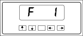
6. Power on the indicator. The indicator shows ” F 1” to indicate that you are in Setup Menu mode.
Note: Access to the Setup/Calibration Switch is inhibited if the indicator has been sealed for commercial use. For more information, please refer to Chapter 8.
3.2.1.1 ENTERING THE SETUP MENU – STAINLESS STEEL ENCLOSURE
1.Power off the indicator.
2.Locate the slide switch on the rear cover and move it to the right.
NOTE: A metal plate held on by two drilled-head screws may conceal the slide switch.
3. Power on the indicator. The indicator shows ” F 1” to indicate that you are in Setup Menu mode.
Note 1: Access to the back cover is inhibited if the indicator has been sealed for commercial use. For more information, please refer to Chapter 8.
Note 2: If your indicator is an older model and does not have the slide switch on the rear cover, follow these instructions instead:
200ES
1.Remove the rear cover and locate jumper JP2.
2.Position the shunt block as shown at right. 


 JP2
JP2
Note: On certain units, the shunt block position will be exactly the opposite.
3. Power on the indicator. The indicator shows ” F 1” to indicate that you are in Setup Menu mode.
3-1
3.2.3NAVIGATING IN THE SETUP MENU
Use the directional keys shown in Figure 3-1 to move around in the Setup Menu Chart shown in Figure 3-2 on the following page.
1.To move to a new “F” heading, use the TARE (left) or PRINT (right) key to move right or left in the Setup Menu Chart.
2.To move to the selection level, press the ZERO (down) key once. The current saved selection is shown.
3.To view the available selections for the current “F” heading, use the TARE (left) or PRINT (right) key to move through the selection field.
4.To save a new selection, press the NET/GROSS (Set) key .To exit without saving, press the UNITS (up) key to return to the current “F” heading.
5.Repeat Steps 1 through 4 until the Setup Menu is programmed.
SET
Figure 3-1: Setup Menu Key Assignments
3-2
 Loading...