

Page 1
CS-200M Mechanical Chair Scale
Installation & Operation Instructions
The CS-200M Mechanical Chair Sale is designed for the mobile challenged who have a difficult time
standing on a conventional scale. It is ideal for use in clinics and nursing facilities. The scale is durable,
having a sturdy enameled steel body, a durable molded plastic seat, heavy-duty footrest, and heavy-duty
caster wheels for easy portability.
Figure 1. Mecha n i cal Chair Scale
August 2011 Version 1.0
Page 2

Installation Instructions
m
r
You will receive your Mechanical Chair Scale partially assembled. Those items that need additional
assembly are:
• Pillar and beam assembly to scale base
• Steelyard rod connection
• Transport handle onto scale base
• Seat and footrest installation
• Arm rest installation
Remove all components from the shipping crate and lay out in a convenient place.
Pillar and Beam Installation
The pillar and beam comes separate from the scale base and must be attached prior to use.
Bea
Pilla
Figure 2. Pillar and Beam Components
Use the following steps to attach the pillar and beam to the scale base.
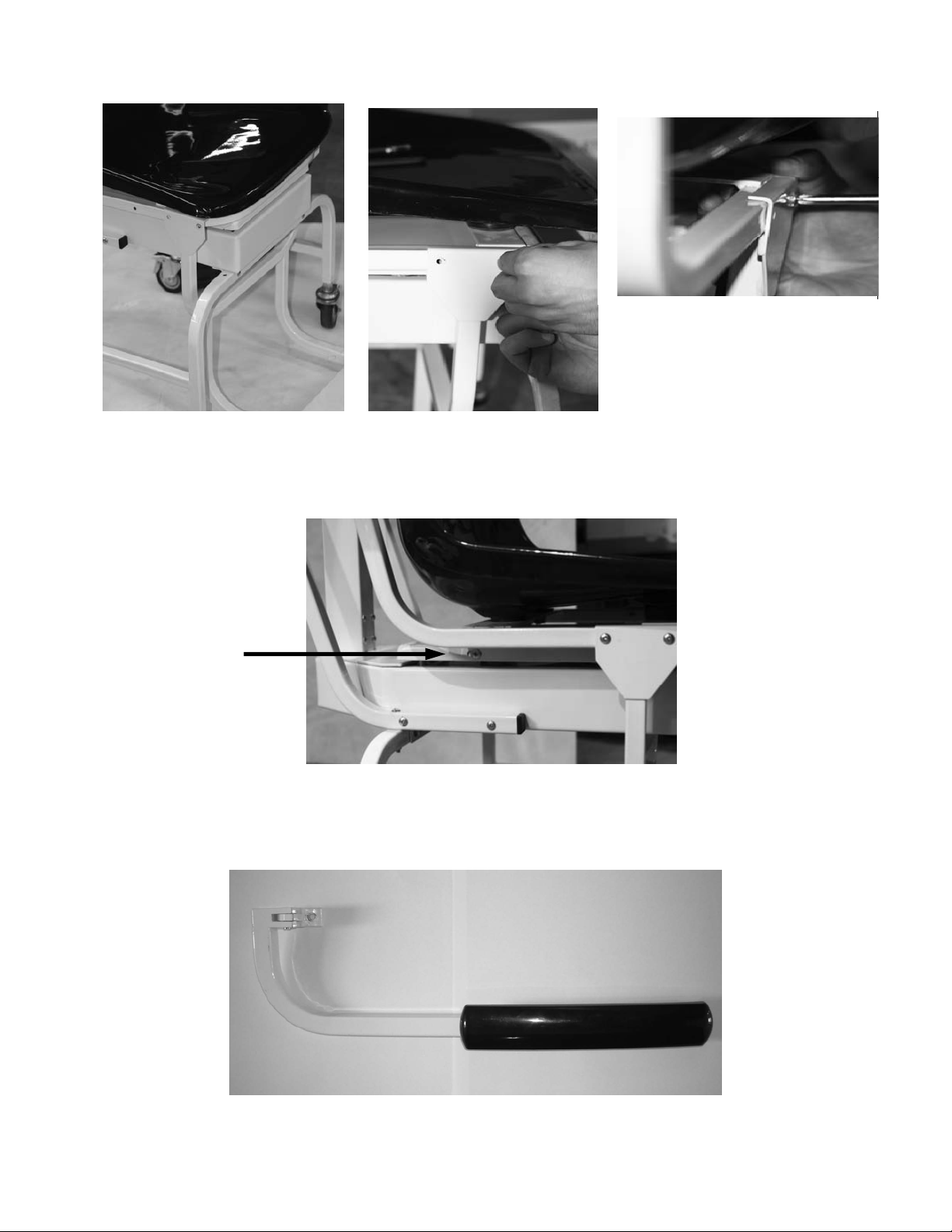
1. Have the scale sitting on the floor in an area that allows you to work freely.
2. Lock casters on the frame to eliminate the unit from rolling while assembling the scale.
Push down on latching assembly
to lock wheels and prevent scale
from rolling.
Figure 3. Lock Casters to Keep From Rolling
2
Page 3
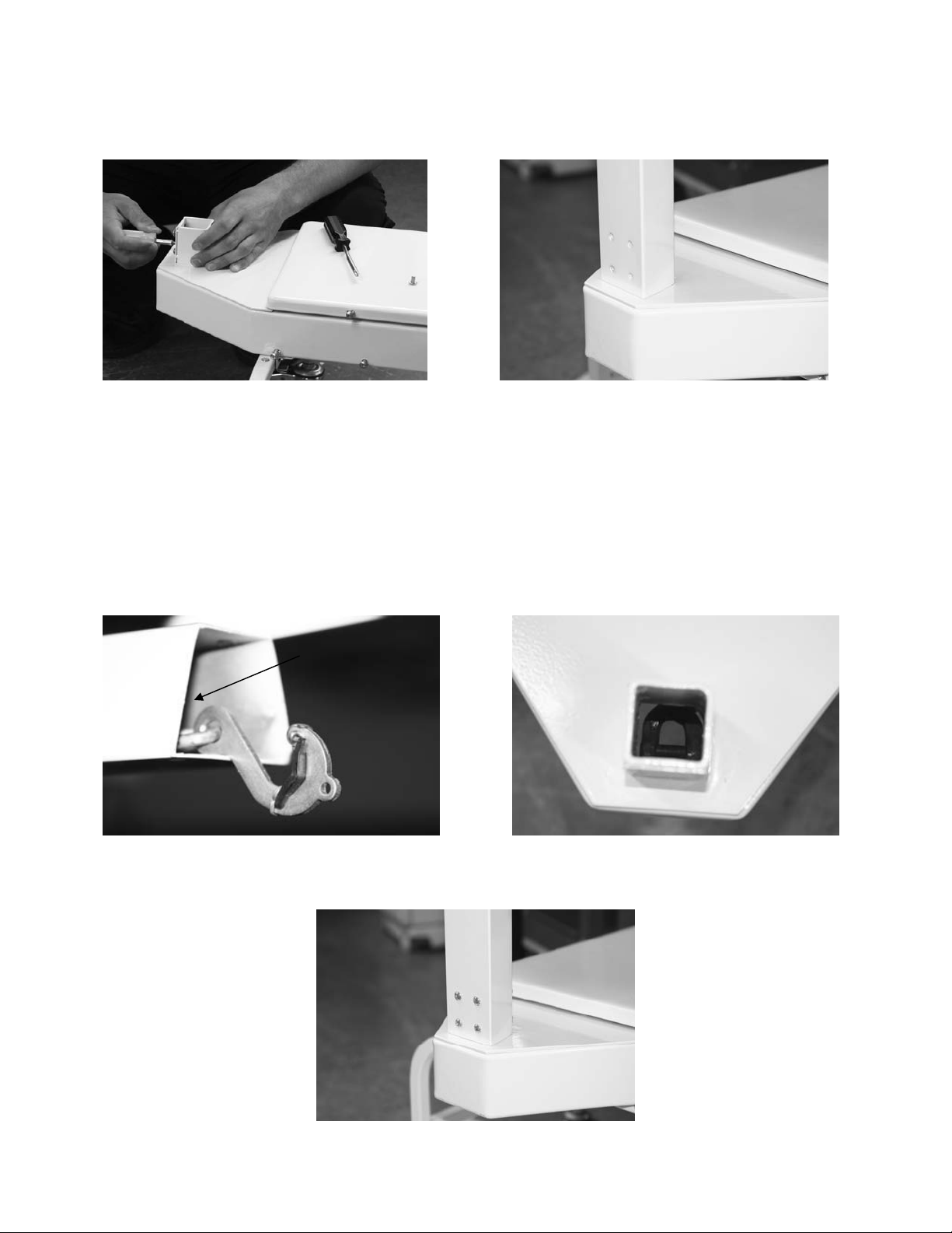
3. Remove the eight screws from the scale base using a phillips head screwdriver (as shown in the left
oo
hand photo) and set screws aside in a safe place.
Figure 4. Remove Screws From Scale Base and Insert Pillar and Beam into Scale Base Assembly
Insert, but don’t fasten the pillar and beam into the scale base assembly as shown in Figure 4 (right
hand side photo).
Steelyard Rod Connection
The steelyard rod is located inside the pillar. Remove the wire tie(s) holding the steelyard rod
during shipment
steelyard rod must be attached to the bottom of the scale. The two photos below show the hook of the
steelyard rod and an inside photo of the ring in the scale bottom. Latch the hook onto the D-shaped ring
shown in the right hand side picture.
. Insert the pillar into the base. Once the pillar is inserted to the scale base, the
Steelyard rod (not
shown)
Steelyard rod
h
k
Figure 5. Attach The Steelyard Rod To the Scale Base D-Ring
Fasten the eight screws once the pillar and beam is connected to the scale base and the steelyard rod is
hooked.
Figure 6. Insert and Tighten The Eight Screws
3
Page 4
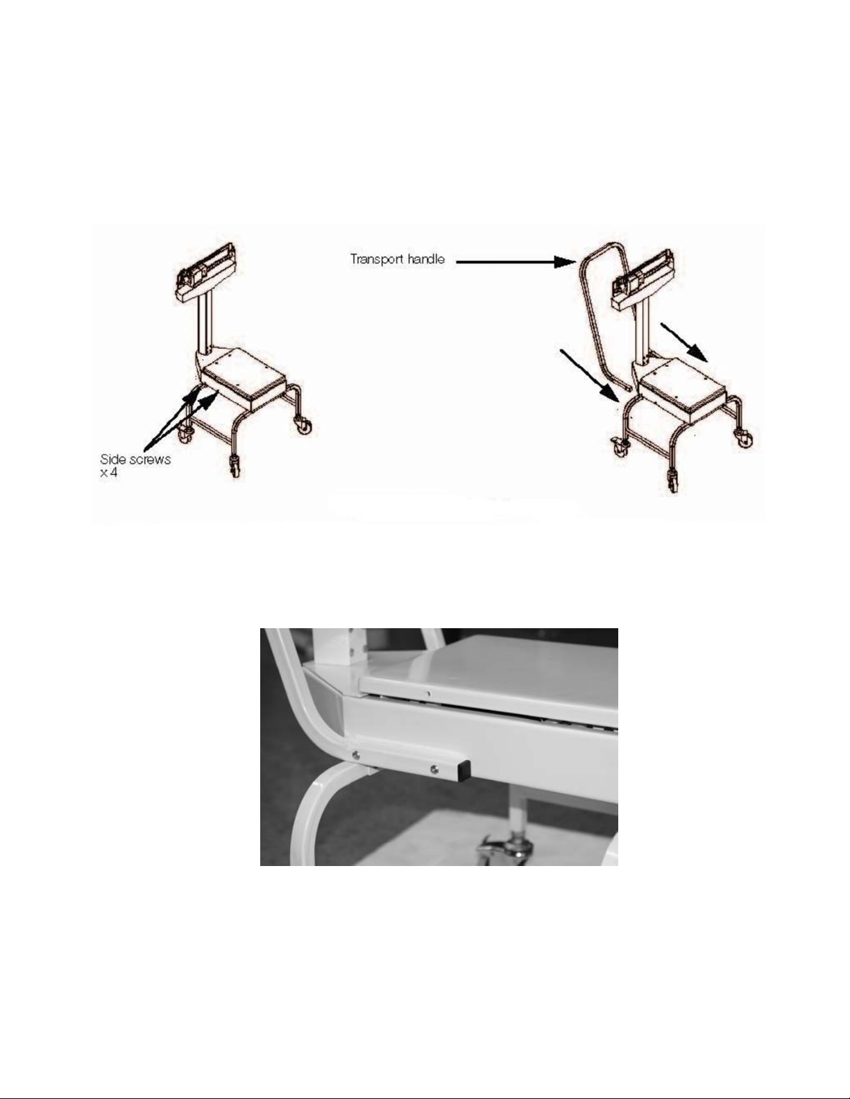
Installing Transport Handle
Once the pillar and beam are attached to the scale support frame and secured, it’s time to attach the
transport handle to the scale support frame (transport handle is illustrated in Figure 8).
1. Remove the four side screws (two on each side as shown in left hand side of Figure 7) from the
scale support frame and set aside. The transport handle will attach to the scale support frame using
those screws.
Figure 7. Transport Handle Installation
2. Insert the transport handle into the two sides of the scale support frame as shown in right side of
Figure 7.
3. Insert and tighten the four screws using a phillips screwdriver as shown in Figure 8.
Figure 8. Insert and Tighten Four Screws for Securing the Transport Handle to the Scale Support Frame
The transport handle should fit snuggly against the scale support frame.
4
Page 5
Seat and Footrest Installation
Once the transport handle is attached the next step is to install the molded seat to the scale support
frame.
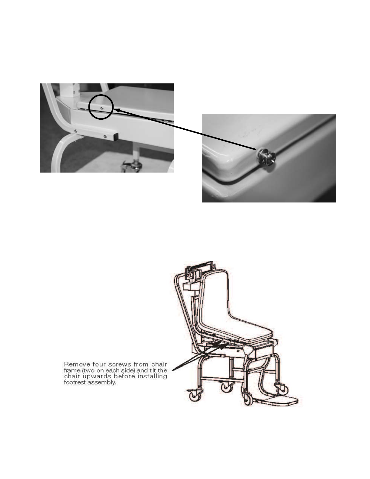
1. Remove the four screws from the movable scale support frame platform and set aside.
Four screws on scale support
Frame – only one screw shown
Figure 9. Removable Screws on The Movable Scale Support Frame
2. Set the chair onto the scale support frame platform but do not fasten the screws as the footrest
assembly will also have to be put into place prior to tightening all screws.
3. Remove screws from the chair frame (shown in Figure 10) and set aside.
4. Tilt the chair upwards as shown in Figure 10. This will allow the installer to get the footrest assembly in
place prior to securing the chair to the platform
Figure 10. Tilt the Chair Upward Before Installing the Footrest Assembly
5. Slide the footrest assembly onto the chair scale base as shown in Figure 10.
Note that the footrest assembly for the footrest is hanging on the metal chair channel and lined up
with the screw holes on the channel of the chair scale frame as shown in Figure 11.
5
Page 6
Push footrest assembly back
so that the holes line up.
Figure 11. Slide the Footrest Assembly So That Holes Line Up
Once the footrest is secured and the screws tightened for it, secure the molded seat onto the chair
scale frame.
6. Secure the four screws (shown below).
Secure screws (only
one shown)
Figure 12. These Screws Hold The Molded Chair to the Scale Base
Arm Rest Installation
The last item to be installed on the mechanical chair scale are the two arm r ests.
Figure 13. Detachable Arm Rest for the Mechanical Chair Scale
Use the following steps to attach the two arm rests to the mechanical chair scale molded seat.
6
Page 7
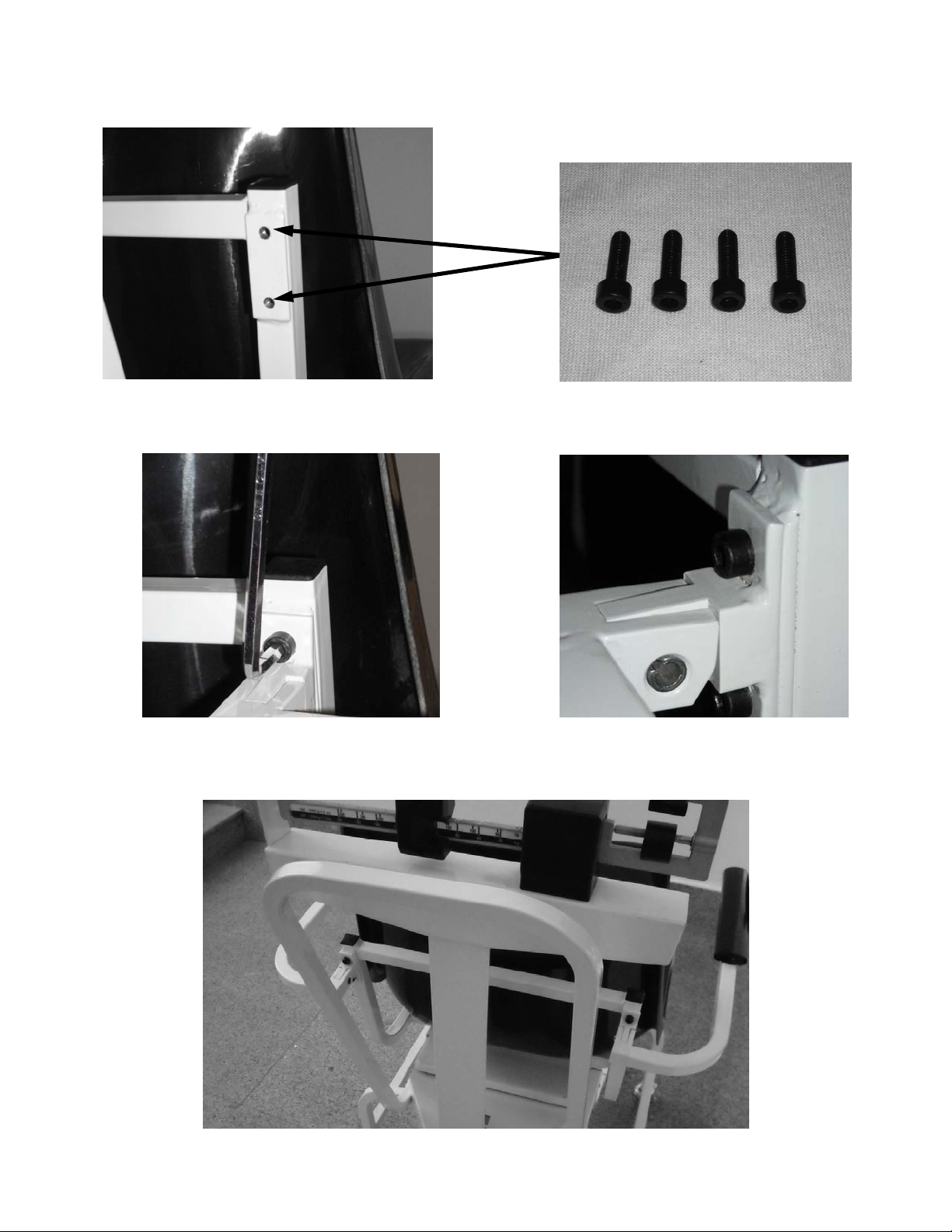
1. Locate the bolt hole (x 4) location on the back of the molded chair.
two bolts for each arm rest
Figure 14. Hole Location and Four Bolts Used for Securin g Arm Re st to Ch air
2. Secure the arm rests to the molded chair using the four bolts (provided and shown in Figure 14), using
the 5mm allen wrench that’s been provided in this packaging.
Figure 15. Secure Arm Rests to the Molded Chair
3. The arm rests are now in position and can be moved up and down.
Figure 16. Arm Rests Are Secured to the Molded Chair Seat
7
Page 8
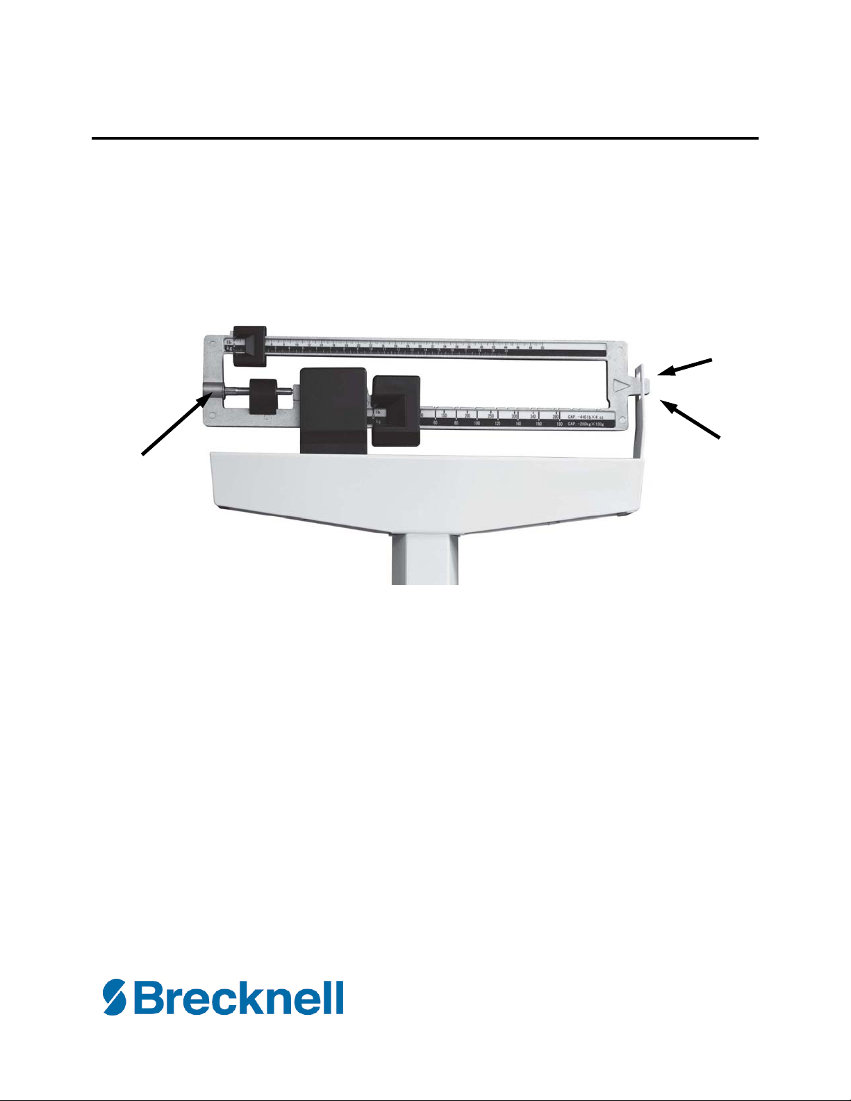
Zero Adjustment
p
To ensure accurate weighments, a zero adjustment should be done to the scale upon arrival and setup.
To perform a zero adjustment, perform the following steps.
1. Ensure the scale is sitting on a level surface.
2. Check the eye loop area of the scale to ensure that the scale pointer is equally balanced between the
eye loop area.
Scale
ointer
Zero
Eye Loop Area
Adjusting
Screw
Figure 17. Eye Loop Area and Zero Adjusting Screw Location
3. If the scale is not balancing properly, then the small zero balance weight must be adjusted. Turn the
zero adjusting screw (shown in Figure 17) using a flat head screwdriver. By adjusting the screw, the
zero balance weight will move accordingly.
4. The scale is now ready to weigh patients.
5. Have the patient sit down on the molded seat. The patient should be completely seated in the
chair, not leaning forward, and having feet firmly positioned on the footrest assembly.
USA
Brecknell
1000 Armstrong Drive
Fairmont MN 56031
Toll Free: 800-637-0529
Tel: 507-238-8702
Email:sales@brecknellscales.com
Fax: 507-238-8271
www. brecknellscales.com
8
Web site: www. brecknellscales.co.uk
Tel: +44 (0) 845 246 6717
Email: sales@brecknellscales.co.uk
UK and Europe
Brecknell
Foundry Lane
Smethwick
West Midlands, B66 2LP.
Fax: +44 (0) 845 246 6718
 Loading...