


SUMMARY OF FEATURES
Summary of Features
GRQ3121 (1U, single channel, one input, two outputs)
GRQ3122 (2U, dual channel, one input & output per channel)
GRQ3121-S (1U, blank front panel slave, single channel, one input, two outputs)
GRQ3122-S (1U, blank front panel slave, dual channel, one input & output per channel)
GRQ2 Remote for WindowsTM Software included with every unit; runs up to 8 Graphi-Q2s per COM port (maximum of 2 COM ports)
•All front panel controls are analog-style; signal path is digital
•“Tweek-n-Peek” feature: Front panel adjustments of all parameters are shown in LED display screen
•24-bit A/D and D/A conversion, 32-bit processing
•20 to 20 KHz Frequency Response
•+18 dBV Maximum Signal Input & Output
•Floating Point SHARC Processor
•>110 dB dynamic range
Each channel provides (now with fully independent processing on 1x2 units):
•31-band graphic EQ, with ± 6 or 12 dB range (selectable)
•Crossover: Bessel, Butterworth, and Linkwitz Reily filters; slopes to 48 dB/octave (Software only)
•High Cut Filter (3KHz to 20KHz) and Low Cut Filter (20 Hz to 1KHz)
•FBX Feedback Exterminator: up to 12 Filters, with Setup Mode (Auto Setup Mode via remote control)
•Parametric Filters: up to 12 filters, numeric or graphic control (Software only)
•Compressor/Limiter, with controls for ratio, threshold, and gain (attack, release, and knee adjustable with remote)
•Digital Delay, with up to 1 second delay, adjustable in 20 microsecond increments
•Bypass: dedicated switches for FBX, EQ, and Delay with built in LED indicators
•LED Segmented Indicators: FBX Filters, Level, Gain Reduction
•LED Point Indicators: FBX Setup, Remote, EQ Range
•LED Character Display: Delay setting, EQ fader boost/cut, High Cut Filter setting Low Cut Filter setting, Compressor Ratio, Threshold, Gain, and Staus Messages.
Back Panel:
•XLR & 1/4" TRS inputs & outputs
•RS-232 Serial input & output (additional serial input on the slave front panels)
•Remote switching (8-position contact closure switch; allows switch selection of all 20 stored GraphiQ2 presets)
Graphi-Q2 Remote Software Features:
All front panel controls, plus more, including:
•FBX filter depth & width adjustments; switchable to parametric filters (depth, width & frequency adjustments)
•Graphic EQ filter width adjustments
•Password protection
•View & edit frequency response curves
•20 user-defined stored presets
•Control and link up to 8 Graphi-Q2s (16 channels of audio) per COM port (1 or 2 ports can be used)
•Future-proofFREEFlashRAMupgradecapability: upgradeyourfirmwareandsoftwarefromtheSabine website (www.Sabine.com)!
Operating Guide Version 2: for Sabine Graphi-Q2s with:
•GRQ2 Firmware Version 2.20 and up
•GRQ2 Remote Software Version 5.0 and up
1
B1-GRQ-2-OpGuide-v1-060519.pmd

DECLARATION OF CONFORMITY
EC - DECLARATION OF CONFORMITY
CE MARKING
We, the Manufacturer
SABINE, INC.
13301 NW US HIGHWAY 441 ALACHUA, FLORIDA USA
declare that the product
EQUALIZER
SABINE MODEL GRQ3100
Is in conformity with
Council Directive: 73/23/EEC and 89/336/EEC (EMC Directives)
Standards to which conformity is declared:
EN 60065: 1993
EN 60742: 1995
EN 55103-1: 1997
EN 55022: 08:94 + a1:05:05
EN 55103-2: 1997
Manufacturer's Signature:
Date: October 31, 2002 Name: Doran Oster, Sabine President
2

|
TABLE OF CONTENTS |
Summary of Features ......................................................................................................................................................... |
1 |
Section One: Introduction ................................................................................................................................................. |
4 |
Section Two: Analog vs. Digital Signal Processing (DSP) .............................................................................................. |
5 |
Section Three: Front & Back Panel Views ........................................................................................................................ |
6 |
Section Four: Block Diagram/Internal Signal Path .......................................................................................................... |
8 |
Section Five: Installation .................................................................................................................................................. |
9 |
5.1. BETWEEN MIXER OUTPUT AND POWER AMPLIFIER ............................................................................................................ |
9 |
5.2. TWO CHANNEL GRAPHI-Q2: MAINS AND MONITORS. .......................................................................................................... |
9 |
5.3. USE WITH A POWERED MIXER .............................................................................................................................................. |
10 |
5.4. USE AT A MIXER INSERT POINT ............................................................................................................................................. |
10 |
5.5. SINGLE CHANNEL GRAPHI-Q2: ONE INPUT TWO OUTPUTS ............................................................................................... |
11 |
5.6. WHAT NOT TO DO ..................................................................................................................................................................... |
11 |
Section Six: Using Graphi-Q2 Front Panel Controls ....................................................................................................... |
12 |
6.1. FRONT PANEL CALIBRATION .................................................................................................................................................. |
12 |
6.2. GRAPHIC EQUALIZER CONTROLS ......................................................................................................................................... |
12 |
6.3. HIGH CUT/LOW CUT FILTERS ................................................................................................................................................. |
13 |
6.4. FEEDBACK CONTROL AND PARAMETRIC EQUALIZATION .................................................................................................. |
13 |
6.5. COMPRESSOR/LIMITER CONTROLS ..................................................................................................................................... |
17 |
6.6. DIGITAL DELAY CONTROLS .................................................................................................................................................... |
17 |
6.7. BYPASS ..................................................................................................................................................................................... |
17 |
6.8. FRONT PANEL DEFAULT SETTINGS ADJUSTABLE ONLY BY SOFTWARE .......................................................................... |
18 |
6.9. FRONT PANEL CONTROL OPTIONS ....................................................................................................................................... |
18 |
Section Seven: GRQ2-Remote Software Installation ...................................................................................................... |
19 |
7.1. SYSTEM REQUIREMENTS AND RECOMMENDATIONS ........................................................................................................ |
19 |
7.2. CONNECTIONS ......................................................................................................................................................................... |
19 |
7.3. INSTALLING THE SOFTWARE .................................................................................................................................................. |
20 |
Section Eight: Using GRQ2-Remote Software ................................................................................................................ |
21 |
8.1. WELCOME SCREEN/NETWORK CHAIN SCREEN ................................................................................................................. |
21 |
8.2. GRQ MAIN SCREEN & MAIN FUNCTIONS .............................................................................................................................. |
22 |
8.3. LINKING PARAMETERS AND CONTROL WITH THE GRQ-REMOTE SOFTWARE ................................................................ |
29 |
8.4. RESET PARAMETERS .............................................................................................................................................................. |
33 |
8.5. PRINTING GRAPHI-Q SETTINGS FOR DOCUMENTATION ..................................................................................................... |
33 |
8.6. STORING AND RECALLING GRQ PRESETS ......................................................................................................................... |
33 |
8.7. ASSIGNING NAMES TO GRAPHI-QS ....................................................................................................................................... |
36 |
8.8. PASSWORD PROTECTION WITH GRQ-REMOTE SOFTWARE .............................................................................................. |
37 |
8.9. NAVIGATING WITH MULTIPLE UNITS ...................................................................................................................................... |
38 |
8.10. UPGRADING GRAPHI-Q FIRMWARE & SOFTWARE ............................................................................................................. |
38 |
Section Nine: Suggestions for Optimal Use of the Graphi-Q2 ....................................................................................... |
39 |
9.1. SYSTEM SETUP SUGGESTIONS ............................................................................................................................................. |
39 |
9.2. WIDE & NARROW FILTERS: GRAPHIC, PARAMETRIC, AND FBX ......................................................................................... |
40 |
9.3. RECOMMENDED EQ USAGE .................................................................................................................................................. |
41 |
9.4. USING DIGITAL DELAY ............................................................................................................................................................. |
42 |
9.5. USING THE COMPRESSOR/LIMITER ...................................................................................................................................... |
47 |
SectionTen: TroubleshootingTips .................................................................................................................................. |
51 |
Section Eleven: Graphi-Q2 Engineering Specifications ................................................................................................ |
53 |
SectionTwelve: Cautions &Warranty ............................................................................................................................... |
54 |
3
B1-GRQ-2-OpGuide-v1-060519.pmd

SECTION ONE: INTRODUCTION
Section One: Introduction
Congratulations on your purchase of the Sabine Graphi-Q2. This product represents our latest breakthrough in our never-ending quest to improve the world’s sound.
Aside from the powerful array of features packed into a single unit (graphic EQ, FBX filters, parametric filters, high and low cut filters, delay, compression, and limiting), the Graphi-Q2 also offers a choice of user interfaces.
Computer control: learn to love it. As the world becomes an increasingly digital place, the computer is omnipresent. Some regard this as a mixed blessing. In audio applications, the downside of computercontrolled digital audio stems from the unfamiliarity and operational limitations of its control interface. After years of experience with analog controls, many sound engineers prefer the “hands-on” approach to control audio with knobs and faders. It’s intuitive and direct. To the analog lover, typing commands on a keyboard feels awkward and may require redirecting one’s attention to the control interface, rather than the sound emerging from the speakers.
On the other hand, there is no question that the digital signal processing available through a computer interface offers improved precision and reliability of control over your audio. Equalization adjustments in the digital realm are exceptionally accurate, offer pinpoint resolution, and minimize phase distortion and frequency drift. Compressor parameters not only can be set quite precisely, but also offer an expanded range of adjustment and ease of storage and recall that are much more difficult to achieve with analog technology. And, with the Sabine FBX algorithm, one of the most serious problems of audio amplification — that lovely howling sound we call feedback — can be removed with the precision and delicacy of laser surgery.
Analog AND Digital - Best of Both Worlds. The Graphi-Q2 combines the best of both worlds. If you need to put your hands on faders and knobs to fully experience audio, we offer you the ease and comfort of our “analog-style” front panel. Push, pull, turn, and tweak to your heart’s content!
If your fingers naturally gravitate toward computer keyboards, the Graphi-Q2 offers your kind of user interface as well. Each Graphi-Q2 comes equipped with an RS-232 serial interface and the Sabine Graphi-Q2 Remote for WindowsTM software. All the front panel controls, and some important additional ones, can be adjusted from your computer keyboard. And if you’re seriously addicted to the thrill of punching keys, you can save some money as you indulge yourself with a Graphi-Q2 Blank Front Panel Slave unit. Only controllable via computer, these models make mis-adjustment by unauthorized, untrained, or unthinking individuals impossible!
Whatever your control preference, the Graphi-Q2 opens up a world of signal processing power previously unavailable at its exceptional price. All specifications are top notch (24-bit A/D and D/A, 32bit internal processing) and all of its functions operate concurrently and ergonomically. So allow us to suggest you read and study this entire manual to understand the whole story. Enjoy!
4

SECTION TWO: ANALOG VS. DIGITAL SIGNAL PROCESSING
Section Two: Analog vs. Digital Signal Processing (DSP)
The ongoing debate continues: what sounds better, digital or analog signal processing? Audio engineers ALL have an opinion on this, but the lack of documented research on the topic makes conclusions tentative. Nonetheless, the audio industry is slowly moving to digital as circuit designs continuously improve and technology advances into the realm of 24-bit resolution — which provides finer audio detail, particularly at low levels of dynamic range. The tentative conclusion we would suggest is that the sound of digital circuits is widely variable, encompassing the capacity to sound remarkably like analog circuits … and much more. Beyond these considerations, however, there are undeniable advantages to DSP … and one disadvantage that we believe we have solved with the Graphi-Q2.
THE ADVANTAGES
1.GREATER PRECISION AND REPEATABLE ACCURACY. Analog circuitry produces less exact and repeatable adjustment. Identical analog circuits may produce different results when processing an identical audio signal, due to the tolerance of components comprising the analog circuit. Digital circuits rely on repeatable mathematical calculations and thus are more consistent. For equalizers, this means that the slope, shape, and symmetry of digital EQs are consistent across frequencies, and from one application to the next.
In addition to the precision attributable to digital processing, the Graphi-Q2 offers a high degree of operational precision and repeatability as well. On an analog graphic equalizer, the operator must infer the value of a knob or EQ fader setting from its position. With the Graphi-Q2 Tweek-n-Peek feature, the exact value of each knob is visually displayed as each setting is adjusted.
2.LESS PHASE DISTORTION. All equalizers cause some degree of phase shifting. In analog filters, this phase shift exceeds the width of the filter — often by a considerable margin. In other words, the phase shift encompasses frequencies beyond the boost or cut range of the filter. With digital filters, this phase shift can be restricted to within the filter width.
3.LESS FILTER DRIFT. Analog circuits rely on components that vary as they age and/or are subjected to different ambient temperatures. This variation can in turn cause analog filters to drift from their original settings. In contrast, digital filters are based on mathematical formulas and will remain constant over time and changing temperatures.
4.LESS NOISE. As analog parts wear, get dirty, or corrode, readjusting them can introduce noise into the signal path. All audio engineers are familiar with the sound of a “scratchy fader.” Digital controls affect the signal, but are not actually in the audio path and thus cannot introduce noise.
5.RECALL AND STORAGE OF SETTINGS. Because digital filters can be represented mathematically, settings are easily stored, recalled, and copied to other channels or units. Analog filters are dependent on the physical position of potentiometers and sliders, and storing and recalling settings requires servo motors and automated repositioning of controls. This is both more expensive to build and produces less accurate results.
6.COST. As technology improves, features increase and prices plummet. Nowhere is this trend more apparent than in the digital world. DSP circuitry is generally smaller, less costly, and more powerful than comparable analog circuitry, which means you get a lot more bang for your buck (or DeutschMark, pound, or peso) with a digital box. Compare the price of the Graphi-Q2 to a high quality analog graphic equalizer, and you’ll see what we mean — especially when you add a compressor, delay, FBX and parametric EQ, and software interface to the comparison.
THE DISADVANTAGES
1.FAMILIARITY AND EASE OF USE. The sole disadvantage of digital processors that few if any sound engineers will argue has to do with the familiarity and user-friendliness of the digital control interface. Many powerful DSP products are menu-driven and difficult to use. One very special feature of the Graphi-Q2 GRQ3122 and GRQ3121 models is the familiar analog-style interface of the front panel. The control surface looks, feels, and operates like a graphic equalizer from the 1970’s — with the power and features of 21st century technology. If you’re a 21st century technophile who loves computers and knobs, then you won’t be disappointed either—just plug in a serial cable, load up the software, and you’ll find a whole new world of hacker-pleasing software control waiting for your command.
5
B1-GRQ-2-OpGuide-v1-060519.pmd
SECTION THREE: FRONT AND BACK PANEL VIEWS
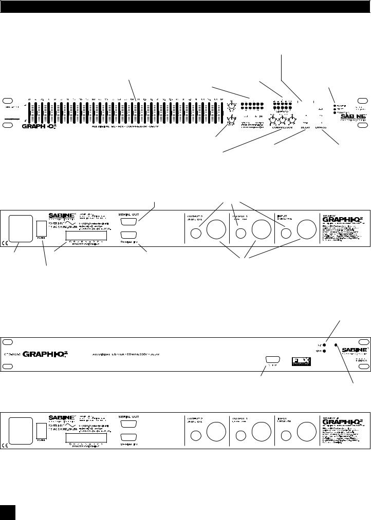
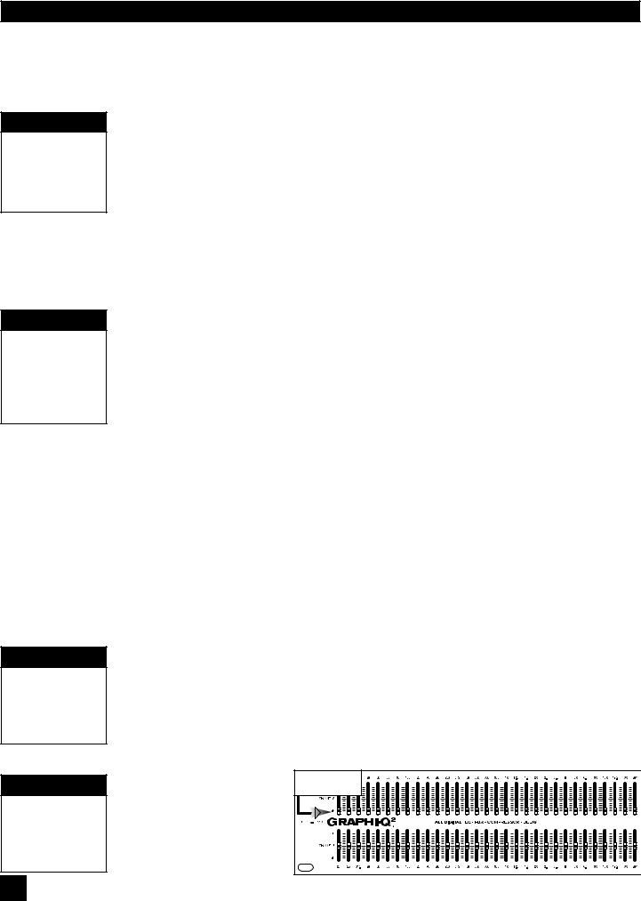
Section Three: Front & Back Panel Views
Digital Delay / Tweek-n-Peek Display
Digital delay time value displayed. Also momentarily displays current firmware at power up, or value of any front panel control altered.
|
|
|
|
|
|
|
|
|
|
|
|
|
|
|
|
|
|
|
|
|
|
|
|
|
|
|
|
|
|
|
|
|
|
|
|
EQ faders |
|
|
|
|
|
|
FBX Section |
Input signal & |
Status LEDs |
|||||||||||||||||||||||||||||||||||||||||||||||||||||||||||||||||||||||||
|
|
|
|
|
|
|
|
|
|
|
|
|
|
|
|
|
|
|
|
|
|
|
|
|
|
|
|
|
|
|
|
|
|
|
|
Adjust boost/cut for 31 |
|
|
|
|
|
|
12 filter indicators |
gain reduction |
FBX SETUP - Fast FBX Setup |
|||||||||||||||||||||||||||||||||||||||||||||||||||||||||||||||||||||||||
|
|
|
|
|
|
|
|
|
|
|
|
|
|
|
|
|
|
|
|
|
|
|
|
|
|
|
|
|
|
|
|
|
|
|
|
specific frequencies |
|
|
|
|
|
|
Reset, Width, |
indicators |
REMOTE - GRQ Remote active |
|||||||||||||||||||||||||||||||||||||||||||||||||||||||||||||||||||||||||
GRQ3121 Front Panel |
|
|
|
|
|
|
Set, & Lock Fixed Filter |
|
|
|
|
|
|
|
|
|
|
|
EQ Range - EQ fader range indicator |
|||||||||||||||||||||||||||||||||||||||||||||||||||||||||||||||||||||||||||||||||||||||||||||||||||
|
|
|
|
|
|
|
|
|
|
|
|
|
|
|
|
|
|
|
|
|
|
|
|
|
|
|
|
|
|
|
||||||||||||||||||||||||||||||||||||||||||||||||||||||||||||||||||||||||||||||||||||||||
|
|
|
|
|
|
Controls |
|
|
|
|
|
|
|
|
|
|
|
|
|
|
|
|
|
|
|
|
|
|
|
|
|
|||||||||||||||||||||||||||||||||||||||||||||||||||||||||||||||||||||||||||||||||||||||
|
|
|
|
|
|
|
|
|
|
|
|
|
|
|
|
|
|
|
|
|
|
|
|
|
|
|
|
|
|
|
|
|
|
|
|
|
|
|
|
|
|
|
|
|
|
|
|
|
|
|
|
|
|
|
|
|
|
|
|
|
|
|
|
|
|
|
|
|
|
|
|
|
|
|
|
|
|
|
|
|
|
|
|
|
|
|
|
|
|
|
|
|
|
|
|
|
|
|
|
|
|
|
|
|
|
|
|
|
|
|
|
|
|
|
|
|
|
|
|
|
|
|
|
|
|
|
|
|
|
|
|
|
|
|
|
|
|
|
|
|
|
|
|
|
|
|
|
|
|
|
|
|
|
|
|
|
|
|
|
|
|
|
|
|
|
|
|
|
|
|
|
|
|
|
|
|
|
|
|
|
|
|
|
|
|
|
|
|
|
|
|
|
|
|
|
|
|
|
|
|
|
|
|
|
|
|
|
|
|
|
|
|
|
|
|
|
|
|
|
|
|
|
|
|
|
|
|
|
|
|
|
|
|
|
|
|
|
|
|
|
|
|
|
|
|
|
|
|
|
|
|
|
|
|
|
|
|
|
|
|
|
|
|
|
|
|
|
|
|
|
|
|
|
|
|
|
|
|
|
|
|
|
|
|
|
|
|
|
|
|
|
|
|
|
|
|
|
|
|
|
|
|
|
|
|
|
|
|
|
|
|
|
|
|
|
|
|
|
|
|
|
|
|
|
|
|
|
|
|
|
|
|
|
|
|
|
|
|
|
|
|
|
|
|
|
|
|
|
|
|
|
|
|
|
|
|
|
|
|
|
|
|
|
|
|
|
|
|
|
|
|
|
|
|
|
|
|
|
|
|
|
|
|
|
|
|
|
|
|
|
|
|
|
|
|
|
|
|
|
|
|
|
|
|
|
|
|
|
|
|
|
|
|
|
|
|
|
|
|
|
|
|
|
|
|
|
|
|
|
|
|
|
|
|
|
|
|
|
|
|
|
|
|
|
|
|
|
|
|
|
|
|
|
|
|
|
|
|
|
|
|
|
|
|
|
|
|
|
|
|
|
|
|
|
|
|
|
|
|
|
|
|
|
|
|
|
|
|
|
|
|
|
|
|
|
|
|
|
|
|
|
|
|
|
|
|
|
|
|
|
|
|
|
|
|
|
|
|
|
|
|
|
|
|
|
|
|
|
|
|
|
|
|
|
|
|
|
|
|
|
|
|
|
|
|
|
|
|
|
|
|
|
|
|
|
|
|
|
|
|
|
|
|
|
|
|
|
|
|
|
|
|
|
|
|
|
|
|
|
|
|
|
|
|
|
|
|
|
|
|
|
|
|
|
|
|
|
|
|
|
|
|
|
|
|
|
|
|
|
|
|
|
|
|
|
|
|
|
|
|
|
|
|
|
|
|
|
|
|
|
|
|
|
|
|
|
|
|
|
|
|
|
|
|
|
|
|
|
|
|
|
|
|
|
|
|
|
|
|
|
|
|
|
|
|
|
|
|
|
|
|
|
|
|
|
|
|
|
|
|
|
|
|
|
|
|
|
|
|
|
|
|
|
|
|
|
|
|
|
|
|
|
|
|
|
|
|
|
|
|
|
|
|
|
|
|
|
|
|
|
|
|
|
|
|
|
|
|
|
|
|
|
|
|
|
|
|
|
|
|
|
|
|
|
|
|
|
|
|
|
|
|
|
|
|
|
|
|
|
|
|
|
|
|
|
|
|
|
|
|
|
|
|
|
|
|
|
|
|
|
|
|
|
|
|
|
|
|
|
|
|
|
|
|
|
|
|
|
|
|
|
|
|
|
|
|
|
|
|
|
|
|
|
|
|
|
|
|
|
|
|
|
|
|
|
|
|
|
|
|
|
|
|
|
|
|
|
|
|
|
|
|
|
|
|
|
|
|
|
|
|
|
|
|
|
|
|
|
|
|
|
|
|
|
|
|
|
|
|
|
|
|
|
|
|
|
|
|
|
|
|
|
|
|
|
|
|
|
|
|
|
|
|
|
|
|
|
|
|
|
|
|
|
|
|
|
|
|
|
|
|
|
|
|
|
|
|
|
|
|
|
|
|
|
|
|
|
|
|
|
|
|
|
|
|
|
|
|
|
|
|
|
|
|
|
|
|
|
|
|
|
|
High & Low Cut Filters |
|
|
|
Compressor Section |
Digital Delay |
Bypass Controls |
|
up & down controls. |
|
|
|
Level Indicators |
|
|
|
EQ range |
|
|
|
Ratio, Threshold, & Gain controls |
|
|
|
Press up & down buttons simulta- |
||
|
|
||
|
|
neously to toggle EQ range between |
|
RS-232 Serial Out |
+6 dB and +12 dB |
|
|
|
|
||
Connect to next |
|
|
|
GRQ in chain |
1/4” TRS connectors |
|
|
GRQ3121 Back Panel
|
|
XLR |
XLR |
XLR |
Power connector |
Phoenix block connectors |
RS-232 Serial In |
|
|
& fuse |
For contact closure switch |
Connect to serial port |
XLR connectors |
|
Power Switch |
of PC, or previous |
|
|
|
|
|
GRQ in chain |
|
|
Clip LED-lights at 3 dB below clipping Signal LED-lights when input is above 30 dBV peak
GRQ3121-S Front Panel
Additional |
|
RS-232 Serial In |
Power On LED |
GRQ3121-S Back Panel
6

SECTION THREE: FRONT AND BACK PANEL VIEWS
GRQ3122 Front Panel
GRQ3122 Back Panel
GRQ3122-S Front Panel
GRQ3122-S Back Panel
7
B1-GRQ-2-OpGuide-v1-060519.pmd
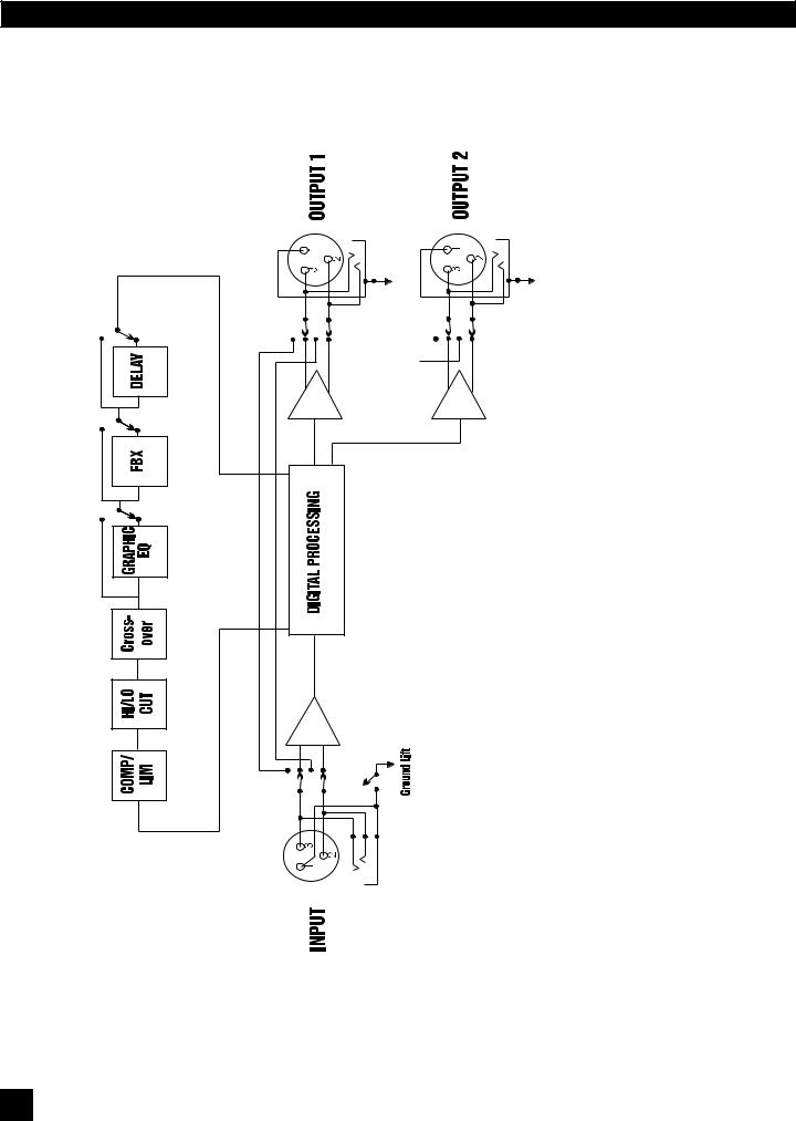
SECTION FOUR: BLOCK DIAGRAM/INTERNAL SIGNAL PATH
Section Four: Block Diagram/Internal Signal Path
8
Section Five: Installation
Section Five: Installation
The Graphi-Q2 should be placed in a well-ventilated, well-grounded equipment rack, preferably within easy reach of the sound engineer. Graphi-Q2 slave units need not be as immediately accessible, since control is through a computer interface.
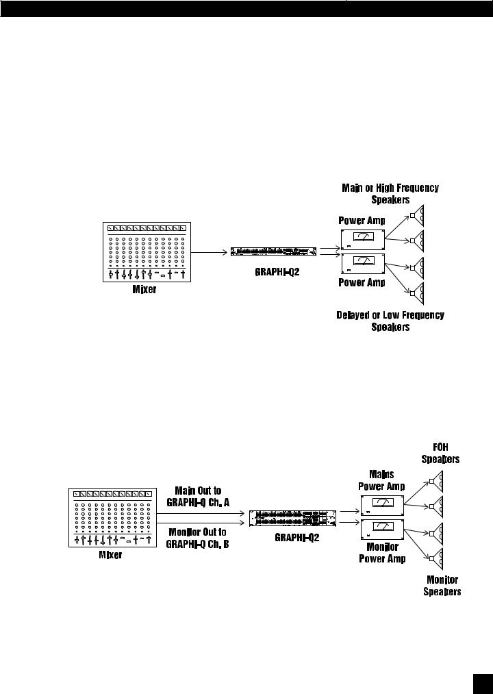
5.1.BETWEEN MIXER OUTPUT AND POWER AMPLIFIER
The most common placement of the Graphi-Q2 in a sound system is between the output of a mixing console and the input to a power amplifier. In this configuration the GRQ2 can provide all your system processing, including delay and crossover. A typical configuration will look like this:
This configuration can also be simplified using a single channel (one input, using only one output) Graphi-Q2.
5.2. TWO CHANNEL GRAPHI-Q2: MAINS AND MONITORS.
Alternatively, with a two-channel Graphi-Q2, you may elect to route one mixer output through Graphi-Q2 channel A into a power amp driving your main speakers, and your mixer monitor output into Graphi-Q2 channel B, routed to your monitor speakers. This configuration is diagrammed below:
9
B1-GRQ-2-OpGuide-v1-060519.pmd
SECTION FIVE: INSTALLATION
5.3. USE WITH A POWERED MIXER
With a powered mixer, the Graphi-Q2 must be inserted between the “Line Out” jack(s) (line level output, before the signal goes through the amplifier) and the “Amplifier In” jack(s), as shown below:
NOTE: Not all powered mixers will offer such patch points, or they may label them differently. When in doubt consult the manual of the console manufacturer.
5.4. USE AT A MIXER INSERT POINT
The Graphi-Q2 may also be used at a mixer insert point, either for a single input channel, or for a group or bus insert point. This will dedicate all of the features and processing power of the Graphi-Q2 to one or two single channels on your mixer, or to a subgroup of inputs (for example, all the drums in your mix). The patching will look like this:
10
SECTION FIVE: INSTALLATION
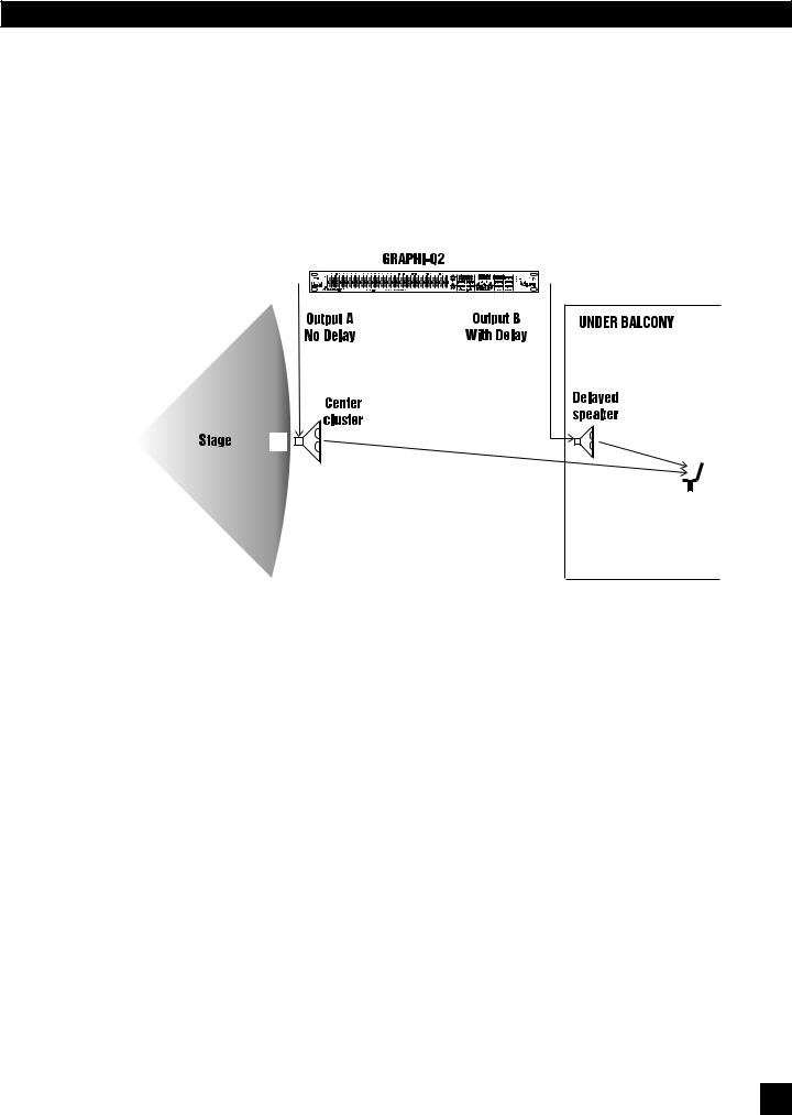
5.5. SINGLE CHANNEL GRAPHI-Q2: ONE INPUT - TWO OUTPUTS
The single channel Graphi-Q2 also offers a unique setup option, since it offers two parallel outputs. Using the Graphi-Q2 software, it is possible to separately assign the settings for graphic EQ filters, FBX/ parametric filters, high/low pass filters, compressor/limiter, and digital delay to either or both outputs. Compressor/limiter and all EQ adjustments will be the same for each output, but the digital delay and output level settings may be set individually for the two outputs. The diagram on the following page shows a possible one-input-into-two-outputs setup.
Note: Processing is now independent on 1x2 Graphi-Q2 units. FBX, EQ, compression, and delay settings can be unique on each output.
5.6. WHAT NOT TO DO
The Graphi-Q2 should NOT be used in the following configurations:
1.Do NOT plug a microphone directly into the Graphi-Q2 back panel. The Graphi-Q2 is designed for operation with line level signals only. Your microphone signal must first go through a wireless receiver, mixer, preamp, etc. that will boost its output gain to line level.
2.Do NOT use the Graphi-Q2 in an auxiliary or effects loop, such as would be used to add reverb to different channels in your mixer. Effects loops are designed to split signal paths, and then mix “wet” processed signals with the “dry” signal path. The Graphi-Q2 is designed for use as an “in line” processor, meaning all the signal path should be routed through it.
3.Do NOT mix balanced and unbalanced inputs and outputs to and from the Graphi-Q2. This will result in a reduction of signal level.
11
B1-GRQ-2-OpGuide-v1-060519.pmd
SECTION SIX: USING GRAPHI-Q2 CONTROLS
Section Six: Using Graphi-Q2 Front Panel Controls
IMPORTANT
Equipment
Power-on Sequencing to Avoid Feedback
Many Graphi-Q2 owners will be immediately familiar with the simple operation of the front panel controls. Operation of these controls will be very similar when using an RS-232 connection to control Graphi-Q2 functions from a Windows-based computer platform (see Section Eight).
Important Note on Equipment Power-on Sequencing and Feedback Suppression
The Graphi-Q2 is similar to a computer in that it requires several seconds to boot up and become operative. Because of this, the potential exists for feedback to assault your system should you power up all of your equipment (including the Graphi-Q2) in unison, with volumes set to operating levels. Therefore, it is wise to consider either one of the following courses:
1.Sequence the power up so that the Graphi-Q2 turns on well ahead of the power amp. Allow a 5 second time differential for comfort.
2.Set up the Graphi-Q2 to give the signal a boost, and adjust the rest of your gain structure accordingly. When the Graphi-Q2 is bypassed (or still booting), the signal level will be below the feedback threshold.
6.1.FRONT PANEL CALIBRATION
IMPORTANT
Recalibrate the Front Panel Controls after Upgrading Firmware
Your Sabine Graphi-Q2 ships from the factory with all front panel controls precisely calibrated for maximum accuracy. However, if you upgrade the Graphi-Q2 (GRQ3121 or GRQ3122 only) firmware, Sabine recommends recalibrating the front panel controls. You may also want to periodically recalibrate to assure the highest degree of front panel control precision.
Calibration is a simple process. Set all equalizer faders to the center detent position. Rotate the Hi
Cut and Threshold knobs to the full clockwise position. Rotate the Lo Cut, Ratio, and Gain knobs fully counterclockwise. For two channel units you must set both sets of controls.
Hold down both the Fifth Octave and Set Fixed buttons until “Calibrating Front” appears on LED display. (For GRQ3122 use the buttons for the B channel). Release the buttons when the LED displays “Calibration Done.”
6.2. GRAPHIC EQUALIZER CONTROLS
Please make note of the default front panel control protocols that apply when setting graphic EQ, FBX filters, compression, delay, and output level for the two outputs of the single-input Graphi-Q2 (GRQ3121). All processing, INCLUDING delay, is applied to Output B in the factory default setting. All processing EXCEPT delay is applied to Output A. Therefore, all graphic EQ, FBX, and compression adjustments will apply to both outputs, while front panel delay adjustments will affect only the B output. Remote control operation of the GRQ3121 will enable separate delay and output level control settings for Outputs A and B. All other processing (graphic EQ, parametric EQ, and compressor/limiter settings) can be applied to one or both outputs using software control, but the GRQ3121 will not permit unique output settings for any processing except delay, and for the output levels.
6.2.1. Front Panel Control
TECH TIP
Changing
Boost/Cut range from
 12 dB to
  6 dB
6 dB
TECH TIP
Linking Channel
A & Channel B
Using GRQ3122
Front Panel
The Graphi-Q2 graphic EQ sliders have a center detent, calibrated to zero boost/cut at the factory. Raising the slider above the detent boosts a frequency band surrounding the center point nominal frequency; lowering the slider below the detent cuts the frequency band. The Graphi-Q2 comes from the factory set to a ±12 dB boost/cut range. You may change this to a ± 6 dB range (and back again) by pressing and holding the delay up/down buttons simultaneously for approximately one second. An LED in the lower right section of the front panel will indicate the 6 dB range condition when it is illuminated. For two channel Graphi-Q2 units, pressing and holding either channel’s delay up/down buttons will switch both channels’ EQ ranges simultaneously. It is not possible to select different ranges for the two channels.
NOTE: Pulling down the A channel sliders causes the B channel to become the masterforbothchannels.Thisalso slaves the compressor, high & low cut filters, and output gain. Delay, bypass, and FBX controls remain channel specific.
All A-channel |
Sliders down |
12
SECTION SIX: USING GRAPHI-Q2 CONTROLS
6.2.2. Linking Channel Controls (Two-channel Units)
Two channel Graphi-Q2 units offer a useful and unique feature for linking channel controls. Pulling all the A channel EQ sliders to the bottom defeats these controls, and applies the B channel settings to the A channel as well. Now the B channel sliders act as master control for both channels. This applies not only to the graphic EQ controls, but to controls for the compressor, high and low cut filters, and output gain. Delay, bypass, and FBX filter controls will remain channel specific (in other words, to bypass the graphic EQ for the A, you must press “Bypass” for channel A).
6.2.3. The Tweek-n-Peek Feature (Front Panel Models only)
If you’ve been experimenting with the controls on your Graphi-Q2 front panel, you’ve probably already figured out Sabine’s new “Tweek-n-Peek” feature. If you’ve ever grabbed a graphic EQ fader, moved it, and wondered what the “real” setting was, your prayers have been answered. Tweek-n-Peek shows you the value of every control on the front panel while you adjust them. As you move a compressor knob or EQ slider, the value of the setting for that control will appear in the LED screen that normally displays the digital delay time. After two seconds of no further adjustment, the display will revert to the digital delay setting. This means you can adjust all your controls to a precise, repeatable setting, not just to a vague knob or fader position. The accuracy of your settings for all the parameters of your Graphi-Q2 is thus significantly improved. The resolution of front panel graphic EQ fader settings is ½ dB when the range of boost/cut is +6 dB, or 1 dB when the range of boost/cut is +12 dB. (When using the remote software to control the EQ faders the resolution is always ½ dB, regardless of range.)
6.3. HIGH CUT/LOW CUT FILTERS
6.3.1. Front Panel Control
These controls are located immediately to the right of the graphic EQ sliders. For the LOW CUT FILTER, the Graphi-Q2 will attenuate frequencies at and below your knob setting with a slope of 12 dB per octave. For the HIGH CUT FILTER, frequencies at and above the knob setting will be attenuated 12 dB per octave. The extreme counterclockwise knob position of the LOW CUT FILTER and the extreme clockwise position of the HIGH CUT FILTER turn the filters off. The range of the HIGH CUT FILTER extends from a starting point of 3 KHz to 20 KHz. The range of the LOW CUT FILTER extends from 20 Hz at the bottom to 1 KHz at the top. The frequency chosen is the point at which attenuation of the filter reaches 3 dB. In other words, the filter roll-off actually begins just above (for low cut filter) or below (for high cut) the chosen frequency.
6.4. FEEDBACK CONTROL AND PARAMETRIC EQUALIZATION
Operation of the FBX Feedback Exterminator section of the front panel of your Graphi-Q2 is simple, but may require a brief explanation for those of you unfamiliar with Sabine FBX products and/or terminology. Let’s begin by defining a few key terms.
6.4.1.Glossary of Terms
•FEEDBACK describes what happens when a loudspeaker disperses sound back into an amplified microphone, at a level sufficient to allow one or more frequencies to ring out of control. Feedback can occur at any frequency, but is especially painful at mid to high frequencies. The specific frequencies that feedback in a particular situation depend on the acoustics of the environment, the placement of themicrophone(s)andspeaker(s),theresponsecharacteristicsofthesoundsystemcomponents,and the volume of amplification. Anyone who has operated a sound system or attended a conference or a concert is familiar with feedback and its unpleasant consequences!
•A PARAMETRIC EQUALIZER allows the user to precisely specify three critical values that determine an equalizer’s characteristics: the center frequency of the EQ band that is boosted or cut (measured in Hertz), the amount of boost or cut imposed at the center point (measured in dB), and the width of the bell-curve shaped frequency band that is affected (typically measured in octaves).
13
B1-GRQ-2-OpGuide-v1-060519.pmd
SECTION SIX: USING GRAPHI-Q2 CONTROLS
IMPORTANT
FBX Setup Mode
OFF During
Performance
•An FBX FILTER is essentially an automatically placed, narrowly attenuated parametric filter, with the center point of its narrow cut tuned to a precise frequency that feeds back when a sound system amplifies one or more microphones to a sufficient volume. The Graphi-Q2 will automatically place up to 12 FBX filters in the signal path, corresponding to 12 distinct frequencies of feedback.
•A FIXED FBX FILTER will not change the frequency of the filter notch. Once it sets itself, it remains at the same frequency. However, unless it is LOCKED, a FIXED FILTER may move its notch deeper without changing frequency. Fixed filters are typically set by turning up system gain to the point of feedback prior to sound check or performance, and will represent the “first layer” of feedback protection.
•A DYNAMIC FBX FILTER acts like a Fixed filter, until all available FBX filters (Fixed or Dynamic) are in use and a new frequency begins to feedback. When this happens, whichever Dynamic filter was set earliest in the performance will drop its original frequency and move to the new one. Dynamic filters are especially useful with mobile or wireless microphones (where feedback frequencies may change due to microphone repositioning) and represent the “second layer” of feedback protection. Note that both Fixed and Dynamic filters can be set while music is playing (except when in Setup Mode). One of the distinguishing properties of the Sabine FBX algorithm is its ability to distinguish music (or speech, or other sounds) from feedback.
•A LOCKED FBX FILTER is a Fixed filter locked in place; i.e., it cannot get any deeper or change its frequency. Locking Fixed filters ensures your first layer of feedback protection is always in place.
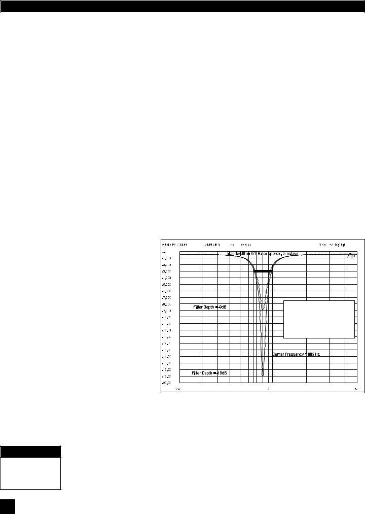
• FILTER WIDTH generally refers to the width (measured in octaves, or fractions thereof) of a filter, including graphic EQ filters, parametric filters, and FBX filters. More specifically, width is defined by determining the outer frequencies (surrounding the filter center point) that are altered
± 3 dB when the filter is imposed. This is shown in the diagram below:
In this example, the filter width is defined as approximately one-half octave, corresponding to the band of frequencies attenuated 3 dB or more when the filter is pulled down. In this example, the width is the same whether the
filter depth is -9 dB or -19 dB.
•CONSTANT Q filters are filterswhosewidthsremain
constant regardless of the amount of boost or attenu-
ation imposed by the filters. In other words, in the
above example, a Constant Q filter that was one half-octave wide would remain a half-octave wide regardless of the EQ slider
position. Some EQ units on the market are Con-
stant Q; others are Proportional Q, meaning the
filter gets wider as it gets
deeper. All Sabine products use Constant Q filters, to prevent affecting any more sound than necessary.
•FBX Setup Mode refers to Sabine’s unique, exceptionally fast method of placing FBX filters during sound system setup. Setup Mode is less “fussy” about analyzing the sound it hears and is more likely to regard audio signals over a minimum threshold as feedback. It’s also designed to allow feedback to occur at lower input levels, and, finally, it imposes a strong limiter on the feedback output as it occurs. The net result of all this black magic is that you are able to ring out feedback more
quickly, and at a much quieter level! You’ll know Setup Mode is engaged when the Setup LED (at the right of the front panel) is illuminated.
NOTE:MAKESURESetupModeISOFFWHENYOUUSETHEGraphi-Q2ORYOURAUDIOSIGNAL
QUALITY MAY SUFFER! (See Section 6.4.2.3 Setup Mode Cautions).
14
SECTION SIX: USING GRAPHI-Q2 CONTROLS
6.4.2. Front Panel Control of FBX filters
Note: Most of the front panel and GRQ-Remote control operation of the FBX section of the Graphi-Q2 is similar, except that the remote control replaces your fingers with a mouse. In addition, there are some controls offered only with GRQ-Remote software. These features are summarized in Section Eight.
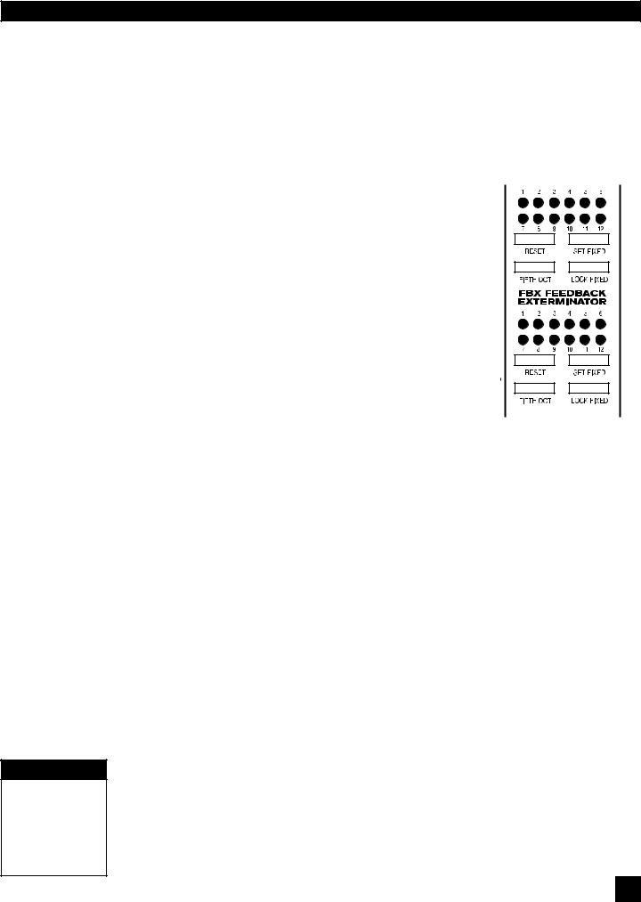
Controls for the patented FBX Feedback Exterminator are located immediately to the right of the HIGH and LOW CUT FILTERS.
6.4.2.1. FBX Filter LED Indicators
The 12 LEDs on the front panel Graphi-Q2 correspond to 12 available FBX filters. Each time an FBX filter sets, another LED will light. A blinking LED indicates which filter was
most recently set or made deeper (a filter may start at one depth and notch deeper at the same frequency as the system gain increases). The GraphiQ2 comes preset from the factory to a default setting of nine Fixed and three Dynamic filters. However, you may follow the instructions in STEP 5 below to reconfigure the setup to be any combination of Fixed and
Dynamic filters.
6.4.2.2. Eliminating Feedback with the Graphi-Q2 FBX Filters
IMPORTANT
Turbo Mode needs QUIET. No program, talking, music or loud room
noise!
Follow these steps to obtain the maximum gain before feedback, with minimal or no loss in the tonal quality of your program. The steps that follow are applicable to setting up a one-channel unit (GRQ3121). When using the GRQ3122, we recommend setting up one channel at a time by turning down the other channel of the mixer or power amplifier. If you are using both outputs of your GRQ3121, you may wish to turn down the power amp gain for whichever output is less likely to produce feedback. If both channels are equally feedback prone, leave the power amps turned up. This will allow you to set filters that are specific to each channel of your sound system.
STEP ONE: EQUIPMENT SETUP
Set up your sound system and position all the speakers and microphones you anticipate using. When possible, avoid placing microphones directly in front of speakers.
STEP TWO: TURN OFF NOISE GATES
If there is any equipment in the signal path that incorporates a noise gate function, you MUST DISENGAGE these noise gates prior to the setup procedure. You may reengage them upon setup conclusion.
STEP THREE: GAIN DOWN, TURN ON
Set the master volumes on your mixer to their lowest gain positions. Turn on the mixer, then the GraphiQ2, then any other accessories, and finally your power amplifier. Adjust the gain settings and balance for all your microphones, but keep your master mixer volume down.
STEP FOUR: RESET FILTERS
If there are FBX filters already set (indicated by illuminated LEDs), you should RESET these filters. (NOTE: For maximum FBX power, we recommend resetting filters every time you change or move your sound system.)
The Graphi-Q2 allows two stages of filter resetting. You may reset only the Dynamic filters, or you may elect to reset all (both Fixed and Dynamic).
•To RESET DYNAMIC FILTERS ONLY, press and hold the RESET button long enough for the Dynamic filter LEDs to flash three times, then release.
•To RESET ALL FILTERS, press and hold the RESET button for seven flashes of all the LEDs, then
release.
Note that resetting all filters automatically engages FBX Setup Mode, which will allow feedback to occur and be removed more readily, and at a lower volume. “Setup Mode on” will be indicated by the Setup LED (at the right of the front panel) illuminating.
NOTE:MAKESURESetup ModeISOFFWHENYOUUSETHEGraphi-Q2ORYOURAUDIOSIGNAL QUALITY MAY SUFFER! (See Section 6.4.2.3 Setup Mode Cautions)
NOTE: Setup steps continued on next page
15
B1-GRQ-2-OpGuide-v1-060519.pmd
SECTION SIX: USING GRAPHI-Q2 CONTROLS
IMPORTANT
Setup Mode needs QUIET.
No program, talking, music or loud room noise!
STEP FIVE: SET FIXED FILTERS (Optional)
If you want to change the factory default setting of nine Fixed and three Dynamic FBX filters, press and hold the SET FIXED button. The corresponding LEDs for all filters set to FIXED will come on, then all filter LEDs will flash, then each filter LED will begin to light in sequence. Continue to hold the button -- when the LED corresponding to the desired number of fixed filters lights, release the SET FIXED button. The number of fixed filters has now been set. All remaining filters will automatically default to Dynamic filters — unless you are setting filters with your computer. (See Section Eight)
STEP SIX: SET FBX FILTER WIDTH (Optional)
FBX filters default to a Constant Q width of one-tenth of an octave. Extensive Sabine research has shown this width to be an ideal setting, wide enough to remove feedback with very little or no effect upon the rest of the audio program. In some applications (for example, speech-only applications, where audio quality is not as demanding as in a music program), however, it may be advisable to use a wider filter for more robust feedback elimination.
The Graphi-Q2 allows you to mix filter widths between one-tenth and one-fifth octaves. You may set all filters to one width, or some filters to tenth-octave and some to fifth-octave. Width selection is controlled by the button marked “FIFTH OCT” directly below the RESET button. When this button is pushed and the LED is illuminated, any filters set after that point will be one-fifth octave wide. Pushing the button again, and switching off the LED, will make any additional filters one-tenth octave wide.
STEP SEVEN: RAISE MASTER GAIN
First, make sure your Graphi-Q2 is not set to bypass the FBX filters (check the Bypass button LED; it should be off). Then, make sure your power amplifier is turned up and your microphones are turned on. (Note: If you reset the FBX filters, your Graphi-Q2 will be in Setup Mode, as indicated by the front panel Setup LED. See the cautions below.) Slowly raise the master gain of your mixer until the first feedback begins. The FBX will quickly remove the feedback, by setting the first filter and lighting the first filter LED. Continue to raise the gain slowly. Try to avoid making two or more frequencies feed back at the same time, which sometimes happens if the gain is raised too quickly. As new frequencies feed back, new filters will be placed, as indicated by consecutive filter LEDs lighting up. (Note: sometimes the same frequency will feed back a second time, and an earlier filter will notch more deeply. When this happens, the original LED indicating this frequency will blink, showing it to be the most recently active filter.) Repeat this procedure until one of two things happens:
1.All of the Fixed filters and at least the first Dynamic filter are set. This will automatically turn Setup Mode off (LED will turn off to indicate this), or...
2.You’ve set as many filters as you need or want, even though you haven’t used them all. Press LOCK FIXED to prevent any more Fixed filters from setting, or any of the set Fixed filters from notching more deeply. Pressing LOCK FIXED also exits Setup Mode. If you wish to allow unused Fixed filters to set or allow deepening of Fixed filters press the Lock Fixed button again.
NOTE: While Setup Mode is operating, the compressor LEDs may indicate compressor activity. This is normalandwillnotaffectcompressoroperationwhenSetupisnotengaged.WhenSetupModeautomatically turns off, you’ll be treated to a brief LED light show. The filter LEDs will light in sequence back and forth to indicate that you are exiting Setup Mode -- stop raising gain! Because Setup limits the volume of feedback as it occurs during setup, feedback volume may briefly increase when exiting Setup The dancing LED display is designed to caution you to monitor your master gain setting while coming out of Setup.
6.4.2.3. Setup Mode Cautions.
IMPORTANT
Setup Mode OFF
During
Performance
16
SetupModeisdesignedtoallowfastandquietfeedbackeliminationduringsetup.SetupModeshouldONLY be used for pre-performance setup. DO NOT USE Setup Mode DURING A PERFORMANCE! This will producedistortedaudioandsetfiltersonmusicoraudioprogram.SetupModealsomaynotworkwell during setup in a very noisy environment. To speed up feedback elimination, Setup relaxes its criteria for distinguishing“good”audiofromfeedbackandplacesfiltersmorereadily. Iftheenvironmentisnoisy,there is a greater likelihood of placing a filter on audio that is not feedback. When in doubt, turn Setup off by pressing the Lock Fixed button, then press Lock Fixed one more time (to ready the FBX Fixed filters) and raise your system gain as described in Step Seven above. This will still eliminate feedback very quickly, though not as quickly as Setup Mode, and without reducing the volume of the feedback before it is filtered out. You’ll know if Setup is on by the LED indicator on the Graphi-Q2 front panel.
Whether or not SetupMode is used, the end result of setting up FBX filters should be identical. Your sound system will have clearer, louder, feedback-free sound.
SECTION SIX: USING GRAPHI-Q2 CONTROLS
6.4.3. Adjustments Available Only with Remote Control
In addition to FBX, graphic, and high and low cut filters, your Graphi-Q2 can provide fully programmable parametric filters. These filters are accessible only through GRQ-Remote software. Each channel of your Graphi-Q2 can have up to 12 total filters, which can be configured as any combination of parametric, fixed FBX, or dynamic FBX filters. See Section Eight for a complete look at GRQ Remote Control Software.
6.5. COMPRESSOR/LIMITER CONTROLS
6.5.1. Front Panel Control
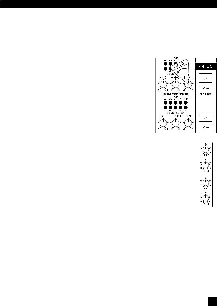
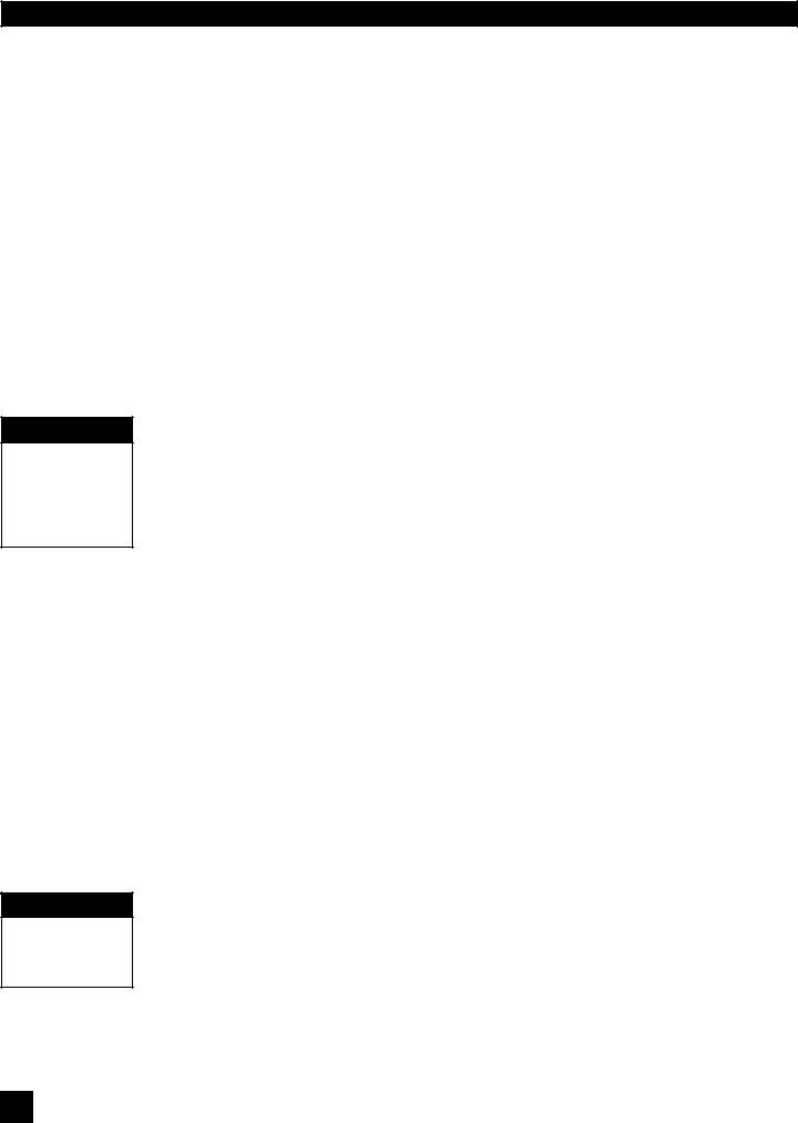
COMPRESSOR controls are located immediately to the right of the FBX controls. Front panel controls consist of standard RATIO, THRESHOLD, and GAIN makeup knobs, and two horizontal LED ladders showing channel input gain on the top, and compressor gain reduction on the bottom row.
TECH TIP |
RATIO ranges from 1:1 to infinity: 1 (limiting). |
|
|
|
|
|
|||
|
|
|||
Unity Gain |
The input level THRESHOLD, at which compression is engaged, can be |
|
|
|
Set Gain to 12:00 |
adjusted from -30 dBV to + 31.5 dBV. |
|
|
|
The output gain of the compressor can be increased or decreased by |
|
|
||
(straight up) for |
|
|
||
NOTE: Image shows |
||||
unity gain. |
12 dB (this will also serve as the control for the overall output level of |
|||
settings for bypassing |
||||
|
the box). |
|||
|
Compressor/Limiter. |
|||
|
||||
Compressor KNEE, ATTACK, and RELEASE settings can only be set using
the Remote Control Software, and will default to the last settings programmed. (In addition, the remote software will allow setting of a separate limiter threshold.) The factory default settings are attack = 15 mSec, release = 400 mSec, and knee = 20. These will remain in place until they are reprogrammed using the software (see Section 9.5.2 for detailed information on Compressor/Limiters and Section 8.2.6 for using the Graphi-Q2 Remote Control Software Compressor/Limiter control).
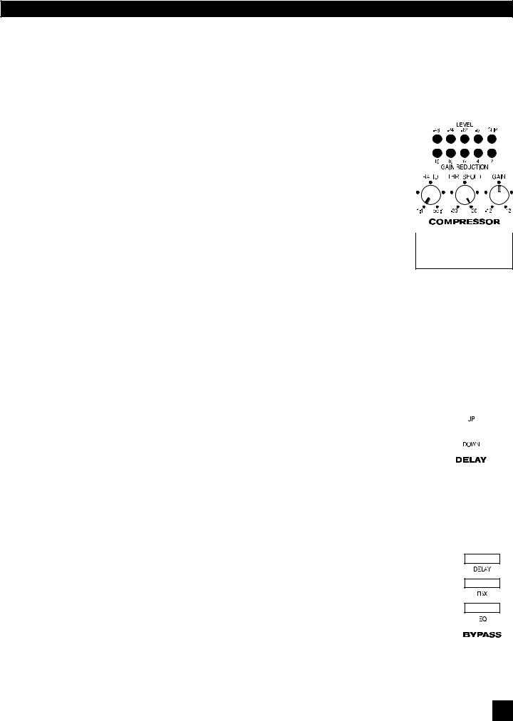
6.6. DIGITAL DELAY CONTROLS
6.6.1. Front Panel Control
DIGITAL DELAY controls are located to the right of the COMPRESSOR controls. |
|
|
|
|
1.38 |
|
|
You may delay the output of the Graphi-Q2 audio signal by up to 999.96 mSec |
|
|
|
|
|
|
|
(essentially one second) by using the up/down increment buttons just below the |
|
|
|
display showing the amount of delay in mSec. Delay adjustments may be made |
|
|
|
|
|
||
with 20-microsecond precision. |
|
|
|
For the GRQ3121 model, the digital delay adjustments from the front panel will |
|
|
|
|
|
||
affect ONLY the Output B signal. Output A will remain undelayed. You may of |
|
|
|
course alter the delay setting for either output using the GRQ Remote Software |
|
|
|
(see Section Eight). Note: For a complete discussion on using delays in sound |
|
|
|
systems (and we mean complete), see Section 9.4. |
|
|
|
When the Graphi-Q2 is first turned on, the firmware version will display briefly within the Digital Delay LED screen. See Section 6.2.3 for how Tweek-n-Peek uses the Digital Delay LED.
6.7.BYPASS
6.7.1.Front Panel Control
BYPASS controls are located at the far right of the Graphi-Q2 front panel. Separate push button controls allow independent bypass switching for graphic EQ, FBX, and digital delay settings. For two-channel Graphi-Q2s, separate bypass controls are available for each channel as well. When any feature is bypassed, the LED within the switch will illuminate.
Turning off power to the Graphi-Q2 will place the entire unit in hardwire bypass. Please note that a sudden bypass of FBX filters may result in a sudden burst of no-longer-filtered feedback. It ain’t pretty when this happens, so proceed cautiously.
17
B1-GRQ-2-OpGuide-v1-060519.pmd
 Loading...