


O p e r a t i n g
with
SMARTFILTERS
Contents
SECTION one — Front & Back Panels |
2 |
1.1. FBX2420 Front Panel Controls & LED Indicators |
2 |
1.2. FBX2420 Back Panel Controls & Connections |
2 |
SECTION two — APPLICATIONS |
3 |
2.1. FBX Setup for Monitors |
3 |
2.2. FBX Setup for Entire Mix |
3 |
2.3. FBX Setup for Single Insert Point |
3 |
2.4. FBX Setup for Insert Send & Return |
3 |
SECTION THREE — ENGINEERING SPECIFICATIONS |
3 |
SECTION FOUR — OPERATING INSTRUCTIONS |
4 |
4.1. Before You Begin |
4 |
4.2. How To Operate your FBX1220 / FBX2420 |
5 |
SECTION FIVE — How to use FBX Features |
6 |
5.1. Input / Output Level Switches |
6 |
5.2. FBX Filter Control |
6 |
5.3. Important Operating Considerations |
6 |
SECTION SIX — TROUBLESHOOTING TIPS |
7 |
SECTION seven — FBX Theory & Practice |
8 |
7.1. Introduction to FBX |
8 |
7.2. The Advantages of FBX Filters |
8 |
7.3. Parametric Filters and FBX |
9 |
7.4. Who Benefits from FBX? |
9 |
SECTION EIGHT — Cautions & Warranty |
10 |
Quick Start Setup on back page
SECTION one — Front & Back Panels
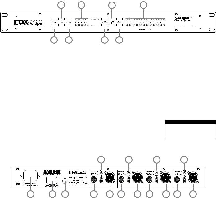
1.1. FBX2420 Front Panel Controls & LED Indicators
2 |
4 |
6 |
8 |
Note: FBX1220 front and back panels use the same controls and input/output configuration
1 |
3 |
5 |
7 |
1.SETUP
Press and hold this button to begin the FBX setup mode. Filter
LEDs (light emitting diodes) will flash 5 times and the SETUP LED will begin to flash. You are now ready to set FBX filters.
2.READY
The READY LED lights when the automatic FBX setup process has completed, or the READY button has been pressed. This indicates your unit is ready for operation. The total number of filters available for feedback filtering is 12; in the factory default setting, your unit will automatically enter READY mode when the tenth filter is set.Alternatively, you may enter READY status with fewer Fixed FBX filters in place, simply by pressing the READY button at any time. Press READY again to lock the Fixed filters.
3.BYPASS
Bypass mode takes the unit out of the signal path so that it will have no effect on the program. In active mode, the unit controls feedback automatically. The red BYPASS LED lights when the unit is in bypass mode.
4.SIGNAL LEVEL
The LED ladder indicates the signal strength relative to the FBX's input clip level.
5.RESET DYNAMICS & DYNAMIC FILTER TIMER
Press and hold this button until the Dynamic filter flash and LEDs go off to reset all Dynamic filters. See Section 5.2.4. for enabling and setting the Dynamic Filter Timer.
6.NUMBER FIXED
Set the number of available fixed filters by pressing the NUMBER FIXED button (6) until the LEDs stop flashing, then release it. The LEDs (8) will begin to light in sequence. When the LED corresponding to the desired number of fixed filters lights, press the Number Fixed button to register your selection.
7.FIFTH OCTAVE
Press the button at any time to select wider filters for any new filters to be set. It is possible to have both 1/5 and 1/10 octave constant "Q" filters active in one channel simultaneously.
8.FILTER STAGE ACTIVITY
When one of the unit’s filters is activated, the corresponding LED lights. A blinking LED
indicates the filter that was most recently activated.
1.2. FBX2420 Back Panel Controls & Connections
13 |
13 |
13 |
13 |
9 |
11 |
10 |
12 |
14 |
12 |
14 |
15 |
16 |
15 |
16 |
9.A/C Power Input
The FBX1220 & FBX2420 Series is factory configured to operate at 230 VAC. Using the wrong input voltage may cause permanent damage to the unit and will void the warranty.
10.Fuse
This equipment is fitted with an IEC power inlet incorporating a built-in fuse holder. To change the fuses in this socket:
1.Disconnect the power cord from the unit.
2.Pull out the fuse holder and remove the old fuse.
3.Install a new fuse into the holder. Replace only with one of the following fuses:
• 230 VAC: 0.1 A, 10 W, 0.160 A SB fuse
4.Refit the fuse cover.
11. Power Switch
Previous settings retained during power-off.
12. Quarter-inch Output
TRS balanced or TS Unbalanced output .
13. Input/Output Level Switches
Set to match your desired Input/Output level configurations.
For unity gain set both switches to the same postion.
14. XLR Output
XLR balanced output.
15. Quarter-inch Input
TRS balanced or TS unbalanced input.
16. XLR Input
XLR balanced input.
2

SECTION two — APPLICATIONS |
Monitor Mix 1 |
|
|
2.1. FBX Setup for Monitors |
Monitor Mix 2 |
Ch. B |
Ch. A |
|
|||
|
|
IN |
IN |
|
Ch. B |
Ch. A |
|
|
OUT |
OUT |
|
2.2. FBX Setup for Entire Mix |
Right Main Send |
|
|
|
Left Main Send |
Ch. B |
Ch. A |
|
|
IN |
IN |
|
All other Signal |
|
|
|
Processing |
|
|
|
Ch. B |
Ch. A |
|
|
OUT |
OUT |
|
2.3. FBX Setup for Single Insert Point
|
|
IMPORTANT NOTE |
|
|
|
• Mixing balanced and unbal- |
|
Ch. 1 |
Ch. 2 |
anced connections may result |
|
in a 6 dB loss of gain. |
|||
|
|
||
< Low Z > |
|
||
< High Z > |
|
||
< |
Insert > |
TRS Connector |
|
|
TRS Connector |
Y Insert Cords (TRS to TS + TS) |
|
TS "Y" Connector
|
|
|
|
|
|
|
|
|
|
|
|
|
|
|
Ch. B OUT Ch. A OUT Ch. B IN |
Ch. A IN |
||||
|
||||||
|
||||||
TS "Y" Connector
2.4. FBX Setup for Insert Send & Return
Ch. 1
ReturnInsert> 

 < InsertSend
Ch. 2
ReturnInsert> 

 < InsertSend
TS or TRS Connectors |
|
Ch. A OUT |
Ch. A IN |
IIMPORTANT NOTE |
|
• Use a ¼--iinch TRS pllug fforr |
|
ballancedsends/inserts.. |
|
Ch. B OUT |
Ch. B IN |
• Use a ¼--iinch TS pllug fforr unballancedsends/inserts..
•Miixiing ballanced and unball-- ancedconnectionsmayrresult iina6dBlossofofgain..Refer to section 5.2.
TS or TRS Connectors
SECTION THREE — ENGINEERING SPECIFICATIONS
Filters
•12 independent digital notch filters per channel, controlled automatically from 40 Hz to 20 KHz.
•Filterwidth:user-controllable-either 1/10 or 1/5 octave*, constant "Q"
•Resolution: 1 Hz
•Time required to find and eliminate feedback: 0.4 seconds, typical @ 1 KHz
•Number of Dynamic vs. Fixed filters per channel: user selectable. Last configuration stored in
memory.
*Below approximately 200 Hz the feedback filters become slightly wider to increase the feedback and rumble capture speed at these low frequencies.
Input/output**
•Input/Output Maximum Signal Levels: Balanced +27dBV peak, unbalanced +21 dBV peak
•Output Drive: Unit will perform as specified driving a load >600 Ohms
•Input Impedance: Balanced or unbalanced >40K Ohms, PIN 2 high
•Output Impedance: Balanced or unbalanced150Ohmsnominal,PIN 2 high
•Bypass: True power off bypass
•Headroom: +23 dB peak @ 4 dBV
nominal input, balanced
•I/O Connectors: XLR-3 and 1/4" TRS
PERFORMANCE***
•Frequency response: 20 Hz – 20 KHz +/- 0.3 dB
•Gain matching: +/- 0.2 dB
•Spectral Variation: + .25 dB, 20 Hz to 20 KHz
•SNR - Dynamic Range: >100 dB
•THD: .005% at 1 KHz
<0.01% 20 Hz – 10 KHz
<0.025% 10 KHz – 20 KHz
•Dynamic Range: >105 dB
Tests performed using an Audio Precision System One model 322 or equal.
POWER INPUT
• 230 VAC: 200 – 240 VAC 50/60 Hz
FUSE
• 230 VAC, 0.1 A, 10 W, 0.160 A SB
fuse |
Inc. |
|
DIMENSIONS |
||
Sabine, |
||
• 1-U rack mount; 19 x 1.75 x 6.25 in. |
||
x 15.9 cm nominal |
||
nominal(rackmountable);48.3x4.5 |
2008 |
|
WEIGHT |
||
• 8.0 lbs. (3.6 kg) nominal |
© |
|
|
LIT-FBX1220-1224-OP-EN-080208.pmd - ks 3
SECTION FOUR — OPERATING INSTRUCTIONS
4.1. Before You Begin
These instructions apply to both the FBX1220 and the FBX2420. The 2420 is a dual-mono version of the 1220. Your FBX Feedback Exterminator will improve any sound reinforcement system. The instructions presume that you are familiar with the fundamentals of sound reinforcement.
4.1.1. Where the FBX fits in your sound system:
The most common patch point is between the output of the mixer and the input of a power amp. In this position, the FBX can sense and eliminate feedback occurring in any channel of the mixer. An even better solution is on a mixer insert point for a single channel, or a subgroup (see application diagrams in Section Two — Applications). This targets the feedback control to the mics that need it.
Note: If you’re using a mixer with unbalanced 1/4" outputs, you must use standard unbalanced cables and connectors when connecting it to the FBX. Similarly, if your mixer is wired for balanced 1/4" Tip-Ring-Sleeve (TRS) outputs, you must use that type of connector. If you don’t, you may experience a loss of gain (up to 6 dB) when using the FBX. This can occur if either side of the balanced output is grounded at any point (or when mixing balanced and unbalanced inputs and outputs).
4.1.2. A note about graphic equalizers:
The FBX is designed to replace the graphic equalizer’s function for eliminating feedback. In many applications, such as churches, auditoriums or small acoustic ensembles, the mixing board provides all the tonal control that is necessary. The FBX can replace the graphic EQ altogether in some applications; however, a graphic equalizer may be beneficial to shape a system's total performance. If you do want to use an equalizer, place the FBX after the EQ in the signal path. Use the EQ’s controls to shape the tonal response of the sound system, but DO NOT NOTCH FOR FEEDBACK.
4.1.3. Understanding FIXED and DYNAMIC filters
Before operating the FBX, you need to understand the two types of FBX filters: FIXED and DYNAMIC. FIXED FILTERS retain their frequency center-points until the unit is reset by the user. The system’s gain before feedback is limited primarily by the number of fixed filters; i.e., increasing the number of fixed filters increases the system’s gain before feedback. In addition, you can LOCK the fixed filters so they do not get any deeper. Locked fixed filters are no longer adaptive. The FBX's DYNAMIC FILTERS control intermittent feedback that comes and goes throughout the program.They are continually reset automatically to different frequencies as new feedback occurs during the program. For most applications, the optimal setting is nine FIXED and three DYNAMIC FILTERS. This is the factory default.
4.1.4. Setup & Ready
Your FBX Feedback Exterminator is either in Setup, Ready, or Bypass mode.
Setup Mode: It’s quick and quiet, but use this mode for setup only – do not use the FBX for your program while in Setup mode. Think of Setup mode as your key to achieving one of the main benefits of the FBX: getting more gain before feedback. In Setup mode you will be raising the gain of your system so the FBX can place transparent filters (Fixed Filters) that will allow you to get all the gain you need for a loud and clear show. In Setup the FBX is very sensitive so do not talk into the mics during setup, and try to keep room noise to a minimum. If the room is noisy, then go into Ready mode and raise your gain while the fixed filters are still unlocked (flashing Ready LED).
Ready Mode: Let the show begin. Your fixed filters are eliminating feedback and giving you extra gain, and your dynamic filters are ready to jump on any new feedback during the show. In this mode your fixed filters are either locked (red LEDs) or unlocked (amber LEDs). We recommend locking your fixed filters for the show. But if you don’t have time for the Setup mode, or if the room is just too noisy during setup, then you can start off by unlocking the fixed filters. Leaving the fixed filters unlocked allows them to get deeper if needed, which can be handy if you need to get more gain before feedback. But once your system stabilizes we recommend you lock the fixed filters for the duration of the show!
4
 Loading...