


CONTENTS
SECTION 1 Introduction .......................................................... 1
SECTION 2 Controls & instruments ........................................ 9
SECTION 3 Driving & operating ............................................. 59
SECTION 4 Owner maintenance ............................................. 97
SECTION 5 General data ......................................................... 139
SECTION 6 Parts & accessories............................................... 149
SECTION 7 Off-road driving.................................................... 155
Index ..................................................................... 167
As part ofLand Rover environmental policy,this publication isprinted on paper madefrom
elemental chlorine free pulp.
Publication No. LRL 0156NAS
1997 Rover Group Limited


SECTION 1
Introduction
OWNER’S HANDBOOK
This handbook coversthe currentversion of
the Land Rover Discovery and,together with
the Passport to Service, providesall the
information you need to derivemaximum
pleasure from owningand drivingyour new
vehicle.
For your convenience,the handbookis divided
into sections, eachdealing witha different
aspect of driving or caringfor thevehicle. The
sections are listedon thecontents pageand
you will find it worthwhileto takea littletime
to readeach one, and get to know your
Discoveryas soonas youpossibly can. The
more you understand before youdrive, the
greater the satisfactiononce youare seated
behind the steering wheel.
Land Rover operates a policy of constantproduct
improvement and therefore reserves the right to change
specifications without notice at any time. Whilst every effort
is made to ensure complete accuracy of theinformationin
this handbook, no liabilities for inaccuracies orthe
consequences thereof can be accepted by the
manufacturer, Land Rover North America Inc.
All rights reserved. No part of this publicationmaybe
reproduced, stored in a retrieval system or transmitted,in
any form, electronic, mechanical, photocopying, recording,
or other means without prior written permission from Land
Rover.
Section Contents Page
Reporting safety defects 1..............................
Safety warnings 3...........................................
Passport to Service 3......................................
Information labels 4........................................
Vehicle identification number 6.......................
Anti-theft precautions 7..................................
Breakdown safety code 7................................
Reporting safety defects
If youbelieve that yourvehicle hasa defect
which could cause a crash,or couldcause
injury or death, you shouldimmediately
inform the NationalHighway TrafficSafety
Administration (NHTSA) inaddition to
notifying Land Rover North AmericaInc.
If NHTSAreceives similarcomplaints, it may
open an investigationand ifit findsthat a
safety defect existsin agroup ofvehicles, it
may order a recall andremedy campaign.
However, NHTSA cannotbecome involvedin
individual problems betweenyou, yourDealer
or Land Rover North America.
To contactNHTSA, you may callthe Auto
Safety hotline tollfree at1-800-424-9393 (or
202-366-0123 in Washington, D.C. area)or
write to: NHTSA, U.S. Departmentof
Transportation, Washington, DC20590. You
can also obtain other informationabout motor
vehicle safety fromthe hotline.
1

2

Introduction
PASSPORT TO SERVICE
The Passport to Service includedin your
literature pack, containsimportant vehicle
identification information, detailsof your
entitlement under the terms ofthe LandRover
warranty, as wellas usefulconsumer advice.
Most important of all, however,is thesection
on maintenance.This outlinesthe servicing
requirements for yourDiscovery, as well as
incorporating the servicerecord slips, which
the Dealer shouldsign andstamp tocertify
that the routine services havebeen carried out
at the recommended intervals.
WARNING
Safety warnings are included in this
handbook. These indicate either a procedure
which must be followed precisely, or
information that should be considered with
great care in order to avoid the possibility of
personal injury or serious damage to the
vehicle.
WARNING LABELS ATTACHED TO THE
VEHICLE
Warning labels attached to your
vehicle bearing this symbol
mean: DONOT touch or adjust
components until you have read the relevant
instructions in the handbook.
Warning labels showing this
symbol indicate that the ignition
system utilises very high
voltages. DO NOT touch any ignition
components while the starter switch is
turned on!
WARNING
The Discoveryhas a higher ground
clearance and hence a higher centre of
gravity than ordinary passenger carsto
enable thevehicle to perform in a wide
variety of off-road applications. An
advantage of the higher ground clearance is
a betterview of the road, allowing you to
anticipate problems. Discovery is not
designed for cornering at the same speed as
conventional passenger cars any more than
a lowslung sports car is designed to
perform satisfactorily under off-road
conditions. As with other vehicles of this
type, failure to operate the Discovery
correctly, may result in loss of control,or
vehicle rollover.
3

Introduction
INFORMATION LABELS FIXED TO THE VEHICLE
A. BATTERY WARNING LABEL
B. THIS PLUG MUST NOT BE REMOVED
WHEN ENGINE IS HOT
C. AIR CONDITIONINGLABEL
D. KEEP CLEAROF ROTATINGPARTS
E. JACKING INFORMATION LABEL
F. ANTIFREEZE - DO NOT DRAIN
G. REWAX AFTERSTEAM CLEANING
NOTE: Variouslabels are fixedto thevehicle
to drawyour attention to specificsafety and
emission information. Thisillustration is for
general guidance onlyas theposition of
components and the extent of labels andother
visual warnings onthe vehiclecould vary from
model to model.
4

Introduction
Details of the vehicle height,both withand
without an open sunroof and information on
the vehicle’s handlingcharacteristicsare
printed on the underside ofthe driverssun
visor.
On vehicles fittedwith AirbagSupplementary
Restraint Systems (SRS),remember to take
careful note of warning labelsand other
information attached toboth sunvisors, orto
other parts of the vehicle.
I. WARNING!
Manufactured with
1.1.1.- TRICHLORETHANE substancewhich
harms public healthand environmentby
destroying ozone in the upperatmosphere.
J. Transfer gearbox
Important - transfer gearbox information.
To changetransfer box ratio, reducespeed
to below5 mph (8 km/hour), select auto
’N’, move high/low lever rapidlyto required
position, select autogear. Alternatively,
stop vehicle and make selectionas above.
For maximum engine braking, selectauto
’1’, keep engine running.
K. Jacking labels
DO NOT get under a vehicle supportedonly
by the jack: use vehiclesupport stands.
5

Introduction
VEHICLE IDENTIFICATION NUMBER (VIN)
If youneed to communicate with aLand
Rover dealer, youmay beasked to quote the
Vehicle Identification Number(VIN).
The VIN and other informationconcerning the
vehicle can befound on the certificationlabel
affixed to the lock faceof thefront left-hand
door, where shown (this VINshould match
the VIN recorded in thePassport toService
book).
In addition,the FederalVIN plateis mounted
to thevehicle body in such aposition thatit is
visible from the outside, throughthe bottom
right corner of the windscreen.
WARNING
DO NOT exceed gross weight or axle loads
described on the vehicle certification/
identification label.
6

Introduction
ANTI-THEFT PRECAUTIONS
While it may be impossibleto deterthe
’professional’car thief,the majorityof thefts
are carried outby unskilledopportunists.
Therefore, take vehiclesecurity very seriously
and ALWAYS adopt this simple’five point’
drill whenever youleave yourvehicle - even
for just a few minutes:
• Fully close allthe windows(and the
sunroof).
• Remove your valuablebelongings (or hide
them out of sight).
• Remove the starterkey.
• Engage the steering lock (byturning the
wheel until it locks.
• Lock all the doors and turn on the alarm.
Thieves are attractedto ’vulnerable’vehicles.
Even if you have followedthe ’fivepoint’ drill,
there is stillmuch youcan doto makeyour
vehicle a lessinviting target.
BE SAFENOT SORRY!
• Park where your vehicle caneasily be seen
by householders and passers-by.
• At night, park in well lit areasand avoid
deserted or dimlylit sidestreets.
• At home, if you have a garage,use it- and
NEVER leave the keys inthe vehicle.
• Do not keep important vehicledocuments
(or spare keys)in thevehicle - these are a
real bonus for the thief.
IMPORTANT INFORMATION
Remember the breakdown safety code
If abreakdown occurs whiletravelling:-
• Wherever possible, consistentwith
road safety and traffic conditions,
the vehicle shouldbe movedoff the
main thoroughfare onto the shoulder
as far as possible. Ifbreakdown
occurs on a freeway, pullwell over
to theinside of the hard shoulder.
• Switch on hazard lights.
• If possible,position a warning
triangle or flashingamber light,at an
appropriate distance fromthe
vehicle to warn other trafficof the
breakdown (note the legal
requirements of someareas).
• Consider evacuating passengers
through the right hand doors away
from the road as a precaution in
case your Discoveryis struck by
another vehicle.
7

8

SECTION 2
Controls & instruments
In thissection of the handbook you willfind
descriptions of the controls andinstruments
on yourDiscovery.
For your own safety, itis mostimportant to
read this sectionfully andto gaina thorough
understanding of all the controlsbefore
driving.
Section Contents Page
Controls 11.....................................................
Locks & alarm 12...........................................
Seats 18.........................................................
Seat belts 24...................................................
SRS/Airbag 29................................................
Steering column 33........................................
Exterior mirrors 34.........................................
Instruments 35...............................................
Warning lights 37...........................................
Lights & indicators 40....................................
Wipers & washers 40.....................................
Switches 43....................................................
Windows 45...................................................
Sunroof 46.....................................................
Heating & ventilation 47.................................
Air conditioning 51.........................................
Interior equipment 53.....................................
Loadspace cover 57........................................
Rear step 58...................................................
9

10

Controls
1. Instrument panel illuminationcontrol
2. LH switch panel
3. Driver’sSRS/airbag
4. Instrument and warning light pack
5. Cruise control switches
6. RH switch panel
7. Clock
8. Hazard warning lightswitch
9. Radio/cassetteplayer
10.Heater and air conditioning controls
11.Coin tray
12.Glovebox
13.Passenger’s SRS/airbag
14.Electric mirror adjustmentcontrol
15.Steering column height adjuster
16.Front foglight switch
17.Cruise control masterswitch
18.Transfer gear lever
19.Parking brake
20.Heated front seat switches
21.Electric window switches
22.Main gearboxlever orselector
23.Cigar lighter
24.Cup holder
25.Ashtray
NOTE: Theprecise specification andlocation ofcontrols may varyfrom modelto modelwithin the
vehicle range (automatictransmission illustrated above).
11

Locks & alarm
ALARM SYSTEM
Your vehicle isfitted witha sophisticated
electronic anti-theft alarmsystem. In order to
ensure maximum security,you arestrongly
advised to gain a fullunderstanding ofthe
alarm system bythoroughly readingthis
section of the handbook.
LOCKING THE VEHICLE AND ARMING THE
ALARM
Before locking the vehicle andarming the
alarm, ensure alldoors, windows,sunroof and
hood aresecurely closed.
Locking with the handset
Within range of the vehiclebriefly press the
lock button (PADLOCK SYMBOL) on the
handset. If the doors lockcorrectly, thehazard
warning lights willflash threetimes and the
alarm indicator (locatedin theinstrument
pack) will startto flash.
Each time the vehicle islocked using the
handset, a coded signal istransmitted to a
receiverinside thevehicle, which activatesthe
following security features.
• The central door locking system(all the
door locks are activated).
• The alarm (protectsthe doorsand hood).
Once armed, the alarm willsound ifthe hood,
or any door is opened.
12

Locks & alarm
Unlocking with the handset
Within range of the vehicle,briefly press the
PLAIN button on the handset; the hazard
warning lights flashonce, thealarm is
disarmed immediately andthe doorsunlock.
NOTE: Theinterior lights illuminatewhen the
alarm system isdisarmed.
If thehandset fails to unlock thevehicle, use
the key and re-synchronise thehandset (see
item 6 under ’Handset battery’).
If thealarm sounds
To silencethe alarm,press eitherhandset
button, oroperate the door locks usingthe
key. If the alarm isnot silenced,it will sound
for approximately 30seconds before
switching itself off and canbe triggeredup to
three times in total beforeneeding tobe reset.
Anti-theft alarm indicator light
After locking, the RED indicatorlight on the
instrument panel willflash rapidlywhile the
alarm system isarming itself.
After 10 seconds, the indicatorlight adjuststo
a slower frequencyand continuesflashing as
an anti-theft deterrent,until thealarm is
disarmed.
NOTE: Thehandset complieswith part 15 of
the FCC rules. Operation issubject to the
following two conditions:
1. This device maynot causeharmful
interference.
2. This device must accept anyinterference
received, including interferencethat may
cause undesired operation.This appliesto
both alarmreceivers andhandset
transmitter.
CAUTION: Any changesor modificationsto
the transmitter not expressly approvedby the
manufacturer could voidthe user’sauthority
to operatethe equipment.
13

Locks & alarm
HANDSET BATTERY
The handset battery should lastfor
approximatelythree years,dependent upon
use. When the battery needsreplacing, it will
be apparent from the followingsymptoms:
• The handset will only workevery other
operation.
• The hazard warning lights willnot flashon
when the alarm is disarmed.
Always fit a Panasonic CR2032
replacement battery (availablefrom a Land
Rover dealer) andadopt thefollowing
replacement procedure:
1. Carefully open the handset. Startfrom the
keyring end using a coinor small
screwdriver.Avoid damagingthe seal
between the two halves ofthe caseand
DO NOT allow dirt ormoisture toget
inside the handset.
2. Slide the battery out of its clip,taking care
to avoidtouching the circuit boardor the
contact surfaces ofthe clip.
3. Press and hold one of the buttons for at
least five seconds(this willdrain any
residual power fromthe handset).
4. Fit the new battery, ensuringthat correct
polarity is maintained(positive (’+’) side
facing up). Finger marks willadversely
affect battery life;if possible,avoid
touching the flat surfaces ofthe battery
and wipe them clean beforefitting.
5. Reassemblethe twohalves ofthe handset.
6. Unlock the vehicleusing thekey, then
operate the lock button of the handsetat
least four times.
The handset is now readyfor use.
NOTE: Thehandset containsdelicate
electronic circuits andmust beprotected from
impact and water damage, hightemperatures
and humidity, direct sunlight andthe effects
of solvents,waxes andabrasive cleaners.
14

Locks & alarm
ALARM OR HANDSET DIFFICULTIES
Alarm goes off unexpectedly. Ensure all windows, doors, hoodand sunroof
are closed.
Vehicle will not start. Press unlock button on handset. If it still will
not start,consult your Land Roverdealer.
Hazard lights don’tflash whenalarm is
armed.
Doors unlock and hazard lightsstart to
flash when vehicleis inmotion.
Within range of the vehicle,the handset
appears to malfunction.
Ensure all windows, doors, hoodand sunroof
are closed.
The inertia switchhas beentriggered. Stop the
vehicle and turn the starterswitch off and on
again. Central door locking willbe inhibited for
5 minutes.If fault continues, consultyour Land
Rover dealer.
The handset may have lostsynchronisation.
Press the lock button on the handsetfour times
whilst within range of thevehicle.
15

Locks & alarm
KEY AND HANDSET NUMBERS
You havebeen supplied with twoidentical
remote control handsetsand apair ofidentical
keys which operateall locks,including the
rear door and petrol flap.
The key number is stampedon atag attached
to thekey ring. Checkthat thekey numberhas
been entered in the spaceprovided onyour
Security Information card.
If thekey or handset is lost,contact aLand
Rover dealer, whocan supplya replacement
or additional keysand handsets.
WARNING
Keep theSecurity Information card, key tag,
spare key and handset in a safe place - NOT
IN THE VEHICLE!
LOCKING USING THE KEY
Front doors
Turn the key towards the front ofthe vehicle
to lockand towards the rearto unlock.
Locking the doors without activating the
alarm
By turning the key to the lockposition and
then holding it in that position forat leastfive
seconds, the doors will belocked butthe
alarm will remaininactive.
Central locking
By turning the key in the driver’sdoor, or
operating the lockingbutton onthe driver’s
door (from inside the vehicle),all the door
locks can be operated simultaneously.
Door sill locking buttons
From inside the vehicle, eachdoor can be
individuallylocked bydepressing the
appropriate button.
NOTE: Asa precautionagainst accidentally
locking your keysinside, itis not possible to
use the locking buttons to lock thefront doors
when you are leaving thevehicle - THE KEY
OR HANDSET MUST BE USED!
NOTE: Turningthe keyalso arms and
disarms the anti-theftalarm.
Rear door
Turn the key towards the right sideof the
vehicle to lockand tothe leftto unlock.
16

Locks & alarm
Move the locking levers tothe ’ON’position
(as illustrations) toengage.
With the child locks engaged,neither the rear
doors nor the tailgate canbe openedfrom
inside the vehicle,thereby avoidingthe risk of
a door being opened accidentallywhile the
vehicle is moving.
NEVER leave unsupervised children in your
vehicle.
Door locking cut-off switch
An inertiaswitch, operationalonly withthe
starter switch inposition ’II’,prevents the
doors from centrallylocking (orif the doors
are locked, willunlock them)in the event of an
accident or sudden impact.
When the inertia switch operates,the central
door locking is inhibited andhazards flashfor
a minimum of 30 seconds or untilthe system
is reset by turning thestarter switchon and
off, twice.
Child locks
WARNING
17

Seats
MANUALLY OPERATED FRONT SEATS
Forward/backward movement
Lift the bar to slide the seatforward orback.
Ensure the seat is lockedin positionbefore
driving.
WARNING
To avoidthe risk of loss of control and
personal injury, DO NOT adjust the driver’s
seat while the vehicle is in motion.
Lumbar support (1)
Rotate the handwheel to increaseor decrease
support to the lumbar regionof theback.
Backrest movement (2)
Rotate the handwheel to adjustthe backrestto
the required angle.
WARNING
DO NOT allow occupants to travel with the
seat backs reclined steeply rearwards.
Optimum benefit is obtained from the seat
belt, with the seat back angle set to 15
degrees from the upright (vertical) position.
18

POWER OPERATED FRONT SEATS
(if fitted)
The seat adjustment controls aresituated on
the centre consoleadjacent tothe seat
bolsters. Adjustment isonly possiblewhen
the starter switchis turnedto positions’I’ or
’II’, or with a front door open when the starter
switch is in position ’0’.
The following functions are available:
Seats
Seat forward/rearward
Push and hold the switch forwards or
backwards, to move the seatto thedesired
position.
WARNING
To avoidthe risk of loss of control, never
adjust the driver’s seat or seatback while
the vehicleis in motion.
DO NOT allow occupants to travel with the
seat backs reclined steeply rearwards.
Optimum benefit is obtained from the seat
belt, with the seat back angle set to 15
degrees from the upright (vertical) position.
Seat cushion angle
Twist the switch forward orback, totilt the
front or rear of the seat cushionto thedesired
position.
19

Seats
Seat cushion height
Push the switch up or down, to raise orlower
the cushion.
Lumbar support adjustment
Rotate the handwheel to increaseor decrease
support to the lumbar regionof theback.
Seat back adjustment
Twist the switch forward orbackward untilthe
desired seat backangle isachieved.
20

Head restraint adjustment
(power operated seatsonly)
WARNING
Head restraints are designed to support the
back of the head (NOT THE NECK), and to
restrain rearward movement of the head in
the eventof a collision. The restraint must
be positionedlevel with the head tobe
effective.
DO NOT drive, or carrypassengers, with the
head restraintsremoved.
Seats
Heated front seats
With the starter switch turnedto position’II’,
press one of the switches(1) tooperate the
heating elements ineither thedriver’s or front
passenger seat (theindicator light in the
switch will illuminate).Press the switch a
second time to switch off.
The seat heatersare thermostatically
controlled and operateintermittently to
achieve and then maintain apredetermined
temperature between 79°F and97° F(26° C
and 36° C).
Raise or lowerthe headrestraint until it is
level with the back ofthe head.
Tilt the angle of the restraint toensure it is as
close to the back of the headas possible.
WARNING
The seatheaters consume considerable
power from the battery. For this reason, they
should only be operated when the engine is
running.
21

FOLDING THE REAR SEATS
Before folding the rear seats,pass the seat
belt locks through the junctionof thebackrest
and the cushion and into the loadspace.
Seats
1. Push the releasebuttons locatedbehind
the seat backrest(arrowed inillustration).
2. Fold the backrestforward.
WARNING
DO NOT adjust the seats while the vehicle is
in motion.
Ensure your fingers are clear of the seat
latches when folding the rear seats.
When returning the seat to its upright
position, the latching mechanism should be
visually checked and physically tested to
ensure that the latch is secure.
3. Lift and fold the base of the seat forwards.
When returning the backrest tothe upright
position, ensure itis securelylatched in place
before driving.
22

Seats
INWARD FACING SEATS
(if fitted)
With the loadspacecover (iffitted) retracted
and stowed, pull out the seat stand,and fold
down theseatbase.
Please refer toInfant and child restraint
section for correctplacement ofthe childseat.
WARNING
DO NOT attempt to fit an infant or child
restraint system to the inward facing seats.
Ensure that occupants of the inward facing
seats are able to comfortably rest their feet
on theload spacefloor when seated, and
are also able to sit comfortably within the
overall width of the seat cushion.
Inward facing seat belt stowage:
Fold the seat belt asshown andtuck intothe
pocket behind the backrest.
Push the seat belt lockonto theclip where
shown.
23

Seat belts
SEAT BELT SAFETY
WARNING
Seat belts are life saving equipment. In a
collision, occupants not wearing a seat belt
will be thrown around inside, or possibly
thrown out of the vehicle. This is likely to
result in more serious injuries than would
have been the case had a seat belt been
worn. It may even result in loss of life!
Don’t take chances with safety!
• DO make sure ALL occupants are
securely strapped in at all times - even
for the shortest journeys.
• The airbagsupplementary restraint
system (SRS) (where fitted) is designed
to addto theoverall effectiveness of the
seat belts, it DOES NOT replace them.
SEAT BELTS MUST ALWAYS BE WORN.
• Ensure that all seat belts are worn
correctly - an improperly worn seat belt
increases the risk of death or serious
injury in the event of a collision.
• DO use the seat belts to secure items of
luggage thatare to be carriedon the
seats - in the event of an accident, loose
items become flying missiles capable of
causing serious injury, or even death.
24
Seat belts
WEARING SEAT BELTS CORRECTLY
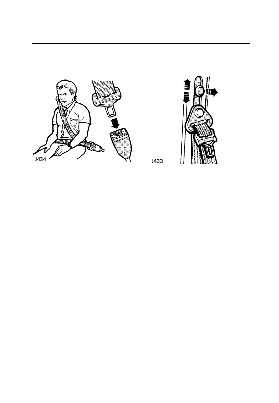
Fastening the inertia reel belts
Draw the belt over theshoulder andacross
the chest, and then insertthe metaltongue
plate into the lock nearestthe wearer- a
’CLICK’ indicates thatthe beltis securely
locked.
In somecircumstances, perhapsdue tothe
vehicle being parkedon aslope, theinertia
mechanism may engage,preventing theinitial
extension of a belt. Thisis nota fault- ease
the belt free and useit.
Adjust the seat belt to eliminate anyslack in
the webbing. DO NOT slackenthe webbingby
holding the belt away fromthe body- tobe
fully effective, theseat beltmust remain in full
contact with the body at all times.Also,
ensure that the lap beltfits aslow onthe hips
as possible and that theshoulder beltpasses
across the shoulderwithout slippingoff or
pressing on the neck.
Upper anchorage adjustment
(front seats only)
The height of the seat belt upperanchorage
can be adjusted for comfortAND safety.Pull
the button out to raise or lower.For safety,the
seat belt should always beworn withthe
webbing crossing the shoulder midway
between the neck and the edge ofthe
shoulder.
Ensure that the anchorage iscorrectly located
in one of the height positions beforedriving.
25
Seat belts
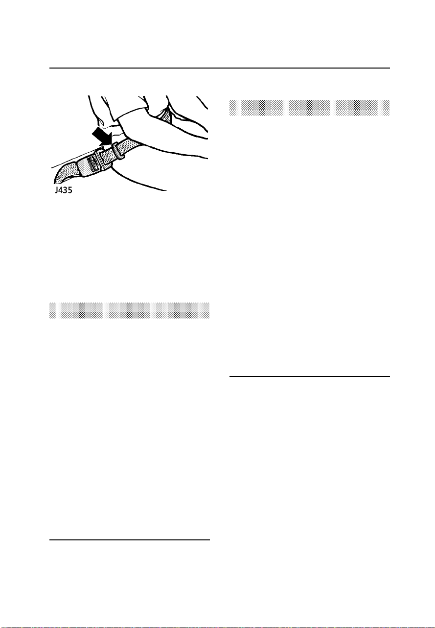
Lap belts
The rear centraland inwardfacing seating
positions are fittedwith lapbelts only.To
adjust, pull the slider alongthe beltand feed
the webbing through the buckleuntil thebelt
is comfortably tight.Fit thebelt aslow as
possible on the hips (neveron theabdomen).
WARNING
Seat belts are designed to bear upon the
bony structure of the body (pelvis, chest and
shoulders), and can only be worn safely with
the seatsin a normal,upright, position.
• ALWAYS fit the lap strap as low on the
hips as possible (never across the
abdomen) and ensure that the diagonal
belt passesacross the shoulder without
slipping off or pressing on the neck.
• ALWAYS ensure that any adjustable seat
back is never reclined more than 15
degrees from the upright position, when
the vehicleis in motion. Seat belts are
only effective when they are properly
positioned on the body - a reclined seat
could allow a passenger to slip under
either the shoulder or the lap belt.
WARNING
• DO NOT fit more than one person into a
belt; this could result in the occupants
striking each other and causing injury in
the eventof a crash.
• DO NOT use, or attempt to fit, a seat belt
that istwisted or obstructed in any way
that couldimpede its smooth operation.
If abelt istwisted, it must be
straightened before use. Using a twisted
or obstructed seat belt could increase
the riskof injury in a crash.
• ALWAYS use the seat belt lock (buckle)
nearest the wearer. If the belt is locked
in thewrong place, the seat belt will not
fit correctly and may ride up over the
abdomen, causing serious internal injury
in acrash.
• DO NOT wear the shoulder belt under
your arm. In an accident this could
increase your chances of being injured.
Wearing seat belts during
pregnancy
The seat belts have beendesigned forall
adults, including pregnantwomen. Ina crash
situation any occupantis lesslikely to be
injured while correctlyrestrained by a seat
belt. However, pregnantwomen shouldwear
the lap belt as low on the hips aspossible to
avoid pressure onthe abdomen.
Women should consult their doctorto
establish the bestuse ofseat beltsduring
pregnancy.
26

Seat belts
CHILD RESTRAINTS FOR SMALL CHILDRENAND BABIES
Infants and children too smallfor adultseat belts should be restrainedin achild safety seator
restraint system appropriateto their age and/or size, andwhich isapproved for use in your
vehicle. Always ensurethat themanufacturer’sfitting instructionsare followed exactly.
Seat belt locking mechanism
The seat belts fitted tothe twoouter rear
seats, have a special lockingmechanism,
which aids the securing ofchild restraint
systems. The mechanismis usedto securea
child restraint asfollows:
1. Attach the seat belt to the childrestraint in
accordance with themanufacturer’s
instructions.
2. Insert the metal tongue of the seatbelt
into the lock ensuring thatit engageswith
a ’click’.
3. Pull on the shoulder sectionof thebelt
until it is fully extended.
4. Allow the belt to retract.A ’clicking’sound
will confirm that the mechanismhas
engaged.
5. Remove all slackfrom themechanism, by
pulling upwards on the shoulderbelt,
immediately above thechild restraint.
6. Ensure that the child restraintis held
securely in place;if not,unlatch the belt
and repeat steps 1 to 6.
The centre rearseating positionis fitted with a
lap belt which can bemanually tightenedto
secure the infant or childrestraint system.
Older children shoulduse thelap/shoulder
belt fitted to the outer seating positions.
• DO NOT allow a baby or infant to be
carried on the lap. The force of a crash
can increase effective body weight by as
much as 30 times, making it impossible
to holdon tothe child.
• UNDER NO CIRCUMSTANCES SHOULD A
REARWARD FACING CHILD SEAT BE
INSTALLED IN ANY FRONT PASSENGER
SEAT POSITION.
• Young adultsand children typically
require the use of a booster seat
appropriate to their age and size,
thereby enabling the seat belts to be
properly fitted, reducing the risk of injury
in acrash.
• DO NOT use a child seat that hooks over
the seatback. This type of seat cannot
be satisfactorilysecured, and is unlikely
to besafe for your child.
• Never leave a child unattended in your
vehicle.
WARNING
NOTE: Somechild seatmanufacturers recommendthe installationof a top tether strap thatis
mounted to the vehicle body.Some mayalso provide’generic’ hardwareto installthe tether to the
vehicle body. INSTALLATIONOF THISHARDWARE WILL DAMAGE THE HEADLINEROF THE
VEHICLE. Such damage will not be coveredunder warranty.For cost and installationof Land
Rover approved mounts,please contactyour Land Rover Centreor retailer.
27

Seat belts
Care & maintenance of seat belts
WARNING
• DO NOT allow foreign matter
(particularly sugary food and drink
particles) to enter the seat belt locks such substances can render the locks
inoperative.
• Regularly inspect the belt webbing for
signs of fraying, cuts and wear, also
paying particular attention to the
condition of the fixing points and
adjusters.
• DO NOT bleach or dye the webbing.
Clean the webbing usingwarm water
and non-detergentsoap only - allow to
dry naturally and DO NOT retract or use
the beltsuntil they are completely dry.
• Always replace a seat belt that has
withstood the strain of an impact or
shows signs of fraying.
Testing inertia reel belts
From time to time, carryout thefollowing
tests:
1. With the seat belt fastened,give the
webbing near the buckle aquick upward
pull. The buckle must remainsecurely
locked.
2. With the webbing half unreeled,hold the
tongue plate and give ita quickforward
pull. The mechanism must lock
automaticallyand preventany further
unreeling of the belt.
3. With the seat belt unfastened,unreel the
webbing to the limit of its travel.Check
that unreeling is free fromsnatches and
snags.
If aseat belt should fail anyof thesetests,
contact your dealerimmediately.
28

SRS/Airbag
The airbag supplementaryrestraint system (SRS)provides additional
protection for the driver andfront seatpassenger, in the event ofa
collision or severefrontal impact on the vehicle.
Always remember; the SRS/airbags are a supplementary restraint systemproviding
ADDITIONAL protection in certain types of frontal impact collisionsonly -they DO NOT replace
the needto weara seatbelt. For maximum safety protection in all crash situations, seat belts
must be worn!
How the SRS/airbag works
The airbag supplementaryrestraint system
(labelled SRS), includestwin airbag modules
(shown in illustration)for thedriver and the
front seat passenger.
In theevent of a collision involvinga frontal
impact, the airbag diagnostic controlunit,
monitors the speed of decelerationcaused by
the impact, to determine whetherthe
SRS/airbag should be activated.
If thereis sufficientdeceleration, the system
causes both airbagsto inflate.Inflation is
instantaneous and accompaniedby aloud
noise. Also evidentare tracesof smoke and
powder, which do not indicatea malfunction
of theairbag or the presence offire.
After inflation, the airbag willimmediately
deflate thereby ensuringthat visibilityis not
impaired.
NOTE: TheSRS/airbag is not designed to
activate in allfrontal impacts;most minor
frontal impacts, heavybraking anddriving
over pot holes will notresult insufficient
decelerationto causethe airbagsto inflate.
This does not indicate thatthere isa faultwith
the system. However,if, asa resultof an
impact, you believethe airbagsshould have
deployed and they failed todo so,please call
1(800)637-6837 for advice,or toarrange fora
Land Rover representativeto inspectthe
vehicle to determinewhether thesystem
operated correctly.
29

SRS/Airbag
WARNING
Following inflation, some SRS/airbag
components are hot - DO NOT touch until
they have cooled.
Even with SRS/airbag equipment fitted, seat
belts must ALWAYS be worn because:
• An airbagwill only provide additional
protection in certain types of frontal
collisions. NO protection is afforded
against the effects of side or rear
impacts, roll over accidents, or minor
frontal impacts.
• Inflation and deflation takeplace
instantaneously and will not provide
protection against the effects of
secondary impacts that can occur during
multiple vehicle collisions.
CHILD SEATS
WARNING
DO NOT USE A REAR FACING CHILD SEAT IN
ANY FRONT PASSENGER SEAT LOCATION.If
the passengerairbag inflates, a child in a
rear facing child restraint could be seriously
injured.
Children could be endangered in a crash if
their child restraints are not properly
secured in the vehicle. Be sure to install
child restraints according to the
manufacturer’s instructions.
Under no circumstances should a rear facing
child seat be installed facing forward in any
seating position.
WARNING
The airbagmodule inflates with
considerable speed and force. For your
safety:
An inflatingairbag can cause facial
abrasions and other injuries. The injurious
affects of airbag inflation can be minimised,
by ensuring driver and passenger are seated
correctly, with the seat moved back as far as
is practical, and the seat belts worn
correctly.
NEVER attach accessory items to an airbag
module cover,or place items of hand
luggage orany objects on the top of a
module cover;these could interfere with the
inflation of the airbag,or if the airbag
inflates, be propelled inside the vehicle
causing injury to the occupants.
DO NOT allow occupants to obstruct the
operation of the airbag modules by placing
their feet, knees or any part of their person
in contactwith, or close to, an airbag
module whilethe vehicleis moving.
Activation of an airbag creates dust, causing
possible breathing difficulties for asthma
suffers or other people with respiratory
problems. If an airbag is activated, any
occupant who suffers from breathing
difficulties should; either leave the vehicle
as quickly as possible, or obtain fresh air by
fully opening the windows or doors.
Both front seating positions are equipped
with knee bolsters to provide knee
protection in the event of an impact. DO NOT
modify the bolsters, or mount after market
equipment on or behind them.
30

SRS/Airbag
SRS/airbag warning light
Whenever the starterswitch isturned to
position ’II’, the diagnostic controlunit
monitors the readinessof thesystem’s
electricalcircuits. The elements of the system
being monitored include:
• SRS warning light
• Rotary coupler
• Airbag modules
• Airbag diagnostic controlunit
• Airbag wiring harness
A warninglight mounted on the instrument
panel will alertyou toany malfunctionof the
SRS/airbag. The systemshould alwaysbe
checked by a dealer ifany ofthe following
symptoms occur. Theseindicate afault, which
may result in the SRS/airbagnot operatingas
required in the event ofa frontalimpact.
• The warning light fails toilluminate when
the starter switchis turnedto position’II’.
• The warning light fails toextinguish within
approximatelyfive secondsafter the
starter switch isturned toposition ’II’.
• The warning light illuminates whilethe
vehicle is beingdriven.
WARNING
DO NOT attempt to service, repair, replace,
or modify any part of the SRS/airbag;
tampering could cause inadvertent
activation of the system, resulting in
personal injury.
Service information
Certain components of the SRS/airbagmust
be replaced by a LandRover dealerafter 10
years from the date ofmanufacture (shownon
the certification plateon therear face of the
left hand front door).
ALWAYS contact your dealer if:
• an airbag inflates.
• the front of the vehicleis damaged,even if
the airbag has not inflated.
• any part of an SRS/airbagmodule cover
(the steering wheelcentre pador the
passenger side fasciapanel) shows signs
of crackingor damage.
In addition:
If yousell your vehicle,be sureto informthe
new owner that the vehiclehas anSRS/airbag
system, and make the newowner awareof the
airbag module replacementdate shownin the
Passport to Service.
If thevehicle is to be scrapped;uninflated
airbags are potentiallyvery dangerous and
must be safely deployed ina controlled
environment before avehicle isscrapped.
See your Land Rover Dealeror Centrefor
advice on safe deployment ofSRS/airbags.
31

SRS/Airbag
WARNING
The componentsthat make up the
SRS/airbag are sensitive to electrical or
physical interference, either of which could
easily damage the system and cause
inadvertent operation or a malfunction of the
airbag module. ALWAYS seek the
assistance of a Land Rover dealer to carry
out anyof the following:
• Removal or repair of any wiring or
component in the vicinity of any of the
SRS/airbag components (yellow wiring
harness), including; the steering wheel,
steering column, instrument and fascia
panels.
• Installation of electronic equipment such
as a mobile telephone, two-way radio or
audio system.
• Modification to the front of the vehicle,
including the bumper and chassis.
• Attachment of accessories to the front of
the vehicle,such as a winch or brush
bar.
32
Steering column
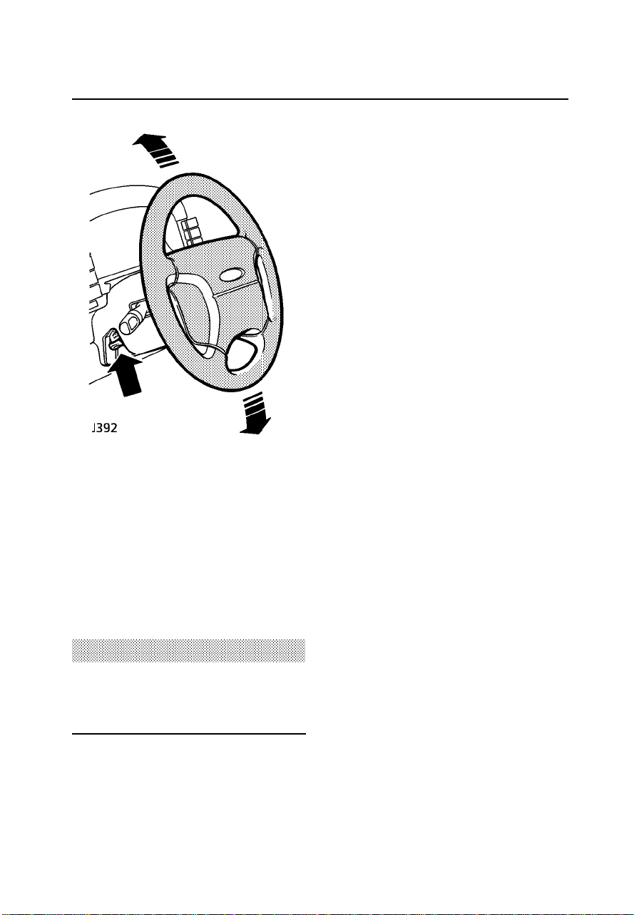
STEERING COLUMN ADJUSTMENT
Adjust the height of the steering columnto
suit your driving position, asfollows:
1. Push the locking lever up(and holdin
position).
2. Move the steering wheel upor downinto
the desired position.
3. Release the lockinglever.
WARNING
DO NOT adjust the height of the steering
wheel while the vehicleis in motion. This is
extremely dangerous.
33

Exterior mirrors
1. Turn the control fully to ’L’ or ’R’ to select
either the left or righthand mirror.
2. With the starter switch turnedto position
’II’, press the top/bottom/left orright of
the control to move the mirror glassto the
required position.
3. When adjustment is complete, returnthe
control to the position midwaybetween ’L’
or ’R’.
The mirror body is designedto foldrearwards
or forwards on impact, andcan bereturned
manually to its normal position.
NOTE: Heatingelements inside eachmirror
operate in conjunctionwith theheated rear
window to disperse ice, mist,or raindrops
from the glass. The right-handexterior driving
mirror is convexand objectsin thismirror are
closer than they appear.
ELECTRIC MIRRORS
34

Instruments
1. Tachometer
Indicates engine speedin revolutionsper
minute. In normal driving conditionsthe
engine is most fuel efficientbetween 2000 and
3000 rev/min.
The vehicle isfitted witha systemwhich
automaticallyrestricts the number of engine
revolutions per minuteonce theengine’s
maximum ’governed’ speedhas beenreached.
2. Speedometer
Indicates road speedin milesand kilometres
per hour.
3. Total distance recorder
Indicates total distancetravelled by the
vehicle.
4. Trip recorder
Records individual journeydistances.
5. Trip recorder reset button
Press to return trip recorderto zero.
Instrument illumination
Rotate the control to increaseor reducethe
intensity of instrumentpanel illumination.
35

Instruments
6. Temperature gauge
Once the engine coolant hasreached its
normal operating temperature,the pointer
should remain betweenthe ’C’ (cold) and
’H’ (hot) segments. If the pointer entersthe
HOT segment, stop the vehicleas soonas
safety permits andseek qualifiedassistance
before continuing.
7. Fuel gauge
The pointer indicatesthe fuellevel even when
the starter switchis turnedoff. After
refuelling, the gaugeslowly changesto the
new level when the starterswitch isturned to
position ’II’.
The AMBER low fuel warning light willindicate
when the remaining fuel isapproximately 2.4
US gallons (9 litres). Ifthe lightilluminates,
refuel at the first opportunity.
WARNING
NEVER allow the vehicle to run out of fuel
(the resultant misfire may destroy the
catalytic converter).
36

Warning lights
The warning lights are colourcoded as
follows:
WARNING
DO NOT drive if a RED warning light remains
on orilluminates whilst the engine is
running.
RED lights are warnings.
AMBER lights are cautions.
GREEN & BLUE lights indicatethat aunit is
operating.
Seat belt - RED
If thedriver’s seat isoccupied the
light illuminates whenthe starter
switch is turned to position’II’. Thelight
extinguishes after approximately5 seconds,
or as soon as the driver’s seatbelt is fastened.
ALWAYS fasten your seat beltBEFORE
driving!
Parking brake & brake fluid -
RED
The light illuminatesas abulb
check when the starter switchis turnedto
position ’II’. It will alsoilluminate when the
parking brake isapplied andthe starterswitch
is in position ’II’.
The light should extinguish whenthe parking
brake is fullyreleased or shortly after the
electricalcircuits are switched on. If the light
illuminates whilst driving,a faultwith the
braking system isindicated. Stopthe vehicle
as soon as safety permitsand seekqualified
assistancebefore continuing.
WARNING
Do not drive the vehicle while the brake
warning light is illuminated.
Transmission oil temperature
- RED
Illumination indicates that
gearbox oil temperatureis high(most likely to
occur in very hot weatherduring continuous
high speed driving, or whilsttowing heavy
loads on steep inclines, orif theparking brake
been accidentally appliedwhile driving).
If thelight illuminates, reducespeed. If the
light remains on, stop thevehicle anddo not
drive until it has extinguished.
37
Warning lights
Hazard warning lights - RED
Illuminates when the hazard
warning lights areflashing.
Low oilpressure - RED
The light should extinguish when
the engine is started. Ifthe light
remains on or illuminates whilstdriving, STOP
THE VEHICLE IMMEDIATELY and seek
qualified assistance. Alwayscheck oil levels
when this light illuminates.
WARNING
Do not drive the vehicle while the low oil
pressure warning light is illuminated.
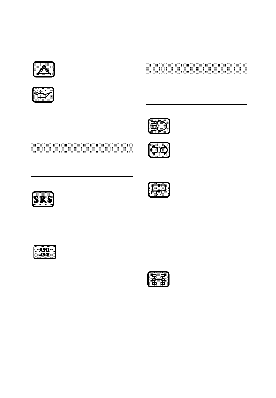
SRS/airbag - RED
The light illuminateswhen the
starter switch isturned to
position ’II’ and extinguishes afterabout 8
seconds. If the light illuminatesat anyother
time, the system is faulty- seekqualified
assistanceurgently.
Anti-lock braking system -
AMBER
The light illuminateswhen the
starter switch isturned toposition ’II’
indicating that the ABS systemis performinga
self check. If no faultsare found,the light
extinguishes briefly, beforeilluminating again
and remaining on until thevehicle exceeds7
km/h (5 mph). If the light remainson or
illuminates whilst driving,there is a fault with
the system: this means thatone ormore
wheels are not under ABScontrol andmay
lock under heavybraking orin slippery
conditions. On completionof yourjourney,
seek assistance fromyour dealerbefore
further vehicle use.
WARNING
Extreme caution should be exercised when
driving with the warning light illuminated,
ABS may not be working!
Headlight high beam - BLUE
Illuminates when the headlights
are on high beam.
Direction indicators - GREEN
Illuminates when the direction
indicators are flashing.If thelight
does not illuminate, this mayindicate a bulb
failure in one of the direction indicatorlights.
Trailer direction indicators -
GREEN
Illuminates in conjunctionwith
the vehicle directionindicator lights to show
that all trailerindicator lights are functioning
correctly. In the event ofa bulbfailure, the
warning light flashesonce andthen remains
off.
NOTE: Whena traileris not fitted, the
warning light willflash onceeach time the
direction indicator switchis operated.
Differential lock - AMBER
Illuminates whenever the
differential lock isengaged.
If thelight remains on after thedifferential
lock lever ismoved tothe disengaged
position, transmission ’windup’ maybe
present. Reversing fora shortdistance and
then going forward will usually’unwind’ the
transmission. If the light remainson, contact
your dealer assoon aspossible.
38

Warning lights
Battery charging - RED
The light illuminatesas abulb
check when the starter switchis
turned to position ’II’ and extinguishes when
the engine is running. If it remainson, or
illuminates whilst driving,a faultis indicated.
Seek qualified assistanceurgently.
Check engine - AMBER
The engine management system
on yourLand Rover is controlled
by a sophisticatedengine controlmodule
which maintains optimumcontrol ofengine
running and emission levels andmonitors the
operation of the sub systemsand
components.
The ’Check engine’indicator illuminatesas a
system check whenthe starterswitch is
turned to position II and should extinguish
when the engine is started.
If anengine operation oremissions problem
is registered bythe enginecontrol module
while the vehicleis beingoperated, the ’Check
engine’ indicator willilluminate.
NOTE: Anincorrectly fitted fuel filler capmay
cause the Check Engine lightto illuminate.
The ’Checkengine’ indicator is illuminated,
and thevehicle drives normally:
Contact your Land Rover dealerto schedulea
service appointment atyour earliest
convenience - YOUMAY STILLDRIVE THE
VEHICLE.
The ’Checkengine’ indicator is flashing
and/or the vehicle does not drive normally:
Avoid high speeds and seekimmediate
assistancefrom yourLand Roverdealer.
Emission maintenance
reminder- AMBER
Illuminates when the vehicle
reaches approximately 50,000miles (80,000
kilometres).When thisoccurs take the vehicle
to yourLand Rover dealer fora special
emission related serviceto be carried out.
Brief illumination (3seconds) willalso occur
as a bulb check when the starterswitch is
turned to position ’II’.
IMPORTANT INFORMATION
AUDIBLE WARNINGS
Driver’s seat belt reminder
A chimewill sound for up to 6 seconds if
the starter switchis turnedto position’II’
when the driver’sseat beltis unfastened.
Starter key warning
A chimewill sound if the key isleft inthe
starter switch whenthe driver’sdoor is
opened.
Lights on warning
A chimewill sound if the lights areleft on
after the starterswitch isturned off.
Transfer box warning
(automatics only)
A warningchime willsound wheneverthe
transfer box gearlever isin the neutral
position.
39

Lights & indicators
Direction indicators
Move the lever down to indicate aLEFT turn,
and up to indicate a RIGHT turn(the GREEN
warning light on the instrumentpanel will
flash in time with the direction indicators).
Hold the lever part-way upor downagainst
spring pressure toindicate alane change.
Side, tail and instrument panel lights
Turn lighting switch to position1.
Turn lighting switch to position2.
Daylight running lights
With the lighting switch off,the daylight
running light systemilluminates the headlight
low beams as soon asthe starterswitch is
turned to position ’II’. The instrument panel
illumination remains off.
Headlights
(Canada only)
Headlight high and low beams
Pull the lever fully towardsthe steeringwheel
to changeheadlight beams(BLUE warning
light glows when the headlightsare onhigh
beam).
To flashthe headlights, pull thelever part way
towards the steeringwheel andrelease.
’Lights on’ warning chime
If thelights are lefton afterthe starterswitch
is turned off, a warning chime willsound
when the driver’sdoor isopened. Thechime
will cease assoon asthe lightsare switched
off orwhen the driver’sdoor isclosed.
40

Wipers & washers
WINDSCREEN WIPERS
The wipers and washers willonly operate
when the starter switch isturned toposition
’II’.
• Single wipe
Pull the lever down andrelease
immediately.
NOTE: Withthe leverheld down, the wipers
will continue operatingat highspeed untilit is
released.
• Intermittent wipe
Turn switch to first position.
• Normal speed wipe
Turn switch to second position.
• Fast speed wipe
Turn switch to third position.
• Variable delay (intermittentwipe)
Rotate the switch to varythe delay
between wipes.
41
Wipers & washers
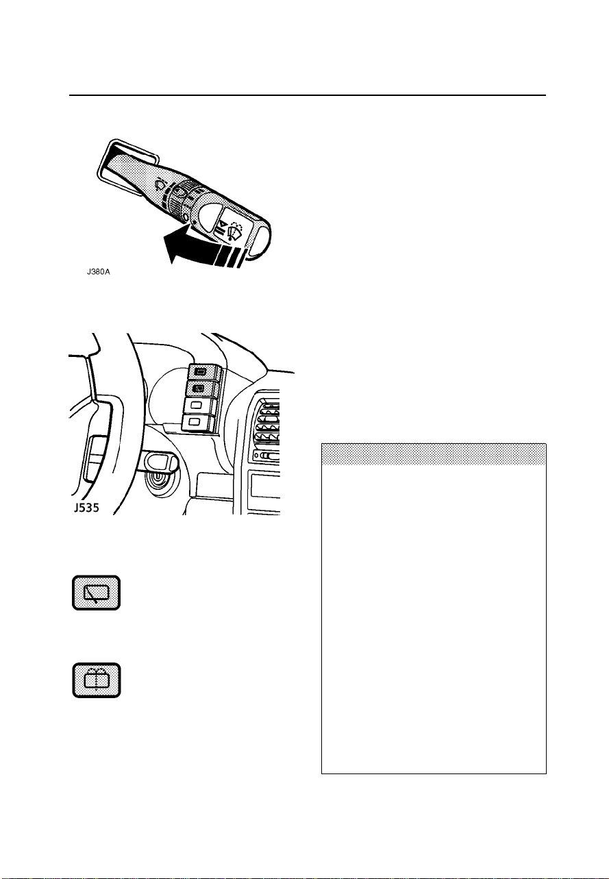
Rear window wiper
Press to operate: after
continuously wiping 3 or 4 times,
the wiper operatesintermittently (approx once
every 6 seconds)until switchedoff.
Rear window wash/wipe
Press and hold switch forthe
required duration of window
washing. The wiper operates automatically
during washing and continues fora further3
wipes after the switch isreleased.
WINDSCREEN WASHER
Pull the lever towards thesteering wheel. The
windscreen wipers willoperate half a second
after the washers,and thenfor aslong asthe
lever is heldin thisposition; thewipers
continuing for a further 4 seconds afterthe
lever is released.
HEADLIGHT WASHERS
The headlight washersoperate automatically
whenever the windscreenwashers are
operated, provided theheadlights are
illuminated on low beam.
NOTE: Ensurean approvedscreen washer
solvent is used in thewindscreen washer
reservoirto preventfreezing.
IMPORTANT INFORMATION
• DO NOT operatethe wiperson adry
screen.
• In freezingor very hot conditions,
ensure that the blades arenot frozen
or stuck to the glass.
• In winter,remove any snow orice
from around the arms and blades,
including the wiped area ofthe
windscreen and the heater air
intakes.
NOTE: Ifthe rearwiper blade sticksto
the glass, a thermal cut-outmay
temporarily prevent thewiper motorfrom
operating. If this is thecase, switchthe
wiper off, free it from the obstructionand
wait for a few secondsbefore switching
on again.
42
Switches
Heated rear window
Press to operate; press asecond
time to switch off. The indicator
light in the switch illuminateswhile the
heating elements areswitched onand
extinguishes when theyare turnedoff. Note
that the heated rear windowoperates only
with the engine running.
After 15 minutes continuous operation,the
heater switches offautomatically.
WARNING
DO NOT stick labels over the heating
elements, and DO NOT scrape or use
abrasive materials to clean the inside of the
rear window.
NOTE: Thefunctions ofthe rearwindow
wiper and rear window wash/wipeswitches
are described under’Wipers & washers’.
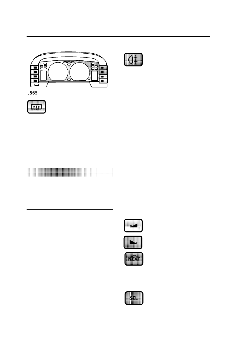
Rear fog lights
Press to operate, press asecond
time to switch off. The rear fog
guard lights will ONLY operatewhen the
headlights (or front fog lights)are switched
on, togetherwith the starter switchturned to
position ’II’ and extinguish whenthe
headlights are switchedoff. Switchingoff the
headlights (or front fog lights)or turningthe
starter switch to position ’0’,will automatically
extinguish the rearfog guardlights. ALWAYS
remember to switch the rearfog lightsoff as
soon as visibilityis clear.
REMEMBER; use only when visibilityis
severelyrestricted - in clear conditions,fog
lights can dazzle other roadusers.
RADIO REMOTE CONTROLS
These switches areof thepressure type; push
in to operate, and releaseto stop.
Depending upon the radio/cassette player
fitted to your vehicle, theswitches described
below MAY have additional functionswhen
used in conjunction with theradio controls.
For additional information,see theRadio
Operations section of this handbook.
Radio - volume up
Press to increasethe volume.
Radio - volume down
Press to reduce the volume.
Seek
Press to seek for theNEXT radio
station on the selected
waveband. If the vehicle isequipped witha CD
autochanger, this controlcan alsobe used to
select the NEXT track ona compactdisc.
Waveband
Press to change waveband.
43

Switches
Hazard warning lights
Press to operate; all thedirection
indicator lights (includingthose
fitted to a trailer) willflash in conjunction with
each other. Use ONLY inan emergencyto
warn other road users whenyour stationary
vehicle is causingan obstruction,or is in a
hazardous situation. Rememberto switchoff
before moving away.
Horn
To operate,press the the hornsymbol edges
of thesteering wheel pad.
Cruise control master switch
The function of the cruisecontrol master
switch is describedunder ’Cruisecontrol’.
Front fog lights (if fitted)
Press to operate, press asecond
time to switch off (the switch
indicator light illuminateswhen thefog lights
are switched on).
The fog lights can be operated ONLYwhen the
headlights are alsoswitched on(low beam
only). They are extinguished automatically
when the headlights are switchedoff, orare
changed to high beam.
ALWAYS switch the fog lights off when not in
use.
44

Windows
ELECTRIC WINDOWS
The switches on the centreconsole operateas
follows:
1. Right hand front window.
2. Left hand front window.
3. Right hand rear window.
4. Isolation switch for rear doorwindow
switches.
5. Left hand rear window.
NOTE: Rearwindows can also be operatedby
individual window switchesmounted oneach
rear door, providedthe isolationswitch is not
activated.
Operating electric windows
The electric windowscan beoperated when
the starter switchis atposition ’II’and for up
to 45seconds after the starter switchis
turned off (provided a dooris notopened in
the meantime).
Press and HOLD the bottomof aswitch to
lower and the top of a switch to raisea
window. The window will stop moving as
soon as the switch is released.
’One touch’ down
(front windows only)
By firmly pressing(and thenreleasing) the
bottom of a switch, a front window will open
fully at a single touch.Window movementcan
be stopped at any time by BRIEFLYpressing
the top of the switch.
WARNING
Accidental closing of a window on fingers,
hands or any vulnerable part of the body,
can result in serious personal injury.
Always observe the following precautions:
• ISOLATE the rear window switches when
carrying children.
• ENSURE children are kept clear whilst
raising or lowering windows.
• NEVER leave children alone in the
vehicle.
• ENSURE that all adult passengers are
familiar with the controls and the
potential dangers of electrically
operated windows.
Isolation switch
Press once to isolate therear window
controls; press again(switch staysin) to
restore independent control.
Always isolate therear windowswitches when
carrying children.
45

Sunroof
ELECTRIC SUNROOFS (iffitted)
An electricsunroof canbe operatedwhen the
starter switch isat position’II’, and for up to
45 secondsafter the starter switchis turned
off (providedno door is opened in the
meantime).
The roofs open and closein twoseparate
phases as follows:
To TILTthe roof:BRIEFLY press the upper
portion of the switch once - theroof will
automaticallymove tothe tiltedposition.
To OPENthe roof: press the upper portionof
the switch BRIEFLY a secondtime -the roof
will continue slidinguntil itis fullyopen.
To CLOSEthe roof: press and hold the lower
portion of the switch until the roofhas moved
to therequired position.
NOTE: Ifthe roofis obstructedfor more than
7 secondswhilst opening or closing,an
automatic cut-out willtemporarily prevent the
sunroof motor from operating.
The rear sunroof can alsobe operatedfrom a
separate switch mountedin therear roof
lining, provided the isolation switchis not
activated.
1. Front sunroof operatingswitch
2. Rear sunroof isolationswitch.
Always isolate therear sunroofwhen
driving with childrenin therear of the
vehicle.
3. Rear sunroof operatingswitch.
WARNING
Accidental closure of the electrically
operated sunroof on fingers, hands or on
any other vulnerable part of the body can
result in very serious injury.
Always observe the following precautions:
• ENSURE passengers are kept clear while
closing the roof, particularly when
closing the rear sunroof using the front
switch.
• NEVER leave children alone in the
vehicle.
• ENSURE that all adult passengers are
familiar with the controls and the
potential dangers of operating the
electric sunroof.
• DO NOT allow passengers to extend any
part of their bodies through the sunroof
while the vehicle is moving.
• DO NOT operate the sunroof in freezing
conditions or when the roof panel is
covered with ice or snow.
46
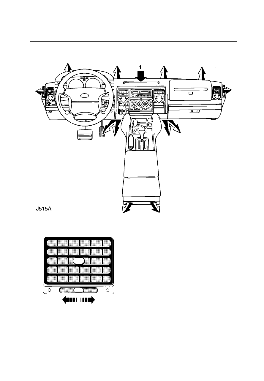
Heating & ventilation
The location of air ventsis shown
by the air-flow arrows inthe
picture. The temperatureof air
supplied to each vent iscontrolled
by the heater.
NOTE: Vent (1) is designedto keep
the audio unit cool. There is noair
flow from this vent.
Face level vents
Each vent can be opened or closedby rotating
the thumbwheel: left to open, right to close.
Direct the flow of airby movingthe controlin
the centre of the louvres.
To ensurebest ventilationand minimum
noise, the vents should befully open
whenever the airdistribution controlis set to
face level.
47

Heating & ventilation
2. Air distribution control
Rotate to select the requireddistribution
of air:
Air to face vents
(to ensure best performance, the
face level ventsmust beopen).
HEATER CONTROLS
1. Temperature controls
The left hand control variesair
temperature from thevents onthe leftside
of thevehicle. The righthand control
adjusts air temperaturefrom thevents on
the right side.
Rotate each controlclockwise (towards
the RED segment) to increasethe air
temperature, or counter-clockwiseto
reduce the temperature.
Air to face vents andfoot outlets
(to ensure best performance, the
face level ventsmust beopen).
Air to foot outlets
Air to foot outlets and windscreen
(recommended for clearingmild
windscreen misting)
All air to windscreen
(recommended for clearingheavy
windscreen misting)
3. Air blower switch
Move the control to the right to
progressivelyincrease the fan speed. With
the control at ’0’ the fan is stationary and
the volume of air enteringthe passenger
compartment is solelydependent uponthe
ram effect of the vehiclemoving through
the air.
NOTE: Toprevent theingress of air from
outside the vehicle,press theair recirculation
control (described onthe followingpage).
48

Heating & ventilation
4. Air recirculation control
Press to recirculateair inside the vehicle
(indicator light illuminates).
The air recirculationmode preventsthe
heating system fromtaking infresh air
from outside the vehicle. Instead,the air
already inside thevehicle is recirculated,
thus preventing the entry oftraffic fumes.
In coldweather air recirculation also
enables warmer airto beused todefrost
the windscreen when the engineis still
cold.
WARNING
The airrecirculation mode can cause the
windscreen to mist. If this happens, switch
off airrecirculation immediately.
NOTE: Theair blowerswitch and air
recirculationcontrol willonly operate with the
starter switch atposition ’II’.
5. Air conditioning switch
The air conditioning system supplies
cooled, dried, airthrough theselected
vents when the air bloweris operating.
With the engine running, pressthe switch
to operate(the indicatorlight inthe switch
illuminates when theair conditioningis
switched on).
6. Rear air conditioning switch (if fitted)
The rear air conditioning systemis
controlled by two-wayswitches situatedin
the front control panel (6)and inthe rear
roof lining illustratedabove. Eitherswitch
will operate the system providedthe front
air conditioning systemis alreadyin
operation.
The system suppliescooled, driedair to
the rear passengercompartment through
air vents alsoset intothe rearroof lining.
In addition,the fan speed can also be
adjusted independently byrear seat
passengers; a slidercontrol mounted
below the rear air conditioningswitch in
the rear roof lining, controlsthe flowof air
from the rear vents.
During cold weatherwhen theair
conditioning system isnot inuse, therear
blower and air vents canbe usedas a
ventilation system tosupply recirculated
air to the rear passengercompartment.
49
Heating & ventilation
USING YOUR HEATER
Fresh air entersthe heaterunit through the
grille in front of the windscreen andstale air is
drawn out through vents in the rearof the
vehicle. Ensure thegrille iskept clear of
obstructions (especially snow and ice). Ducts
along the transmissiontunnel provideheating
for rear seat passengers -these must not be
obstructed.
WARNING
To reducethe risk of accidents caused by
poor visibility always scrape frost and snow
from all exterior glass surfaces and clean
snow from hood and roof panel before
moving (see ’Cleaning & vehicle care’).
The following examplesof basicheater
settings are intendedas ageneral guide; the
air distribution, temperatureand blower
controls can then be furtheradjusted tosuit
your comfort requirements.
Always remember thatfull heatingis not
availableuntil theengine hasreached its
normal operating temperature.
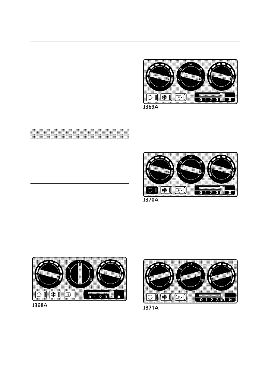
Demisting
Set the controls as shownto obtainthe
maximum flow of heated airfrom the
windscreen and sidewindow vents.
Opening a window may improveventilation.
Defrosting
Set the controls as shownand switchon air
recirculationto preventcold airfrom being
drawn into the vehicle. Turnair recirculation
off assoon as the windscreenis clearto
prevent any possibilityof thewindscreen
misting.
Maximum heating
Set the controls as shown,with theblower at
the slowest speed (position 1)until the
temperature gauge indicatesthat theengine is
warming up - the blower speed canthen be
increased.
Maximum ventilation
Set the controls as shownwith theface level
vents open. Adjust the blowerspeed as
required.
50

Air conditioning
AIR CONDITIONING
The air conditioning system provides
additional cooling to the vehicleinterior, and
also reduces themoisture contentof theair.
Using the air conditioning
The air conditioning system willonly operate
when the air blower isswitched on,and
should only be used when the engineis
running. It is also importantto keepthe
windows (and sunroof) closed during
operation.
Operation of the air conditioningsystem
places an additionalload onthe enginewhich,
in very hot conditions andif theengine is
required to work unusually hard,could result
in high engine temperatures. Ifthe
temperature gauge pointerreaches the RED
zone, the air conditioning isdesigned tocut
out andresume operation whenengine
temperature returns tonormal.
NOTE: Theair-conditioning system usesan
ozone-friendly refrigerant, R134a.
DO NOT use R12 in this system.
It isrecommended that the R134ais recycled
when your air-conditioneris serviced.
Points to remember:
• If thetemperature inside thevehicle is
higher than that outside whenyou start
the engine, it will taketime forthe air
conditioning to become fully effective.It is
best to ventilate the vehicleby openingthe
windows and operating the airblower fora
brief period beforeswitching onthe air
conditioning. Remember toclose the
windows and sunroof whenever theair
conditioning is operating.
• Operating the airconditioning takespower
from the engine and consequently
increasesfuel consumption.
• All air conditioningsystems needto be
operated for a short whileevery week
(even in winter)to maintainthem inpeak
condition.
• The purpose of an air conditioning system
is to dehumidify air. Thesurplus water
produced by this process isexpelled from
the system via drain tubesbeneath the
vehicle. This mayresult ina smallpool of
water forming on the road when the
vehicle is stationaryand isnot a cause for
concern.
• Do not obstruct the air intake forthe rear
air conditioning system.This ispositioned
to thefront of the left hand side facing
seat.
• In highhumidity conditions, slightscreen
misting may be experienced whenthe air
conditioning is turned on. Thisis anatural
occurrance for mostautomotive air
conditioning systems; itis nota faultwith
the system and will clearafter a few
seconds once the air conditioningis
operating.
51

Air conditioning
The following examplesare includedfor your
guidance:
Normal cooling
After starting the engine, switchon theair
conditioning and set the heatingand
ventilation controls asshown. Theblower
speed can be varied tosuit yourcomfort
requirements.
Reducing humidity
Because air conditioningreduces moisture in
the air it can be used todemist windows
quickly in damp weather. Usedin conjunction
with the heater it alsomakes theinterior of the
vehicle warm anddry.
After switching on the airconditioning,
position the controls as shown;this setting
will prove idealfor mostdriving conditions.
Later, adjust the temperature controland
blower speed as required.
Maximum cooling
Start the engine and switchon theair
conditioning. Set the blower tomaximum
speed and press the airrecirculation control
to preventwarm airfrom beingdrawn intothe
vehicle from outside.
Once the interioris cool,switch offthe air
recirculationcontrol (toallow fresh air to enter
the passenger compartment)and resetthe
blower speed to suit yourrequirements.
52

Interior equipment
FRONT INTERIOR LIGHT
With the switch midway betweenthe ’ON’and
’OFF’ positions, thelight willilluminate
automaticallywhenever adoor isopened.
Automatic operation
The front and rear interiorlights illuminate
automaticallywhenever adoor isopened, and
remain illuminated forapproximately 15
seconds after ALL the doorsare closed,or
until the starter switch isturned on.
After driving, the interior lightswill fade and
then extinguish as soon asthe lastdoor is
closed.
NOTE: Ifa doorremains open for eight
minutes, a ’time-out’function willextinguish
the lights to avoid dischargingthe battery.
LOADSPACE LIGHT
Illuminates automatically wheneverthe rear
door is opened and extinguisheswhen the
door is closed.
GLOVEBOX LIGHT
Illuminates automatically wheneverthe
glovebox is opened, provided thesidelights
are switched on, and extinguisheswhen the
glovebox is closed.
CLOCK
The digital clockdisplay illuminateswhen the
starter switch isturned onand dims
automaticallyfor nighttime viewing,when the
sidelights are illuminated.
To adjustthe time, use a ball-point penor
similar probe to press thehour (left-hand)and
minute (right-hand) timecontrols, untilthe
correct time isdisplayed.
REAR INTERIOR LIGHT
Press switch to manually illuminate(or
extinguish) light.
NOTE: Theclock willneed to be reset if the
battery is disconnected.
53

Interior equipment
FRONT ASHTRAY
Push the front of the ashtray to open. To
remove the interiorcompartment, openthe
ashtray fully andthen pressdown onthe
release plate (arrowedin illustration).
CIGAR LIGHTER
With the starter switch turnedon, pressthe
centre of the lighter into heatup. Whenit has
reached the correcttemperature it will partially
eject and can then be withdrawn foruse.
• ONLY hold the cigar lighterby thehandle.
REAR ASHTRAY
To remove,disengage thelower pivotby
pushing the outer edge of the ashtray
upwards at an angle.
Refit by locating the upperpivot andthen
easing the ashtrayinto aposition wherebythe
lower pivot can also beengaged.
WARNING
DO NOT use the ashtray for disposing of
waste paper or other combustible items.
54
Interior equipment
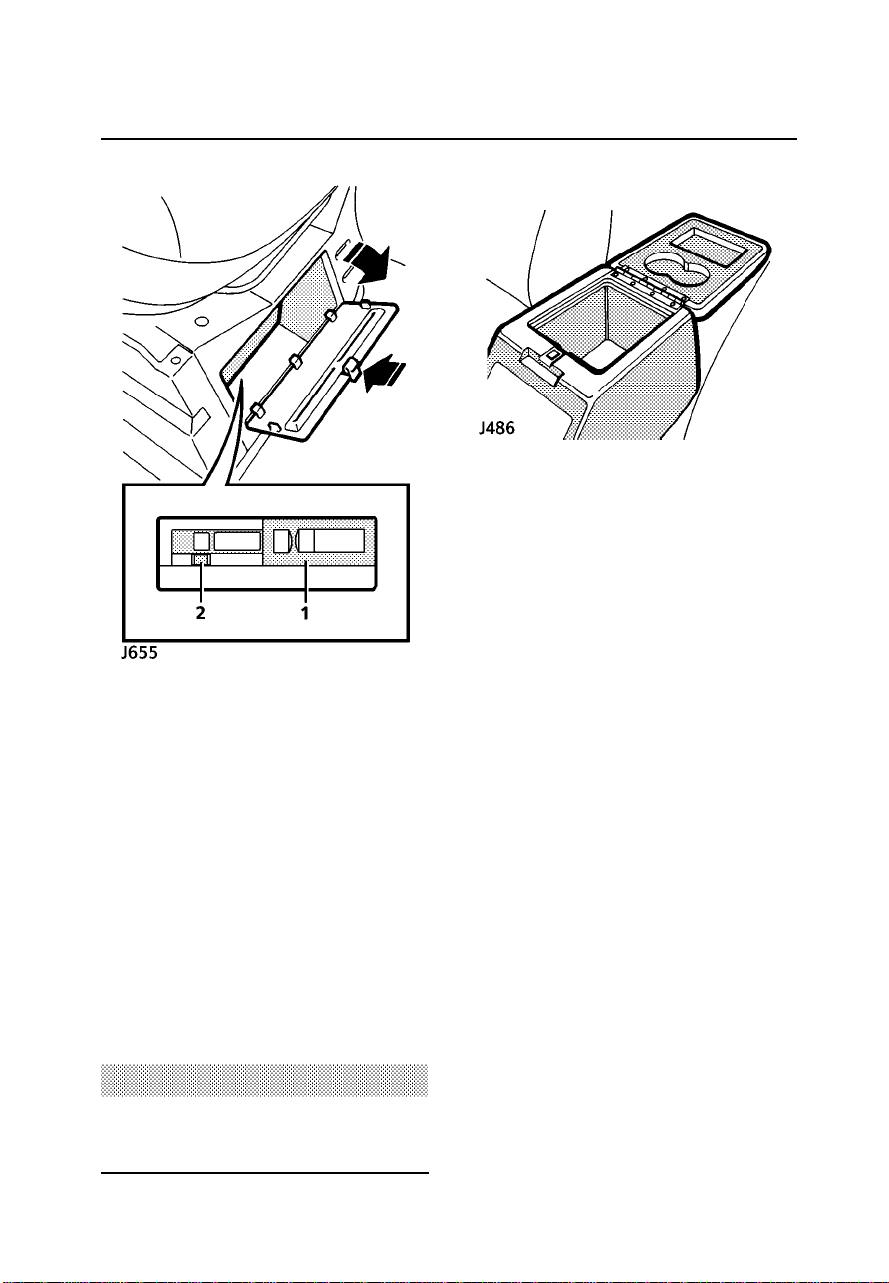
CD AUTOCHANGER (iffitted)
The CD autochanger is locatedunder theleft,
front seat, behind a removablepanel.
To gainaccess to the autochanger,depress
the catch (arrowedin illustration)and remove
the panel.
To removethe magazine
Slide the autochangercover (1)FULLY open
and press button (2) to eject themagazine.
Keep the sliding cover closed,to preventdust
and dirt from entering theautochanger.
Information about loading and unloadingthe
magazine can be found in ’In-car
entertainment’.
CUBBY BOX
NOTE: Therecesses in the underside ofthe
lid are for cups or drink cans.
WARNING
DO NOT insert or eject the magazine while
driving.
55

Interior equipment
CUP HOLDER
Push leading edge of trayto open.
ILLUMINATED VANITY MIRRORS
With the starter switch inposition ’I’or ’II’,
open the mirror cover toilluminate. Close the
cover to extinguishthe lights.
INTERIOR REAR-VIEW MIRROR
The interior mirroris equippedwith an
automatic dimming function,which operates
when the centre button (arrowedin
illustration)on thebase ofthe mirroris
pushed and the starter switchis inposition ’I’
or ’II’. An indicator lightconfirms thatthe
dimming function is operating.
When powered, the mirror willreduce glare
from following vehiclesat night.Pressing the
button asecond time returnsthe mirrorto its
normal reflective state.
Map readinglights
Two mapreading lights aremounted onthe
underside of the mirror. Theseare individually
controlled by the push buttonson eitherside
of theauto-dim mirror switch.
56
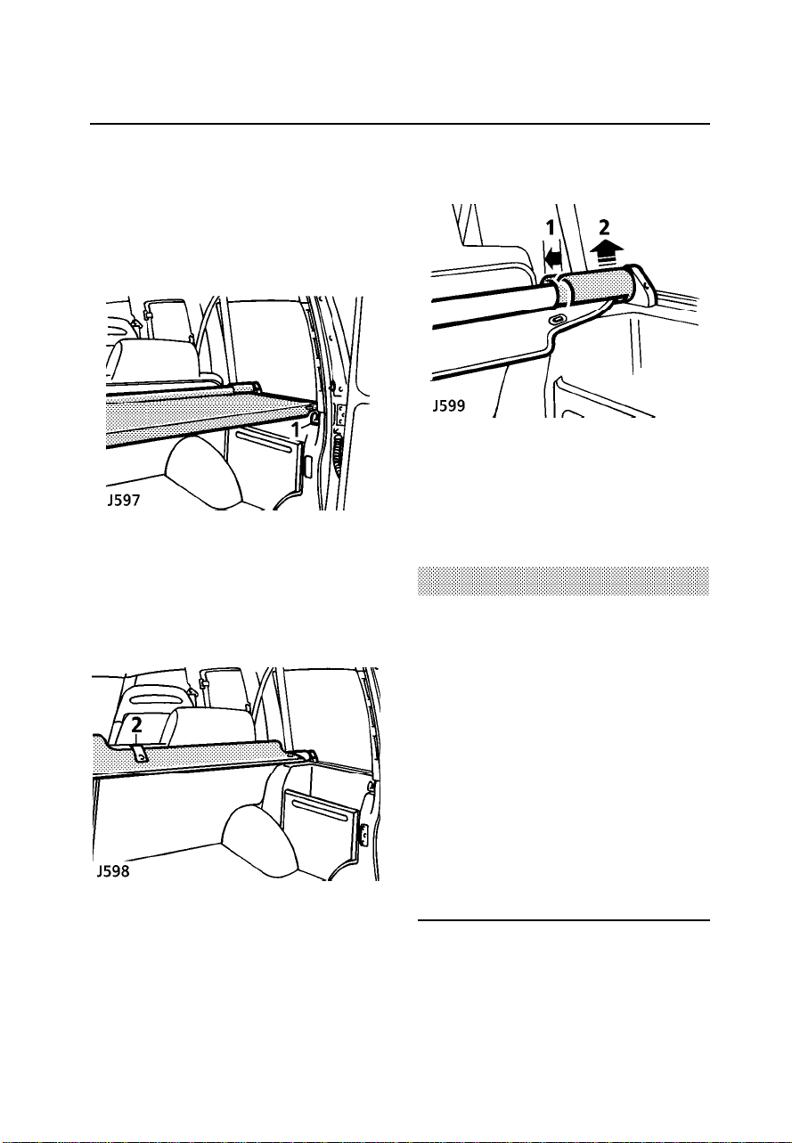
Loadspace cover
LOADSPACE COVER
The rear loadspacecover isa spring loaded
roller blind, whichcan beretracted when not
in use.
Lift the cover over thehooks (1)and allowit
to retract.Secure thecover inits retracted
position with the retaining strap(2), attached
to therear seat back.
To removethe loadspacecover:
1. Slide the plasticsleeve awayfrom the
retaining mount.
2. Lift the cover to disengagethe sidespigot.
WARNING
The loadspacecover is not designed to carry
luggage orloose items - these may obscure
vision and could become dangerous
projectiles in the event of a sudden stop or
collision.
All equipment, luggage or tools carried in
the loadspaceshould be secured to
minimise the risk of injury to the driver and
passengers in the event of an accident or
emergency manoeuvre.
DO NOT store the loadspace cover loose in
the vehicle.
57

Rear step
REAR STEP (if fitted)
Press down to lower the step. Thestep will
automaticallyreturn toits stowedposition
when not in use.
58

SECTION 3
Driving & operating
Section Contents Page
Starter switch & steering lock 61....................
Starting & driving 63......................................
Catalytic converter 66.....................................
Fuel 68............................................................
Manual transmission 72.................................
Automatic transmission 73.............................
Transfer gearbox 76.......................................
Braking systems 81........................................
Cruise control 86............................................
Towing & load carrying 88.............................
Emergency starting 92....................................
Vehicle recovery 94........................................
Long distancetowing 94................................
59

60

Starter switch & steering lock
STEERING LOCK
To unlockthe steering
Insert the key FULLY andturn thestarter
switch to position ’I’ whileturning the
steering wheel slightly.The turningmovement
is necessary todisengage thelock.
To lockthe steering
Turn the key to position ’0’ and withdraw it
from the starter switch. Thenturn thesteering
wheel towards the straight aheadposition
until the lock engages.
WARNING
STARTER SWITCH
The starter switchis locatedto theright of the
steering column, and uses thefollowing
sequence of key positions tooperate the
steering lock, electricalcircuits andstarter
motor:
Position ’0’
• Steering locked (ifkey isremoved).
• Most lighting circuitsare operational,
including: sidelights, headlights,hazard
warning lights and rear foglights.
Position ’I’
• Steering unlocked.
• Clock, radio/cassette/CD playerand cigar
lighter can be operated.
Position ’II’
• All instruments, warninglights and
electricalcircuits are operational.
Position ’III’
• Starter motor operates.
Release the keyimmediately after the
engine starts (thekey willautomatically
return to position ’II’).
NOTE: Onautomatic models,’P’ or ’N’ must
be selected beforethe enginewill start.
NOTE: Onautomatic models,’P’ must be
selected before thestarter keycan be
removed.
Once the steering lock is engaged, it is
impossible to steer the vehicle. DO NOT
remove the key or turn the starter switch to
position ’0’ while the vehicle is in motion.
61

Starter switch & steering lock
WARNING
To preventthe steering column lock
engaging itis most important that before the
vehicle is moved in any way, the key be
inserted in the lock and turned to position
’I’. If, due to an accident or electrical fault,
it isnot considered safe to turn the key,
disconnect the negative lead of the battery
and thenturn the key.
WARNING
Your vehicle has a higher ground clearance
and, hence, a higher centre of gravity than
ordinary passenger cars, to enable the
vehicle to perform in a wide range of
off-road applications. An advantage of the
higher ground clearance is a better view of
the road,allowing you to anticipate
problems. The Discovery is not designed for
cornering at the same speed as
conventional passenger cars, any more than
a lowslung sports car is designed to
perform satisfactorily under off-road
conditions. As with other vehicles of this
type, failure to operate the Discovery
correctly, may result in loss of controlor
vehicle rollover.
62

Starting & driving
STARTING
WARNING
The catalyticconverter is easily damaged by
improper use, particularly if the wrong fuel
is used, or if an engine misfire occurs.
Before starting the engine anddriving,
ENSURE that you are familiarwith the
precautions shown under’Catalytic Converter’
later in this section.
In particular,you shouldbe awarethat ifthe
engine fails to start, continueduse ofthe
starter will resultin unburntfuel damaging the
catalytic converter.
Starter operation
1. Check that the parking brakeis applied
and that the gear leveris inneutral (’P’ or
’N’ for automatic transmission).
2. Switch off all unnecessary electrical
equipment.
3. Turn the starter switch toposition ’II’and
then on to position ’III’ to operatethe
starter motor. DONOT pressthe
acceleratorpedal whilestarting.
RELEASE THE KEY as soon as the engine
is running.
In temperateclimates, DONOT operatethe
starter for longerthan 10seconds. Ifthe
engine fails to start, switchoff andwait 10
seconds before re-usingthe starter.Note that
continued use of the starterwill dischargethe
battery and may also damagethe starter
motor. In temperate climates thebattery
charging and oil pressure warninglights
should extinguish assoon asthe engineis
running.
In verycold climates,if theengine fails to
start after threeattempts, fullydepress the
acceleratorand operatethe startercontinually
for up to 30 seconds, or until the engineruns.
Cold climates
In verycold climates,the batterycharging and
oil pressure warninglights maytake several
seconds to extinguish.Similarly, engine
cranking times willalso increase;at -22° F
(-30° C) the starter motormay needto be
operated continuously foras longas 30
seconds before the engine willstart. For this
reason, ensure thatall non-essentialelectrical
equipment is switchedoff.
Additionally, in verycold temperatures,use of
a 110V AC block heater will improvethe
engine’s starting characteristics.Your Land
Rover dealer canadvise you about the supply
and use of a block heater.
WARNING
Exhaust fumes contain poisonous
substances which can cause
unconsciousness and may even be fatal.
• DO NOT inhale exhaust gases.
• DO NOT start or leave the engine running
in anenclosed unventilated area, or
drive with the rear door open.
• DO NOT modify the exhaust system from
the originaldesign.
• DO repair exhaust system or body leaks
immediately.
• If youthink exhaust fumes are entering
the vehiclehave the cause determined
and correctedimmediately.
63

Starting & driving
Automatic gearbox models
WARNING
When the engine has started, BEFORE
moving the gear selector lever out of ’P’ or
’N’ it is important that the parking brake or
foot brakeis firmly applied and the
accelerator pedal is not depressed otherwise, the vehicle may move
immediately if the gear selector lever is
moved to any of the drive positions (1, 2, 3,
D or R). This is particularly important when
the engineis cold, because the engine will
be idlingat afaster speed than normal. Use
the footbrake to control the vehicle until the
engine iswarm and running at normal
speed.
NOTE: Thefoot brakeMUST be applied
before the selectorcan bemoved from’P’.
IMPORTANT INFORMATION
Before driving:
Learn the layout and functionof allthe
instruments, warning lightsand controls.
Adjust the seat to a comfortable driving
position from which you canensure full
control of the vehicle.
Always start the vehicle andoperate the
controls from the driving position.
Warming-up
DO NOT warm-up the engineby allowingit to
idle at a slow speed.
In theinterests of fueleconomy, itis advisable
to drivethe vehiclestraight away,
remembering that harshacceleration and
labouring the engine before thenormal
operating temperature hasbeen reachedcan
damage the engine.
Power assisted steering
The hydraulic power-assistedsteering is
progressivelygeared; whensteering straight
ahead gearing isrelatively low, but becomes
progressivelyhigher asthe steering wheelis
turned.
NOTE: Powerassistance is dependenton the
engine running. If the engineis notrunning,
greater effort willbe requiredto steer the
vehicle.
WARNING
Under no circumstances must the steering
wheel be held onfull lockfor more than
thirty seconds in any one minute, otherwise
the steeringassembly may be damaged.
Auxiliary equipment
WARNING
Do NOT use auxiliary equipment, such as a
roller generator, which is driven by one
wheel of the vehicle,as this could cause
failure of the gearbox differential. In some
cases the vehicle may attempt to drive itself
forward.
Some local jurisdictions require emission
testing using a two wheel roller
dynamometer. Your vehicle is equipped with
permanent 4-wheel drive and cannot be
safely operated on these machines. For
more information regarding safe emission
testing of your vehicle consult your local
Land Roverdealer or Centre.
64

Starting & driving
VEHICLE HEIGHT
WARNING
The overallheight of your vehicle exceeds
that ofordinary passenger cars (the height
is shown on the underside of the sun visor).
Always be aware of the height of your
vehicle and check the available clearance
before driving through low entrances. This is
particularly important if the vehicle is fitted
with a roof rack or if a sunroof is open.
BREAKING-IN
Proper breaking-in willhave a direct bearing
on thereliabilityand smoothrunning ofyour
vehicle throughout itslife.
In particular,the engine,gearbox, brakesand
tyres need time to ’bed-in’and adjustto the
demands of everydaymotoring andthat is
why, during the first 500 miles (800km), itis
essential to drivewith considerationfor the
breaking-in process andheed thefollowing
advice:
• LIMIT maximum speed to 50 to 60 mph
(80-95 km/h). Initially,drive thevehicle on
a light throttle and onlyincrease engine
speeds gradually oncethe breaking-in
distance has beencompleted.
• DO NOT operateat fullthrottle orallow the
engine to labour in anygear.
• AVOID fast accelerationand heavybraking
except in emergencies.
Initially, the vehicleshould bedriven on a light
throttle. Once the breaking-in distancehas
been completed enginespeeds maybe
gradually increased.
FUEL ECONOMY
Fuel consumption is influenced bytwo major
factors:
• How your vehicleis maintained.
• How you drive your vehicle.
To obtainoptimum fuel economy, it is
essential that yourengine iscorrectly tuned
and that the vehicle ismaintained in
accordance with theservice schedule.
Items such as ignition timing,the conditionof
the air cleanerelement, tyrepressures and
wheel alignment canhave asignificant effect
on fuelconsumption. But above all,the wayin
which you drive is mostimportant. The
following hints may help youto obtaineven
better value fromyour motoring:
• Avoid unnecessary, short,start-stop
journeys.
• Avoid fast startsby acceleratinggently and
smoothly from rest.
• Do not drive in the lower gearslonger than
necessary.
• Decelerategently andavoid sudden and
heavy braking.
• Anticipate obstructions andadjust your
speed accordingly, wellin advance.
DRIVE GENTLY - SAVE FUEL!
65

Catalytic converter
CATALYTIC CONVERTER
The exhaust systemincorporates a catalytic
converter, which reducesemissions from the
engine into environmentallyless harmful
gases.
The catalytic convertercan be easily damaged
through improper use, particularly if the
wrong fuel is used, or if anengine misfire
occurs. For this reason itis VERY
IMPORTANT that you heed the precautions
that follow.
Filling up with fuel
• ONLY use fuel recommended foryour
vehicle.
Starting the engine
• DO NOT continue operating thestarter if
the engine fails to startafter afew
attempts (unburnt fuel may bedrawn into
the exhaust system,thereby damagingthe
catalyst) - seekqualified assistance.
• When starting a COLD engine,DO NOT
drive if a misfire issuspected - seek
qualified assistance.
66

Catalytic converter
Driving
• Provided the engine has reachedits
normal operating temperature,if amisfire
is suspected or the vehiclelacks power
while driving, itmay bedriven SLOWLY
(at risk of damaging thecatalyst) to a
Land Rover dealerfor assistance.
• NEVER allow the vehicle torun outof fuel
(the resultant misfirecould destroythe
catalyst).
• DO NOT induce excessive engine
revolutions or overloadthe engine.
• Engines burning excessiveoil (blue smoke
from the exhaust) will progressively
reduce catalyst efficiency.
• On rough terrain, DO NOTallow the
underside of the vehicle tobe subjectedto
heavy impacts whichcould damagethe
catalytic converter.
WARNING
Exhaust system temperatures can be
extremely high - DO NOT park on ground
where combustible materials such as dry
grass or leaves could come into contact with
the exhaustsystem (in dry weather a fire
could result).
Switching off
• DO NOT switch off the engine whilea
forward or reversedrive gearis selected.
Vehicle maintenance
• Any engine misfirewhich causesthe
Check Engine warning light toflash (see
’Warning lights’), lossof engine
performance or enginerun-on, could
seriously damage thecatalytic converter.
For this reason, it isvital thatunqualified
persons do not tamper with the engine,
and that regular systematic maintenanceis
carried out only by aLand Roverdealer.
• DO NOT run the enginewith aspark plug
lead removed, or use anydevice that
requires an insertinto aspark plug.
67

Fuel
USE ONLY UNLEADED FUEL
Octane requirements
Always use PREMIUMUNLEADED GASOLINE
with a CLC or AKI octane rating of 90 or 92
(95 or 96 RON).
NOTE: Federallaw requiresthat gasoline
octane ratings be posted onthe pumps.The
Cost of Living Council (CLC)octane ratingor
Anti Knock Index (AKI) octanerating shownis
an average of Research OctaneNumber (RON)
and Motor Octane Number (MON).
Using unleaded fuelwith anoctane rating
lower than that recommended, cancause
persistent, heavy ’engineknock’ (a metallic
rapping sound). If severe, thiscan leadto
engine damage.
If heavyengine knockis detectedwhen using
recommended octane ratedfuel, orif steady
engine knocking ispresent whilemaintaining
a steady speed on levelroads, contactyour
dealer for adviceas soonas possible.Failure
to takemeasures to eliminate eithercondition
constitutes misuse ofthe vehicle!
NOTE: Anoccasional, light, engine knock
experiencedONLY forshort periodswhile
acceleratingor climbinghills is acceptable.
WARNING
DO NOT use leaded fuel! Your engine is
designed to use unleaded fuel ONLY.
Unleaded fuel is essential for proper
operation of the emission control system.
Even a very small quantityof leadedfuel will
damage your vehicle’semission control
system and could invalidate theemissions
warranty. In addition, leaded fuelwill damage
the oxygen sensorsin thefuel injection
system and also seriously damagethe catalyst
in the catalyticconverter.
Reformulated gasolines andgasolines that
contain detergents, anti-corrosionand
stability additives arerecommended - they will
help your vehiclemaintain thecorrect level of
emissions and engineperformance.
Fuel system cleaningagents shouldbe
avoided, as many of theseproducts canbe
harmful to gaskets and othermaterials used in
fuel system components.
Driveability
If youencounter driveability, startingand
stalling problems, especiallyin high ambient
temperatures or athigh altitudewhen the
engine is cold, it maybe causedby poor
quality fuel. Try an alternativebrand, and if the
problem persists, seekadvice from your
dealer.
68

Gasoline/oxygenated fuel blends
To avoidinvalidating thevehicle warranty, use
ONLY fuels blendedwithin thefollowing
limits.
1. Up to 15% of Methyl Tertiary ButylEther
(MTBE) and unleaded fuel mix.
2. Up to 15% of Ethyl Tertiary ButylEther
(ETBE) and unleaded fuel mix.
3. Up to 10% of Ethanol (Ethyl or grain
alcohol) and unleadedfuel mix.
Methanol/unleaded fuel blends
In someareas, it is possibleto buyunleaded
fuel that is blended withup to 5% Methanol
(Methyl or wood alcohol) andcosolvents and
corrosion preventatives. Usingthese blends
can cause driveabilityproblems and damage
to thefuel system components.Their usemay
also invalidate thevehicle warranty.
WHEREVER POSSIBLE, AVOID USING FUEL
CONTAINING METHANOL!
Octane enhancers
The use of octane enhancersis not
recommended, and may invalidate thevehicle
warranty.
WARNING
Automotive fuels can cause serious injury,
and evendeath if misused.
Methanol/unleaded fuel blends, even in
small amounts, can cause blindness and
possible death if swallowed. Additionally,
take precautions to prevent methanol from
coming into contact with the skin.
Fuel
Locking and unlocking the fuel filler flap
WARNING
To avoidany sudden discharge of fuel
caused by excessive air pressure,the capis
designed to allow the fuel tankto vent
during the first half turn. DO NOT fully
remove the cap until any pressure has been
released.
Take careful note of warning labels located
around the filler flap.
DO NOT fully fill the tank, if the vehicle is to
be parkedin direct sunlight or high ambient
temperature - expansion of the fuel could
cause spillage.
69

Fuel filling
Filling station pumpsare equippedwith
automatic cut-off sensingto avoidfuel
spillage - onlyfill thetank untilthe filler nozzle
automaticallycuts offthe supply.
DO NOT attempt to fillthe tankbeyond this
point or spillage could resultdue toexpansion
of thefuel.
The reduced diameterfiller neck,accepts
ONLY a narrow filler nozzleof thetype found
on pumpsthat supply UNLEADEDfuel.
Fuel
Empty fuel tank
DO NOT RUN THE FUEL TANK DRY!
Running the fuel tank drycould createan
engine misfire capableof damagingthe
catalytic converter. Itwill also cause the Check
Engine warning light to illuminate.
GAS STATION SAFETY
Petroleum gases arehighly inflammable
and, in confined spaces, arealso
extremely explosive. Alwaystake sensible
precautions when refuelling:
• Switch off the engine.
• DO NOT smoke or usea nakedflame
or light.
• Take care not to spillfuel.
• DO NOT overfillthe tank.
WARNING
Ensure the filler cap is fitted correctly after
refueling, otherwise the Check Engine
warning light may illuminate.
70

Fuel
FUEL CUT-OFF SWITCH
The fuel cut-off switch isa safetydevice
which, in the event of a collisionor sudden
impact, automatically cutsoff thefuel supply
to theengine.
The switch is located inthe engine
compartment on the bulkhead. Afteran
impact, the switch must bereset bypressing
the rubber top (arrowed inillustration) before
the engine can be restarted.
WARNING
ALWAYS check for fuel leaks before
resetting the switch!
71

Manual transmission
MANUAL TRANSMISSION
Manual transmission vehiclesfeature a five
speed main gearboxand atwo speedtransfer
box. In addition, a centredifferential in the
transfer box distributesthe driveto the front
and rear axles,providing permanentfour
wheel drive. Byusing themain gearboxin
conjunction with the transfer gearingten
forward and two reverse speedsare available.
The gear positions for themain gearboxare
shown on the gear leverknob. Notethat when
the main gearbox is inneutral, thegear lever
is spring-loaded toautomatically align
between third and fourth gearpositions.
Clutch
Take care NOTto usethe clutchpedal as a
foot rest.To prevent unnecessary wear,
always keep theleft footaway fromthe clutch
pedal except when changing gear.
Starting and driving
Drivers unfamiliar withthe performance
characteristicsof amanual transmission
gearbox should thoroughlyfamiliarise
themselves with thefollowing instructions
before driving.
• Before starting the engine, ensurethat the
parking brake isapplied andthe main
gearbox lever isin neutral.
• Always start the vehicle fromthe driver’s
position.
• Always depress theclutch whilstchanging
gear, releasing itgently afterwards.
WARNING
DO NOT select reverse gear unless the
vehicle is stationary.
DO NOT attempt to start the engine with the
clutch engaged and the vehicle in gear.
ONLY start the vehicle from the driver’s
position with the transmission in neutral and
the parkingbrake applied.
72
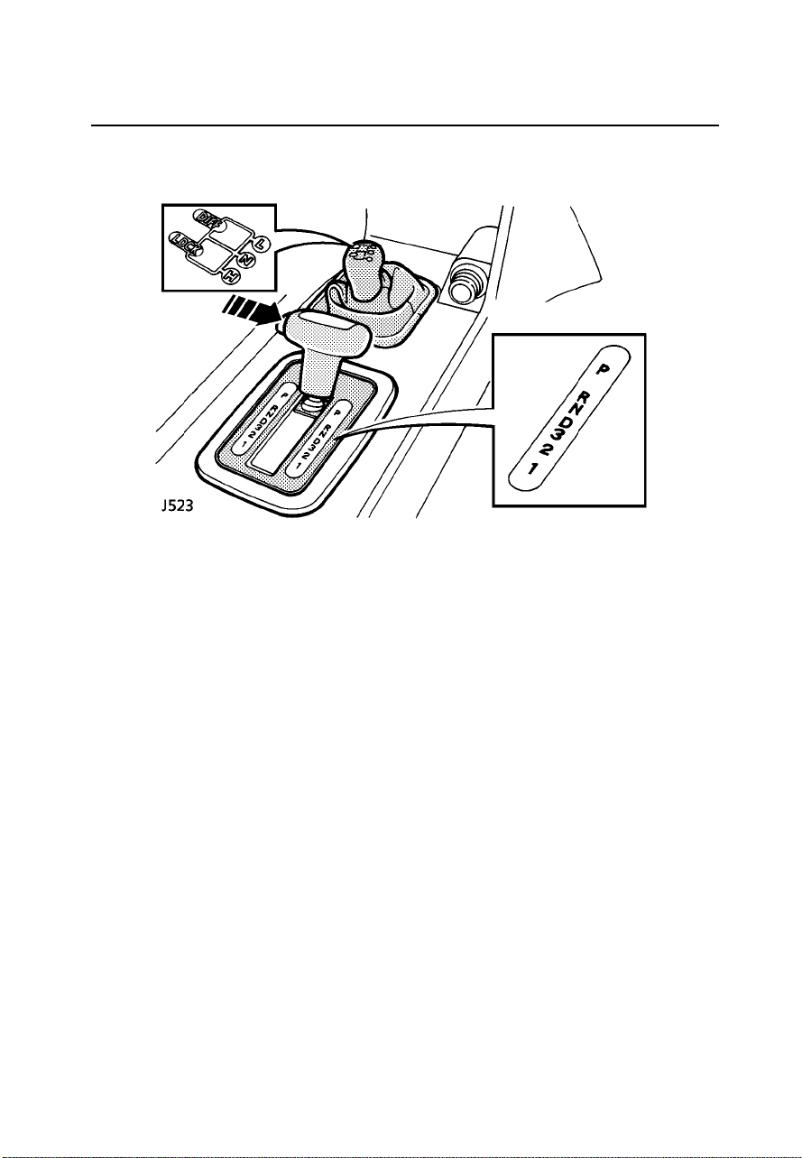
Automatic transmission
AUTOMATIC TRANSMISSION
The automatic transmissionfeatures a four
speed main gearboxwith atorque converter
and a two speed transferbox. Acentre
differential in thetransfer boxdistributes
power to both front and rear axles,providing
permanent four wheel drive. Usingthe main
gearbox in conjunctionwith thetransfer
gearing produces eightforward andtwo
reverse speeds.
Main selectorlever
A springloaded catch,built intothe handleof
the gear selectorlever, restrictsmovement of
the lever, therebypreventing inadvertentgear
selection. Press andhold thebutton (arrowed
in illustration) torelease the catch whilst
moving the lever to therequired position.
NOTE: Gearselection between ’D’and ’3’may
be made without holding in the button.
73

Automatic transmission
Automatic selector lever positions
’P’ (Park)
In thisposition the transmission islocked
to preventthe vehiclefrom rollingaway.
Select ONLY with the vehiclestationary
and the parking brake on.
’R’ (Reverse)
Select ONLY when the vehicleis
stationary.
’N’ (Neutral)
Use this positionwhen thevehicle is
stationary and the engine isto idlefor a
prolonged period (eg. at trafficlights).
’D’ (Drive)
Select ’Drive’ forall normaldriving on
good roadsurfaces; fullyautomatic gear
changing occurs on all forwardgears
according to vehiclespeed andaccelerator
position.
’3’ (1st, 2nd and 3rd gears)
Automatic gear changingis limitedto first,
second and third gears only.Use in
congested traffic conditionsand fortown
driving.
’2’ (1st and 2nd gears)
Automatic gear changingis limitedto first
and second ratios only. Usewhen driving
up steepgradients and for negotiating
very narrow twistingroads. Thisposition
also provides moderateengine brakingfor
descending slopes.
NOTE: Ifeither ’2’or ’1’ is selected from’D’
or ’3’ while the vehicleis travellingat high
speed, third gear will immediatelyengage.
Progressivedeceleration will then cause
downshifts into second then firstgear atthe
appropriate road speeds.
’1’ (1st gear only)
Use on very severe gradients,particularly
when towing, and when maximum engine
braking is required.
WARNING
When parked, always leave the vehicle with
the gearselector in ’P’ (Park) and the
parking brake applied.
NOTE: Thestarter key cannot be removed
unless the gear selector isin ’P’ (Park).
Starting and driving
Drivers unfamiliar withthe performance
characteristicsof automatictransmission
should thoroughly familiarisethemselves with
the following instructionsbefore driving.
• Before starting the engine, ensurethat
both footbrake and parkingbrake are
applied.
• After starting the engine, KEEPBOTH
BRAKES APPLIED before and whilst
moving the selectorlever tothe required
drive position.
• Keep the brakes applied untilyou are
ready to move - remember,once adrive
position is selected,an ’automatic’will
tend to creep forward (orbackward).
• Never ’rev’ theengine whileselecting a
forward or reversedrive gear,or while the
vehicle is stationarywith adrive gear
selected - remember,an ’automatic’will
move immediately whenthe accelerator
pedal is pressed.
74

Automatic transmission
Gear change speeds
With ’D’ selected,the roadspeed at which
gear changes takeplace willvary accordingto
the position of the accelerator:minimum
accelerationwill resultin low road speed gear
changes, while largerthrottle openingswill
cause the main gearbox todelay gearchanges
until faster road speeds havebeen reached
(thereby increasing acceleration).
With practice, gearchanges canbe made to
occur at a wide rangeof differentroad speeds,
depending on acceleratorpedal pressure.
On long inclines, an automaticgearbox will
sometimes change backand forthbetween
gears. This occursbecause thetransmission
does not include a ratiothat isprecisely right
for the particularincline andvehicle loading
circumstances.Excessive gear changingis
wasteful of fuel and resultsin aloss of
momentum. It can be preventedby selecting
the ’3’ or ’2’ positionswhich limitthe gearbox
to lowerratios.
’Kick-down’
To providerapid accelerationfor overtaking,
’kick’ the acceleratorpedal to the full extent of
its travel in a single,quick movement (known
as ’kick-down’). Upto acertain speed, this will
cause an immediatedownshift intothe lowest
appropriate gear, followedby rapid
acceleration.Once thepedal is relaxed,normal
gear change speedswill resume(dependent
upon roadspeed and accelerator pedal
position).
75

Transfer gearbox
TRANSFER GEARBOX
The two speed transfer gearbox,is usedto
select either thehigh orlow rangeof gears
and, in addition, also controlsthe centre
differential (known asthe ’DIFFLOCK’).
A shiftinterlock safetyfeature isfitted which
prevents any transferbox gearselection being
made unless the ignition isswitched onand
the automatic gearboxselector isin the ’N’
(Neutral) position.
High range (’H’)
Use high range for allnormal roaddriving and
also for off-road driving acrossdry, level
terrain.
Low range(’L’)
Use low range gears whenmoving offfrom
rest when towing a heavyload, orin any
situation where lowspeed manoeuvringis
necessary,such asreversing a traileror
negotiating a boulder strewn riverbed; also
use low range for moreextreme off-road
conditions where progressin highrange
cannot be maintained.
Neutral (’N’)
Transfer box in neutral. Inthis position,drive
cannot be transmitted to theroad wheels
regardlessof themain gearselector position.
If, forany reason, the vehicle hasto betowed
on fourwheels, this neutralposition MUSTbe
used (see ’Vehiclerecovery’).
Audible warning
(automatic only)
A constant,high pitched, audible warning
chime will sound whenever thevehicle starter
switch is turned on when the transfergearbox
lever is in the ’neutral’position. The warning
is intended to remind thedriver thatthe
appropriate ’High’ or’Low’ rangegearing
should be engaged.
’Diff-lock’ centre differential
Use the ’unlocked’position, forall normal
driving, and use the ’DIFF-LOCK’position to
improve traction inextreme conditions,where
wheel grip could be lost,such as:wet grass,
mud, sand,ice or snow. Return to the
’unlocked’ position assoon asdry, firm
ground is reached.
DO NOT use the ’diff-lock’unnecessarily!
WARNING
DO NOT attempt to change to LOW range
gears for normal road driving.
76

Transfer gearbox
USING THE TRANSFER GEARBOX
There are two ways ofoperating thetransfer
gearbox lever; the’normal’ methodrecommended for inexperienceddrivers - and
the ’advanced’ methodfor experienced
drivers.
Normal method
Manual models:
With the vehiclestationary andthe engine
running, depress the clutch andthen move
the transfer gearboxlever fullyforward (or
backwards) in TWOdistinct butpositive
moves - ’high to neutral’....’neutral to low’ (or
vice versa).
If thereis resistanceto thegear engaging,do
not forcethe lever. Instead, withthe main
lever in gear,release the clutch momentarily
and then try again.
Automatic models:
With the vehiclestationary andthe engine
running, apply both foot brakeand parking
brake and then move the automatic gearbox
selector to the ’N’ (neutral)position before
moving the transfer lever fullyforward or
backwards to the required position.
If thereis resistanceto thegear engaging,do
not forcethe lever. Instead, withthe engine
running, apply the foot brakeand parking
brake, momentarily engage’D’ on the main
gearbox then return it tothe ’N’position and
then try again.
Advanced method
Manual models:
Changing from high to low onthe move:
With the vehicleslowing toa stopand
travelling NO FASTERTHAN 3mph (5km/h),
depress the clutchand pushthe transferlever
into neutral. Just before theroad wheelsstop
turning (and with the clutchstill depressed)
push the transfer lever fullyforward into ’L’
(low).
NOTE: Usepositive and confident moves, but
do notrush the gear change.
Changing from low to high onthe move:
Changing from ’L’ (low) to ’H’ (high)can be
achieved without stoppingthe vehicle,as
follows:
1. Apply slight backwardpressure to the
transfer gear leverin preparationfor
changing.
2. Then, in three simultaneous moves,
depress the clutch,release the accelerator
and pull the transfer leverinto neutral.
3. Release the clutchpedal forapproximately
3 secondsbefore depressingit againand
moving the transfer lever firmlyinto the
high position. With the new range
selected, push firmlyon thetransfer shift
lever to ensurethe gearis fullyengaged.
4. Finally, select asuitable main gear, release
the clutch and continue drivingin the
normal way.
NOTE: Aftera littlepractice, thisoperation
can be carriedout smoothlyand quicklyby
using firm, positivemoves -but donot rush
the gear change.
77
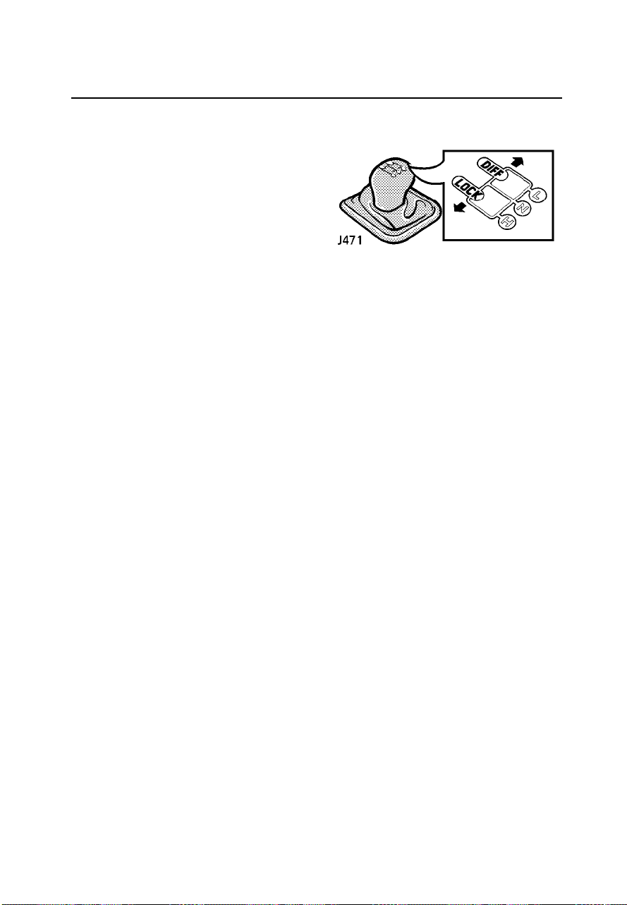
Transfer gearbox
Automatic models:
Changing from ’H’ (high) to’L’ (low)or vice
versa without stoppingthe vehiclecan be
achieved as follows:
Reduce (or increase)the speedof the vehicle
to 5mph (8km/h) and releasethe accelerator.
Select ’N’ withthe maingear selectorand
move the transfer lever quicklyto the required
’H’ or ’L’ position. Finally,reselect ’D’ withthe
main gear selectorand continuedriving as
normal.
NOTE: Thisoperation applies to ’H’ to ’L’ and
’L’ to ’H’ equally.
THE DIFFERENTIAL LOCK
Unlike many four wheel drivevehicles, all
Land Rover vehicleshave permanentfour
wheel drive. Thisis achievedby the inclusion
of alockable differential betweenthe front and
rear drive shafts.With thedifferential locked,
the drive shafts to frontand rearaxles are (in
effect) joined togethercausing bothaxles to
rotate at the same speed.This isa normal
feature with allfour wheeldrive vehicles and
enhances traction ondifficult off-road
surfaces. However, withthe differential
unlocked, the differentrunning requirements
of thetwo axles can be accommodated,
thereby enabling LandRover vehiclesto
operate permanently infour wheeldrive for
both roadAND off-road use.
78

Transfer gearbox
Selecting diff lock
The diff lock can be engaged ordisengaged
either with the vehicle stationary,or when
driving at any road speed,and without
depressing the clutch.However, withthe
vehicle in motion it isESSENTIAL tobe
travelling on firmground, ina straightline,
and without wheel slip.
WARNING
DO NOT engage the diff lock if one or more
wheels are slipping - this could damage the
transmission. If wheels are slipping, ease
off theaccelerator before engaging the diff
lock.
To lockthe differential:
Move the transfer gear leverto theleft - from
either ’H’ (high)or ’L’(low) position (the
warning light on the instrumentpanel will
illuminate).
To unlockthe differential:
Move the transfer gear leverto theright - to
either ’H’ (high)or ’L’(low) position as
required; when the diff lockdisengages the
warning light willextinguish.
When to use the diff lock
As a general rule, thedifferential should only
be locked in order todrive onloose and
slippery surfaces. ALWAYSunlock the
differential for normalroad drivingor as soon
as a hard grippy surfaceis reachedwhether
high or low gears areselected.
NOTE: Avaluable introduction to off-road
driving, which includesmany useful
referencesto thetransfer gearboxand ’diff
lock’, is includedin the’Off-road driving’
section.
WARNING
If thevehicle is driven on normal road
surfaces with the differential locked, the
steering will feel stiff, excessive tyre wear
will occur and the transmission will be
’wound up’. This places excessive strain on
the transmission.
79

Transfer gearbox
Diff lock warning light
The amber warning light onthe instrument
panel illuminates whenthe difflock is actually
engaged - rather than whenit hasbeen
selected. Similarly itwill only extinguishwhen
the diff lock is actuallydisengaged. This
accounts for a slight delaybetween diff lock
deselection and thewarning light
extinguishing, which isquite normal.
IMPORTANT INFORMATION
Transmission ’wind up’
If thewarning light is obviously reluctant
to extinguishafter the diff lockhas been
deselected, some transmission’wind up’
may be present.
Reversing the vehiclefor ashort distance
and then going forward willusually
’unwind’ the transmissionand extinguish
the light and the vehiclecan thenbe
driven as normal.However, ifafter two or
three attempts to ’unwind’ the
transmission the lightremains on,
consult your dealerAS SOONAS
POSSIBLE.
80

Braking systems
FOOT BRAKE
As a safety precaution, thehydraulic braking
system operates throughdual circuits.If one
circuit fails, theother willcontinue to function,
but increasedbrake pedaltravel, greater pedal
effort and longer stopping distanceswill be
experienced.
Power assistance
The braking systemis powerassisted, but
ONLY when the engine isrunning. Without
this assistance greaterbraking effort is
necessaryto safelycontrol the vehicle,
resulting in longerstopping distances.Always
observe the followingprecautions:
• NEVER allow the vehicle tocoast withthe
engine turned off.
• ALWAYS take particularcare when being
towed with the engine turned off.
• If theengine should stop for any reason
while the vehicleis inmotion, bringthe
vehicle to a halt asquickly astraffic
conditions safely allow,and DONOT pump
the brake pedal as thebraking systemmay
lose any remainingassistance available.
Brake pads
Brake pads requirea periodof beddingin. You
should avoid heavybraking, exceptin
emergencies,for atleast thefirst 500 miles
(800 km).
Remember that regularservicing is vitalto
ensure that the brake padsare examinedfor
wear and changed periodically to ensure long
term safety and optimum performance.
WARNING
DO NOT rest your foot on the brake pedal
while travelling as this may overheat the
brakes, reduce their efficiency and cause
excessive wear.
NEVER place additional floor matting or any
other obstruction under the brake pedal.
This restricts pedal travel and braking
efficiency.
NEVER move a vehicle with the starter
switch turned off, because braking
assistance will not be available. The pedal
brakes will still function, but more pressure
will be required.
ALWAYS take particular care when being
towed with the engineturned off.
WARNING
If thebrake warning light comes on when
driving, and the parking brake is fully
released, a fault with the braking system is
indicated. Be prepared for increased brake
pedal traveland then stop the vehicle as
quickly as traffic conditions and safety
permit and seek qualified assistance before
continuing.
DO NOT pump the brake pedal. If the brake
pedal ispumped, the braking system may
lose any remaining assistance available.
81

Braking systems
Wet conditions
WARNING
Driving through water or even very heavy
rain may adversely affect braking efficiency.
Always dry the braking surfaces by
intermittent light application of the brakes,
first ensuring that you are at a safe distance
from other road users.
Parking brake
Unlike most othervehicles, theparking brake
on yourLand Rover operates onthe rear
propeller shaft, andNOT onthe roadwheels.
This may result in slightmovement ofthe
vehicle after theparking brakeis applied.
To engagethe parking brake, depressthe
button andpull the leverup.
To release,pull thelever upslightly, depress
the button and lower the lever.
Always apply the parking brake fully
whenever you park.
When parking on a slope,do notrely onthe
parking brake aloneto holdthe vehicle.On
manual gearbox models,the vehicleshould be
parked in a low forwardgear whenfacing
uphill and in reverse gearwhen facing
downhill. For extrasecurity onsteep slopes,
move the transfer lever intolow rangeand
engage the diff lock.
On automatic gearboxmodels, particularly
when low range is selected,ensure the
parking pawl of the maingearbox hasfully
engaged by carefullyreleasing the foot brake
and allowing the vehicle to’rock’ into ’P’
(park).
WARNING
Always apply the parking brake fully
whenever you park.
DO NOT apply the parking brake while the
vehicle is in motion (except in an
emergency), as this could result in loss of
vehicle control and damage to the
transmission.
DO NOT rely on the parking brake to operate
effectively, if the brake linings have been
subjected to immersion in mud and water
(see ’Off-road driving’ section).
ALWAYS use wheel chocks when jacking the
vehicle. Even with the parking brake
applied, vehicle movement is likely due to
tolerances in the transmission.
82

Braking systems
ANTI-LOCK BRAKES
WARNING
ABS cannot overcome the physical
limitations of stopping in too short a
distance, cornering at high speed, or the
danger of aquaplaning i.e. where a layer of
water prevents adequate contact between
the tyresand road surface.
DO NOT pump the brake pedal at any time;
this will interrupt operation of the system
and mayincrease braking distance.
The factthat a vehicleis fitted with ABS,
must never tempt the driver into taking risks
that couldaffect his/her safety, or that of
other road users. In all cases, it remains the
driver’s responsibility to drive within normal
safety margins, having due consideration for
the prevailingweather and traffic
conditions.
NEVER place additional floor matting, or any
other obstructions, under the brake pedal;
this restricts pedal travel so that braking
efficiency is impaired.
The purpose of anti-lock braking(ABS) is to
allow efficient brakingwithout wheellocking thereby allowing thedriver toretain steering
control of the vehicle.
ABS in action!
Under normal brakingconditions, where
traction is good, the anti-lockbraking system
will not be activated. However,should the
braking force exceedthe availableadhesion
between the tyres and theroad surface,then
the system will automatically come into
operation. This willbe recognisableby a rapid
pulsation felt through the brakepedal.
In normalroad use, in an emergency situation
full braking effortshould alwaysbe applied,
even when the road surfaceis slippery.The
(4-channel) anti-lock brakingsystem
constantly monitors thespeed ofeach wheel
and varies brakingpressure to ensure that
none of the wheels lock.
No matter how hard you brake, youshould be
able to continue steering thevehicle as
NORMAL.
83

Braking systems
Additional operating information
While anti-lock brakingis designed to operate
equally effectively in’off-road’ driving
conditions, on certainsurfaces totalreliance
on thesystem may be unwise -remember, in
normal circumstances, anti-lockbraking
operates only AFTERthe driverhas already
lost control. Anti-lockbraking cannotreliably
compensate for drivererror orinexperience
on difficultoff-road surfaces.
Note the following:
• Under ABS control, heavy brakingon adry
road may produce tyre noiseand slight
marking of the road surface.Neither need
cause concern.
• On soft or deep surfacessuch aspowdery
snow, sand or gravel, andon extremely
rough ground, braking distances withABS
may be greater than thoseachievable with
a non-ABS system, even thoughimproved
steering would be experienced. Thisis
because the naturalaction oflocked
wheels on soft surfaces isto buildup a
wedge of surface material infront ofthe
wheels, which assistsin stopping.
• The driver should always takeaccount of
the surface to be travelledover and the
fact that brake pedal reactionswill be
different from those experienced ona
non-ABS vehicle.
• When maximum brakingis requiredon
loose or bumpy surfaces, fullbraking
effort should be applied.
• If thevehicle is stoppedon avery steep
slope where littletraction isavailable, it
may slide with the wheelslocked because
there is no wheel rotationto signal
movement to the system. To counteract
this, briefly releasethe brakesto permit
some wheel movement, then re-applythe
brakes to allow the systemto gaincontrol
at a suitable speed.
• Before driving off-road,read and
thoroughly understand the ’Off-road
driving’ section ofthis handbook.
WARNING
The ABSis designed to operate only with the
tyres specified in ’General data’ and
genuine LandRover parts. The
manufacturers cannot accept any
responsibility for inefficient operation of the
system caused by modifications to the
vehicle, or the fitting of non-approved
components. Always consult your Land
Rover dealer for advice.
84

Braking systems
Warning light
The anti-lock brakingsystem
warning light illuminateswhen
the starter switchis turnedto position’II’, and
performs an ABS system check.If nofaults
are found, the light brieflyextinguishes before
illuminating again andremaining onuntil the
engine has startedand thevehicle reaches
speeds in excessof 5mph (8km/h). Ifthis
does not occur, there isa faultin thesystem
and you should consult your Land Rover
dealer at the earliest opportunity.
WARNING
Do not drive away until the warning light has
completed the sequence described above.
After the vehicle has reached a speed above
5 mph(8 km/h) check that the light has
again extinguished.If the light stays on or
illuminates while the vehicle is in motion,
stop and have the system checked by your
dealer.
The lightindicates either a malfunction in
the powerassistance part of the system or a
low fluid level in the reservoir.In either
case, illumination of the warning light
indicates that ABS control may not be
available. Braking should still be possible
but willrequire greater effort.
85

Cruise control
WARNING
DO NOT use cruise control when using low
range transfer gears or reverse gears.
DO NOT use cruise control on winding or
slippery road surfaces, or in traffic
conditions where a constant speed cannot
easily be maintained.
DO NOT rest your foot under the accelerator
pedal whilecruise control is engaged - your
foot couldbe trapped.
ALWAYS switch off the master switch when
you no longer intend to use cruise control.
CRUISE CONTROL
Cruise control enablesthe driverto maintain a
constant road speed without usingthe
acceleratorpedal. Thisis particularly useful
for freeway cruising,or forany journeywhere
a constant speed can bemaintained fora
lengthy period.
The cruise controlsystem hasthree switches;
a master switch on thefascia paneland two
control switches marked’SET +’and ’RES-’
mounted on the steering column.
To operate
1. Press the masterswitch onthe fascia
panel (arrowed inillustration) - the
indicator light in the switchilluminates
whenever the switchis pressedto the’on’
position.
2. Accelerateuntil thedesired speed is
reached. This must be abovethe system’s
minimum operational speedof 28mph
(45 km/h).
3. Press the ’SET +’ switchto setthe vehicle
speed in the system’s memory.Cruise
control will now maintain thatroad speed
without the need for manual operation of
the accelerator.
With cruise controloperating, speedcan be
increased temporarily, e.g.for overtaking, by
normal use of the accelerator.When the
acceleratoris released,road speed will return
to theselected cruising speed.
86

Cruise control
To reducethe cruising speed
Press the ’RES -’ switchor usethe brake
pedal to slow the vehicleuntil therequired
speed has been reached, thenpress the ’SET
+’ switch to establish thenew cruisingspeed
(remember that cruisecontrol willnot operate
at speeds below 28 mph (45 km/h).
To increasethe cruising speed
Press and hold the ’SET +’ switch- thevehicle
will accelerate automatically.Release the
switch as soon as the desired speedhas been
reached.
Alternatively,the setspeed canbe increased
incrementallyby ’tapping’the ’SET+’ switch.
For each five taps thespeed willincrease by 5
mph (8km/h).
Disengaging cruise control
Cruise control willautomatically disengage if
the brake or clutch pedalsare pressed,or
when the gear selector leveris moved into
neutral (position ’N’for automaticgearbox).
To re-engagecruise controlat thepreviously
set speed, pressthe ’RES-’ switch.
NOTE: Thespeed heldin the cruise control
memory will be cancelled wheneither the
cruise control masterswitch orthe starter
switch is turned off.
87

Towing & load carrying
TOWING
The torque ranges of Land Rover engines
allow maximum weightloads tobe pulled
smoothly from standstill,and reducegear
changing on hills or roughterrain.
The suspension is designed tocope witha
heavy trailer loadwithout upsettingthe
balance or feelof thevehicle.
Towing weights are listed in’General data’.
Trailer hitch
Your vehicle isequipped witha ClassIII trailer
hitch receiver asstandard equipment. When
selecting a drawbarfor thereceiver, do not
exceed a drop in heightof 3in (70mm) ora
hitch length of 9 in (229 mm) - both as
measured from the connecting pinof the
receiver.
An equalisingor other form ofweight
distributing hitch shouldNOT beused with
your vehicle.
WARNING
Only fit towing accessories that have been
designed and approved by Land Rover.
Ensure that the gross vehicle weight and
maximum rear axle weight are not
exceeded.
88

Towing & load carrying
When preparing yourvehicle fortowing, pay
careful attention to the trailermanufacturer’s
recommendations and alsofollow the
guidelines below:
• Ensure that the towing vehicletyre
pressures are correctand that the trailer
tyre pressures areas recommendedby the
trailer manufacturer.
• With the trailerand vehicleunladen,
balance the combinationso thatthe trailer
draw-bar and the hitch pointon thevehicle
are at the same height.Adjust theheight
of thehitch point if necessary.
• Check the operation of trailerbrakes and
lights.
• For maximum stability,ensure thatloads
are properly positionedand securedto
eliminate shifting duringtransit. Trailer
loads should be positioned sothat mostof
the weight is placed aslow aspossible
and close to/over the traileraxle(s).
• After loading the trailer, checkthat the
tongue weight is in accordancewith the
manufacturer’srecommendations.
Trailers should never be towed when the
tongue/draw bar rises up on its own
when disconnectedfrom the tow vehicle.
• When calculating theladen weightof the
trailer, remember toinclude theweight of
the trailer PLUSthe load.
• Where the load can bedivided between
trailer and tow vehicle, loadingmore
weight into the vehicle thanin thetrailer,
will generally improvethe stabilityof the
combination.
TONGUE WEIGHT
The recommended trailertongue weightlimit
is 330 lb (150 kg).
WARNING
The tongueweight, plus the combined
weight of the vehicle’sload carrying area
and rearseat passengers must NOT exceed
the maximumrear axle load (as shown in
’General data’).
NOTE: Itis thedriver’s responsibility to
ensure that allregulations withregard to
towing are complied with accordingto the
state in which the vehicleis beingoperated.
All relevant informationshould beobtained
from an appropriate motoring organisationor
towing equipment retailer.
89

Towing & load carrying
Automatic gearbox models
To avoidoverheating themain gearbox,it is
not advisableto tow heavy trailerloads at
speeds of less than 20 mph (32 km/h) using
the main gearbox in highrange. Usethe
transfer gearbox toselect LOWrange instead.
NOTE: Above1,000 feet(300 metres)the
effects of altitude can adverselyaffect engine
performance and alsocause overheating.
Vehicle weights
When loading a vehicle toits maximum(gross
vehicle weight), considerationmust be taken
of theunladen vehicle weightand the
distribution of the load to ensure thataxle
loadings do not exceed thepermitted
maximum values.
It isyour responsibilityto limitthe vehicle
load in such a way that neitherthe maximum
axle loads nor the grossvehicle weight are
exceeded (see ’Generaldata’).
LUGGAGE ANCHOR POINTS
Four fixing points are providedin therear
luggage compartment floor.Secure
proprietary or locallymade anchor brackets
and straps to the floor to assistin safely
securing large itemsof luggage.
Trailer socket
Incorporated in the vehicle’s electricalharness
is the facilityto fita multi-pintrailer lighting
socket.
The wiring connection point islocated low
down behindthe right tail lightcluster and
consists of a sealed multi-pinconnector and
two single leads.The singleleads are colour
coded green/brown for the reversinglight
circuit and purplefor thepermanent battery
feed.
The multi-pin connectoris usedfor the
’normal’ trailer socketand the two single leads
are used with the ’aux’socket. Togain access
to theconnectors, remove theside storage
panel by ’springing’the securingtabs free
from their retainingslots andthen removing
the light unit cover (seeillustration).
NOTE: Onvehicles fitted with inward facing
rear seats, theseat onthe righthand side
must be removed to gain easy accessto the
multi-pin connector. Inthis caseowners are
advised to seekthe assistanceof a Land
Rover dealer tofit thetrailer socket.
When the engine is running,power output
from trailer socketmust NOTexceed 5 amps.
WARNING
DO NOT carry unsecured equipment,tools or
luggage whichcould move and cause
personal injury in the event of an accident or
emergency manoeuvre either on or off road.
90

Towing & load carrying
ROOF RACK
The roof rack has two side railspermanently
fixed to the roof of the vehicleand three
removable cross railswhich are stowed in the
tool bag beneath the rearseat.
Each cross railhas apair oflocating pins at
each end.
With the grooved side upwards,fit thecross
rails to one side railby insertingthe fixed pins
into the locating sockets. Then,using the
release button, locatethe springloaded pins
into the sockets on the opposite rail.Ensure
the cross railsare securebefore loading the
rack.
IMPORTANT INFORMATION
• The MAXIMUM roof rack loadis 110
lb (50 kg) for normal road use.
• A loadedroof rack can reducethe
stability of the vehicle, particularly
when cornering and encountering
cross winds.
• All loads should be evenly
distributed, and securedwithin the
periphery of the rack.
• Always secure theload tothe side
rails, not just to the cross rails.
• Only fit roof racks thathave been
designed for your vehicle. Ifin
doubt, consultyour dealer.
• Driving off-road witha loadedroof
rack is not recommended. Ifit is
necessaryto stowluggage onthe
roof rack while driving off-road,all
loads MUST be removed before
traversing side slopes.
NOTE: Atool issupplied in the vehicle toolkit
to operatethe spring release buttonif any
difficulty is encountered.
91

Emergency starting
Starting an engine with a dischargedbattery
The ONLY recommended methods of
restarting a vehiclewith adischarged battery
are:
• The use of a substitute battery fittedto the
disabled vehicle.
• The use of booster cables,to connectthe
battery from a donor vehicleto the
discharged battery.
WARNING
A vehiclewith automatic transmission,
cannot be restarted by pushing or towing.
USING BOOSTER CABLES
WARNING
Batteries emit explosive hydrogen gas keep sparks, flames and other sources of
ignition (i.e. cigarettes) away from the
engine compartment.
DO NOT attempt to jump start the vehicle if
the electrolytein the battery is suspected of
being frozen.
DO NOT disconnect the discharged battery.
Make sure BOTH batteries are of the same
voltage (12 volts), and that the booster
cables are approved for use with 12 volt
batteries.
DO NOT connect positive (+) terminals to
negative (-) terminals, and ensure booster
cables are kept away from any moving parts
in theengine compartment.
Take care when working near rotating parts
of theengine.
92

Emergency starting
Always adopt the following procedure when
using booster cables:
1. If adonor vehicle isto beused, both
vehicles should beparked withtheir
battery locations adjacentto eachother.
Ensure that the two vehiclesdo nottouch.
2. Apply the parking brakes andensure that
the transmission of both vehiclesis set in
neutral (’P’ or Park forvehicles with
automatic transmission).
3. Turn off the starter switchand ALL
electricalequipment ofBOTH vehicles.
4. Connect the RED booster cablefrom the
positive (+) terminalof thedonor battery
to thepositive (+) terminalof the
discharged battery.
5. Connect the BLACK booster cablefrom the
negative (-) terminalof thedonor battery
to agood earth point (eg. an engine
mounting or other unpainted surface),at
least 20 in (0.5 m) from the battery and
well away from fuel andbrake lineson the
disabled vehicle (enginelifting ring shown
in illustration).
8. Once both engines are runningnormally,
allow them to idle for two minutesbefore
switching off the engine of the donor
vehicle and disconnectingthe booster
cables.
DO NOT switch on anyelectrical circuits
on thepreviously disabled vehicleuntil
AFTER the booster cables havebeen
removed.
9. Disconnecting the boostercables must be
an EXACT reversalof theprocedure used
to connectthem. ie: disconnect the
BLACK cable clip from the earth point on
the disabledvehicle FIRST.
WARNING
For safety reasons DO NOT connect this
cable to the negative terminal of the
discharged battery - if in doubt, seek
qualified assistance.
6. Check that the booster cablesare clear of
any moving parts in eitherengine, then
start the engine of the donor vehicleand
allow it to idle for a fewminutes.
7. Now start the vehicle withthe discharged
battery (DO NOTcrank theengine for
more than 15 seconds at a time).
93

Vehicle recovery
TOWING FOR RECOVERY
If yourvehicle isto berecovered by towing,
the best method is viaa flatbedtow truck.
However, if it is necessaryfor the vehicle to be
towed with all four wheelson theground,
always adhere tothe followingprocedure:
1. With the parking brake applied,set the
main gearbox and transfer boxin neutral.
Select ’P’- Parkfor automaticgearbox
vehicles.
2. Ensure the differentiallock isin the
unlocked position.
3. Turn the starter switch tothe firstposition
to unlockthe steering, and thento
position ’II’ if it willbe necessaryto
operate the brakelights anddirection
indicators, and leavein thisposition while
the vehicle isbeing towed.
4. Secure the towing attachment tothe front
towing eye of the distressedvehicle.
5. Release the parkingbrake.
NOTE: If,due toan accidentor electrical
fault, it is not consideredsafe toturn the
starter switch, thebattery shouldfirst be
disconnected. If the vehicle hasa discharged
battery, the shift interlock willbe disabled. The
use of a substitute batterywill enablethe shift
lever to be moved intoneutral.
WARNING
DO NOT remove the key or turn the starter
switch to position ’0’ while the vehicle is in
motion; the starter switch must be at
position ’I’ to unlock the steering.
Without the engine running, the brake servo
and powersteering pump cannot provide
assistance; greater effort will therefore be
required to operate the brake pedal and turn
the steeringwheel. Longer stopping
distances will also be experienced.
Long distancetowing
Your vehicle canbe towedbehind a
motorhome or other recreational vehicle.
Follow the procedurefor towingthe vehicleon
four wheels.
94

Vehicle recovery
Towing eyes
The towing eyes at the front andrear ofthe
vehicle are designedfor vehiclerecovery
purposes only and must NOTbe usedto towa
trailer or caravan.
FRONT: A single towing eye,protruding
through the spoiler (see illustration),is
provided at the front of the vehicle.DO NOT
use the front lashing ringsfor towing
purposes.
REAR: A pair of towing eyes areprovided at
the rear of the vehicle.These canalso be used
as lashing rings.
Transporter or trailer lashing
Pairs of lashing rings areprovided at the front
and rear (seeillustration). DO NOT secure
lashing hooks or trailer fixingsto any other
part of the vehicle.
NOTE: Thefront ringsare for lashing only
and must NOT be used for towing. The rear
lashing rings aredesigned forboth towing
and lashing.
95

96

SECTION 4
Owner maintenance
The long-term safety,reliability and
performance of your vehicle willdepend very
largely on how well itis maintained.
Maintenance is theowner’s responsibility,and
it is ESSENTIAL that all routine servicesare
carried out by a Land Rover dealerat the
specified intervals. Theseare shown in the
Passport to Servicebook includedin the
literature pack.
The Passport to Service alsoprovides spaces
for your dealer to recordthe completionof
each service asand whenit iscarried out,
thus creating a valuable andcomprehensive
record of the maintenance historyof your
vehicle.
This section of the handbook includes
information to assistthe ownercarry out
those daily, weeklyand monthlychecks that
are also necessaryto ensuresafe, reliable
motoring.
Section Contents Page
Owner maintenance 99...................................
Safety in the garage 101.................................
Hood opening 102..........................................
Engine compartment 103...............................
Tyres 110.......................................................
Washer jets & wiper blades 112.....................
Battery 113.....................................................
Wheel changing 115.......................................
Fuses 120.......................................................
Bulb replacement 123.....................................
Cleaning & vehiclecare 131............................
Air cleaner 134...............................................
Spark plugs 135.............................................
Engine oil & filter 136.....................................
Lubricants 138...............................................
97

98
 Loading...