

Page 1
Alarm
Alarm
ARMING THE ALARM
The alarm system is automatically
armed, and the engine immobilised,
when the remote lock button is
pressed. The hazard lamps will flash to indicate
that the alarm is armed.
Once armed, the alarm will sound if:-
• a door, the bonnet or the taildoor are
opened.
• movement is detected within the vehicle
interior.
• the vehicle battery is disconnected.
• an attempt is made to disconnect the alarm
siren.
Note: If the alarm is armed and a window or the
sunroof are left open the alarm will sound due
to movement of air currents.
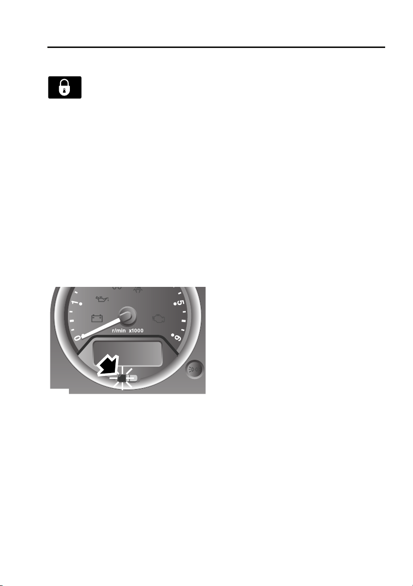
Alarm indicator
E85180
The alarm status is displayed by the indicator in
the speedometer.
• Indicator off - alarm disarmed.
• Indicator flashes rapidly for 10 seconds
when the remote lock button is pressed,
then adjusts to a slower frequency - the
alarm has been armed.
• If the indicator fails to adjust to a slower
frequency after the initial 10 second
period, the remote control battery needs
replacing.
• Indicator flashes rapidly when the alarm is
disarmed - the alarm has been triggered.
• Indicator flashes slowly - the engine is
immobilised, but the alarm is disarmed.
• Indicator illuminates (without flashing) for
10 seconds before adjusting to a slow
frequency flash - the driver's door is not
closed.
Engine immobilisation
Engine immobilisation prevents the engine
from being started without a valid key and
remote control and is activated whenever the
alarm is armed using the remote control. In
addition, the immobiliser activates
automatically under the following conditions:
• Thirty seconds after the starter switch has
been turned off and the driver's door is
opened.
• Five minutes after the starter switch is
turned off or after the alarm system is
disarmed (if the starter switch has not
been turned on).
Note: Details on how to deactivate engine
immobilisation are given later in this section.
See DISARMING THE ALARM (page 36).
35
Page 2
Alarm
DISARMING THE ALARM
When the vehicle is unlocked using
the remote control, the alarm is
automatically disabled and the
engine is remobilised. The hazard lamps will
flash once to indicate that the alarm is disabled.
Note: If the remote control is lost, damaged or
fails to operate, it is necessary to enter the
emergency key access code, to disarm the
alarm and deactivate engine immobilisation.
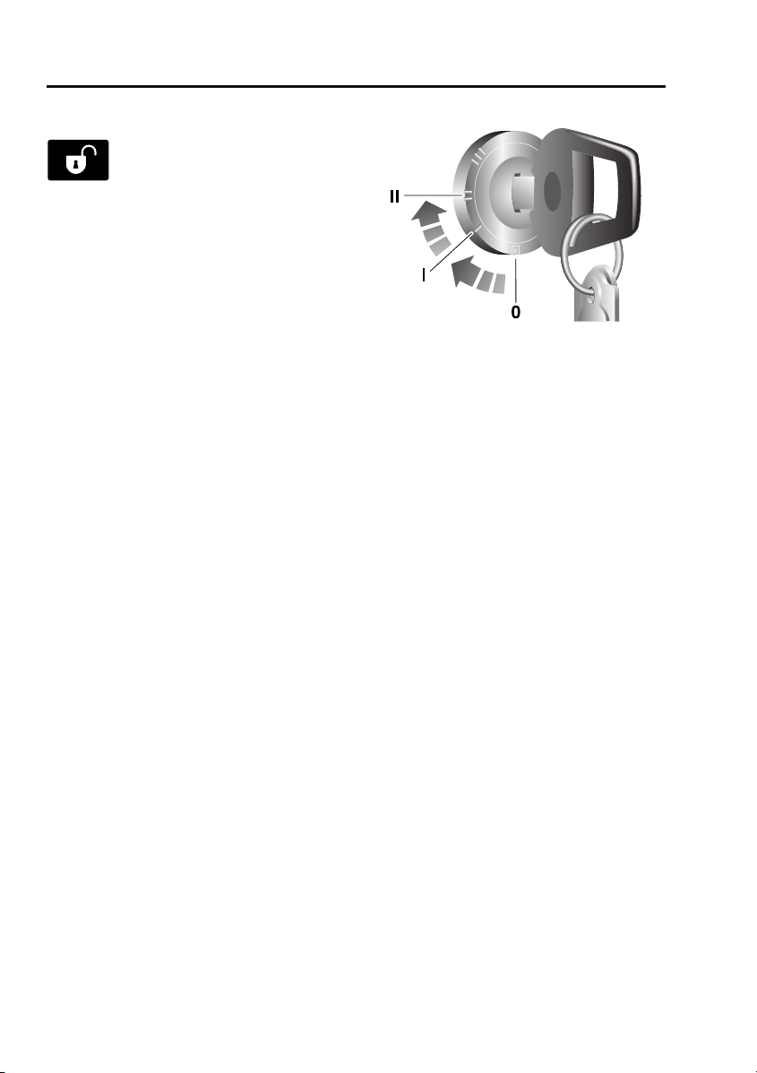
Deactivating engine immobilisation
Engine immobilisation is deactivated
automatically whenever the vehicle is unlocked
using the remote control. Engine
immobilisation is also deactivated when the
starter switch is turned to position II, provided
the remote control is on the same key ring as
the key and in close proximity to the switch.
If, however, the remote control is damaged, or
fails to operate, immobilisation can only be
deactivated by entering the emergency key
access code.
Emergency key access
Note: If the remote control cannot be used, it is
impossible to disarm the alarm in the normal
way. The alarm will sound (for 30 second
durations) as soon as a door is opened and will
continue until the code has been entered.
To deactivate engine immobilisation manually,
in the event of remote control failure, follow the
procedure below to enter the unique four digit
emergency key access code. The code for your
vehicle is recorded on the Security card.
E85179
1. Remove the remote control from the key
ring and keep it well away from the starter
switch while entering the code.
2. Unlock the driver's door using the key,
open the door and enter the vehicle. Shut
the driver's door.
3. Insert the key in the starter switch, turn
and hold the key in position II until the
alarm sounds. Then, turn off the starter
switch and open and close the driver's
door.
4. Turn the starter switch to position II the
required number of times to enter the first
digit of the code (if the digit is 4, turn the
key to position II and then back to position
0 four times).
5. Open and close the driver's door (this will
enter the first digit of the code).
6. Turn the starter switch to position II and
back to 0 the required number of times to
enter the second digit of the code, then
open and close the driver's door.
7. Turn the starter switch to position II and
back to 0 the required number of times to
enter the third digit of the code, then open
and close the driver's door.
36
Page 3

Alarm
8. Turn the starter switch to position II and
back to 0 the required number of times to
enter the fourth digit of the code, then
finally, open and close the driver's door
one more time.
If the code has been entered correctly, the
alarm indicator will extinguish, the alarm will
stop sounding and the engine can be started.
If an incorrect code has been entered:
If the code is entered incorrectly, the alarm
sounder will sound twice, the alarm indicator
will continue to illuminate and the engine will
fail to start. Before entering the code again,
turn the starter switch to position II and hold in
this position for five seconds.
After three failed entry attempts, the security
system invokes a delay period of 30 minutes,
during which the system will not accept further
attempts to enter a code.
Memorise the emergency key access code or
keep the Security card on your person, in case
of emergencies. Never leave the card in the
vehicle.
Deactivating the alarm when triggered
If the alarm has been triggered it can be
deactivated by pressing either of the remote
control buttons.
37
Page 4
Audio introduction
Audio introduction
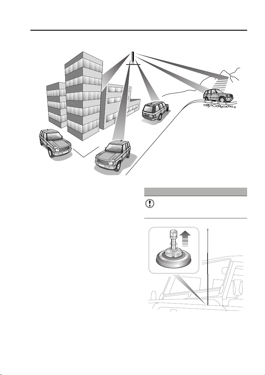
RADIO RECEPTION
E81779
Some interference is to be expected from time
to time during a journey. Occasionally it may be
necessary to retune the audio unit to offset the
effects of moving from one transmitter area to
another.
While Radio Data System (RDS) automatic
retuning helps to reduce the effects of signal
changes, some manual retuning may still be
required (especially for local stations) in areas
of weak reception.
FM Signals travel in a straight line so large
obstacles, such as tall buildings, can shield the
vehicle from the signal, causing distortion or
loss of reception (known as dead spots).
Distortion can also occur if FM signals received
directly from the transmitter, mix with signals
deflected by obstructions such as mountains,
hills and tall buildings. This is known as
multi-path distortion.
Note: Although distortion, interference and
lack of signal clarity are sometimes attributed
to a fault in the radio, this is rarely the case.
Radio aerial
CAUTION
The radio aerial should be fully lowered,
before the vehicle enters an automated
car wash.
E88514
Raise the aerial, as shown, to improve radio
reception.
153
Page 5

Audio system security
Audio system security
SECURITY CODE
The security code is entered into the head unit
during manufacture; it is not necessary to enter
the code during normal vehicle usage.
However, in the event of a battery reset, e.g.
subsequent to a flat battery or head unit
change, the head unit will prompt for a security
code.
Entering a security code
The vehicle is delivered to the user with a
security code card; the user must enter the
code using the numeric (radio preset) buttons
to resume operation of the head unit. For
example, if the code is 1234 the user must
press the number 1 button once, the number 2
button twice, the number 3 button three times
and the number 4 button four times followed
by a single press of the number 5 button to
complete the code input process.
In the event that the head unit code card is lost,
the user should seek advice from the dealer to
retrieve the code for their head unit. The user
will be required to produce some form of proof
that they are the rightful owner of the vehicle
e.g. the log book or a purchase receipt (if
bought second hand, for example) before the
dealer is authorised to issue the code. This
condition is imposed to prevent stolen head
units being used.
156
Page 6
Audio unit operation
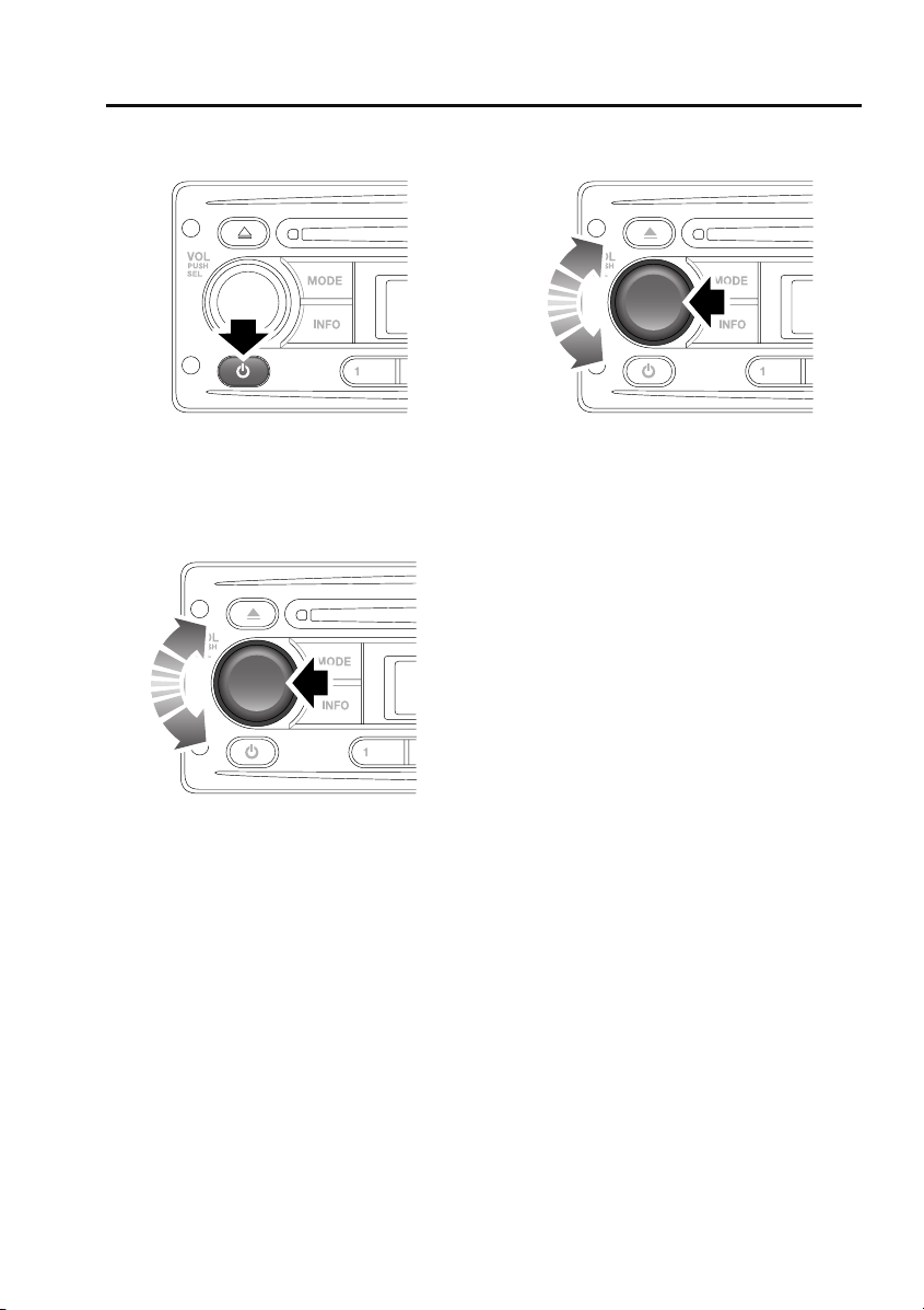
ON/OFF BUTTON
Audio unit operation
AUDIO CONTROL
E84868
Press the on/off button to switch the audio unit
on. Press again to switch off.
VOLUME CONTROL
E85374
Rotate the volume control to increase or
decrease the audio unit volume. The volume
can be set between 0 and 32.
Note: The audio unit can be used with the
engine off, but will be switched off
automatically after one hour.
Press the volume control to access and change
the settings on menus 1 and 2. See AUDIO
CONTROL (page 157).
E85374
You can change a number of settings using the
volume control.
Press and release (short press) the volume
control to access menu 1. Press and hold (long
press) the volume control to access the more
advanced settings on menu 2. Press the
volume control repeatedly to scroll through the
available menu options and then rotate the
volume control to change a setting. Press and
release the volume control to confirm a setting.
Note: If you do not press the volume control
for a period of three seconds, you will exit the
current menu automatically.
Settings menu 1 contains basic settings that
control sound quality or its distribution
between the speakers in the vehicle.
Bass response adjustment
1. Short press the volume control repeatedly
until BAS is displayed.
2. Rotate the volume control to increase or
decrease the bass level from –6 to +6.
Treble response adjustment
1. Short press the volume control repeatedly
until TRE is displayed.
2. Rotate the volume control to increase or
decrease the treble level from –6 to +6.
157
Page 7

Audio unit operation
Balance adjustment
1. Short press the volume control repeatedly
until BAL is displayed.
2. Rotate the volume control to adjust sound
level to the right (R) or left (L) of the
vehicle.
Fader adjustment
1. Short press the volume control repeatedly
until FAD is displayed.
2. Rotate the volume control to adjust the
sound level to the front (F) or rear (R) of
the vehicle.
Settings menu 2 contains more advanced
settings that you will not normally change, as
described below.
Traffic announcement (TA) volume
adjustment
You can adjust the volume level of traffic
announcements.
1. Long press the volume control and then
short press it repeatedly until TAVOL is
displayed.
2. Rotate the volume control to set the TA
volume level between 0 and 32. The default
setting is 10.
Note: This setting also applies to the volume of
PTY news announcements.
Alternative frequencies
As the audio unit receives information about
the frequencies being used by nearby
transmitters, it can choose the strongest signal
for the selected station. With the Alternative
Frequencies (AF) feature enabled, you will not
need to retune the radio as you drive between
different transmitter areas.
1. Long press the volume control and then
short press it repeatedly until AF is
displayed.
2. Rotate the volume control to turn the AF
setting on or off.
Note: The AF switch status will be displayed
briefly and the AF indicator is displayed if AF is
active.
Regional mode
As you drive into different radio reception
areas, the Radio Data System (RDS)
automatically retunes the audio unit to the
strongest signal. Regional mode is an RDS
feature that stops the audio unit from tuning to
another local radio station with a stronger
signal. With this feature enabled, your selected
local radio station will remain tuned.
1. Long press the volume control and then
short press it repeatedly until REG is
displayed.
2. Rotate the volume control to turn the REG
setting on or off.
Loudness setting
You can turn the loudness setting on or off.
1. Long press the volume control and then
short press it repeatedly until LOUD is
displayed.
2. Rotate the volume control to turn the
setting on or off.
158
Page 8

Audio unit operation
Audible beeps
You can choose to change when audible beeps
are heard.
1. Long press the volume control and then
short press it repeatedly until BEEP is
displayed.
2. Rotate the volume control to choose from
the following options: All (beep on every
button press), 2nd (beep on long button
press only), Off (no beeps).
Default volume adjustment
You can adjust the volume level at which the
audio unit is set when it is switched on (default
volume).
1. Long press the volume control and then
short press it repeatedly until D-Vol is
displayed.
2. Rotate the volume control to set the
volume level between 0 and 32. The default
setting is 10.
Telephone setting
If you choose to fit a hands-free telephone to
the vehicle, you can switch on this setting to
ensure that the audio unit is muted when a call
is made or received.
1. Long press the volume control and then
short press it repeatedly until TEL is
displayed.
2. Rotate the volume control to turn the
setting on or off.
Area settings
You only need to change this setting if you
intend to move the vehicle to another
continent, for example from Europe to Asia.
1. Long press the volume control and then
short press it repeatedly until AREA is
displayed.
2. Rotate the volume control to choose from
the following options: Latin (Central and
South America), Asia, USA and Europe.
Long wave
You can use this setting to enable or disable
Long Wave.
1. Long press the volume control and then
short press it repeatedly until LW is
displayed.
2. Rotate the volume control to turn the
setting on or off.
WAVEBAND BUTTON
To select a waveband, press and release the
AM/FM button. Repeated presses will scroll
through FM1, FM2, FM3, MW1, MW2 and LW
(if available).
159
Page 9
Audio unit operation
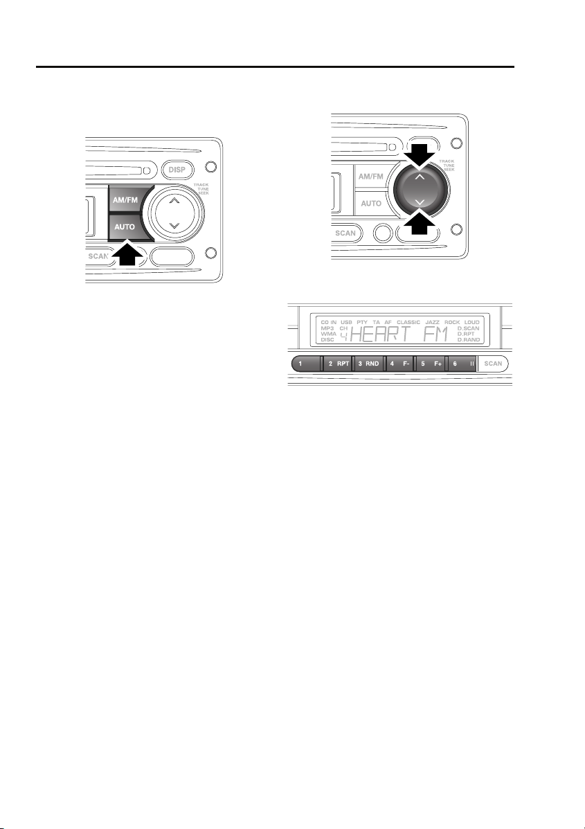
AUTOSTORE CONTROL
Autostoring radio stations
E84816
To autostore stations, select the required
waveband, then press the AUTO button. The
word SEARCH will be shown in the information
display and the six stations with the strongest
signals will be located and stored under the
preset numbers in the order in which they are
found.
To recall an autostored station, press and
release the required preset number.
STATION PRESET BUTTONS
E84859
E84817
To store a station, press and release either the
up or down arrow on the search button to find
the next available station. If you want to tune to
a station manually, then press and hold either
the up or down arrow on the search button and
then use the search button to tune into the
frequency you require. Having tuned to the
desired station, press and hold the preset
number under which you would like the station
stored.
The audio output will be muted when the
button is pressed and an audible beep will
indicate that the station has been stored.
To access stored stations, press and release
the required preset number.
160
Page 10
Audio unit operation
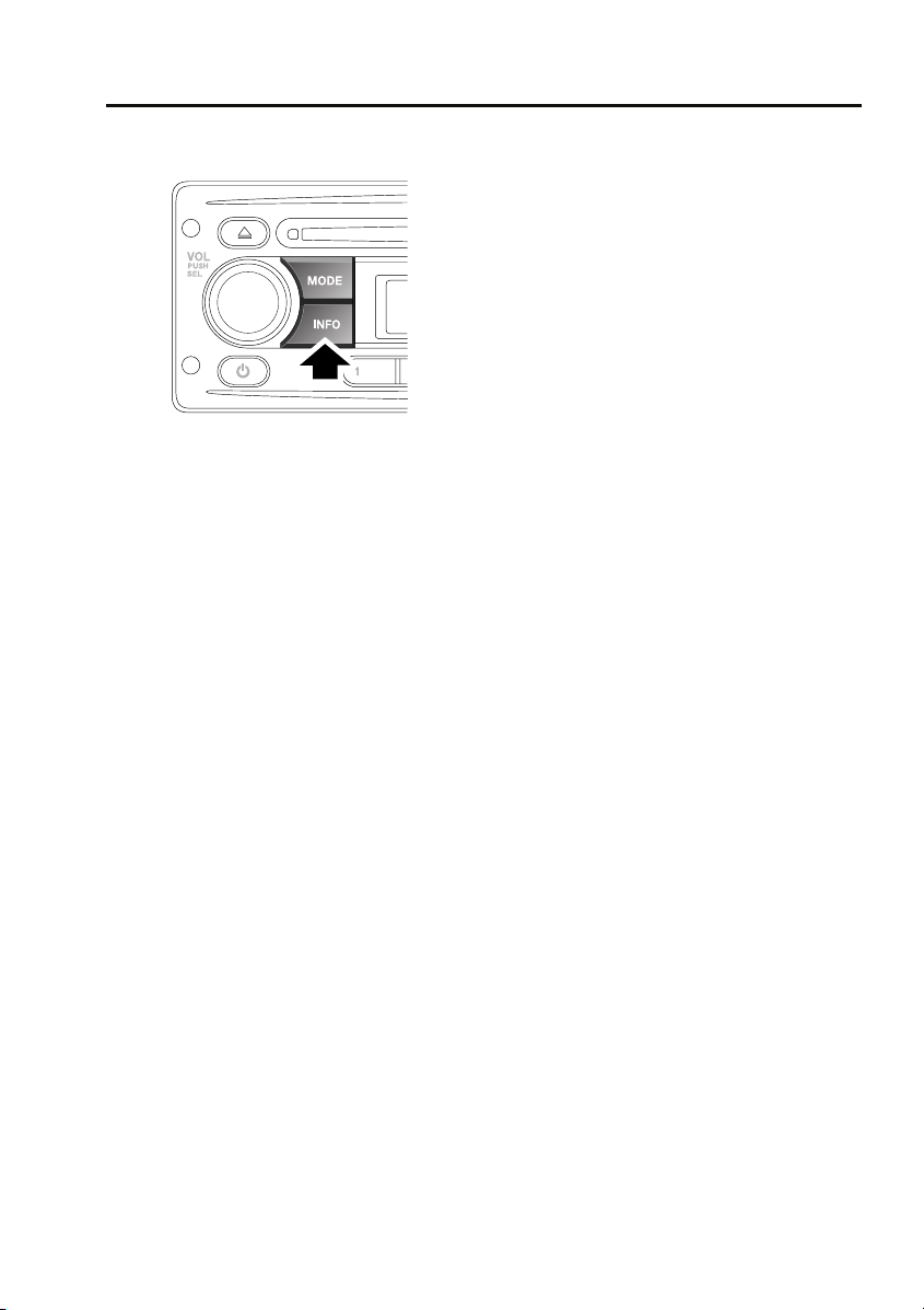
TRAFFIC INFORMATION CONTROL
E85375
The Information function locates and plays
local travel announcements and news bulletins.
Traffic announcements
Short press the INFO button to toggle traffic
announcements on or off (TA is displayed on
the screen). As soon as a traffic announcement
is detected, radio reception or CD play will be
interrupted for the duration of the
announcement. At the end of the traffic
announcement, radio or CD play will resume.
During a traffic announcement, you can cancel
it and return to the station you were previously
listening to, by short pressing the INFO button.
This does not turn off the traffic announcement
function, only the current announcement.
PTY news announcements
Long press the INFO button to toggle PTY
news announcements on or off (PTY is
displayed on the screen). As soon as a PTY
news announcement is detected, radio
reception or CD play will be interrupted for the
duration of the announcement. At the end of
the news announcement, radio or CD play will
resume.
During a news announcement, you can cancel
it and return to the station you were previously
listening to, by long pressing the INFO button.
This does not turn off the PTY news function,
only the current announcement.
161
Page 11
Audio unit overview
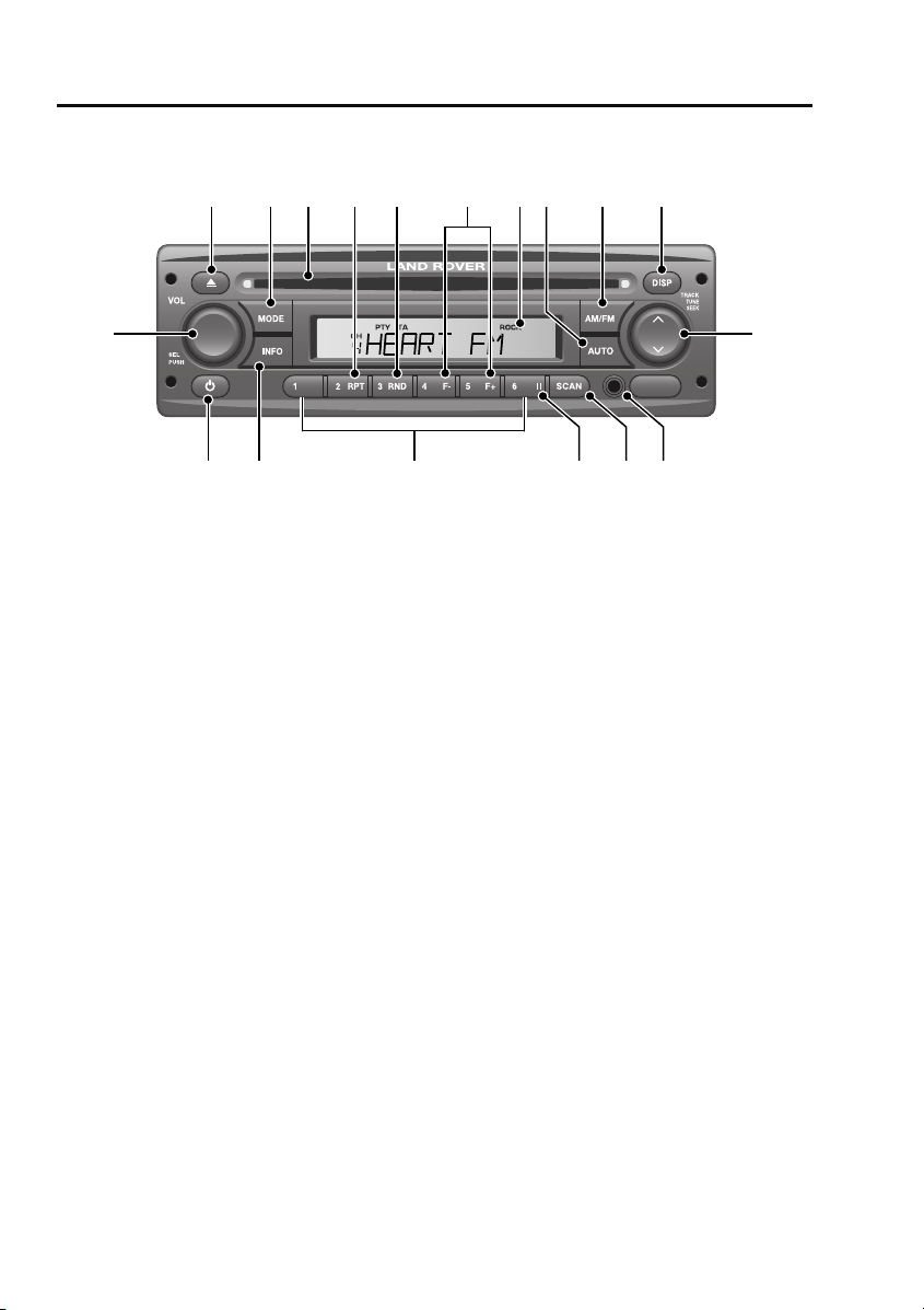
AUDIO UNIT OVERVIEW
Audio unit overview
1 2 4 53 87 9 10
18
E84603
1. Compact disc eject button
2. MODE button
• Press to scroll through CD, Tuner and
Auxiliary modes (if available).
3. Compact disc entry slot
4. RPT button
• Press to repeat the current CD track.
5. RND button
• Press to play CD tracks in a random
order.
6. F–/F+ buttons
• Press to move to the previous (F-) or
next (F+) folder of an MP3 data disc.
7. Information display screen
8. AUTO button
• Press and release to store the six
strongest stations automatically.
• Press once, twice or three times to
activate searching functions for MP3
data discs.
9. AM/FM button
• Press to select AM or FM wavebands.
6
11
15 14 13 121617
10. DISP button
• Press to scroll through information
displayed on the screen.
11. Search button: press the up or down arrow
• Short press to search up or down for
radio stations.
• Long press to activate manual tuning of
radio stations.
• Short press to find next or previous CD
track.
• Long press to fast forward or rewind
through current CD track.
12. Auxiliary audio input socket (if function is
available)
13. SCAN button
• Press to search available preset radio
stations (1-6); press again to select a
station.
• Press to search all CD tracks; press
again to play a track.
14. Pause button
• Press to pause a CD track.
154
Page 12

Audio unit overview
15. Keypad
• Short press to access any preset radio
stations.
• Long press to store the current radio
station.
16. INFO button
• Short press for traffic announcements
(TA).
• Long press for news broadcast function
(PTY).
17. On/off button
18. Volume control
• Rotate to adjust volume level.
• Short press for settings menu 1.
• Long press for settings menu 2.
155
Page 13
Auxiliary input (AUX IN) socket
Auxiliary input (AUX IN) socket
AUXILIARY INPUT SOCKET
WARNINGS
Make sure that any auxiliary devices are
stored securely while the vehicle is in
motion. Any loose objects can present a
serious hazard during sudden manoeuvres,
emergency braking or an accident.
Do not place any item connected to the
auxiliary input socket or the auxiliary
power socket on the vehicle’s seats, carpets,
or other upholstery. The heat generated by
these devices may cause damage to the
upholstery, or in extreme cases, a vehicle fire.
Do not leave any auxiliary input devices
connected while the vehicle is left
unattended. There is a risk of heat damage or
fire, in addition to the risk of theft.
CAUTION
Read the manufacturer's instructions for
any device before it is connected to the
vehicle's audio system. Keep to any
instructions about connection and operation
and make sure that the device is suitable.
Failure to do so may result in damage to the
vehicle's audio system or the auxiliary device.
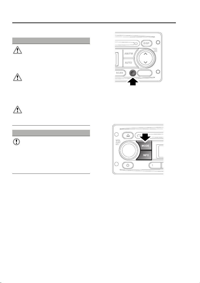
AUX (Auxiliary Input) mode allows extra
equipment to be connected to the vehicle's
audio system. Items such as a personal stereo,
MP3 player, hand-held navigation unit etc., can
be plugged in to the vehicle's audio system.
Note: The volume levels and sound quality
available from devices connected to the
auxiliary inputs may vary widely. If the
connected audio device is equipped with a line
out socket as well as a headphone socket, the
line out socket should be used.
E84604
Auxiliary audio devices are connected via the
3.5 mm stereo jack socket. If fitted, the
auxiliary audio socket is situated at the bottom
right of the audio unit.
Auxiliary mode
E85379
To listen to an auxiliary input source, switch on
and connect the device to the jack socket.
Press and release the MODE button repeatedly
until AUX mode is displayed on the screen. The
audio unit will start playback automatically.
168
Page 14

Index
A
ABS driving hints . . . . . . . . . . . . . . . . . . . 85
Accessories. . . . . . . . . . . . . . . . . . . . . . . . 28
Adjusting the windscreen washer jets . . . . 61
Blocked jets . . . . . . . . . . . . . . . . . . . . . 61
Air vents . . . . . . . . . . . . . . . . . . . . . . . . . . 70
Arming the alarm . . . . . . . . . . . . . . . . . . . 35
Alarm indicator . . . . . . . . . . . . . . . . . . . 35
Engine immobilisation . . . . . . . . . . . . . 35
Ashtray . . . . . . . . . . . . . . . . . . . . . . . . . . . 75
Audio control. . . . . . . . . . . . . . . . . . . . . . 157
Alternative frequencies . . . . . . . . . . . . 158
Area settings. . . . . . . . . . . . . . . . . . . . 159
Audible beeps . . . . . . . . . . . . . . . . . . . 159
Balance adjustment. . . . . . . . . . . . . . . 158
Bass response adjustment . . . . . . . . . 157
Default volume adjustment. . . . . . . . . 159
Fader adjustment . . . . . . . . . . . . . . . . 158
Long wave . . . . . . . . . . . . . . . . . . . . . 159
Loudness setting . . . . . . . . . . . . . . . . 158
Regional mode . . . . . . . . . . . . . . . . . . 158
Telephone setting . . . . . . . . . . . . . . . . 159
Traffic announcement (TA) volume
adjustment . . . . . . . . . . . . . . . . . . . 158
Treble response adjustment . . . . . . . . 157
Audio unit overview. . . . . . . . . . . . . . . . . 154
Autostore control . . . . . . . . . . . . . . . . . . 160
Autostoring radio stations . . . . . . . . . 160
Auxiliary input socket . . . . . . . . . . . . . . . 168
Auxiliary mode . . . . . . . . . . . . . . . . . . 168
B
Battery care . . . . . . . . . . . . . . . . . . . . . . . 115
Battery charging . . . . . . . . . . . . . . . . . . . 118
Battery warning symbols. . . . . . . . . . . . . 115
Bonnet lock . . . . . . . . . . . . . . . . . . . . . . . 104
Booster cables. . . . . . . . . . . . . . . . . . . . . 117
Booster cushions . . . . . . . . . . . . . . . . . . . 50
Brake fluid check. . . . . . . . . . . . . . . . . . . 111
Checking the fluid level . . . . . . . . . . . . 111
Topping up the fluid . . . . . . . . . . . . . . 111
Brakes
Principle of operation . . . . . . . . . . . . . . 85
Bulb changing . . . . . . . . . . . . . . . . . . . . . . 53
Bulb specification chart. . . . . . . . . . . . . . . 59
C
Car wash . . . . . . . . . . . . . . . . . . . . . . . . . . 98
Changing a bulb . . . . . . . . . . . . . . . . . . . . . 53
General information . . . . . . . . . . . . . . . . 53
Headlamp unit bulbs . . . . . . . . . . . . . . . 55
High level brake lamp. . . . . . . . . . . . . . . 57
Interior lamp bulbs. . . . . . . . . . . . . . . . . 58
Number plate lamps. . . . . . . . . . . . . . . . 57
Rear lamp bulbs. . . . . . . . . . . . . . . . . . . 56
Removing the headlamp unit . . . . . . . . . 54
Side repeater lamp . . . . . . . . . . . . . . . . . 58
Changing a fuse . . . . . . . . . . . . . . . . . . . . 137
Changing a road wheel . . . . . . . . . . . . . . . 128
Changing a wheel. . . . . . . . . . . . . . . . . 134
Jack and tool kit. . . . . . . . . . . . . . . . . . 128
Locking wheel nuts . . . . . . . . . . . . . . . 130
Operating the bottle jack . . . . . . . . . . . 131
Positioning the bottle jack . . . . . . . . . . 132
Positioning the pillar jack . . . . . . . . . . . 133
Spare wheel . . . . . . . . . . . . . . . . . . . . . 129
Wheel changing safety . . . . . . . . . . . . . 130
Changing the vehicle battery . . . . . . . . . . 119
Battery disposal . . . . . . . . . . . . . . . . . . 120
Disconnecting . . . . . . . . . . . . . . . . . . . 119
Effects of disconnecting. . . . . . . . . . . . 120
Refitting . . . . . . . . . . . . . . . . . . . . . . . . 120
Replacement batteries . . . . . . . . . . . . . 120
Changing the wiper blades . . . . . . . . . . . . . 62
Charging the vehicle battery . . . . . . . . . . . 118
Checking the wiper blades . . . . . . . . . . . . . 62
Child safety locks . . . . . . . . . . . . . . . . . . . . 50
Child seats . . . . . . . . . . . . . . . . . . . . . . . . . 49
Child restraint check list. . . . . . . . . . . . . 49
Cigar lighter . . . . . . . . . . . . . . . . . . . . . . . . 74
Cleaning the exterior. . . . . . . . . . . . . . . . . . 98
Washing the vehicle . . . . . . . . . . . . . . . . 98
Cleaning the interior . . . . . . . . . . . . . . . . . . 99
Carpets and fabrics . . . . . . . . . . . . . . . 100
Instrument pack, clock, and audio
equipment . . . . . . . . . . . . . . . . . . . . 100
Plastic and cloth. . . . . . . . . . . . . . . . . . . 99
Seat belts . . . . . . . . . . . . . . . . . . . . . . . 100
Clock
Analogue . . . . . . . . . . . . . . . . . . . . . . . . 74
169
Page 15

Index
Clutch fluid check . . . . . . . . . . . . . . . . . . 112
Checking the fluid level . . . . . . . . . . . . 112
Topping up the fluid . . . . . . . . . . . . . . 112
Compact disc
Ejecting . . . . . . . . . . . . . . . . . . . . . . . . 163
Error messages. . . . . . . . . . . . . . . . . . 162
Fast forward/reverse . . . . . . . . . . . . . . 165
Loading. . . . . . . . . . . . . . . . . . . . . . . . 162
MP3 file playback . . . . . . . . . . . . . . . . 166
Pause . . . . . . . . . . . . . . . . . . . . . . . . . 164
Playback . . . . . . . . . . . . . . . . . . . . . . . 164
Random track selection . . . . . . . . . . . 165
Repeat tracks . . . . . . . . . . . . . . . . . . . 165
Track scanning . . . . . . . . . . . . . . . . . . 165
Track selection . . . . . . . . . . . . . . . . . . 164
Coolant check . . . . . . . . . . . . . . . . . . . . . 108
Cup holders. . . . . . . . . . . . . . . . . . . . . . . . 75
D
Dimensions . . . . . . . . . . . . . . . . . . . . . . . 148
Direction indicators . . . . . . . . . . . . . . . . . . 53
Disarming the alarm . . . . . . . . . . . . . . . . . 36
Deactivating engine immobilisation . . . 36
Deactivating the alarm when triggered . 37
Driving after a collision . . . . . . . . . . . . . . 142
Before starting or driving . . . . . . . . . . 142
When driving. . . . . . . . . . . . . . . . . . . . 142
E
Economical driving . . . . . . . . . . . . . . . . . . 88
Driving tips for economy. . . . . . . . . . . . 88
Maintenance and fuel economy. . . . . . . 88
Electric windows . . . . . . . . . . . . . . . . . . . . 63
Engine compartment overview . . . . . . . . 105
Engine coolant check. . . . . . . . . . . . . . . . 108
Checking the coolant level. . . . . . . . . . 108
Topping up the coolant . . . . . . . . . . . . 108
Engine oil check . . . . . . . . . . . . . . . . . . . 107
Checking the oil level . . . . . . . . . . . . . 107
Engine oil specification . . . . . . . . . . . . 108
Topping up the oil . . . . . . . . . . . . . . . . 108
Engine specifications. . . . . . . . . . . . . . . . 146
Essential towing checks . . . . . . . . . . . . . . 95
Event data recording . . . . . . . . . . . . . . . . . 27
Exterior mirrors . . . . . . . . . . . . . . . . . . . . . 64
Folding the mirror body . . . . . . . . . . . . . 64
Positioning the mirror for towing . . . . . . 64
F
Fastening the seat belts . . . . . . . . . . . . . . . 47
Releasing the seat belts . . . . . . . . . . . . . 47
Filling station information . . . . . . . . . . . . . . 24
Engine coolant specification. . . . . . . . . . 25
Engine oil specification. . . . . . . . . . . . . . 25
Fuel filler cap . . . . . . . . . . . . . . . . . . . . . 24
Fuel and refuelling
Technical specifications . . . . . . . . . . . . . 91
Fuel consumption . . . . . . . . . . . . . . . . . . . . 91
Fuel quality . . . . . . . . . . . . . . . . . . . . . . . . . 89
Sulphur content . . . . . . . . . . . . . . . . . . . 89
Fuse box locations . . . . . . . . . . . . . . . . . . 137
Main fuse box. . . . . . . . . . . . . . . . . . . . 137
Secondary fuse box . . . . . . . . . . . . . . . 137
Fuse specification chart
Fuse positions and specifications. . . . . 138
Main fuse box. . . . . . . . . . . . . . . . . . . . 138
Secondary fuse box . . . . . . . . . . . . . . . 140
G
General information on radio frequencies. . 30
H
Handbrake . . . . . . . . . . . . . . . . . . . . . . . . . 86
Hazard warning flashers . . . . . . . . . . . 52, 141
Head restraints . . . . . . . . . . . . . . . . . . . . . . 41
Lowering . . . . . . . . . . . . . . . . . . . . . . . . 41
Raising . . . . . . . . . . . . . . . . . . . . . . . . . . 41
Headlamp levelling . . . . . . . . . . . . . . . . . . . 52
Vehicles fitted with front seats only . . . . 52
Heated seats . . . . . . . . . . . . . . . . . . . . . . . . 45
Hints on driving with ABS. . . . . . . . . . . . . . 85
ABS and off-road driving . . . . . . . . . . . . 86
ABS warning indicator . . . . . . . . . . . . . . 85
I
Inspecting safety system components . . . 142
Instrument panel overview . . . . . . . . . . . . . 65
Instrument panel . . . . . . . . . . . . . . . . . . 65
Interior lamps . . . . . . . . . . . . . . . . . . . . . . . 53
Interior mirror. . . . . . . . . . . . . . . . . . . . . . . 64
170
Page 16

Index
J
Jump starting . . . . . . . . . . . . . . . . . . . . . 117
K
Keys . . . . . . . . . . . . . . . . . . . . . . . . . . . . . 30
L
Lashing points. . . . . . . . . . . . . . . . . . . . . 143
Levelling . . . . . . . . . . . . . . . . . . . . . . . . . . 94
Lighting control. . . . . . . . . . . . . . . . . . . . . 51
Main beam . . . . . . . . . . . . . . . . . . . . . . 51
Main lighting switch . . . . . . . . . . . . . . . 51
Load carriers . . . . . . . . . . . . . . . . . . . . . . . 93
Load carrying
General information . . . . . . . . . . . . . . . 92
Loading compact discs . . . . . . . . . . . . . . 162
Locking and unlocking . . . . . . . . . . . . . . . 33
Locking and unlocking from inside the
vehicle . . . . . . . . . . . . . . . . . . . . . . . 33
Mislock . . . . . . . . . . . . . . . . . . . . . . . . . 34
Taildoor . . . . . . . . . . . . . . . . . . . . . . . . 33
Tailgate . . . . . . . . . . . . . . . . . . . . . . . . . 34
Luggage anchor points . . . . . . . . . . . . . . . 92
M
Maintenance
General information . . . . . . . . . . . . . . 101
Technical specifications . . . . . . . . . . . 114
Manual climate control . . . . . . . . . . . . . . . 71
Controls . . . . . . . . . . . . . . . . . . . . . . . . 71
Heated screens . . . . . . . . . . . . . . . . . . . 72
Manual seats . . . . . . . . . . . . . . . . . . . . . . . 39
Front seat base removal . . . . . . . . . . . . 39
Manual transmission. . . . . . . . . . . . . . . . . 81
MP3 file playback
Searching an MP3 data disc . . . . . . . . 167
O
Oil check . . . . . . . . . . . . . . . . . . . . . . . . . 107
On/off button. . . . . . . . . . . . . . . . . . . . . . 157
Opening and closing the bonnet . . . . . . . 104
Closing the bonnet . . . . . . . . . . . . . . . 104
Opening the bonnet . . . . . . . . . . . . . . 104
P
Parking brake . . . . . . . . . . . . . . . . . . . . . . . 86
Applying the parking brake . . . . . . . . . . 86
Parking on a slope . . . . . . . . . . . . . . . . . 86
Releasing the parking brake. . . . . . . . . . 87
Power steering fluid check . . . . . . . . . . . . 110
Checking the fluid level . . . . . . . . . . . . 110
Topping up the fluid. . . . . . . . . . . . . . . 110
Principle of operation
Brake pads . . . . . . . . . . . . . . . . . . . . . . . 85
Seat belt checks . . . . . . . . . . . . . . . . . . . 47
Seat belt safety. . . . . . . . . . . . . . . . . . . . 46
Seat belts . . . . . . . . . . . . . . . . . . . . . . . . 46
Wet conditions. . . . . . . . . . . . . . . . . . . . 85
Q
Quick start . . . . . . . . . . . . . . . . . . . . . . . . . . 7
Audio system controls . . . . . . . . . . . . . . 22
Battery and tool kit. . . . . . . . . . . . . . . . . 22
CD operation . . . . . . . . . . . . . . . . . . . . . 23
Climate control. . . . . . . . . . . . . . . . . . . . 12
Engine starting and stopping . . . . . . . . . . 8
Exterior lamps master switch. . . . . . . . . 20
Facia. . . . . . . . . . . . . . . . . . . . . . . . . . . . 14
Front seats . . . . . . . . . . . . . . . . . . . . . . . . 9
Instrument pack. . . . . . . . . . . . . . . . . . . 16
Keys and remote control . . . . . . . . . . . . . 7
Parking brake. . . . . . . . . . . . . . . . . . . . . 19
Pickup tailgate . . . . . . . . . . . . . . . . . . . . . 8
Radio operation . . . . . . . . . . . . . . . . . . . 23
Seat belts and Child restraints . . . . . . . . 11
Sound settings. . . . . . . . . . . . . . . . . . . . 22
Steering column levers . . . . . . . . . . . . . 19
Third-row seats . . . . . . . . . . . . . . . . . . . 10
Transfer gearbox . . . . . . . . . . . . . . . . . . 20
Warning indicators (attention) . . . . . . . . 18
Warning indicators (information). . . . . . 18
Windows . . . . . . . . . . . . . . . . . . . . . . . . 11
R
Radio reception . . . . . . . . . . . . . . . . . . . . 153
Radio aerial . . . . . . . . . . . . . . . . . . . . . 153
Rear fog lamps . . . . . . . . . . . . . . . . . . . . . . 51
Rear seats . . . . . . . . . . . . . . . . . . . . . . . . . 41
Folding the rear seats. . . . . . . . . . . . . . . 42
Raising the rear seats . . . . . . . . . . . . . . 43
171
Page 17

Index
Rear window wiper and washers. . . . . . . . 61
Recommended towing weights . . . . . . . . . 95
Refitting the roof . . . . . . . . . . . . . . . . . . . . 77
Refuelling . . . . . . . . . . . . . . . . . . . . . . . . . 90
Fuel filler cap. . . . . . . . . . . . . . . . . . . . . 90
Fuel filling . . . . . . . . . . . . . . . . . . . . . . . 90
Remote control . . . . . . . . . . . . . . . . . . . . . 31
Repairing minor paint damage . . . . . . . . 100
Roof racks and load carriers . . . . . . . . . . . 93
Roof rack safety . . . . . . . . . . . . . . . . . . 93
Running out of fuel . . . . . . . . . . . . . . . . . . 89
Running-in . . . . . . . . . . . . . . . . . . . . . . . . 88
S
Safety . . . . . . . . . . . . . . . . . . . . . . . . . . . . 27
Safety precautions. . . . . . . . . . . . . . . . . . . 89
Seat belts
Principle of operation . . . . . . . . . . . . . . 46
Security code. . . . . . . . . . . . . . . . . . . . . . 156
Sitting in the correct position . . . . . . . . . . 38
Sliding windows . . . . . . . . . . . . . . . . . . . . 63
Snow chains . . . . . . . . . . . . . . . . . . . . . . 135
Starting a diesel engine . . . . . . . . . . . . . . . 80
Station preset buttons. . . . . . . . . . . . . . . 160
Steps . . . . . . . . . . . . . . . . . . . . . . . . . . . . . 76
Storage compartments . . . . . . . . . . . . . . . 76
Cubby box. . . . . . . . . . . . . . . . . . . . . . . 76
Sun visors . . . . . . . . . . . . . . . . . . . . . . . . . 74
Sunroof . . . . . . . . . . . . . . . . . . . . . . . . . . . 72
Opening and closing . . . . . . . . . . . . . . . 72
Removing the sunroof . . . . . . . . . . . . . 73
T
Technical specifications
. . . . . . . . . . . . . . . . . . . . . . . . . . . . . . 136
Capacities . . . . . . . . . . . . . . . . . . . . . . 114
Fuel consumption . . . . . . . . . . . . . . . . . 91
Fuel specification . . . . . . . . . . . . . . . . . 91
Lubricants and fluids . . . . . . . . . . . . . 114
Transmission fluids and capacities . . . . 84
Tow bar . . . . . . . . . . . . . . . . . . . . . . . . . . . 96
Tow bar dimensions . . . . . . . . . . . . . . . 96
Tow bar mounting points . . . . . . . . . . . 97
Towing a trailer . . . . . . . . . . . . . . . . . . . . . 94
Trailer electrical connection . . . . . . . . . 94
Towing points . . . . . . . . . . . . . . . . . . . . . . 143
Front and rear towing eyes. . . . . . . . . . 143
Towing the vehicle on four wheels . . . . . . 143
Towing procedure . . . . . . . . . . . . . . . . 144
Traffic information control . . . . . . . . . . . . 161
PTY news announcements . . . . . . . . . . 161
Traffic announcements. . . . . . . . . . . . . 161
Transfer gearbox. . . . . . . . . . . . . . . . . . . . . 81
High range . . . . . . . . . . . . . . . . . . . . . . . 81
Low range . . . . . . . . . . . . . . . . . . . . . . . 81
Neutral . . . . . . . . . . . . . . . . . . . . . . . . . . 82
The differential lock . . . . . . . . . . . . . . . . 82
Using the transfer gearbox . . . . . . . . . . . 82
Transmission
Technical specifications . . . . . . . . . . . . . 84
Transporting the vehicle . . . . . . . . . . . . . . 143
Type approvals . . . . . . . . . . . . . . . . . . . . . 151
Declarations of conformity . . . . . . . . . . 151
Tyre care. . . . . . . . . . . . . . . . . . . . . . . . . . 123
Age degradation . . . . . . . . . . . . . . . . . . 124
Directional tyres . . . . . . . . . . . . . . . . . . 125
Flat spots . . . . . . . . . . . . . . . . . . . . . . . 127
Pressure compensation for ambient
temperature changes . . . . . . . . . . . . 127
Punctured tyres . . . . . . . . . . . . . . . . . . 124
Replacement tyres . . . . . . . . . . . . . . . . 125
Tyre checks . . . . . . . . . . . . . . . . . . . . . 124
Tyre pressures . . . . . . . . . . . . . . . . . . . 126
Tyre wear . . . . . . . . . . . . . . . . . . . . . . . 123
Tyre glossary . . . . . . . . . . . . . . . . . . . . . . 135
Terms used . . . . . . . . . . . . . . . . . . . . . 135
U
Using booster cables . . . . . . . . . . . . . . . . 117
Disconnecting the cables . . . . . . . . . . . 118
Using seat belts during pregnancy . . . . . . . 48
Using snow chains . . . . . . . . . . . . . . . . . . 135
Using the key . . . . . . . . . . . . . . . . . . . . . . . 30
Using the remote control . . . . . . . . . . . . . . 31
Locking . . . . . . . . . . . . . . . . . . . . . . . . . 31
Remote battery. . . . . . . . . . . . . . . . . . . . 31
Remote control. . . . . . . . . . . . . . . . . . . . 31
Unlocking . . . . . . . . . . . . . . . . . . . . . . . . 31
Using winter tyres. . . . . . . . . . . . . . . . . . . 128
172
Page 18

Index
V
Vehicle identification number (VIN). . . . . 145
Vehicle identification plate. . . . . . . . . . . . 145
Vents. . . . . . . . . . . . . . . . . . . . . . . . . . . . . 70
VIN . . . . . . . . . . . . . . . . . . . . . . . . . . . . . 145
Volume control . . . . . . . . . . . . . . . . . . . . 157
W
Warning lamps and indicators. . . . . . . . . . 67
Anti-lock braking system - Amber . . . . 68
Battery charging - Red . . . . . . . . . . . . . 67
Brake systems - Red/Amber . . . . . . . . . 68
Check engine - Amber. . . . . . . . . . . . . . 67
Differential lock - Amber . . . . . . . . . . . . 69
Direction indicators - Green . . . . . . . . . 68
Glow plug - Amber . . . . . . . . . . . . . . . . 67
Hazard warning lamps . . . . . . . . . . . . . 68
Headlamp main beam - Blue . . . . . . . . . 68
Heated rear screen - Amber . . . . . . . . . 69
Low fuel - Amber . . . . . . . . . . . . . . . . . 69
Low oil pressure - Red . . . . . . . . . . . . . 67
Over-speed warning - Amber (Gulf states
only). . . . . . . . . . . . . . . . . . . . . . . . . 69
Rear fog lamp - Amber . . . . . . . . . . . . . 69
Seat belt - Red . . . . . . . . . . . . . . . . . . . 67
Side lamps on - Green . . . . . . . . . . . . . 68
Traction control - Amber. . . . . . . . . . . . 69
Trailer direction indicators - Green . . . . 68
Washer fluid check . . . . . . . . . . . . . . . . . 113
Topping up the fluid . . . . . . . . . . . . . . 113
Washing . . . . . . . . . . . . . . . . . . . . . . . . . . 98
Waveband button . . . . . . . . . . . . . . . . . . 159
Weights. . . . . . . . . . . . . . . . . . . . . . . . . . 146
Wheels and tyres
General information . . . . . . . . . . . . . . 121
Technical specifications . . . . . . . . . . . 136
Windscreen washers . . . . . . . . . . . . . . . . . 60
Windscreen wipers . . . . . . . . . . . . . . . . . . 60
Wiper operation . . . . . . . . . . . . . . . . . . 60
173
Page 19
Child safety
Child safety
CHILD SEATS
WARNINGS
Crash statistics show that children are
safest when properly restrained on the
rear seat.
Do not use a forward facing child seat
until the child using it is above the
minimum weight of 9 kg (20 lb.) and able to sit
up unaided. Up to the age of two, a child's
spine and neck are not sufficiently developed
to avoid injury in a frontal impact.
Do not allow a baby or infant to be held
or carried on the lap. The force of a
crash can increase effective body weight by as
much as thirty times, making it impossible to
hold onto the child. Children typically require
the use of a booster seat appropriate to their
age and size, thereby enabling the seat belts to
be properly fitted, reducing the risk of injury in
a crash. Children could be endangered in a
crash if their child restraints are not properly
secured in the vehicle.
Do not use a child seat that hooks over
the seat back. This type of seat cannot
be satisfactorily secured and is unlikely to be
safe for your child.
It is very important for all infants and children
under 12 years of age to be restrained in a
suitable child safety seat appropriate to their
age and size.
Child restraint check list
Every time a child travels in the vehicle observe
the following:-
• Use appropriate child restraints.
• Carefully follow the restraint system
manufacturers instructions.
• Adjust the harnesses for every child on
every trip.
• Ensure that all slack is removed from the
adult seatbelt.
• Always check the security of the child
restraint.
• Do not dress a child in bulky clothing, or
place any objects/padding between the
child and the restraint.
• Regularly check the fit and condition of
child restraints. If the fit is poor, or
wear/damage is visible replace the
restraint immediately.
• Set a good example - always wear your
seat belt.
Note: The information contained in the
following table may not be applicable to all
countries. If you are in any doubt regarding the
type and fitment of child seats seek advice from
your Land Rover Dealer/Authorised Repairer.
49
Page 20
Child safety seating and positions
Mass group 0 = Up to 10 kg
(22 lb)
Seating
positions
Front
passenger
Second-row
seats
Third-row
seats
UU UUU
UU UUU
UU UUU
0+ = Up to 13 kg
Child safety
I = 9-18 kg
(29 lb)
(20-40 lb)
II = 15-25 kg
(40-67 lb)
III = 25-36 kg
(67-80 lb)
• U = Suitable for universal category
restraints approved for this mass group.
• UF = Suitable for Forward-facing universal
category restraints approved for this mass
group.
• X = Not suitable for children in this mass
group.
CAUTION
Information given within the table is
correct at the time of going to press.
However, availability of child restraints may
change. Please consult your Land Rover
Dealer/Authorised Repairer for the latest
recommendation.
Note: The legislation which governs how and
where children should be carried when
travelling in a vehicle, is subject to change. It is
the responsibility of the driver to comply with
all regulations in force.
BOOSTER CUSHIONS
In a situation where a child is too large to fit
into a child safety seat, but is still too small to
safely fit the three point belt properly, a booster
seat is recommended for maximum safety.
Follow the manufacturer's instructions for
fitting and use, then adjust the seat belt to suit.
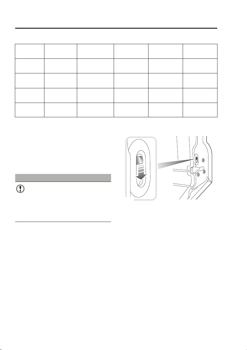
CHILD SAFETY LOCKS
E85681
Child safety locks are fitted to the rear doors to
allow you to prevent accidental opening of the
doors when the vehicle is in motion.
If children are to be carried in the rear seat
positions, it is recommended that the rear door
interior handles are disabled.
Note: For convenience, the rear door interior
handles should be re-enabled when carrying
adult passengers in the rear seat positions.
To change the child lock settings:-
1. Open the door to access the child safety
lock.
2. Move the locking lever up to enable, or
down to disable the interior door handle,
as required.
50
Page 21
Climate control
Climate control
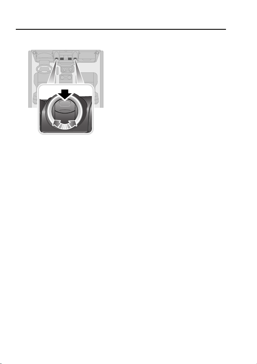
AIR VENTS
E85224
Press the upper portion of the vent to open.
Adjust the direction and volume of air flow to
suit your requirements.
70
Page 22
Climate control
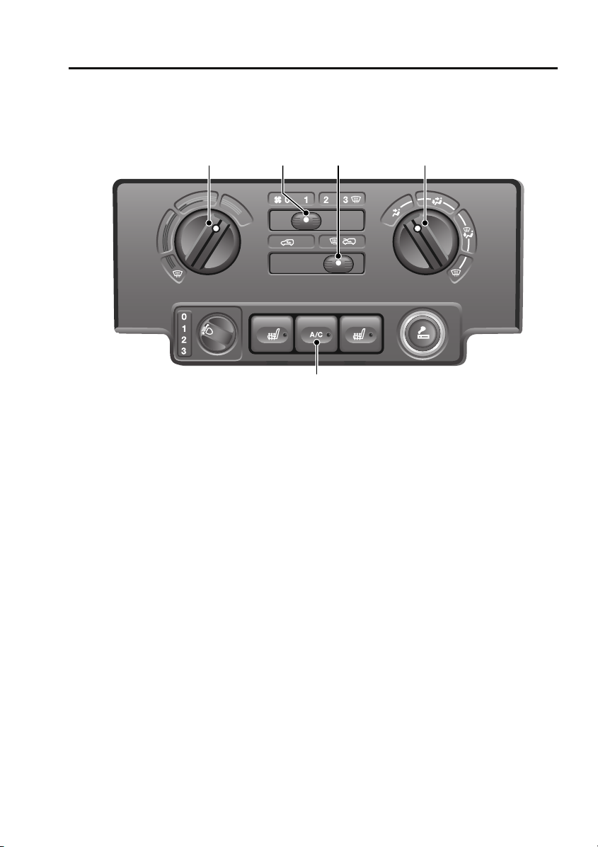
MANUAL CLIMATE CONTROL
Controls
1 42 3
E85225
1. Temperature control, rotate
counterclockwise or clockwise to increase
or decrease temperature accordingly.
2. Blower speed, move the lever towards the
right or left to increase or decrease blower
speed.
3. Recirculation control. Move the lever to the
left or right for recirculated or fresh air.
4. Air distribution. With the blower operating,
rotate to direct air flow as required.
5. Air conditioning control. Press to switch
on and off (switch indicator illuminates
when switched on).
Note: The blower will be switched on
automatically if air conditioning is selected
when the blower is set to 0.
5
Recirculation (3)
When selected, the air is recirculated inside the
vehicle. This helps to maintain a high or low
temperature, and is useful for preventing
fumes from entering the vehicle.
Note: Prolonged use at low temperatures may
cause the windows to mist.
Air distribution (4)
Rotate the control to set the air distribution to
the required points (face, face and feet, feet and
windscreen, windscreen only).
• For maximum heating, set the control to
feet and windscreen.
• For maximum ventilation, set the control to
face only.
• For maximum demisting/defrosting, set
the control to windscreen only.
71
Page 23
Climate control
Air conditioning (5)
Air conditioning provides additional cooling to
the vehicle interior and also reduces the
moisture content of the air.
• In very humid conditions, slight screen
misting may be experienced when air
conditioning is turned on. This will clear in
a few seconds.
• If the interior temperature is higher than
the temperature outside the vehicle, it may
take a short time for the air conditioning to
be effective. It is best, in these
circumstances, to fully ventilate the vehicle
using the blower control, window and
sunroof, prior to switching on the air
conditioning.
• It is recommended that the air conditioning
is operated for a short while every week, to
keep the system in peak condition.
Note: Air conditioning only operates with the
engine running.
Note: The air conditioning system takes power
from the engine and consequently increases
fuel consumption.
Defrost/demist
For maximum defrosting or demisting of the
windows, use the following settings:
• Set the air distribution control to
windscreen only.
• Set the temperature control to maximum.
• Set the blower speed to 3.
• Set the air recirculation control to fresh air
for demisting and defrosting.
• Activate air conditioning.
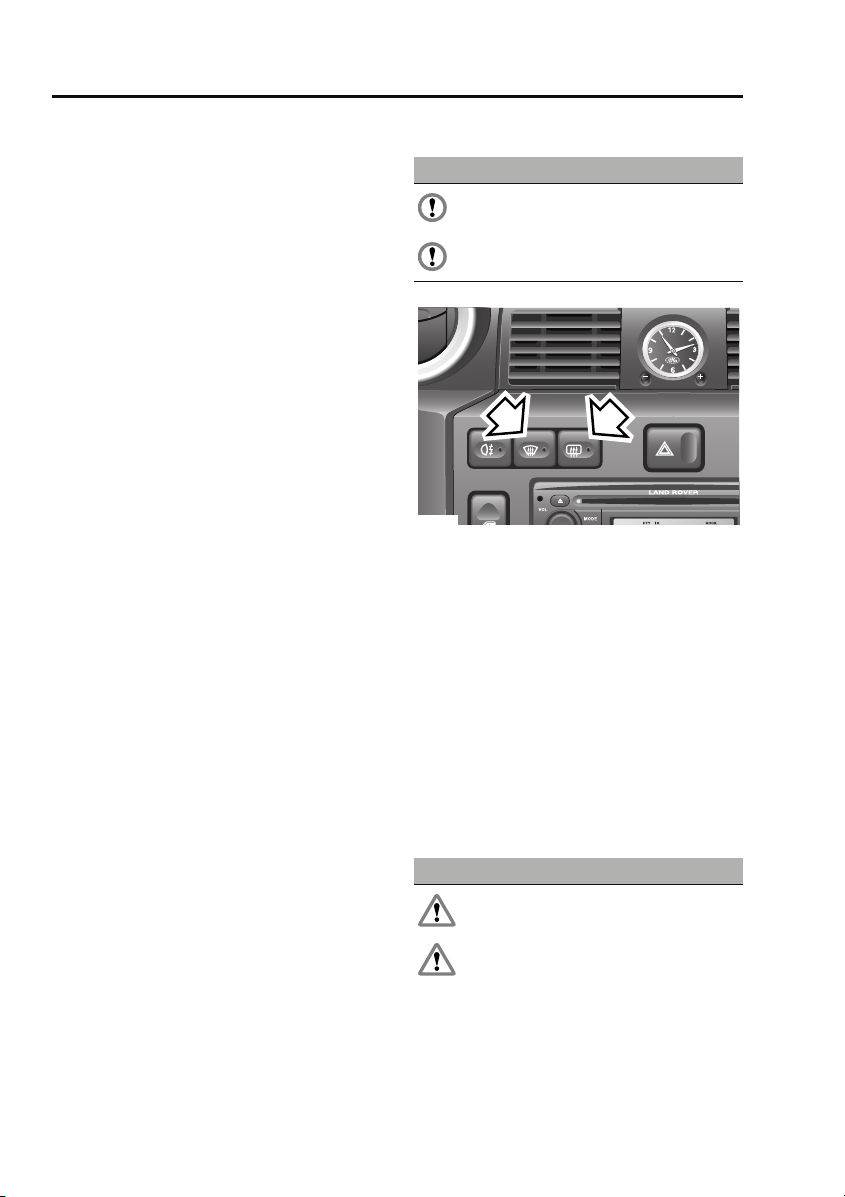
Heated screens
CAUTIONS
Do not stick labels over the heating
elements on the rear screen.
Do not scrape or use abrasive materials
to clean the inside of the rear screen.
1
E85226
1. Heated windscreen
2. Heated rear screen
Press the appropriate switch to operate (switch
indicator illuminates), press a second time to
switch off (indicator extinguishes). The heating
elements will switch off automatically after
approximately eight minutes.
Note: The heated windscreen only operates
with the engine running.
2
SUNROOF
Opening and closing
WARNINGS
Ensure the sunroof is not obstructed
when opening or closing.
Do not allow passengers to extend any
part of their bodies through the sunroof
aperture while the vehicle is moving. Injury
from flying debris, branches of trees, etc.
could occur.
72
Page 24
Climate control
WARNINGS
Always close the sunroof when the
vehicle is left unattended.
E85879
• Turn the handwheel counterclockwise until
the sunroof is open to the required degree.
• Turn the handwheel clockwise until
resistance is felt.
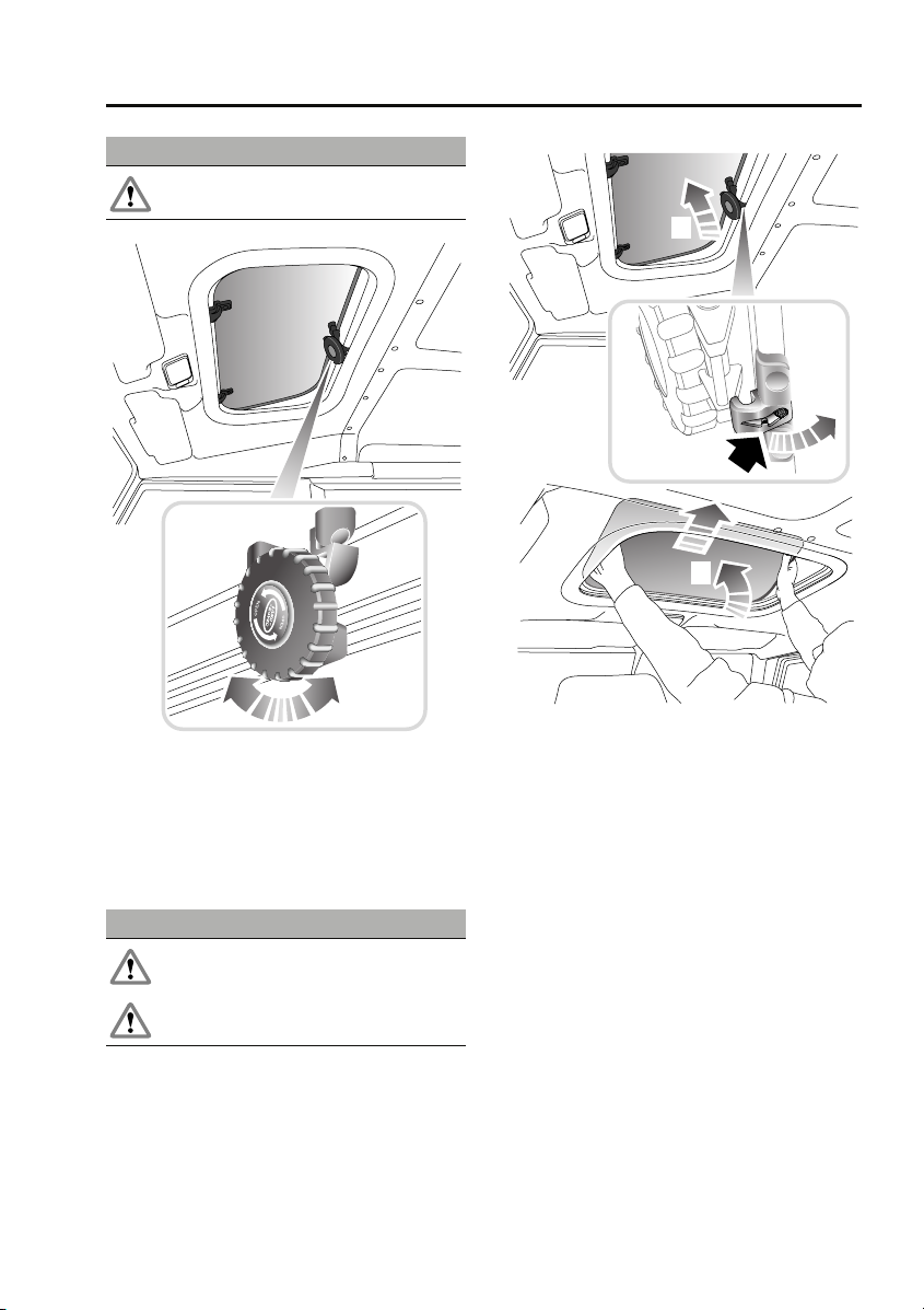
Removing the sunroof
WARNINGS
Do not remove the sunroof when the
vehicle is moving.
Do not store the removed sunroof loose
in the vehicle.
1
2
3
E85880
1. Fully open the sunroof.
2. Push the release catch rearwards (as
arrowed) and disengage the handwheel
mechanism.
3. Using both hands, tilt the sunroof
upwards, then lift rearwards to disengage
the two locating pins.
Rotate the sunroof so that it fits through the
aperture and lower it into the vehicle.
Note: Refit the sunroof by reversing the above
procedure.
73
Page 25

Compact disc player
Compact disc player
LOADING COMPACT DISCS
CAUTIONS
Do not force the disc into the slot.
Only use clean, undamaged discs. Do not
use discs with paper labels, Dual Discs,
DVDPlus discs or discs that are not circular or
are warped. The CD player may load and play
this type of disc; however, it is likely that the
disc will not eject and will block the CD
mechanism. Such damage to a CD player will
not be covered under warranty.
Note: Some music CD manufacturers are
using data encryption to copy-protect their
recordings and prevent the production of
counterfeit copies. These CDs differ from the
internationally agreed CD audio standard,
RedBook, a standard that serves as the
operating basis for all CD players and
changers. Copy-protected CDs may fail to play
in your CD changer or may be played subject to
various limitations, e.g. sound quality may be
impaired. If you do experience a problem, try
the CD in other players before contacting the
CD vendor.
Low quality audio playback
Original recordings employ industry standard
software to ensure high quality reproduction.
Home recordings and pirated copies of original
recordings are unlikely to be of the same
standard; therefore quality of audio playback is
likely to be adversely affected.
Original recordings display the ‘Compact Disc
Digital Audio’ logo. However, pirated copies
may also bear this logo. To ensure your
enjoyment of high quality sound reproduction,
always purchase original recordings.
Loading a CD
To insert a disc into the player, make sure that
the label side of the disc is facing upwards
when you present the disc to the slot. Ease the
disc into the slot a short distance, until the
mechanism takes over and draws the disc in
fully.
Error messages
When there is a problem with the CD player the
head unit may display one of four error codes:
• Error 00 - CD player cannot load the CD.
Possible causes:
- A damaged CD was inserted.
- A CD that does not conform to the
Redbook CD standard was inserted e.g.
wrong shape or size.
- A foreign object was inserted and has
damaged the CD mechanism.
• Error 01 - CD player mechanism fault.
Possible causes:
- The CD player is damaged and can no
longer function.
• Error 02 - CD player reading fault. The CD
player cannot read data from the CD.
Possible causes:
- Dirty or scratched CD.
- An incorrect format CD was inserted e.g.
If the CD player is not equipped to play
CDR MP3/WMA discs.
- CDR with paper label.
- Incorrectly compiled CD e.g. Corrupted
data, unfinished CD writing session,
incorrect "ripping" process used to make
the CD.
- A CDR that does not conform to the
Orangebook standard was inserted e.g. a
non-compliant CDR that does not bear a
recognised brand.
- The CD player has become too hot e.g.
due to excessive heater usage.
162
Page 26

Compact disc player
• Error 03 - CD player electronic fault. The
CD player cannot read data from the CD.
- The CD player is damaged and can no
longer read the CD.
Redbook is the specification that
controls the CD standard - look for
the "Compact Disc Digital Audio"
logo. The head unit is designed to play
Redbook CDs and may not play CDs that do not
conform to this standard e.g. a disc that has
multiple content including video that may be
played on a Personal Computer PC or
Macintosh machine.
Orangebook is the specification
that controls the CDR standard -
look for the "Compact Disc
Recordable" logo. The MP3 and WMA
compatible head unit is designed to play
Orangebook CDRs and may not play
unbranded CDRs or CDRs with corrupted or
incorrect formats and data types present (see
Error 02 causes).
EJECTING COMPACT DISCS
To eject the disc, press and release the eject
button. A confirmation message is displayed.
After a short pause, the compact disc will
emerge and you can then remove it.
Note: If the disc is not removed from the slot
within ten seconds, it will be drawn back into
the player automatically.
Note: If you eject a CD during playback, the
audio unit will switch to tuner mode
automatically.
CD is hot when ejected
CDs will become hot when played for extended
periods - this is normal. This condition may
occur when the vehicle is excessively heated by
the vehicles heating system e.g. when the user
selects a maximum heating setting and drives
with the windows open to cool the cabin
temperature; heat will build up in the centre
console and the CD player which cannot be
dissipated adequately to ensure CD playback.
This condition may cause CD playback to falter
or stop altogether. The user should reduce
heating and allow the CD player to cool down.
163
Page 27
Compact disc player
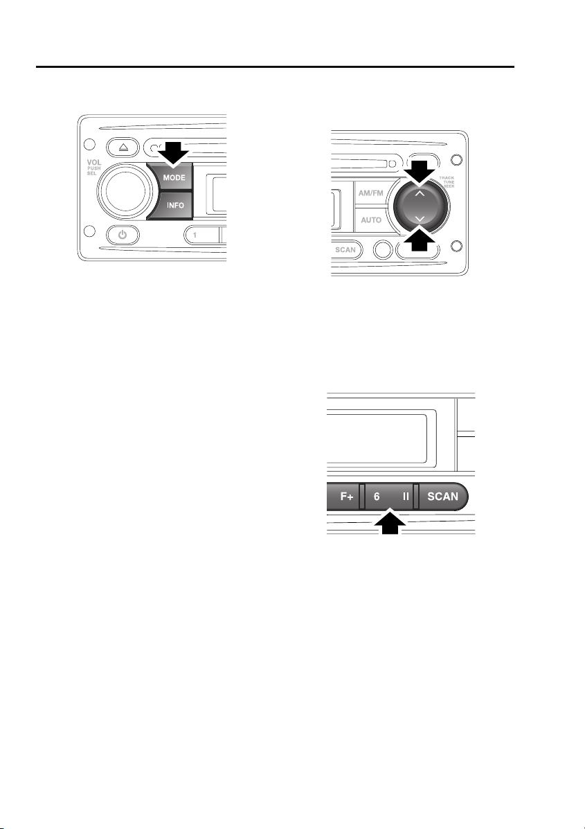
COMPACT DISC PLAYBACK
E85379
If you insert a compact disc into the compact
disc slot, play will start automatically.
To start playing a compact disc that is already
inserted, press and release the MODE button
repeatedly until CD mode is selected. Playback
will begin at one of two places:
• If the disc has not been removed since its
last use, playback will begin from the point
at which it was stopped previously.
• If the disc is being inserted for the first
time, playback will begin at the first track.
Note: Driving on very uneven or bumpy ground
may cause the sound to skip during playback.
Note: If the vehicle is very cold or damp when
the CD is first loaded, moisture in the audio unit
may interfere with playback.
TRACK SELECTION
CD track selection
E84859
To skip to the next track or return to the start of
the current track during playback, press and
release either the up or down arrow on the
search button.
COMPACT DISC PAUSE
E84863
To pause or stop compact disc playback,
briefly press the pause button. If you press and
release the MODE button to move to the Tuner
or Auxiliary modes, CD playback will be paused
until you return to CD mode.
164
Page 28
Compact disc player
FAST FORWARD/REVERSE
Search button
E84859
To move forwards or backwards through the
current CD track, press and hold down either
the up or down arrow on the search button. To
continue playback, release the search button.
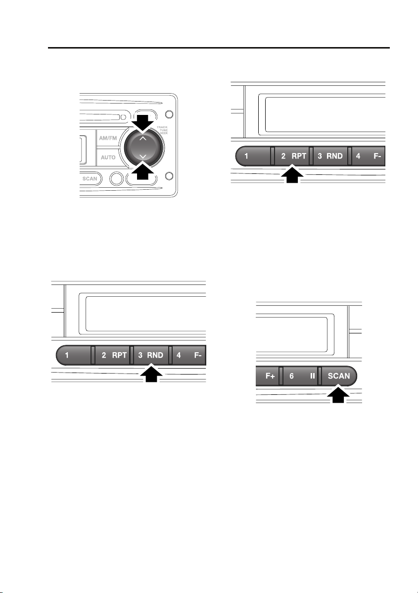
RANDOM TRACK SELECTION
REPEAT COMPACT DISC TRACKS
E85377
Repeat allows the current track to play
repeatedly until it is stopped or cancelled.
To repeat the current track, press and release
the 2 RPT button. Press the button again to
turn the Repeat function off and continue
playing any remaining tracks.
COMPACT DISC TRACK SCANNING
E85376
The Random function alters the playback
sequence for the loaded compact disc. If the
Random function is switched on, the track
playback sequence is selected randomly.
To activate the random selection of tracks
during playback, press the 3 RND button. To
turn random track selection off, press the 3
RND button again.
E85378
Compact disc track scan allows you to sample
the music on a compact disc. This feature plays
the first ten seconds of each track in numerical
order. Play will then begin at the start of track
one.
To activate CD track scanning, press and
release the SCAN button.
165
Page 29

Compact disc player
Note: While in CD scan mode, pressing the
previous track button will resume normal play
of the current track. Pressing the next track
button will move to the next track and resume
normal play.
MP3 FILE PLAYBACK
When a data disc (containing MP3-encrypted
music data) is inserted into the compact disc
slot, MP3 will appear at the top left of the
display. If your audio unit is not able to play
MP3 discs, then the disc will not be
recognised. If your disc contains
WMA-encrypted files, then the display shows
WMA.
Note: To make sure that the best sound quality
is achieved, you need to read and adhere to the
instructions or information provided with the
recording software.
Note: Some CD-R and CD-RW discs are more
susceptible to damage by heat and
condensation than standard audio CDs. Do not
leave data discs in the audio unit for long
periods of time.
Note: Some discs recorded in CD-R or CD-RW
mode may not be usable.
166
Page 30
Compact disc player
Searching an MP3 data disc
When you insert the disc, the audio unit will
play all the tracks in the order they appear. The
tracks are numbered as they are ordered in a
folder. Press the DISP button repeatedly to
scroll through the file information shown on
the display.
If you want to move to another folder on the
disc, press the 4 F- or 5 F+ buttons to move to
the next or previous folder.
To select from a list of MP3 files, do the
following:
1. Press and release the AUTO button. The
information display will show MP3 T*.
2. Rotate the volume control to scroll through
the track list.
3. Press and release the volume control to
select and play your chosen track.
To search for specific MP3 track titles, do the
following:
1. Press and release the AUTO button twice.
The information display will show _ _ _ _
_.
2. Rotate the volume control to scroll through
the letters A to Z to find the first letter of the
track title you are searching for.
3. Press and release the volume control once
to select the first letter of the track title.
4. Repeat steps 2 and 3 to select the second
and any subsequent letters of the track
title.
5. When you have selected as many letters as
required to find the track, press the up or
down arrows on the search button to
locate and select it.
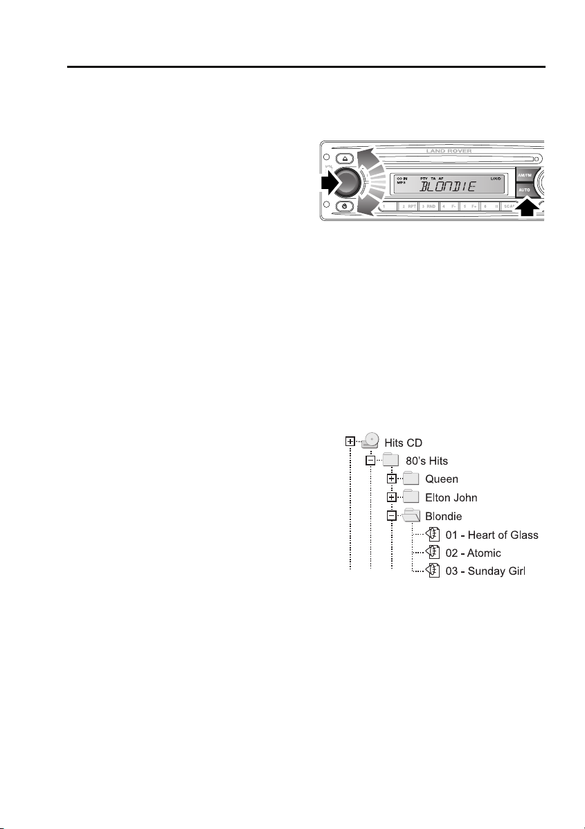
To browse a folder structure on an MP3 disc,
do the following:
E88679
1. Press and release the AUTO button three
times.
2. Rotate the volume control to scroll through
the list of folders at that level.
3. Press and release the volume control to
select a folder and move down to that
folder level. Rotate the volume control
again to scroll through the files and/or
folders in that folder. A typical folder
structure is illustrated below:
E88700
4. Press and release the volume control to
play a selected file.
Note: Select the .. entry in a list to move up a
folder level.
167
Page 31

Convenience features
SUN VISORS
E85227
Convenience features
CIGAR LIGHTER
CLOCK
E85228
Press the + or - buttons to advance or put back
the time.
Note: The clock will need to be reset if the
battery is disconnected.
E85229
With the starter switch turned on, press in the
centre of the cigar lighter. When the cigar
lighter element has reached the correct
temperature it will partially eject and can be
withdrawn for use.
After use push the lighter back into the first
position.
74
Page 32

Convenience features
ASHTRAY
E85230
WARNING
Do not use the ashtrays for disposing of
waste paper, or other combustible
items. The resulting fire may cause death or
serious injury.
To empty, pull out the complete ashtray.
CUP HOLDERS
E85231
WARNINGS
The cup holders should only be used
for soft containers. Containers which
are hard (cans, metal, ceramic, hard plastic
etc.) can cause serious injury if the vehicle is
involved in an accident, sudden manoeuvre or
braking.
Do not carry open drinks containers.
Hot liquids can cause serious injury
when spilled and may damage the vehicle.
Do not drink, or use the drinks holders
when driving. Doing so would break
concentration, which may result in loss of
control.
75
Page 33

Convenience features
STORAGE COMPARTMENTS
Cubby box
E89003
Open the lid to access the storage
compartment.
STEPS
Rear step
E88550
Side steps
E88549
The steps are designed to be folded down for
use and folded up when not required.
76
Page 34

Detachable roof
Detachable roof
FITTING THE ROOF
Note: It is recommended that roof fitting is
performed by two people.
E86798
Lay the canopy on the open tailgate.
E86800
From the rear, lift the canopy over the frame,
ensuring that the front window is against the
window of the cab.
E86799
Unfold the canopy into the load area.
E86801
Prior to fastening the canopy to the vehicle, it
should resemble the illustration above.
77
Page 35

Detachable roof
E86804
E86802
Roll up the canopy rear screen to improve
access to the rear of the vehicle and secure
with the tether straps.
E86803
Remove the spare wheel. See CHANGING A
ROAD WHEEL (page 128).Slot the metal
retaining strip into the canvas pocket below the
cab window. Align the holes in the strip with
those in the body and insert the four
turnbuckles. Twist the turnbuckles clockwise
to secure.
Note: Refit the spare wheel.
Pull and attach both rubber hoops to the hooks
above the rear lamps as shown.
E86805
Starting at the front of the canopy, loop the tie
rope over each of the hooks along the side of
the vehicle. Ensure that each loop is tightened
before the next loop is made.
78
Page 36

Detachable roof
E86806
Fasten the tie rope to the hook above the rear
lamps.
E86808
Close the tailgate, then pull the tie rope through
the last loop and then through the gripper unit
as shown. Tie off any excess rope length.
E86807
Unroll the canopy rear screen and secure to the
rear panels by threading each rope loop
through the loop above and pull downwards as
shown.
E86809
The finished canopy should look as shown.
Note: The process for removing the roof is a
reversal of the fitting process.
79
Page 37

Driving hints
Driving hints
RUNNING-IN
The engine, gearbox, tyres and brakes, need
time to bed-in. During the first 800 km (500
miles), it is essential that the vehicle is driven
with consideration for the running-in process.
During the running in period, the following
advice should be followed.
• Limit the engine speed to a maximum of
3000 rpm and the road speed to a
maximum of 80 km/h (50 mph).
• Do not use full accelerator pedal travel and
use the gears to avoid over-revving or
labouring the engine.
• Avoid rapid acceleration or heavy braking
wherever possible.
• Ensure that servicing is carried out on time
and follow any advice regarding use in
arduous conditions.
Note: The advice given for running in will aid
fuel economy and should be adopted as
general driving practice, even after the running
in period.
ECONOMICAL DRIVING
There are two main factors which influence fuel
economy, the way the vehicle is driven, and
maintenance.
Driving tips for economy
• Avoid unnecessary journeys, especially
short stop-start trips.
• Accelerate smoothly and gently from a
stand still.
• Use the gears to avoid labouring or
over-revving the engine.
• Allow time to brake gently and smoothly.
• Be aware of traffic and road conditions
ahead and take action in time to avoid hard
braking or acceleration.
• When stationary apply the parking brake,
and select neutral.
• Turn off the air conditioning when not
needed.
Maintenance and fuel economy
Regular servicing by a Land Rover
Dealer/Authorised Repairer, along with regular
checks by the driver, are essential for vehicle
longevity and fuel economy.
The condition of the engine (oils, filters,
settings etc.), tyre pressures and wheel
alignment, will all have a bearing on fuel
economy. For this reason, it is essential that
the vehicle is checked regularly by the driver
and serviced by an approved Land Rover
Dealer/Authorised Repairer at the correct
intervals.
Note: If you are in any doubt about the
maintenance requirements, intervals or checks
required, contact your Land Rover
Dealer/Authorised Repairer for advice.
88
Page 38

Emergency equipment
Emergency equipment
HAZARD WARNING FLASHERS
E85198
If the vehicle is stationary in an unsafe location,
or may cause a hazard to other road users,
switch on the hazard warning flashers. Press
the switch to turn the hazard warning lamps
on.
Note: Hazard warning lamps can be used when
the starter switch is turned on or off.
141
Page 39

Filling station information
Filling station information
FILLING STATION INFORMATION
Fuel filler cap
E83705
E94107
To unlock and remove the filler cap:
1. Hold the filler cap steady, insert the key
2. Remove the key.
3. Unscrew the filler cap, gradually at first,
4. Remove the filler cap.
To replace and lock the filler cap:
1. Replace the filler cap into the fuel filler.
2. Turn and tighten the filler cap clockwise,
3. Hold the filler cap steady, insert the key
4. Remove the key.
5. The filler cap is now locked, but can rotate.
A small arrow on the fuel gauge
indicates which side of the vehicle
the fuel filler cap is located.
and turn it a half-turn anti-clockwise.
allowing the fuel tank to vent.
until it clicks three times.
and turn it a half-turn clockwise.
Refuelling
E85240
Never continue filling once the filling station
pump has automatically cut-off.
After refuelling, tighten the filler cap until it
clicks three times.
Fuel tank capacity
Model Litres Gallons
90 57 12.54
110 73 16.06
Tyre pressures
Details of the tyre pressures for each derivative
and wheel and tyre combination can be found
later in this book. See TECHNICAL
SPECIFICATIONS (page 136).
Fuel specification
The correct fuel specification for your vehicle is
shown next to the fuel filler cap. See
TECHNICAL SPECIFICATIONS (page 114).
Incorrect fuelling
CAUTION
If the fuel tank is accidentally filled with
the wrong type of fuel, it is essential that
the engine is not started and that you seek
qualified assistance.
24
Page 40

Filling station information
Engine oil specification
Model Specification
Diesel engine Use only 5W-30 oil
meeting Land Rover
specification
WSS-M2C913-B.
Engine coolant specification
Top-up to the upper level indicator mark. Use
only a 50% mix of water and Texaco XLC
antifreeze. See ENGINE COOLANT CHECK
(page 108).
25
Page 41

Fuel and refuelling
Fuel and refuelling
SAFETY PRECAUTIONS FUEL QUALITY
WARNINGS
Petroleum gasses are highly
flammable, have a low flash point, and
are explosive, especially in confined spaces.
Avoid exposing the gasses to any potential
sources of ignition as the resulting fire and
explosion may cause serious injuries and/or
death.
Only use containers specifically
designed for carrying fuel, and always
remove them from the vehicle to fill them.
Failure to do so may result in spillage, and
cause a fire.
Switch off the engine when refuelling,
as it is both a source of extreme
temperatures, and electrical sparks. The
resulting fire and explosion may cause serious
injury and death.
Switch off any personal electronic
devices such as mobile phones, or
music players. They have the potential to
cause electrical sparks. The resulting fire and
explosion may cause serious injury and death.
Do not smoke, use a naked flame, or
cause sparks. The resulting fire and
explosion may cause serious injury and death.
Do not overfill the fuel tank. Overfilling
may cause spillage when the vehicle is
driven. Spillage may also occur if the fuel
expands in high ambient temperatures.
Note: Land Rover vehicles are capable of
running with up to a 5% blend of bio-diesel, in
accordance with European Standard EN590.
Sulphur content
The Sulphur content of diesel used in Land
Rover vehicles should not exceed 0.3%.
In some countries, diesel will contain higher
levers of Sulphur, which will require reduced
service intervals to reduce the effects on
engine components. If in doubt, contact a local
Land Rover Dealer/Authorised Repairer for
advice.
RUNNING OUT OF FUEL
Avoid running out of fuel. Doing so can
cause damage to the vehicle's engine,
fuel and emission control systems.
Note: If the vehicle does run out of fuel, a
minimum of 4 litres (0.8 gallons) will be
required to restart the engine. The vehicle will
need to be driven 1.6-5 km (1-3 miles) in order
to reset the engine management and
monitoring systems.
Note: If the vehicle does run out of fuel,
seeking qualified assistance is advisable.
CAUTION
89
Page 42

Fuel and refuelling
REFUELLING
Fuel filler cap
WARNING
Do not fully remove the fuel filler cap
until any captive tank pressure has been
released (wait until the hissing stops).
The fuel filler is located in the right-hand rear
body side.
E94107
To unlock and remove the filler cap:
1. Hold the filler cap steady, insert the key
and turn it a half-turn anti-clockwise.
2. Remove the key.
3. Unscrew the filler cap, gradually at first,
allowing the fuel tank to vent.
4. Remove the filler cap.
E85239
To replace and lock the filler cap:
1. Replace the filler cap into the fuel filler.
2. Turn and tighten the filler cap clockwise,
until it clicks three times.
3. Hold the filler cap steady, insert the key
and turn it a half-turn clockwise.
4. Remove the key.
5. The filler cap is now locked, but can rotate.
Fuel filling
WARNINGS
When refuelling, ensure that all
windows, doors and sunroof are fully
closed, particularly if young children or
animals are in the vehicle. Fuel vapour
contains harmful chemical compounds, some
of which may cause cancer.
Do not attempt to fill the tank to its
maximum capacity. If the vehicle is to
be parked on a slope, in direct sunlight, or high
ambient temperature, expansion of the fuel
could cause spillage.
CAUTIONS
Ensure that you check the fuel pump
information carefully, to ensure that you
are putting the correct fuel into the vehicle.
Filling a vehicle with the incorrect fuel can
cause serious engine and fuel system damage.
90
Page 43

Fuel and refuelling
CAUTIONS
If the vehicle is filled with incorrect fuel,
it is essential that you seek qualified
assistance before you start the engine.
Running the engine can cause serious engine
and fuel system damage.
Note: Filling station pumps used for diesel
commercial vehicles deliver fuel at a higher
rate than normal. The higher fill rate can cause
premature cut-off and may cause fuel spillage.
Therefore, it is recommended that only
standard light vehicle pumps are used. Filling station pumps are equipped with
TECHNICAL SPECIFICATIONS
Fuel consumption
Variant Urban Extra-urban Combined CO2 emissions
l/100 km (mpg) l/100 km (mpg) l/100 km (mpg) g/km
90 Station Wagon 12.5 (22.6) 8.6 (32.9) 10.0 (28.3) 228
90 Commercial 13.3 (21.2) 8.6 (32.9) 10.3 (27.4) 229
110 Station Wagon 13.5 (20.9) 9.5 (29.7) 11.0 (25.7) 252
110 Commercial 13.6 (20.8) 9.7 (29.1) 11.1 (25.5) 295
130 Commercial 13.6 (20.8) 9.7 (29.1) 11.1 (25.5) 295
E85240
automatic cut-off sensing, to avoid fuel
spillage. Do not attempt to fill the tank beyond
this cut-off point or spillage may occur due to
fuel expansion.
Fuel specification
Diesel
EN 590
91
Page 44

Fuses
Fuses
CHANGING A FUSE
CAUTIONS
Fit Land Rover approved replacement
fuses of the same rating and type, or
fuses of matching specification. Using an
incorrect fuse may result in damage to the
vehicle's electrical system, and can result in a
fire.
If the replacement fuse blows after
installation the system should be
checked by your Land Rover
Dealer/Authorised Repairer.
Note: Land Rover recommend that owners do
not remove or replace relays. It is
recommended that you seek qualified
assistance in the event of a relay failure.
Always switch off the ignition, and the affected
electrical circuit before replacing a fuse.
FUSE BOX LOCATIONS
There are two fuse boxes in the vehicle, the
main fuse box and the secondary fuse box. A
label in each fuse box cover shows the circuits
protected, the fuse values and their locations.
See FUSE SPECIFICATION CHART (page 138).
Main fuse box
E85095
The main fuse box is fitted below and to one
side of the steering column; to access the
fuses, remove the cover by turning the fixing
screws fully counterclockwise.
Secondary fuse box
E85096
The secondary fuse box is located under the
right front seat. See MANUAL SEATS
(page 39).
137
Page 45

To access the fuses, press the catch on the
fuse box (arrowed in illustration) and lift the
cover. See FUSE SPECIFICATION CHART
(page 138).
FUSE SPECIFICATION CHART
Fuse positions and specifications
Main fuse box
Fuses
F47
F46
F45
F44
F43
F42
F41
F40
F39
F38
E85097
F37
F36
F35
F34
F33
F32
F31
F30
F29
F28
F27
F26
F25
F24
F23
F22
F21
F20
F19
F18
F17
F16
F15
F14
F13
F12
F11
F10
F9
F8
Fuse number Rating (Amps) Fuse colour Circuits protected
F8 10 Red Alarm system
F9 15 Blue Front wipers/wash
F10 10 Red Rear wipers/wash
F11 10 Red Anti-lock brakes
F12 10 Red Speed transducer
F13 10 Red Brake lamps
F14 10 Red Reverse lamps
F15 5 Tan Ignition
F16 - - Not used
F17 - - Not used
F18 10 Red Side lamps (left)
F19 10 Red Side lamps (right)
F20 10 Red Illumination/clock illumination
F21 10 Red Hazard switch
F22 10 Red Headlamp dipped beam (right)
F23 10 Red Headlamp dipped beam (left)
138
Page 46

Fuses
Fuse number Rating (Amps) Fuse colour Circuits protected
F24 10 Red Headlamp main beam (right)
F25 10 Red Headlamp main beam (left)
F26 10 Red Rear fog lamps
F27 10 Red Alarm sounder
F28 20 Yellow Heated rear window
F29 20 Yellow Cooling fan/A/C clutch link
F30 10 Red Audio/clock/diagnostic socket
F31 15 Blue Hazard switch
F32 - - Not used
F33 20 Yellow Seat heater
F34 20 Yellow Electric window (right)
F35 20 Yellow Electric window (left)
F36 30 Green Heated front screen
F37 30 Green Spare fuse
F38 10 Red Engine ECU/PCM
F39 5 Tan Engine ECU/PCM
F40 - - Not used
F41 5 Tan Engine ECU/PCM
F42 10 Red Air conditioning switch
F43 20 Yellow Cigar lighter
F44 5 Tan Audio unit
F45 30 Green Blower motor
F46 - - Not used
F47 - - Not used
139
Page 47

Fuses
Secondary fuse box
F7
F6
F5
F4
F3
F2
F1
E85098
Fuse number Rating (Amps) Fuse colour Circuits protected
F1 30 Green Anti-lock braking
F2 20 Yellow Accessory socket
F3 20 Yellow Headlamp flash/horn
F4 - - Not used
F5 30 Green Main relay
F6 15 Blue Alarm system
F7 20 Yellow Alarm system
CAUTION
You are strongly advised against
removing or replacing the fuses
identified on the underside of the secondary
fuse box lid as: 100A, 60A, 60A, 30A, 60A and
30A. Failure of any of these fuses should be
investigated by a qualified technician only.
140
Page 48

Instruments
Instruments
INSTRUMENT PANEL OVERVIEW
Instrument panel
1 2 3 4
E85173
1. Tachometer.
2. Temperature gauge.
3. Fuel gauge.
4. Speedometer.
5. Odometer and trip recorder.
6. Trip recorder reset button.
Tachometer
Indicates engine speed in revolutions per
minute (RPM) x 1000.
Temperature gauge
CAUTION
Serious engine damage can occur if the
vehicle is driven whilst the engine is
overheating.
If the pointer moves onto the red line, severe
engine damage can occur.
56
If the engine overheats, stop the vehicle and
allow the engine to idle until the temperature
lowers. Do not switch the engine off
immediately, as the cooling system cannot
operate with the engine switched off. If the
temperature does not reduce, or the problem
reoccurs, seek qualified assistance.
Note: If engine temperature rises to the point
where overheating may occur, there may be a
noticeable reduction in engine power, and the
air conditioning may cease operation. This is a
normal operating strategy to reduce load on
the engine and assist with cooling.
65
Page 49

Instruments
Fuel gauge
CAUTION
Never allow the vehicle to run out of fuel.
The resulting mis-fire may cause serious
damage to the catalytic convertor.
Once the fuel level has dropped to the point
where the range is approximately 80 km (50
miles) the low fuel warning indicator will
illuminate.
As a reminder for the location of the fuel filler,
there is an arrow next to the fuel pump symbol
which points to the relevant side of the vehicle.
Speedometer
Indicates road speed.
Odometer
Indicates the total distance which the vehicle
has travelled.
Trip recorder
Indicates the distance travelled since the last
reset, and can be used to measure the distance
of individual journeys.
Trip recorder reset button
Resets the distance shown on the trip recorder
to zero.
Note: Once the trip recorder has been reset to
zero, the previously recorded distance will be
lost.
66
Page 50

Instruments
WARNING LAMPS AND INDICATORS
E85154
The location and specification of warning
lamps and indicators may vary, according to
model and market requirements.
Battery charging - Red
Illuminates as a bulb check when
the starter switch is turned to
position II and extinguishes once
the engine is running. If it remains on, or
illuminates when driving, a fault is indicated.
Seek qualified assistance urgently.
Low oil pressure - Red
Illuminates as a bulb check when
the starter switch is turned to
position II and extinguishes when
the engine is started. If the indicator remains
on, flashes on and off, or illuminates when
driving, stop the vehicle as soon as safety
permits and switch off the engine
immediately. Seek qualified assistance before
driving.
Always check the oil level if this indicator
illuminates.
Glow plug - Amber
Illuminates when the starter switch
is turned to position II. Wait until the
indicator has extinguished before
starting the engine.
Seat belt - Red
Illuminates if the driver's seat belt
remains unfastened when the
vehicle is in motion and is
accompanied by an audible warning. The
warning indicator will remain illuminated until
the seat belt is fastened correctly.
Check engine - Amber
Illuminates as a bulb and system
check when the starter switch is
turned on and extinguishes as soon
as the engine starts. Illumination at any other
time indicates an engine fault. If the indicator
illuminates while driving, avoid high speeds
and seek qualified assistance urgently.
67
Page 51

Instruments
Direction indicators - Green
The left or right warning indicator
flashes in conjunction with the
relevant direction indicator. If the
warning indicator fails to flash, or flashes very
rapidly, this may indicate that one of the
direction indicator bulbs has failed.
Both warning indicators will flash in
conjunction with the direction indicators, when
the hazard warning lamps are selected.
Side lamps on - Green
Illuminates whenever the side
lamps are on.
Headlamp main beam - Blue
Illuminates when the headlamps are
switched to main beam.
Hazard warning lamps
Flashes in conjunction with the
direction indicator warning
indicators when the hazard warning
lamps are operating.
Brake systems - Red/Amber
This indicator shares its position
and symbol with four brake system
warnings and illuminates briefly as a
bulb check when the starter switch is turned to
position II (the indicator will illuminate red and
amber during bulb check).
Parking brake - Red
Illuminates when the parking brake is applied
with the starter switch in position II. The
indicator should extinguish when the parking
brake is fully released. If the indicator
illuminates when driving (and the parking
brake is not applied), a fault is indicated. Seek
qualified assistance before continuing.
Brake fluid level - Red
Illuminates when the brake fluid level is low. If
the indicator illuminates when driving (and the
parking brake is not applied), stop the vehicle
gently, as soon as safety permits. Check and
top-up the brake fluid, if necessary. If the lamp
remains illuminated, seek qualified assistance
before continuing. Have the problem checked
by your Land Rover Dealer/Authorised
Repairer.
Electronic Brake Force Distribution (EBD) Red
Illuminates when a fault with the EBD system is
detected. If the indicator illuminates when
driving (and the parking brake is not applied),
stop the vehicle gently, as soon as safety
permits. Check and top-up the brake fluid, if
necessary. If the lamp remains illuminated,
seek qualified assistance before continuing.
Have the problem checked by your Land Rover
Dealer/Authorised Repairer.
Anti-lock braking system - Amber
Illuminates as a bulb check when
the starter switch is turned to
position II If the indicator remains
on or illuminates when driving, a fault with the
ABS system is indicated. Drive with extra care,
avoiding heavy brake application and seek
qualified assistance urgently.
Trailer direction indicators - Green
Flashes in conjunction with the
direction indicator warning
indicators, when a trailer is attached
to the vehicle. If it does not flash, this indicates
that a trailer bulb is defective.
68
Page 52

Instruments
Traction control - Amber
The indicator illuminates for a
minimum of two seconds whenever
traction control is operating. If the
indicator illuminates continuously, a fault with
the system is indicated. Seek qualified
assistance urgently.
Heated rear screen - Amber
Illuminates when the rear screen
heater is operating.
Differential lock - Amber
Illuminates whenever the differential
is locked. If the indicator remains
illuminated after the differential lock
is disengaged, transmission wind-up may be
present. Reversing the vehicle a short distance
and then driving forward will usually unwind
the transmission. If the indicator remains on,
seek qualified assistance as soon as possible.
Rear fog lamp - Amber
Illuminates whenever the rear fog
lamps are on.
Over-speed warning - Amber (Gulf states
only)
If the road speed exceeds 120 km/h
(75 mph), the indicator flashes for
five seconds and then, if the road
speed reaches 124 km/h (77 mph), illuminates
continuously. The indicator will remain
illuminated until the road speed reduces to 117
km/h (73 mph). Illumination of the warning
indicator is accompanied by an audible
warning.
Low fuel - Amber
E85159
hen the fuel remaining in the tank drops to a
minimum of 9 litres (2 gallons). If the indicator
illuminates, refuel at the first opportunity.
Il
l
u
m
i
n
a
t
e
s
w
69
Page 53

Introduction
Introduction
SYMBOLS GLOSSARY
Warnings
WARNING
Safety warnings are included in this
handbook. These indicate either a
procedure which must be followed precisely,
or information that should be considered with
great care in order to avoid the possibility of
personal injury.
Cautions
CAUTION
Cautions are included in this handbook.
These indicate either a procedure which
must be followed precisely, or information that
should be considered with great care in order
to avoid the possibility of damage to your
vehicle.
Symbols
This recycling symbol identifies
those items that must be disposed
of safely in order to prevent
unnecessary damage to the environment.
This symbol identifies those
features that can be adjusted,
disabled or enabled by a Land Rover
Dealer/Authorised Repairer.
LABEL LOCATIONS
Warning labels attached to your
vehicle bearing this symbol mean:
E83651
Do not touch or adjust components
until you have read the relevant
instructions in the handbook.
Labels showing this symbol
indicate that the ignition system
E83652
utilises very high voltages. Do not
touch any ignition components
while the starter switch is turned on.
Warning labels
Labels are attached to your vehicle at several
positions. These are applied to draw your
attention to important subjects, e.g. tyre
pressures, tow bar use, roll-over risk, engine
compartment hazards, etc.
26
Page 54

Introduction
5
4
E85734
1. Fan cowl - Fan warning label, air
conditioning label and Genuine Parts
label
2. Top face of battery - Battery warning
symbols
3. Facia - Transmission label
4. On right-hand rear wheel arch - Vehicle
jacking label. Australia only - Tyre
pressures label
5. Adjacent to the fuel filler cap - Fuel
specification label
It is important that you are familiar with these
subjects to ensure that your vehicle and its
features are used safely. Using the index at the
back of this handbook, refer to the relevant
topic for more information.
1
2
3
HEALTH AND SAFETY
WARNINGS
Your vehicle has a higher ground
clearance and hence, a higher centre of
gravity than ordinary passenger cars, to
enable the vehicle to perform in a wide variety
of off-road applications. An advantage of the
higher ground clearance is a better view of the
road allowing you to anticipate problems.
The vehicle is not designed for
cornering at the same speed as
conventional passenger cars any more than a
low-slung sports car is designed to perform
satisfactorily under off-road conditions. If at
all possible, avoid sharp turns or abrupt
manoeuvres. As with other vehicles of this
type, failure to operate the vehicle correctly
may result in loss of control or vehicle
roll-over.
The vehicle should not be parked over
long dry grass or other combustible
material, particularly during dry weather. As
the heat generated by the exhaust and
emission control systems may be sufficient to
start a fire.
DATA RECORDING
Service data recording
Service data recorders in your vehicle are
capable of collecting and storing diagnostic
information about your vehicle. This potentially
includes information about the performance or
status of various systems and modules in the
vehicle such as engine, throttle, steering or
brakes.
In order to properly diagnose and service your
vehicle, Land Rover and service and repair
facilities may access vehicle diagnostic
information through a direct connection to
your vehicle.
27
Page 55

Introduction
PARTS AND ACCESSORIES
WARNINGS
The fitting of non-approved parts and
accessories, or the carrying out of
non-approved alterations or conversions, may
be dangerous and could affect the safety of the
vehicle and occupants and also invalidate the
terms and conditions of the vehicle warranty.
Land Rover will not accept any liability
for death, personal injury or damage to
property which may occur as a direct result of
fitment of non-approved accessories or the
carrying out of non-approved conversions to
Land Rover vehicles.
Land Rover strongly advise against
making any modifications to the
suspension or steering system. This could
seriously affect the handling and stability of
the vehicle leading to loss of control or
roll-over.
parts and accessories that have been
developed and tested to the same stringent
standards as the original components will
safeguard the continued reliability, safety and
performance of your vehicle.
To augment the vehicle's already impressive
performance, a comprehensive range of Land
Rover approved spare parts and accessories is
available, enabling the vehicle to fulfil a wide
variety of roles, and enhancing and protecting
the vehicle in the many tasks to which it can be
applied.
Land Rover parts are the only parts built to
original equipment specifications and
approved by Land Rover designers; this means
that every single part and accessory has been
rigorously tested by the same engineering
team that designed and built the vehicle and
can therefore be guaranteed for twelve months
with unlimited mileage.
A full list and description of all accessories is
available from your Land Rover
Dealer/Authorised Repairer.
E88154
The vehicle has been designed, built and tested
to cope with a variety of off-road driving
conditions, some of which can place the
severest possible demands on control systems
and components. As such, fitting replacement
28
Page 56

Introduction
Electrical equipment
WARNING
It is extremely hazardous to fit or
replace parts or accessories, the
installation of which requires the dismantling
of, or addition to, either the electrical or fuel
systems.
Always consult a Land Rover
Dealer/Authorised Repairer before fitting any
accessory.
Fitting inferior quality parts or accessories,
may be dangerous and could invalidate the
vehicle warranty.
It is recommended that you always consult a
Land Rover Dealer/Authorised Repairer for
advice regarding the approval, suitability,
installation and use of any parts or accessories
before fitting.
After-sales service
Travelling abroad
In certain countries, it is a legal requirement to
fit parts made to the vehicle manufacturers'
specification.
Owners should ensure that any parts or
accessories fitted to the vehicle while travelling
abroad, will also conform to the legal
requirements of their own country when they
return home.
E84193
The After Sales Parts service is of paramount
importance, both in the UK and across the
world. In the UK there are over 100 authorised
Land Rover Dealers/Authorised Repairers, all
computer linked for rapid ordering of parts and
accessories.
In addition, with franchised representation in
over 100 countries worldwide, Land Rover are
able to support your vehicle wherever you go.
29
Page 57

Keys and remote controls
Keys and remote controls
USING THE KEY
E85174
You have been supplied with two sets of keys
comprising:
• A black key for operating the starter switch
and the door locks.
• A smaller, metal key, to operate the fuel
filler cap lock. See REFUELLING
(page 90).
Insert the black key into the driver's door lock
and turn it towards the rear of the vehicle to
lock and towards the front of the vehicle to
unlock.
If the doors are locked with the key, the engine
will be immobilised, but the alarm system is
not armed.
Only unlock the doors using the key, if they
were locked using the key. Unlocking the doors
with the key may not disarm the alarm. The
alarm must be disarmed using the remote
control.
Note: On vehicles not fitted with central
locking, the key must be used to lock and
unlock each door individually.
GENERAL INFORMATION ON RADIO
FREQUENCIES
Note: The radio frequency used by your remote
control may be used by other devices. For
example: amateur radios, medical equipment,
wireless headphones, or other remote control
devices. This may cause the frequency to be
jammed, and prevent your remote control from
operating correctly.
Environmental conditions can affect the
operation of remote controls and the operating
range may vary considerably depending on the
vehicle's location.
30
Page 58

Keys and remote controls
USING THE REMOTE CONTROL
Remote control
WARNING
Never leave the remote control in the
vehicle if children or animals are also
left in the vehicle. The vehicle's systems and
remote control functions could be operated,
which may result in injury.
Note: The operational range of the remote
control will vary considerably depending on
atmospheric conditions and interference from
other transmitting devices.
The vehicle is supplied with two remote
controls.
1
E85175
1. Unlock.
2. Lock.
2
Unlocking
Press the unlock (plain) button briefly to
unlock the doors (including the taildoor) and
deactivate the alarm. The hazard warning
lamps will flash once to indicate that the vehicle
is unlocked and the alarm has been
deactivated. The interior lamps will illuminate
to assist entry to the vehicle.
Note: On vehicles not fitted with central
locking, the remote control will not unlock the
doors - the key must be used.
Locking
Press briefly to lock the doors
(including the taildoor) and activate
the alarm. The hazard warning
lamps will flash three times and the alarm
indicator in the instrument panel starts to flash,
to indicate that the vehicle is secure.
Note: On vehicles not fitted with central
locking, the remote control will not lock the
doors - the key must be used.
Remote battery
WARNING
The remote control contains delicate
electronic circuits and must be
protected from impact and water damage,
high temperatures and humidity, direct
sunlight and the effects of solvents, waxes and
abrasive cleaners.
When the battery needs replacing, it will be
apparent from the following symptoms:
• The remote control will only work every
other operation when unlocking.
• The hazard warning lamps will not flash
when the alarm is disarmed.
Do not remove the battery until you are ready
to install the replacement.
31
Page 59

Keys and remote controls
The engine will immobilise, five minutes after
the key is removed from the starter switch (or
30 seconds after the starter switch has been
turned off and the driver's door opened). If
battery replacement is not completed within
this period, the emergency key access code will
need to be entered before the remote control
can be synchronised.
Always fit a Land Rover STC 4080 or a
Panasonic CR2032 replacement battery
(available from a Land Rover
Dealer/Authorised Repairer).
Battery replacement
4. Slide the battery out of its clip, taking care
to avoid touching the circuit board or the
contact surfaces of the clip.
5. Press and hold one of the buttons for at
least five seconds (this will drain any
residual power from the remote control).
6. Fit the new battery, ensuring that correct
polarity is maintained (+ side facing up).
Finger marks will adversely affect battery
life; if possible, avoid touching the flat
surface of the battery and wipe them clean
before fitting.
7. Press the two halves of the remote control
firmly together and ensure that both halves
are fully joined, to prevent moisture from
entering the remote control.
8. Operate the lock (padlock symbol) button
at least four times within range of the
vehicle, to resynchronise the remote
control.
9. Press the unlock button once to unlock
The remote control is now ready for use.
E85176
1. Unlock the vehicle and disarm the alarm.
2. Turn the starter switch to position II, then
turn to position 0 and remove the key.
3. Carefully prise the remote control apart.
Start from the key ring end, using a coin or
small screwdriver. Avoid damaging the
seal between the two halves of the case
and do not allow dirt or moisture to get
inside the remote control.
32
Page 60

Lighting
Lighting
LIGHTING CONTROL
Main lighting switch
0
1
2
E85195
1. Headlamps/side lamps off.
2. Side, tail and instrument panel lamps on.
3. Headlamp dipped beam on.
Main beam
REAR FOG LAMPS
E85197
Rear fog lamps will only operate when dipped
beam headlamps are selected. Press the rear
fog lamp button to switch on, press again to
switch off.
Switching off the headlamps or turning the
starter switch to position 0, will also
automatically extinguish the rear fog lamps
(the fog lamps will then need to be selected
again manually, when needed). Always switch
fog lamps off as soon as visibility permits.
E85196
1. When the headlamp dipped beams are
switched on, push the indicator stalk to
change to full beam.
2. To flash the headlamps at anytime, briefly
pull the indicator stalk and release it.
When the headlamp main beam is
on, the main beam warning
indicator (blue) will illuminate.
Note: Do not use main beam where it may
dazzle other road users.
51
Page 61

Lighting
HEADLAMP LEVELLING
E85733
Use the headlamp levelling control to account
for vehicle loading changes, so that headlamps
provide adequate illumination without dazzling
other road users.
Vehicle load Switch position
Driver only
(loadspace empty)
Driver and front
seat passenger
(loadspace empty)
Driver and passengers
in all seats
(loadspace empty)
All seats occupied
and loadspace
loaded to maximum
rear axle weight
Driver only, with
loadspace loaded
to maximum rear
axle weight
0
0
1
2
3
Vehicles fitted with front seats only
Positions 1 and 2 should only be used when
required, according to the distribution and
weight of the load being carried.
HAZARD WARNING FLASHERS
E85198
Press to operate; all the direction indicator
lamps (including those fitted to a trailer) will
flash together. The direction indicator warning
lamps in the instrument pack will also flash
while the hazard warning flashers are
operating.
Note: Hazard warning flashers can be used
with the starter switch on or off.
52
Page 62

Lighting
DIRECTION INDICATORS
E85199
The direction indicators are operated using the
indicator stalk. Move the stalk up to indicate a
right turn and down to indicate a left.
Hold the stalk part-way up or down against
spring pressure to indicate a lane change.
INTERIOR LAMPS
OFF
ON
E85200
• OFF - lamp permanently off.
• Central - lamp illuminates automatically.
• ON - Lamp continuously on.
With the switch in the centre position, the
interior lamp illuminates automatically
whenever a door is opened or the alarm system
is disarmed. The lamp remains illuminated for
15 seconds after the doors are closed, or until
the starter switch is turned on.
After driving, the interior lamps will fade and
extinguish, as soon as the vehicle is locked or
when the last door is closed.
On Station Wagon models, opening the
taildoor also activates the interior lamps.
Note: With the switch in the central position,
the lamps will extinguish after approximately 8
minutes (e.g. if a door is left open), to prevent
battery discharge.
CHANGING A BULB
General information
CAUTION
Always replace bulbs with the correct
type and specification. If you are in any
doubt contact your Land Rover
Dealer/Authorised Repairer for advice.
Note: In certain territories it is a legal
requirement to carry spare bulbs. A
replacement bulb kit is available as an
approved accessory from your Land Rover
Dealer/Authorised Repairer.
Halogen bulbs
Halogen bulbs are used for the main beam and
dipped beam headlamps. Take care not to
touch the glass part of the bulb with your
fingers; always use a cloth to handle the bulb.
If necessary use methylated spirits to remove
finger prints.
53
Page 63

Removing the headlamp unit
2
3
Lighting
2
5
1
32
1
E85201
In order to change a headlamp unit bulb, you
must first remove the headlamp unit.
To remove the headlamp unit:-
1. Undo and remove the four screws
retaining the side and direction indicator
lamps.
2. Release the side and direction indicator
lamps forward and disconnect the
electrical connectors.
3. Undo and remove the two screws and
remove the plastic finisher.
4. Undo and remove the headlamp retaining
screw, rotate the headlamp clockwise to
disengage and lift out the headlamp.
5. Disconnect the electrical plug from the
back of the headlamp by pressing in the
locking tab and pulling the connector out.
4
CAUTION
Do not place the lamp unit face down on
hard or abrasive surfaces. Doing so may
scratch the surface of the lens.
2
54
Page 64

Lighting
Headlamp unit bulbs
Halogen dipped and main beam
3
2 1
2
E85202
With the headlamp unit removed:-
1. Remove the rubber cover.
2. Release the spring clip that secures the
bulb.
3. Remove the bulb from the headlamp unit.
When replacing the bulb, ensure the larger tab
on the bulb is pointing towards the top of the
headlamp unit, then secure the spring clip.
When replacing the rubber cover, firmly press
the centre to seal around the electrical contacts
of the bulb, then refit the electrical plug.
Side lamp and indicator bulbs
1
2
3
E85203
With the headlamp unit removed:-
1. Remove the two retaining screws and
withdraw the unit.
2. Twist the lens counterclockwise to release
the bulb unit.
3. Push and twist the bulb to remove.
55
Page 65

Lighting
Rear lamp bulbs
Reverse and rear fog lamp bulbs
1
3
2
E85204
1. Remove the two retaining screws and
withdraw the unit.
2. Twist the lens counterclockwise to release
the bulb unit.
3. Push and twist the bulb to remove
Tail, stop and indicator bulbs
1
2
3
E85203
1. Remove the two retaining screws and
withdraw the unit.
2. Twist the lens counterclockwise to release
the bulb unit.
3. Push and twist the bulb to remove.
56
Page 66

Lighting
High level brake lamp
2
3
4
E85206
1. Open the taildoor.
2. Undo and remove the two retaining screws
and remove the cover.
3. Twist the bulb holder counterclockwise to
remove.
4. Push and twist the bulb counterclockwise
to remove.
Number plate lamps
2
1
E85207
1. Undo and remove the securing screw.
2. Remove the cover.
3. Twist to remove the appropriate bulb.
3
57
Page 67

Lighting
Side repeater lamp
1
2
3
E85208
1. Push the lens firmly to the left and lift the
right-hand edge, then remove the lamp
unit.
2. Twist to release the bulb holder from the
lamp unit.
3. Pull the bulb out of the holder.
When refitting, ensure that the tabs on the
lamp unit (arrowed) are on the right-hand side
and are inserted into the aperture, before
pushing the lam unit into position in the wing.
Interior lamp bulbs
3
1
2
E85209
1. Insert a small, flat-bladed screwdriver into
the indent on the side of the lens.
2. Carefully prise the lens from the lamp unit.
3. Prise the bulb from the bulb holders to
remove.
When replacng the lens, first locate the lug
(arrowed), before pushing the lens into
position.
58
Page 68

Lighting
BULB SPECIFICATION CHART
CAUTION
Before attempting to replace a bulb,
ensure that both the affected lamp, and
the vehicle's starter switch, are turned off. If
the circuit is live a short circuit can occur
which may damage the vehicle's electrical
system.
Lamp Specification Power
(Watts)
Halogen
headlamp (Dip
and Main beam)
Front side lamps W5W 5
Front direction
indicators
Rear direction
indicators
Side repeater
lamps
Reverse lamps P21W 21
Rear fog lamps P21W 21
Stop lamps P21W 21
Tail lamps W5W 5
High mounted
stop lamp
Number plate
lamps.
Interior lamps. W10W 10
H7 60/55
PY21W 21
PY21W 21
W5W 5
P21W 21
W4W 4
59
Page 69

Load carrying
Load carrying
GENERAL INFORMATION LUGGAGE ANCHOR POINTS
CAUTIONS
When transporting a load in the rear of
the vehicle, ensure that the taildoor or
tailgate is closed.
On vehicles fitted with chequer plate on
the front wings, this area is not a
load-bearing surface.
On vehicles fitted with side bars, these
are not load-bearing.
WARNING
All items carried in the luggage area
should be properly secured. Loose
items can cause serious injury or death in the
event of an accident or sudden manoeuvre.
E85241
On some vehicles, load securing rings are
provided in the rear of the vehicle, to assist in
safely securing items to be carried.
Note: A range of approved luggage retention
accessories, for use in conjunction with the
load securing rings, are available from your
Land Rover Dealer/Authorised Repairer.
92
Page 70

Load carrying
ROOF RACKS AND LOAD CARRIERS
CAUTION
Always use an approved roof rack and
follow the manufacturer's fitting
instructions carefully.
A full list of approved roof rack systems and
accessories is available from your Land Rover
Dealer/Authorised Repairer.
Roof rack safety
Always observe the following precautions:
• The maximum roof load is 150 kg (330 lb).
When calculating the roof load, the weight
of the roof rack and any load carrier must
be included.
• The load ratings of Land Rover approved
roof racks differ. Please check the
maximum load rating for the particular
roof rack system being used and do not
exceed this rating.
• Ensure that maximum axle weights and the
Gross vehicle Weight are not exceeded
with the roof rack loaded.
• A loaded roof rack can reduce the stability
of the vehicle, particularly when cornering
and encountering cross winds.
• All loads should be evenly distributed and
secured within the periphery of the roof
rack.
• Always secure the load to the side rails, not
just to the cross rails.
• Only fit roof racks that have been designed
for your vehicle. If in doubt, consult your
dealer.
• Driving off-road with a loaded roof rack is
not recommended. If it is necessary to
stow luggage on the roof rack while driving
off-road, all loads must be removed before
traversing side slopes.
93
Page 71

Locks
Locks
LOCKING AND UNLOCKING
Locking and unlocking from inside the
vehicle
WARNING
Do not depress the sill buttons as a
means of locking the vehicle from
outside the vehicle. This process - known as
slam-locking - is not recommended, because
keys can be locked inside accidentally.
Note: On vehicles fitted with central door
locking, slam locking of the driver's door is
prohibited.
E85177
From inside the vehicle, each door can be
individually locked/unlocked by
depressing/lifting the appropriate sill locking
button.
On vehicles with central door locking,
operation of the driver's door sill locking
button, locks all the other doors too. However,
engine immobilisation and interior space
protection are suspended unless the remote
control lock button is pressed as well.
Note: Information on operating the child safety
locks is given later in this handbook. See
CHILD SAFETY LOCKS (page 50).
Taildoor
From outside, use the key to lock and unlock
the taildoor: Turn the key clockwise to lock and
counterclockwise to unlock.
E85178
From inside the vehicle, ensure the door is
closed, then push the locking catch up to lock
or down to unlock the taildoor.
33
Page 72

Locks
Tailgate
CAUTION
The tailgate is not a load-bearing surface.
E86818
Mislock
If one of the doors, the bonnet or the taildoor
are not shut fully when the remote control lock
button is pressed, the hazard lamps will fail to
flash, indicating a mislock. If this occurs, the
alarm system will not be fully armed. On
vehicles fitted with central door locking, the
doors will not lock in the event of a mislock.
Shut the open aperture. The hazard lamps will
flash and the alarm system will be fully armed.
Note: If a mislock occurs as a result of an open
door, interior space protection will not be
activated.
Note: If a mislock occurs as a result of an open
bonnet, the door apertures will still be
protected by the alarm system and interior
space protection will be active.
To latch the tailgate:
• Lift the tailgate and locate over both the
latch plates as shown.
• Pivot the latch plates upwards and
forwards through 90 degrees.
• Slide the latch plates down to secure.
Reverse the process to open the tailgate.
34
Page 73

Maintenance
Maintenance
GENERAL INFORMATION
Regular systematic maintenance is the key to
ensuring the continued reliability and efficiency
of your vehicle.
Maintenance is the owner's responsibility and
you must make sure that owner maintenance
operations, oil services, inspections and brake
fluid and coolant changes are carried out when
required and according to the manufacturer's
recommendations.
The routine maintenance requirements for your
vehicle are shown in the Service Portfolio book.
Most of this necessary workshop maintenance
requires specialised knowledge and
equipment, and should preferably be entrusted
to a Land Rover Dealer/Authorised Repairer.
Service Portfolio
The Service Portfolio book includes a Service
Record section, which enables a record to be
kept of all the servicing and inspections that are
carried out on the vehicle. This section of the
book also has an area for brake fluid changes
to be recorded.
Make sure your service provider signs and
stamps the book after each service and
inspection.
Owner maintenance
CAUTION
Any significant or sudden drop in fluid
levels, or uneven tyre wear, should be
reported to a qualified technician without
delay.
In addition to the routine maintenance, a
number of simple checks must be carried out
more frequently. Advice is given on the pages
that follow.
Daily checks
• Operation of lamps, horn, direction
indicators, wipers, washers and warning
indicators.
• Operation of seat belts and brakes.
• Look for fluid deposits underneath the
vehicle that might indicate a leak.
Weekly checks
• Engine oil level. See ENGINE OIL CHECK
(page 107).
• Engine coolant check. See ENGINE
COOLANT CHECK (page 108).
• Brake fluid level. See BRAKE FLUID CHECK
(page 111).
• Clutch fluid level. See CLUTCH FLUID
CHECK (page 112).
• Power steering fluid level. See POWER
STEERING FLUID CHECK (page 110).
• Screen washer fluid level. See WASHER
FLUID CHECK (page 113).
• Tyre pressures and condition.
• Operate air conditioning.
Note: The engine oil level should be checked
more frequently if the vehicle is driven for
prolonged periods at high speeds.
101
Page 74

Maintenance
Driving in arduous conditions
When a vehicle is operated in extremely
arduous conditions, more frequent attention
must be paid to servicing requirements.
For example, if your vehicle experiences deep
wading conditions, even daily servicing could
be necessary to ensure the continued safe and
reliable operation of the vehicle.
Arduous driving conditions include:
• Repeated short distance driving up to
10 km (6 miles), stop-start driving or
idling for long periods.
• Driving in dusty and/or sandy conditions.
• Driving on rough and/or muddy roads
and/or wading.
• Driving in extremely hot conditions.
• Towing a trailer or driving in mountainous
conditions.
Contact a Land Rover Dealer/Authorised
Repairer for advice.
Emission control
Your vehicle is fitted with various items of
emission and evaporative control equipment,
designed to meet specific territorial
requirements. You should be aware that
unauthorised replacement, modification or
tampering with this equipment by an owner or
repair shop, may be unlawful and subject to
legal penalties.
In addition, engine settings must not be
tampered with. These have been established to
make sure your vehicle complies with stringent
exhaust emission regulations. Incorrect engine
settings may adversely affect exhaust
emissions, engine performance and fuel
consumption. They may also cause high
temperatures, which will result in damage to
the catalytic converter and the vehicle.
Road testing dynamometers (rolling
roads)
Because your vehicle is equipped with anti-lock
brakes and four wheel drive, it is essential that
any dynamometer testing is carried out only by
a qualified person, familiar with the
dynamometer testing and safety procedures
practised by Land Rover Dealers/Authorised
Repairers.
Safety in the garage
WARNINGS
If the vehicle has been driven recently,
do not touch exhaust and cooling
system components until the engine has
cooled.
Never leave the engine running in an
unventilated area - exhaust gases are
poisonous and extremely dangerous.
Do not work beneath the vehicle with
the wheel changing jack as the only
means of support.
Keep your hands and clothing away
from drive belts and pulleys.
Remove metal wrist bands and
jewellery, before working in the engine
compartment.
Do not touch electrical leads or
components while the engine is
running, or with the starter switch turned on.
Do not allow tools or metal parts of the
vehicle to make contact with the battery
leads or terminals.
102
Page 75

Maintenance
Fuel system
WARNINGS
Under no circumstances should any
part of the fuel system be dismantled or
replaced by anyone other than a suitably
qualified vehicle technician. Failure to comply
with this instruction, may result in fuel spillage
with a consequent serious risk of fire.
Make sure sparks and naked lights are
kept away from the engine
compartment.
Wear protective clothing, including,
where practicable, gloves made from
an impervious material.
Poisonous fluids
Fluids used in motor vehicles are poisonous
and should not be consumed or brought into
contact with open wounds. These include;
battery acid, antifreeze, brake, clutch and
power steering fluid, petrol, diesel, engine oil
and windscreen washer additives.
For your own safety, always read and obey all
instructions printed on labels and containers.
Used engine oil
Prolonged contact with engine oil may cause
serious skin disorders, including dermatitis
and cancer of the skin. Always wash
thoroughly after contact.
It is illegal to pollute drains, water
courses or soil. Use authorised
waste disposal sites to dispose of
used oil and toxic chemicals.
103
Page 76

Maintenance
OPENING AND CLOSING THE
BONNET
Opening the bonnet
4
3
Closing the bonnet
WARNING
Do not drive with the bonnet retained by
the safety catch alone.
Replace the support stay in its retaining clip,
lower the bonnet, allowing it to drop the last 12
inches (30 cm).
Check that the catch is fully engaged by
attempting to lift the front edge of the bonnet.
This should be free from all movement.
1
E84733
1. Pull the bonnet release handle located on
the right-hand side of the vehicle.
2. Lift the bonnet safety catch lever and raise
the bonnet.
3. Release the bonnet support stay from the
bonnet locking platform.
4. Fit the support stay into the slotted hole in
the underside of the bonnet.
2
104
Page 77

Maintenance
ENGINE COMPARTMENT OVERVIEW
1
4
2
4
5
E84742
WARNINGS
While working in the engine
compartment, always observe the
safety precautions listed under Safety in the
garage. See GENERAL INFORMATION
(page 101).
Do not drive the vehicle if there is a
possibility that leaked fluid will come
into contact with a hot surface, such as the
exhaust. A resulting fire may cause death or
serious injuries.
5
3
6
7
1. Coolant reservoir cap (Black)
E84744
2. Engine oil dipstick (Yellow)
105
E84743
Page 78

Maintenance
3. Engine oil filler cap (Black)
E84748
4. Clutch fluid reservoir cap (Grey)
E84745
5. Brake fluid reservoir cap (White)
6. Washer fluid reservoir cap (Blue)
E84749
7. Power steering fluid reservoir cap
(Black)
E84747
E84746
106
Page 79

Maintenance
ENGINE OIL CHECK
WARNING
Driving the vehicle with the engine oil
level above the upper mark, or below
the lower mark on the dipstick, can damage
the engine.
The oil consumption of an engine is influenced
by many factors. Under high loads an engine
will consume more oil than usual. Diesel
engines consume slightly more oil than petrol
engines.
Check the oil level weekly, when the engine is
cold and with the vehicle resting on level
ground.
Checking the oil level
CAUTION
Before driving the vehicle off-road,
ensure the oil level is at least half way
between the MIN and MAX mark on the
dipstick.
Note: If it is necessary to check the oil level
when the engine is hot, switch off the engine
and let the vehicle stand for five minutes to
allow the oil to drain back into the sump. Do not
start the engine.
2. Fully re-insert the dipstick and withdraw
again to check the oil level. Never allow the
oil level to fall below the MIN mark on the
dipstick.
As a general guide, if the level on the dipstick:
• Is nearer to the MAX mark than the MIN
mark, add no oil.
• Is nearer to the MIN mark than the MAX,
add half a litre (one pint) of oil.
• Is below the MIN mark, add one litre (two
pints) of oil and re-check the level after a
further five minutes.
MAX
MIN
E84815
1. Withdraw the dipstick and wipe the blade
clean with a lint free cloth.
107
Page 80

Maintenance
Topping up the oil
CAUTIONS
Take care to avoid spilling engine oil onto
a hot engine - a fire may result. Wipe up
any spillage immediately.
Your vehicle warranty may be invalidated
if damage is caused by using oil that
does not meet the required specification.
Failure to use an oil that meets the
required specification could cause
excessive engine wear, a build up of sludge
and deposits, and increase pollution. It could
also lead to engine failure.
Overfilling with oil could result in severe
engine damage. Oil should be added in
small quantities and the level re-checked to
ensure that the engine is not overfilled.
1. Unscrew the oil filler cap.
2. Add oil to maintain the level between the
MIN and MAX marks on the dipstick. Clean
up any oil spilled during topping-up.
3. Check the oil level again after five minutes.
It is essential to use the correct specification
oil, and to ensure it is suitable for the climatic
conditions in which the vehicle is to be
operated.
Note: The approximate quantity of oil required
to raise the level from the MIN mark to the MAX
mark on the dipstick is 2 litres (3.52 pints).
Engine oil specification
ENGINE COOLANT CHECK
Checking the coolant level
CAUTION
Running the engine without coolant will
cause serious engine damage.
The coolant level in the expansion tank should
be checked at least weekly (more frequently in
high mileage or arduous operating conditions).
Always check the level when the system is
cold.
E84827
Make sure the coolant level is maintained to the
COLD LEVEL indicated on the side of the
expansion tank.
If the level has fallen appreciably, suspect
leakage or overheating and arrange for the
vehicle to be examined by a qualified
technician.
Model Specification
Diesel engine Use only 5W-30 oil
meeting Land Rover
specification
WSS-M2C913-B.
Topping up the coolant
WARNINGS
Never remove the filler cap when the
engine is hot - escaping steam or
scalding water could cause serious personal
injury.
108
Page 81

Maintenance
WARNINGS
Avoid spilling antifreeze onto a hot
engine - a fire may result.
Unscrew the filler cap slowly, allowing
the pressure to escape before removing
completely.
CAUTION
When travelling in territories where the
water supply contains salt, always make
sure you carry a supply of fresh (rain or
distilled) water. Topping up with salt water will
cause serious engine damage.
Top-up so that the surface of the coolant is
level with the COLD LEVEL indicator on the side
of the expansion tank. Use only a 50% mix of
water and Texaco XLC antifreeze.
Note: In an emergency - and only if the
approved antifreeze is unavailable - top-up the
cooling system with clean water, but be aware
of the resultant reduction in frost protection.
Do not top-up or refill with conventional
antifreeze formulations. If in doubt consult a
qualified technician.
Make sure the cap is tightened fully after
top-up is completed.
Antifreeze
WARNINGS
Antifreeze is poisonous and can be fatal
if swallowed - keep containers sealed
and out of the reach of children. If accidental
consumption is suspected, seek medical
attention immediately.
If the fluid comes into contact with the
skin or eyes, rinse immediately with
plenty of water.
CAUTIONS
The use of non-approved antifreeze will
have an adverse effect on the engine
cooling system and therefore engine
durability.
Antifreeze will damage painted surfaces;
soak up any spillage with an absorbent
cloth immediately and wash the area with a
mixture of car shampoo and water.
Antifreeze contains important corrosion
inhibitors. The antifreeze content of the coolant
must be maintained at 50% ± 5% all year round
(not just in cold conditions). To make sure that
the anti-corrosion properties of the coolant are
retained, the antifreeze content should be
checked once a year and completely renewed
every ten years, regardless of distance
travelled. Failure to do so may cause corrosion
of the radiator and engine components.
The specific gravity of a 50% antifreeze
solution at 20°C (68°F) is 1.075 and protects
against frost down to -36°C (-33°F).
109
Page 82

Maintenance
POWER STEERING FLUID CHECK
WARNINGS
Power steering fluid is highly toxic.
Keep containers sealed and out of reach
of children. If accidental consumption of fluid
is suspected, seek medical attention
immediately.
If the fluid comes into contact with the
skin or eyes, rinse immediately with
plenty of water.
Do not spill power steering fluid onto a
hot engine - a fire may result.
E84846
Checking the fluid level
CAUTIONS
The engine must not be started if the fluid
has dropped below the lower level mark.
Severe damage to the steering pump could
result.
Seek qualified assistance immediately if
there is a noticeable drop in the fluid
level. Severe damage to the steering pump
could result.
If fluid loss is slow, the reservoir may be
topped-up to the upper level mark to
enable the vehicle to be driven to a repair
facility for examination. However, it is
recommended that you seek qualified
assistance before driving the vehicle.
Check and top-up the fluid with the vehicle on
level ground, engine switched off, and the
system cold. Ensure that the steering wheel is
not turned after stopping the engine.
Clean the filler cap before removing to prevent
dirt from entering the reservoir.
Remove the filler cap, and using a lint-free
cloth, wipe the dipstick clean. Refit the cap fully
and remove again to check the fluid level. The
fluid should be between the upper mark and the
bottom end of the dipstick (arrowed in
illustration).
Topping up the fluid
CAUTIONS
Power steering fluid will damage painted
surfaces. Soak up any spillage with an
absorbent cloth immediately and wash the
area with a mixture of car shampoo and water.
Do not fill the reservoir above the upper
mark on the dipstick.
1. Remove the filler cap.
2. Top up with Texaco Cold Climate 33270,
making sure no dirt enters the reservoir.
3. Replace the filler cap.
Note: The colour of the specified power
steering fluid may differ from that used to fill
the system during manufacture. This is not
cause for concern.
110
Page 83

Maintenance
BRAKE FLUID CHECK
WARNINGS
Brake fluid is highly toxic - keep
containers sealed and out of the reach
of children. If accidental consumption of fluid
is suspected, seek medical attention
immediately.
If the fluid comes into contact with the
skin or eyes, rinse immediately with
plenty of water.
Take care not to spill the fluid onto a hot
engine - a fire may result.
Do not drive the vehicle with the fluid
level below the MIN mark.
The fluid level may fall slightly during normal
use as a result of brake pad wear but should
not be allowed to fall below the MIN mark.
Any substantial drop in fluid indicates a leak in
the system, in which case the vehicle must not
be driven and you should seek qualified
assistance.
Checking the fluid level
WARNING
Seek qualified assistance immediately if
brake pedal travel is unusually long or if
there is any significant loss of brake fluid.
Driving under such conditions could result in
extended stopping distances or complete
brake failure.
With the vehicle on level ground, check the
fluid level at least every week (more frequently
in high mileage or arduous operating
conditions).
E84847
Check the level visually through the side of the
transparent reservoir without removing the
filler cap.
The brake fluid level should be between the
MIN and the MAX marks.
Do not allow the fluid level to fall below the MIN
mark.
Topping up the fluid
CAUTIONS
Brake fluid will damage painted surfaces.
Soak up any spillage with an absorbent
cloth immediately and wash the area with a
mixture of car shampoo and water.
Only use new fluid from an airtight
container (fluid from opened containers
or fluid previously bled from the system will
have absorbed moisture, which will adversely
affect performance, and must not be used).
1. Clean the filler cap before removing to
prevent dirt from entering the reservoir.
2. Unscrew the cap and remove, making sure
the electrical leads do not become taut.
111
Page 84

Maintenance
3. Top-up the reservoir to the MAX mark
using Shell ESL Donax EB brake fluid. If
Shell ESL Donax EB is not available, a
brake fluid with a minimum boiling point of
260°C and complying with FMVSS 116
DOT4 may be used.
4. Replace the cap, making sure the electrical
leads do not become trapped.
Brake fluid must be completely renewed every
38 600 km (24 000 miles) or 24 months,
whichever is sooner.
CLUTCH FLUID CHECK
WARNINGS
Clutch fluid is highly toxic - keep
containers sealed and out of the reach
of children. If accidental consumption of fluid
is suspected, seek medical attention
immediately.
If the fluid comes into contact with the
skin or eyes, rinse immediately with
plenty of water.
Take care not to spill the fluid onto a hot
engine - a fire may result.
If significant topping-up is required, a leak is
indicated, seek qualified assistance.
Checking the fluid level
With the vehicle on level ground, check the
fluid level at least every week (more frequently
in high mileage or arduous operating
conditions).
E84848
Wipe the filler cap before removing to prevent
dirt from entering the reservoir. Check the fluid
level, the level should be approximately 10 mm
(0.4 inches) below the top of the reservoir.
Topping up the fluid
CAUTIONS
Clutch fluid will damage painted
surfaces. Soak up any spillage with an
absorbent cloth immediately and wash the
area with a mixture of car shampoo and water.
Only use new fluid from an airtight
container (fluid from opened containers
or fluid previously bled from the system will
have absorbed moisture, which will adversely
affect performance, and must not be used).
1. Clean the filler cap before removing to
prevent dirt from entering the reservoir.
2. Unscrew the cap and remove.
3. Top-up the reservoir to approximately 10
mm (0.4 inches) below the top of the
reservoir with Shell ESL Donax EB fluid or
a fluid meeting FMVSS 116 DOT 4
specification.
4. Replace the cap.
112
Page 85

Maintenance
WASHER FLUID CHECK
WARNINGS
Some screen washer products are
inflammable, particularly if high or
undiluted concentrations are exposed to
sparking. Do not allow screen washer fluid to
come into contact with naked flames or
sources of ignition.
If the vehicle is operated in
temperatures below 4°C (40°F), use a
washer fluid with frost protection. In cold
weather, failure to use a washer fluid with frost
protection, could result in impaired vision and
increase the risk of a vehicle crash.
CAUTIONS
Do not use an antifreeze or vinegar and
water solution in the washer reservoir antifreeze will damage painted surfaces, while
vinegar can damage the windscreen washer
pump.
Body panels may suffer discolouration as
a result of screen washer fluid spillage.
Take care to avoid spillage, particularly if an
undiluted or high concentration is being used.
If spillage occurs, wash the affected area
immediately with water.
E84864
The washer reservoir supplies both front and
rear screen washer jets.
Check and top-up the reservoir level at least
every week. Always top-up with screen washer
fluid to prevent freezing.
Operate the washer switches periodically to
check that the nozzles are clear and properly
directed.
Topping up the fluid
1. Clean the filler cap before removing to
prevent dirt from entering the reservoir.
2. Remove the filler cap.
3. Top-up the reservoir until the fluid is
visible in the filler neck.
4. Replace the filler cap.
113
Page 86

Maintenance
TECHNICAL SPECIFICATIONS
Lubricants and fluids
Item Specification
Fuel Diesel to EN590
specification.
Engine oil Use only 5W-30 oil
meeting Land Rover
specification
WSS-M2C913-B.
Main gearbox oil Castrol BOT 130M
Front differential oil Texaco Geartex EP
85W/90
Rear differential oil Texaco Geartex EP
85W/90
Front axle swivel pin
housings
Gearbox extension
shaft to transfer
gearbox
Wheel hubs Castrol Optimal Olista
Power steering fluid Texaco Cold Climate
Brake fluid Shell ESL Donax EBL ¹
Clutch fluid Shell ESL Donax EB ¹
Screen washer Screen wash with
Coolant 50% mixture of
Texaco Molytex EP00
Weicon Anti Seize
Standard Grade
Long Time 2 grease
33270 PAS fluid
frost protection
Texaco XLC antifreeze
and water.
Capacities
CAUTION
The quoted capacities are approximate
and provided as a guide only. All oil
levels must be checked using the dipstick or
level plugs, as applicable.
Item Capacity
Fuel tank:
90 models 57 litres
(12.54 gallons)
110 models 73 litres
(16.06 gallons)
Engine oil refill and filter
change
Engine oil MIN to MAX on
dipstick
Manual gearbox (from dry) 2.4 litres
Manual gearbox (refill) 2.2 litres
Differentials (all models) 1.60 litres (2.81
Front axle swivel pin
housings
Cooling system 11.5 litres
7 litres
(12.32 pints)
2 litres
(3.52 pints)
(4.2 pints)
(3.9 pints)
pints)
0.38 litres (0.66
pints)
(20.24 pints)
¹ If Shell ESL Donax EBL is not available, brake
fluid having a minimum boiling point of 260°C
and complying with FMVSS 116 DOT4 may be
used.
114
Page 87

OWNER’S HANDBOOK
Publication Part No. LRL 10 02 51 702
Page 88

About this handbook
This handbook forms part of the Owner literature supplied with your new vehicle. Left-hand drive
and right-hand drive conditions may be shown in the graphics and where information is specific to
a particular country, it is indicated as such.
The Quick start section is designed to rapidly familiarise the driver with the initial set up and also
explain some of the unique features. Please take the time to study the operating instructions with
your vehicle as soon as you can.
Important
The information contained in this handbook covers all vehicle derivatives and optional equipment.
Some of the options may not be fitted to your vehicle unless they formed part of the original vehicle
specification. Therefore some parts of this handbook may not apply to your vehicle. Furthermore,
due to printing cycles, it may include descriptions of options before they become generally
available.
The information contained in this publication was correct when it went to print. Vehicle design
changes may have been made after this handbook was printed. When this occurs a handbook
supplement is added to the literature pack. Subsequent updates can be viewed on the Land Rover
Internet site at; www.ownerinfo.landrover.com.
In the interest of development, the right is reserved to change specifications, design or equipment
at any time without notice and without incurring any obligations. This publication, or part thereof,
may not be reproduced nor translated without our approval. Errors and omissions excepted.
© Land Rover 2007
All rights reserved.
Published by Land Rover Technical Communications.
2
Page 89

Contents
Quick start
QUICK START ................................................... 7
Filling station information
FILLING STATION INFORMATION................... 24
Introduction
SYMBOLS GLOSSARY .................................... 26
LABEL LOCATIONS ......................................... 26
HEALTH AND SAFETY..................................... 27
DATA RECORDING.......................................... 27
PARTS AND ACCESSORIES............................ 28
Keys and remote controls
USING THE KEY .............................................. 30
GENERAL INFORMATION ON RADIO
FREQUENCIES ................................................ 30
USING THE REMOTE CONTROL ..................... 31
Locks
LOCKING AND UNLOCKING............................ 33
Alarm
ARMING THE ALARM ..................................... 35
DISARMING THE ALARM ............................... 36
Seats
SITTING IN THE CORRECT POSITION ............ 38
MANUAL SEATS ............................................. 39
HEAD RESTRAINTS ........................................ 41
REAR SEATS................................................... 41
HEATED SEATS............................................... 45
Seat belts
PRINCIPLE OF OPERATION ............................ 46
FASTENING THE SEAT BELTS ........................ 47
USING SEAT BELTS DURING PREGNANCY.... 48
Child safety
CHILD SEATS.................................................. 49
BOOSTER CUSHIONS ..................................... 50
CHILD SAFETY LOCKS.................................... 50
Lighting
LIGHTING CONTROL ...................................... 51
REAR FOG LAMPS.......................................... 51
HEADLAMP LEVELLING ................................. 52
HAZARD WARNING FLASHERS...................... 52
DIRECTION INDICATORS ............................... 53
INTERIOR LAMPS .......................................... 53
CHANGING A BULB ........................................ 53
BULB SPECIFICATION CHART ........................ 59
Wipers and washers
WINDSCREEN WIPERS .................................. 60
WINDSCREEN WASHERS............................... 60
REAR WINDOW WIPER AND WASHERS........ 61
ADJUSTING THE WINDSCREEN WASHER JETS .
61
CHECKING THE WIPER BLADES .................... 62
CHANGING THE WIPER BLADES.................... 62
Windows and mirrors
ELECTRIC WINDOWS ..................................... 63
SLIDING WINDOWS ....................................... 63
EXTERIOR MIRRORS ..................................... 64
INTERIOR MIRROR ........................................ 64
Instruments
INSTRUMENT PANEL OVERVIEW .................. 65
WARNING LAMPS AND INDICATORS ............ 67
Climate control
AIR VENTS ..................................................... 70
MANUAL CLIMATE CONTROL ........................ 71
SUNROOF ....................................................... 72
Convenience features
SUN VISORS .................................................. 74
CLOCK ............................................................ 74
CIGAR LIGHTER ............................................. 74
ASHTRAY ....................................................... 75
CUP HOLDERS ............................................... 75
STORAGE COMPARTMENTS .......................... 76
STEPS ............................................................ 76
Detachable roof
FITTING THE ROOF......................................... 77
3
Page 90

Contents
Starting the engine
STARTING A DIESEL ENGINE......................... 80
Transmission
MANUAL TRANSMISSION.............................. 81
TRANSFER GEARBOX..................................... 81
TECHNICAL SPECIFICATIONS ........................ 84
Brakes
PRINCIPLE OF OPERATION ............................ 85
HINTS ON DRIVING WITH ABS ...................... 85
PARKING BRAKE ............................................ 86
Driving hints
RUNNING-IN .................................................. 88
ECONOMICAL DRIVING.................................. 88
Fuel and refuelling
SAFETY PRECAUTIONS .................................. 89
FUEL QUALITY ............................................... 89
RUNNING OUT OF FUEL ................................. 89
REFUELLING .................................................. 90
TECHNICAL SPECIFICATIONS ........................ 91
Load carrying
GENERAL INFORMATION ............................... 92
LUGGAGE ANCHOR POINTS .......................... 92
ROOF RACKS AND LOAD CARRIERS ............. 93
Towing
TOWING A TRAILER ....................................... 94
LEVELLING ..................................................... 94
RECOMMENDED TOWING WEIGHTS ............. 95
ESSENTIAL TOWING CHECKS ........................ 95
TOW BAR ....................................................... 96
Maintenance
GENERAL INFORMATION.............................. 101
OPENING AND CLOSING THE BONNET......... 104
ENGINE COMPARTMENT OVERVIEW ........... 105
ENGINE OIL CHECK....................................... 107
ENGINE COOLANT CHECK ............................ 108
POWER STEERING FLUID CHECK................. 110
BRAKE FLUID CHECK .................................... 111
CLUTCH FLUID CHECK.................................. 112
WASHER FLUID CHECK ................................ 113
TECHNICAL SPECIFICATIONS....................... 114
Vehicle battery
BATTERY WARNING SYMBOLS.................... 115
BATTERY CARE............................................. 115
USING BOOSTER CABLES ............................ 117
CHARGING THE VEHICLE BATTERY ............. 118
CHANGING THE VEHICLE BATTERY ............. 119
Wheels and tyres
GENERAL INFORMATION.............................. 121
TYRE CARE ................................................... 123
USING WINTER TYRES ................................. 128
CHANGING A ROAD WHEEL ......................... 128
USING SNOW CHAINS .................................. 135
TYRE GLOSSARY .......................................... 135
TECHNICAL SPECIFICATIONS....................... 136
Fuses
CHANGING A FUSE ....................................... 137
FUSE BOX LOCATIONS ................................. 137
FUSE SPECIFICATION CHART ....................... 138
Emergency equipment
HAZARD WARNING FLASHERS .................... 141
Vehicle care
CLEANING THE EXTERIOR ............................. 98
CLEANING THE INTERIOR.............................. 99
REPAIRING MINOR PAINT DAMAGE............ 100
Status after a collision
DRIVING AFTER A COLLISION...................... 142
INSPECTING SAFETY SYSTEM COMPONENTS....
142
Vehicle recovery
TOWING POINTS........................................... 143
LASHING POINTS ......................................... 143
TRANSPORTING THE VEHICLE..................... 143
TOWING THE VEHICLE ON FOUR WHEELS... 143
4
Page 91

Contents
Vehicle identification
VEHICLE IDENTIFICATION PLATE................. 145
VEHICLE IDENTIFICATION NUMBER (VIN)... 145
Technical specifications
ENGINE SPECIFICATIONS ............................. 146
WEIGHTS ...................................................... 146
DIMENSIONS ................................................ 148
Type approvals
TYPE APPROVALS........................................ 151
Audio introduction
RADIO RECEPTION ....................................... 153
Audio unit overview
AUDIO UNIT OVERVIEW ............................... 154
Audio system security
SECURITY CODE........................................... 156
Audio unit operation
ON/OFF BUTTON ........................................... 157
VOLUME CONTROL ...................................... 157
AUDIO CONTROL .......................................... 157
WAVEBAND BUTTON .................................... 159
AUTOSTORE CONTROL ................................ 160
STATION PRESET BUTTONS ........................ 160
TRAFFIC INFORMATION CONTROL .............. 161
Compact disc player
LOADING COMPACT DISCS .......................... 162
EJECTING COMPACT DISCS......................... 163
COMPACT DISC PLAYBACK ......................... 164
TRACK SELECTION ....................................... 164
COMPACT DISC PAUSE................................ 164
FAST FORWARD/REVERSE........................... 165
RANDOM TRACK SELECTION....................... 165
REPEAT COMPACT DISC TRACKS................ 165
COMPACT DISC TRACK SCANNING ............. 165
MP3 FILE PLAYBACK.................................... 166
Auxiliary input (AUX IN) socket
AUXILIARY INPUT SOCKET .......................... 168
5
Page 92

6
Page 93

Quick start
Quick start
QUICK START
Keys and remote control
E85174
Always keep a remote control on the same key
ring as a starter and door lock key (black key);
the engine immobiliser detects the remote
control near the starter switch. Never attach
both remote controls to the same key ring. The
small metal key opens the fuel filler cap.
Vehicles with central door locking
Using the remote control
• Press the lock (PADLOCK symbol) button
once to lock all doors, immobilise the
engine and arm the alarm. The direction
indicators flash three times to confirm.
• Press the unlock (PLAIN) button once to
disarm the alarm and unlock all doors. The
direction indicators flash once and the
interior lamps illuminate.
Using the key
• Insert the key into the driver's door lock
and turn towards the rear of the vehicle to
lock all doors, immobilise the engine and
arm the alarm.
• Unlocking with the key is not
recommended; the alarm may not disarm
(depending on the vehicle specification).
Vehicles without central door locking
Locking and unlocking
• Each door must be locked or unlocked
individually. The remote control will not
operate the door locks.
• Turn the key towards the rear of the vehicle
to lock or towards the front to unlock.
Arming and disarming the alarm
• Press the lock (PADLOCK symbol) button
once to immobilise the engine and arm the
alarm. The direction indicators flash three
times to confirm.
• Press the unlock (PLAIN) button once to
disarm the alarm. The direction indicators
flash once and the interior lamps
illuminate.
7
Page 94

Quick start
Pickup tailgate
E86246
To latch the tailgate, lift the gate from the
horizontal and locate over both latch plates as
shown. Pivot the latch plates upwards until
vertical and slide down to secure the tailgate.
To lower the tailgate, reverse the above
procedure, taking care when lowering the
tailgate.
The tailgate is not a load-bearing surface.
Engine starting and stopping
E85232
Starting the engine
1. Insert the starter key, turn the switch to
position II and wait until the glow plug
warning indicator goes out.
2. Fully depress the clutch pedal and turn the
key to position III to operate the starter
motor (do not press the accelerator pedal).
Release the key as soon as the engine
starts.
3. Do not run the engine above idle speed
until the oil pressure warning indicator
extinguishes.
4. If the engine stalls or fails to start, return
the key to position I before attempting to
restart.
Operating note
If the engine fails to start, continued use of the
starter motor may result in unburnt fuel
damaging the catalytic converter. Switch off
(position I) and wait 10 seconds before
attempting to restart.
Stopping the engine
• Always allow the engine to idle for 10
seconds before switching off.
8
Page 95

Front seats
1
Quick start
3
1
2
2
E85185
1. Forward/backward adjustment.
2. Backrest adjustment.
3. Head restraint height adjustment.
9
Page 96

Quick start
Third-row seats
Folding and stowing
2
Unfolding
1
1
2
3
1
3
2
3
E85190
1. Lower the head restraint.
2. Push the seat backrest locking catch
downwards to release. Fold the backrest
onto the seat cushion.
3. Pull the seat base locking lever upwards to
unlock, then fold the seat upwards towards
the side of the vehicle until the retaining
catch engages.
E85192
1. Move the release lever inwards and lower
the seat base into position.
2. Unfold the seat back, ensuring that the
catch engages.
3. Adjust the head restraint to the correct
position.
10
Page 97

Quick start
Windows
Front electric windows
E85218
• To open a window, press and hold the
bottom of the respective switch.
• To close the window, press and hold the
top of the switch.
Window movement can be stopped at any time
by releasing the switch.
Rear sliding windows
E85219
Squeeze the catch and slide the window to the
desired position. Release the catch making
sure that it locates securely in the sockets,
locking the window in position.
Seat belts and Child restraints
The use of front and rear seat belts is
mandatory in most countries. Using seat belts
saves lives. They should be worn by all
occupants whenever the vehicle is in use.
A warning indicator on the
instrument pack will illuminate to
alert you that the driver's seat belt is
unbuckled.
Child seats
It is important to remember that the child's
weight, rather than age, determines the type of
seat that is required. See CHILD SEATS
(page 49).
11
Page 98

Climate control
Quick start
1 42 3
E85225
1. Temperature
2. Blower
3. Recirculation
4. Air distribution
5. Air conditioning
Temperature selection 1
Rotate the control to adjust the temperature of
the air entering the passenger compartment.
Blower speed 2
Slide the blower control to adjust airflow
through the vents.
Note: The blower will be switched on
automatically, if air conditioning is selected
when the blower is set to 0.
Air recirculation 3
Slide the lever to the left or right for
recirculated or fresh air.
5
Air distribution 4
Rotate the control to direct air flow from the
vents as required.
Face level vents
Foot and face level vents
Front screen and foot level vents
Front screen and side window vents
12
Page 99

Quick start
Air conditioning 5
Press button to switch the air conditioning on.
Press again to switch off.
Air conditioning is an integral part of the
heating and ventilation system, providing
cooled and dehumidified air for occupant
comfort. The dry airflow is effective in
preventing misting of windows and is also
beneficial at low external temperatures.
External water deposits
The air conditioning system removes
moisture from the air and deposits excess
water beneath the vehicle. Puddles may form,
but this is no cause for concern.
Heated screens
Press to operate. An LED in the
switch will illuminate when
operating.
The heaters will automatically
switch off after a preset interval.
13
Page 100

Facia
1 2 3
Quick start
4 5 7 8 9
0
6
11 12
10
E86251
16
13
10
7
15
15
14
13
14
1 2 3 4 5
6
0
16 12
14
 Loading...