

Page 1

OWNER’S HANDBOOK
Publication Part No. LRL 21 02 51 601
© Land Rover 2005
Page 2

Introduction
This handbook covers current versions of the Land Rover Defender models and, together with other
books in your literature pack, provides all of information that you need to derive maximum pleasure
from owning and driving your new vehicle.
For your convenience, the handbook is divided into sections, each dealing with a different aspect of
the vehicle. These are listed on the Contents page and you will find it worthwhile to take a little time
to read each one, and get to know your Defender as soon as you possibly can. The more you
understand before you drive, the greater the satisfaction once you are seated behind the steering
wheel.
The specification of each vehicle will vary according to territorial requirements and also from model
to model within the vehicle range. Some of the information published in this handbook, therefore,
may not apply to your particular vehicle.
To include changes made after the handbook is printed, it is sometimes necessary to issue one or
more handbook supplements.
Any further updates will be posted on the Land Rover internet site and can be accessed at
www.ownerinfo.landrover.com
* An asterisk appearing within the handbook text identifies features or items of equipment that
are either optional, or are only fitted to some vehicles in the model range.
Land Rover operates a policy of constant product improvement and therefore reserves the right to
change specifications without notice at any time. Whilst every effort is made to ensure complete
accuracy of the information in this handbook, no liabilities for inaccuracies or the consequences
thereof can be accepted by the manufacturer or the dealer, except in respect of personal injury
caused by the negligence of the manufacturer or the dealer.
All rights reserved. No part of this publication may be reproduced, stored in a retrieval system or
transmitted, in any form, electronic, mechanical, photocopying, recording or other means without
prior written permission from the Service Division of Land Rover.
As part of Land Rover environmental policy, this publication is printed on paper made from chlorine free pulp.
2
Page 3

Contents
Quick Overview
Controls . . . . . . . . . . . . . . . . . . . . . . . . . . .5
Fascia Switches . . . . . . . . . . . . . . . . . . . . .6
Instrument Panel . . . . . . . . . . . . . . . . . . . .7
Warning Indicators . . . . . . . . . . . . . . . . . . .8
Lamps and Indicators . . . . . . . . . . . . . . . . .9
Wipers and Washers . . . . . . . . . . . . . . . . .10
Heating and Ventilation . . . . . . . . . . . . . . .11
Audio System . . . . . . . . . . . . . . . . . . . . . . 14
Filling Station Information
Fuel Filler . . . . . . . . . . . . . . . . . . . . . . . . . 15
Fuel Type . . . . . . . . . . . . . . . . . . . . . . . . . 15
Bonnet Opening . . . . . . . . . . . . . . . . . . . . 15
Engine Oil . . . . . . . . . . . . . . . . . . . . . . . . . 15
Engine Coolant . . . . . . . . . . . . . . . . . . . . . 15
Tyre Pressures . . . . . . . . . . . . . . . . . . . . . 16
General Information
Warnings . . . . . . . . . . . . . . . . . . . . . . . . .17
Warning Labels . . . . . . . . . . . . . . . . . . . . .18
Controls and Instruments
Keys and Remote Controls . . . . . . . . . . . . 19
Fascia Controls . . . . . . . . . . . . . . . . . . . . .20
Locks and Alarms . . . . . . . . . . . . . . . . . . .22
Seats . . . . . . . . . . . . . . . . . . . . . . . . . . . . .31
Seat Belts . . . . . . . . . . . . . . . . . . . . . . . . .38
Child Restraints . . . . . . . . . . . . . . . . . . . .41
Door Mirrors . . . . . . . . . . . . . . . . . . . . . . .43
Instruments . . . . . . . . . . . . . . . . . . . . . . .44
Warning Indicators . . . . . . . . . . . . . . . . . .45
Lamps and Indicators . . . . . . . . . . . . . . . .48
Wipers and Washers . . . . . . . . . . . . . . . . .51
Manual Windows . . . . . . . . . . . . . . . . . . .53
Electric Windows . . . . . . . . . . . . . . . . . . .54
Sunroof . . . . . . . . . . . . . . . . . . . . . . . . . . .55
Heating and Ventilation . . . . . . . . . . . . . . .56
Air Conditioning . . . . . . . . . . . . . . . . . . . .60
Interior Equipment . . . . . . . . . . . . . . . . . .62
Exterior Equipment . . . . . . . . . . . . . . . . . .66
Driving and Operating
Starting and Driving . . . . . . . . . . . . . . . . .67
Catalytic Converter . . . . . . . . . . . . . . . . . .72
Fuel and Refuelling . . . . . . . . . . . . . . . . . .73
Manual Gearbox . . . . . . . . . . . . . . . . . . . .77
Transfer Gearbox . . . . . . . . . . . . . . . . . . .78
Brakes . . . . . . . . . . . . . . . . . . . . . . . . . . . . 81
Traction Control . . . . . . . . . . . . . . . . . . . .84
Towing . . . . . . . . . . . . . . . . . . . . . . . . . . .85
Cab Pick-up . . . . . . . . . . . . . . . . . . . . . . .89
Load Carrying . . . . . . . . . . . . . . . . . . . . . .94
Ancillary Equipment . . . . . . . . . . . . . . . . .95
Off-road Driving
Off-road Driving . . . . . . . . . . . . . . . . . . . .97
Driving Techniques . . . . . . . . . . . . . . . . .101
3
Page 4

Contents
Owner Maintenance
Maintenance . . . . . . . . . . . . . . . . . . . . . .109
Bonnet Opening . . . . . . . . . . . . . . . . . . .112
Engine Compartment . . . . . . . . . . . . . . .113
Engine Oil . . . . . . . . . . . . . . . . . . . . . . . .115
Cooling System . . . . . . . . . . . . . . . . . . . .116
Fuel System . . . . . . . . . . . . . . . . . . . . . .118
Brakes . . . . . . . . . . . . . . . . . . . . . . . . . . .119
Clutch . . . . . . . . . . . . . . . . . . . . . . . . . . .120
Power Steering . . . . . . . . . . . . . . . . . . . .121
Washers . . . . . . . . . . . . . . . . . . . . . . . . .122
Wiper Blades . . . . . . . . . . . . . . . . . . . . . .124
Battery . . . . . . . . . . . . . . . . . . . . . . . . . . .125
Tyres . . . . . . . . . . . . . . . . . . . . . . . . . . . .128
Cleaning and Vehicle Care . . . . . . . . . . . .131
Identification Numbers . . . . . . . . . . . . . .133
Parts and Accessories . . . . . . . . . . . . . . .134
Emergency Information
Wheel Changing . . . . . . . . . . . . . . . . . . .135
Emergency Starting . . . . . . . . . . . . . . . . .143
Towing the Vehicle . . . . . . . . . . . . . . . . .145
Fuses . . . . . . . . . . . . . . . . . . . . . . . . . . . .147
Bulb Replacement . . . . . . . . . . . . . . . . . .151
Technical Data
Lubricants and Fluids . . . . . . . . . . . . . . .155
Capacities . . . . . . . . . . . . . . . . . . . . . . . .157
Engines . . . . . . . . . . . . . . . . . . . . . . . . . .158
Electrical and Steering . . . . . . . . . . . . . . .159
Wheels and Tyres . . . . . . . . . . . . . . . . . .160
Dimensions . . . . . . . . . . . . . . . . . . . . . . .163
Weights . . . . . . . . . . . . . . . . . . . . . . . . . .168
Towing Weights . . . . . . . . . . . . . . . . . . .170
Fuel Consumption . . . . . . . . . . . . . . . . . .171
Appendices . . . . . . . . . . . . . . . . . . . . . . .172
Audio System
Radio Reception . . . . . . . . . . . . . . . . . . 175
Care of Cassette Player and Tapes . . . . 176
Care of Compact Discs . . . . . . . . . . . . . 177
Security Code . . . . . . . . . . . . . . . . . . . . 178
C42 Radio . . . . . . . . . . . . . . . . . . . . . . . 181
C42 - Radio Tuning . . . . . . . . . . . . . . . . 184
C42 - Traffic & News Information . . . . . 187
C42 - Cassette Player . . . . . . . . . . . . . . 189
C42 - Compact Disc Player . . . . . . . . . . 190
Visteon Radio . . . . . . . . . . . . . . . . . . . . 191
Visteon - Radio Tuning . . . . . . . . . . . . . 195
Visteon - Radio Data System . . . . . . . . . 198
Visteon - Traffic & News Information . . 203
Visteon - Compact Disc Player . . . . . . . 206
CD Changer Unit . . . . . . . . . . . . . . . . . . 209
Conformance . . . . . . . . . . . . . . . . . . . . . 211
#
Page 5
Quick Overview
Quick Overview
CONTROLS
Quick Overview
5
6
H4959
4
12
39
6
LAND -
- ROVER
100
80
120
km/h
60
140
160
40
20
180
0
200
7
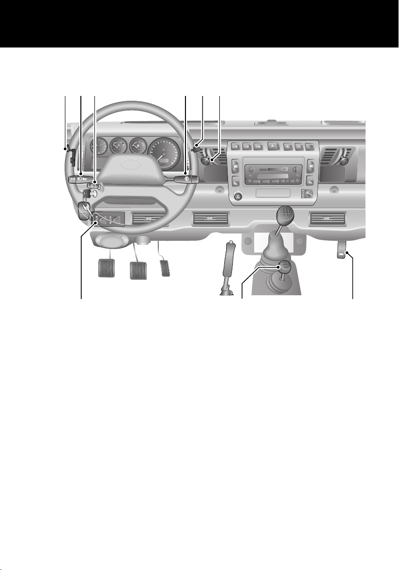
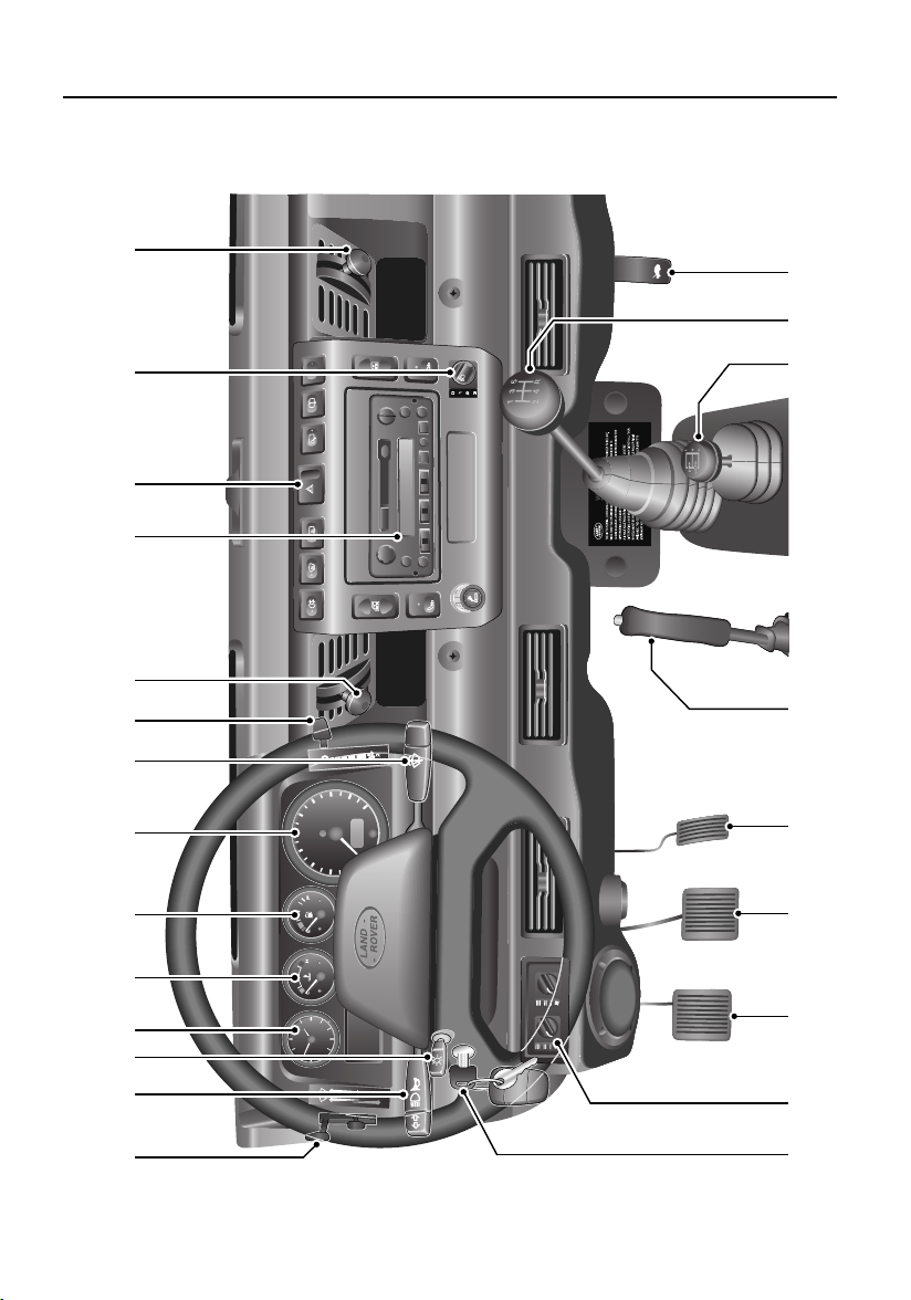
1. Fresh air vent control
2. Air blower control
3. Windscreen wiper/washer control
4. Lamps master switch
5. Direction indicators and horn control
2
3
1
8
9
6. Air temperature & distribution controls
7. Air conditioning controls
*
8. Transfer gear lever
9. Bonnet release lever
NOTE: The precise specification and location of the controls may vary according to territorial
requirements and from model to model within the vehicle range.
NOTE: For further information on the controls, see ‘FASCIA CONTROLS’, page 20.
5
Page 6
FASCIA SWITCHES
Quick Overview
1 2 3 4 5 6
7
8
H4963
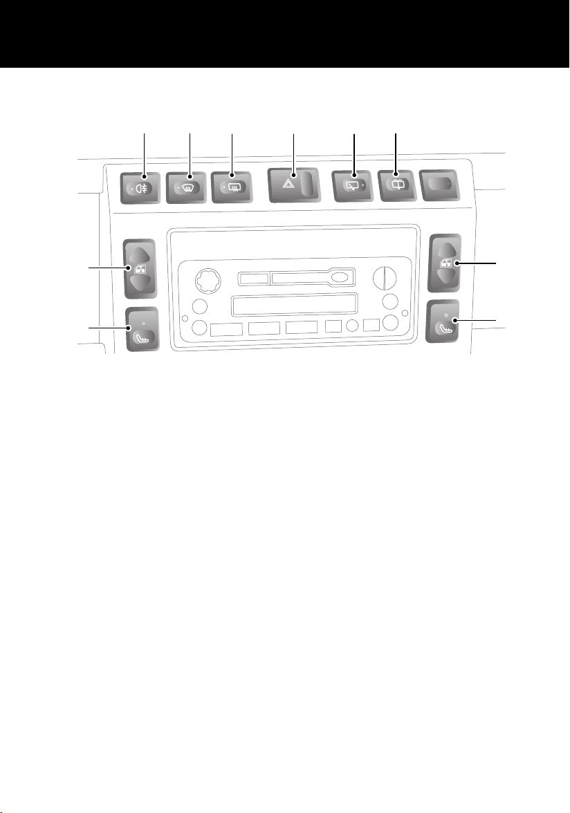
1. Rear fog lamps*
Press to operate (see ‘FOG LAMPS*’,
page 50)
2. Heated front screen
Press to operate (see ‘HEATED FRONT
SCREEN AND REAR WINDOW*’, page 59)
3. Heated rear window
Press to operate (see ‘HEATED FRONT
SCREEN AND REAR WINDOW*’, page 59)
4. Hazard warning lamps
Press to operate (‘HAZARD WARNING
LAMPS’, page 50)
5. Rear window wiper
Press to operate (see ‘REAR WINDOW
WIPER AND WASHER*’, page 52)
*
*
*
6. Rear window washer
Press to operate (see ‘REAR WINDOW
WIPER AND WASHER*’, page 52)
7. Electric windows
Press the appropriate switch to operate
the front left or right window (see
‘ELECTRIC WINDOWS *’, page 54)
8. Seat heaters
Press the appropriate switch to operate
the front left or right seat heater (see
‘HEATED FRONT SEATS*’, page 33)
*
*
*
7
8
6
Page 7
INSTRUMENT PANEL
Quick Overview
12
39
6
120
km/h
H4965
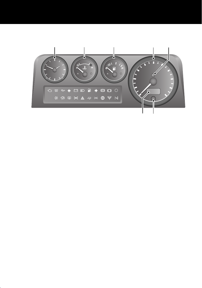
1. Speedometer
2. Engine immobilisation warning indicator
3. Total distance (odometer) and trip
recorder
4. Trip recorder reset button
567
40
ABS
TC
5. Fuel gauge
NOTE: When the fuel remaining drops to a
minimum of 9 litres, the low fuel warning
indicator will illuminate (see ‘INDICATOR
GROUPING’, page 45).
1
100
80
km/h
60
20
0
3
4
2
120
140
160
180
200
6. Temperature gauge
7. Clock
NOTE: For further information on the instrument panel, see ‘INSTRUMENT PANEL’, page 44.
7
Page 8
WARNING INDICATORS
Quick Overview
4
ABS
TC
120
km/h
1 2 3
5
H5333
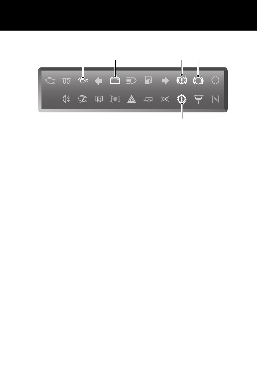
1. Low oil pressure (Red)
2. Battery charging (Red)
3. Handbrake (Red)
NOTE: If a warning indicator remains on or illuminates while driving, stop the vehicle and refer to the
relevant section of this handbook for advice.
NOTE: For further information on the warning indicators, see ‘INDICATOR GROUPING’, page 45.
4. Anti-lock braking system (Amber)*
5. Transmission oil temperature (Red)*
8
Page 9
Quick Overview
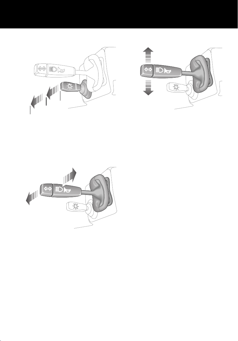
LAMPS AND INDICATORS
0
1
2
H3632
1. Side, tail and instrument panel lamps
2. Headlamps
Headlamp main and dipped beams
Direction indicators
H3629
Move the lever DOWN to indicate a LEFT turn,
and UP to indicate a RIGHT turn.
NOTE: For further information concerning
operation of the lamps and indicators, please
refer to ‘LAMPS’, page 48 and ‘DIRECTION
INDICATORS’, page 48.
H3630
Push the lever away from the steering wheel to
change headlamp beams.
To flash the headlamps, pull the lever part way
towards the steering wheel and release.
9
Page 10
Quick Overview
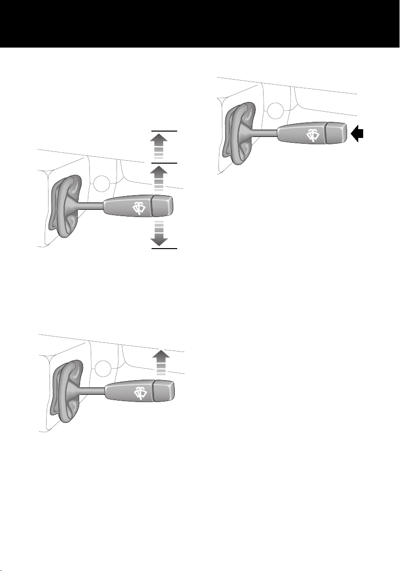
WIPERS AND WASHERS
The wipers and washers will only operate when
the starter switch is turned to position ‘I’ or ‘II’.
Windscreen wipers
3
2
H4969
1. Intermittent wipe
2. Normal speed wipe
3. Fast speed wipe
Single wipe
1
Windscreen washer
H3628
Press to operate.
NOTE: For further information concerning
operation of the wipers and washers, see
‘WINDSCREEN WIPERS’, page 51
and‘WINDSCREEN WASHER’, page 52.
H3626
Push the lever up against spring pressure and
release immediately.
10
Page 11
Quick Overview
USING YOUR HEATER
3
2
H4970
Maximum heating
• Air blower control (1) - fully down.
• Air distribution control (2) - midway.
• Temperature control (3) - fully down.
Demisting and defrosting
• Air blower control (1) - fully down.
• Air distribution control (2) - fully up.
• Temperature control (3) - fully down.
Maximum ventilation
• Air blower control (1) - fully down.
• Air distribution control (2) - fully down.
• Temperature control (3) - fully up.
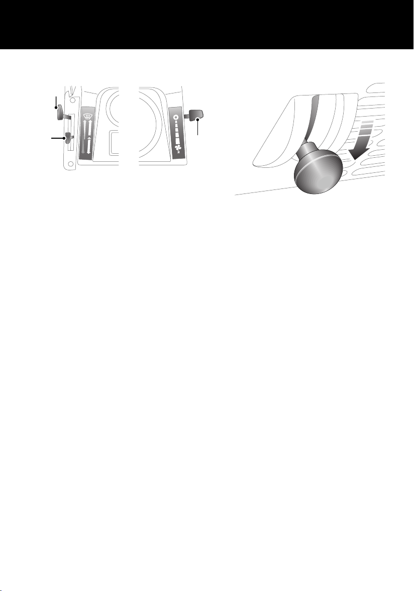
Fresh air vents
1
H3719
To open a vent, pull the knob out and push the
levers downwards.
NOTE: For further information concerning
heater controls, see ‘HEATER CONTROLS’,
page 57.
11
Page 12
Quick Overview
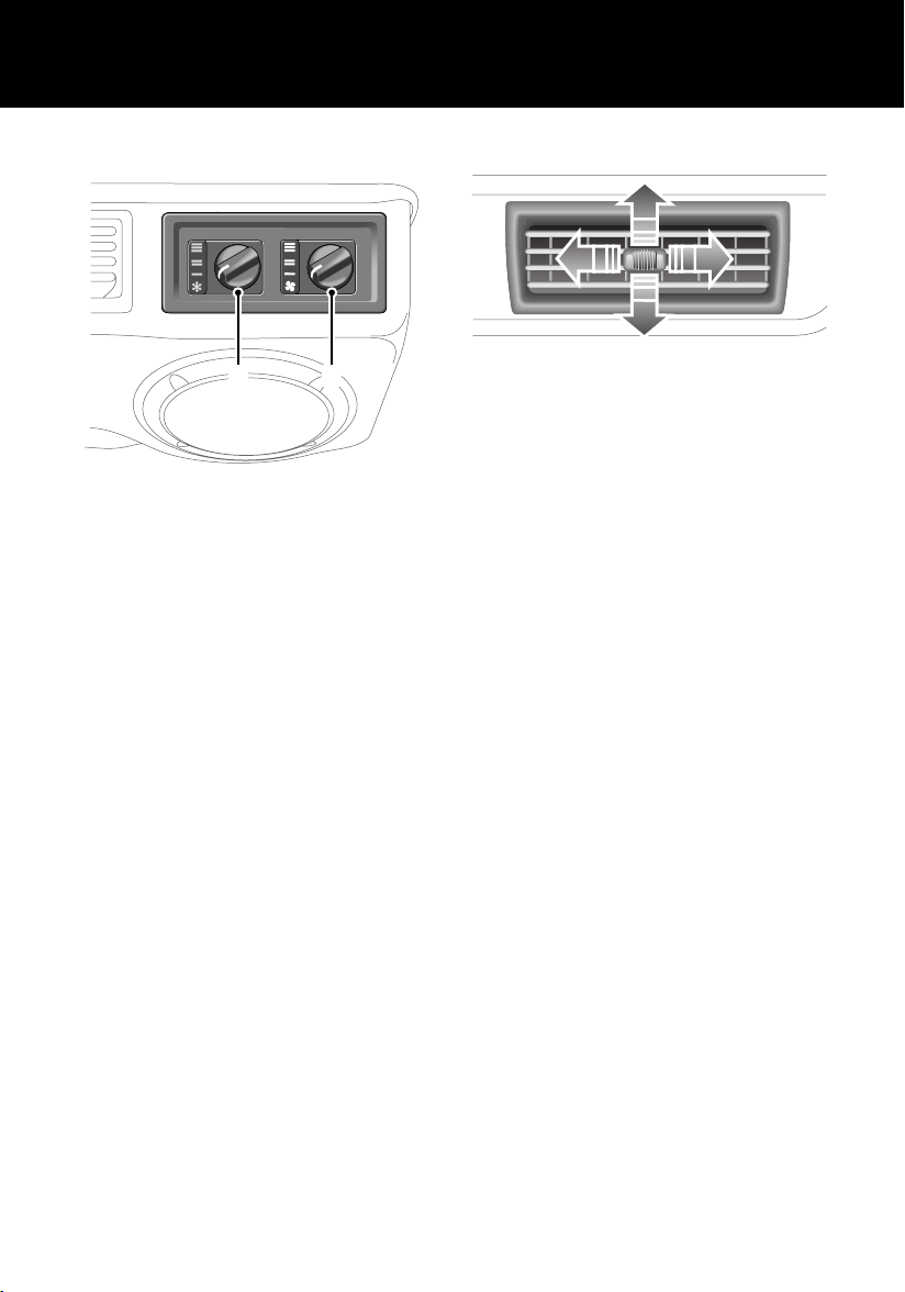
AIR CONDITIONING CONTROLS*
2
H3684
1. On/off blower control
2. Temperature control
1
Air conditioning vents
H3756
The adjuster in the centre of each vent can be
used to adjust volume and direction of air. To
cut off the supply of air from any particular
vent, slide the adjuster fully to the left.
NOTE: For further information concerning
heater controls, see ‘HEATER CONTROLS’,
page 57.
12
Page 13
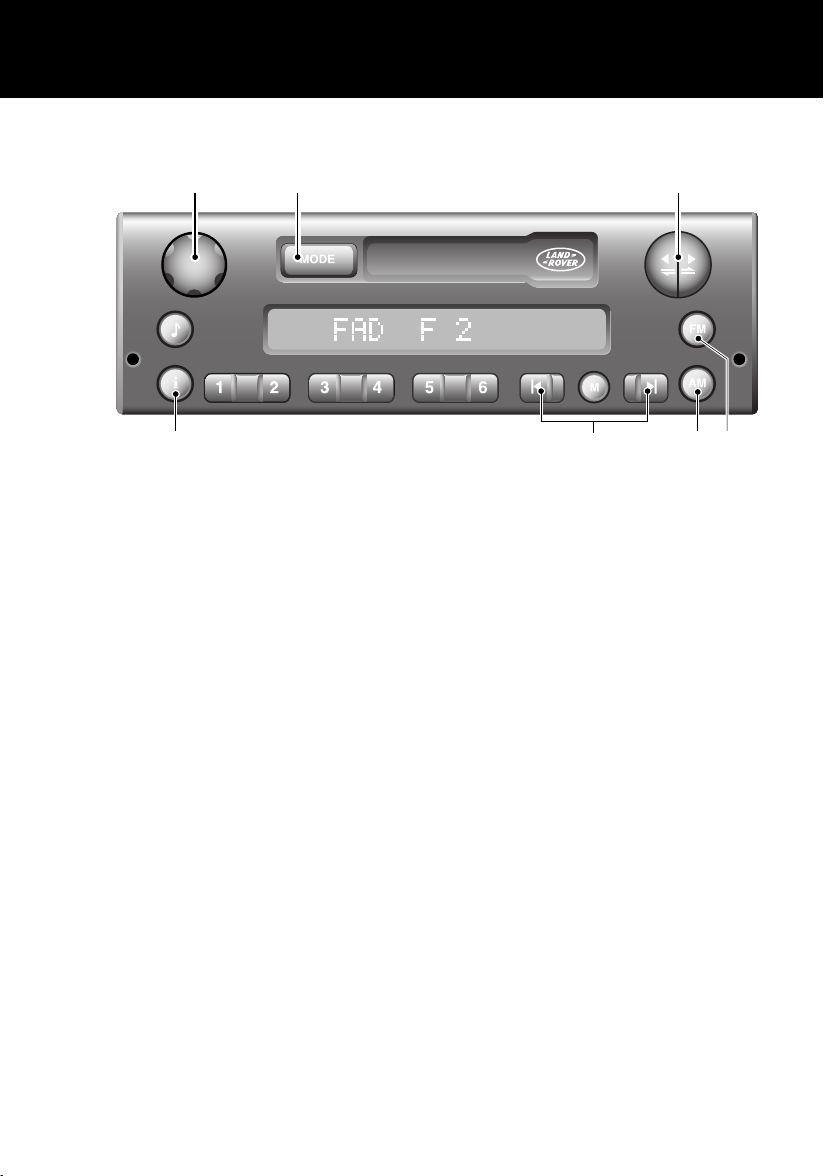
AUDIO SYSTEM CONTROLS*
1 2 3
Quick Overview
7
H4986
1. On/off volume control
2. Mode selector (MODE)
3. Tape controls
4. FM selector
NOTE: For more information concerning the operation of your audio system, see ‘AUDIO SYSTEM’,
page 175.
5. AM selector
6. Scan buttons
7. Traffic and news information
6
5 4
13
Page 14
Quick Overview
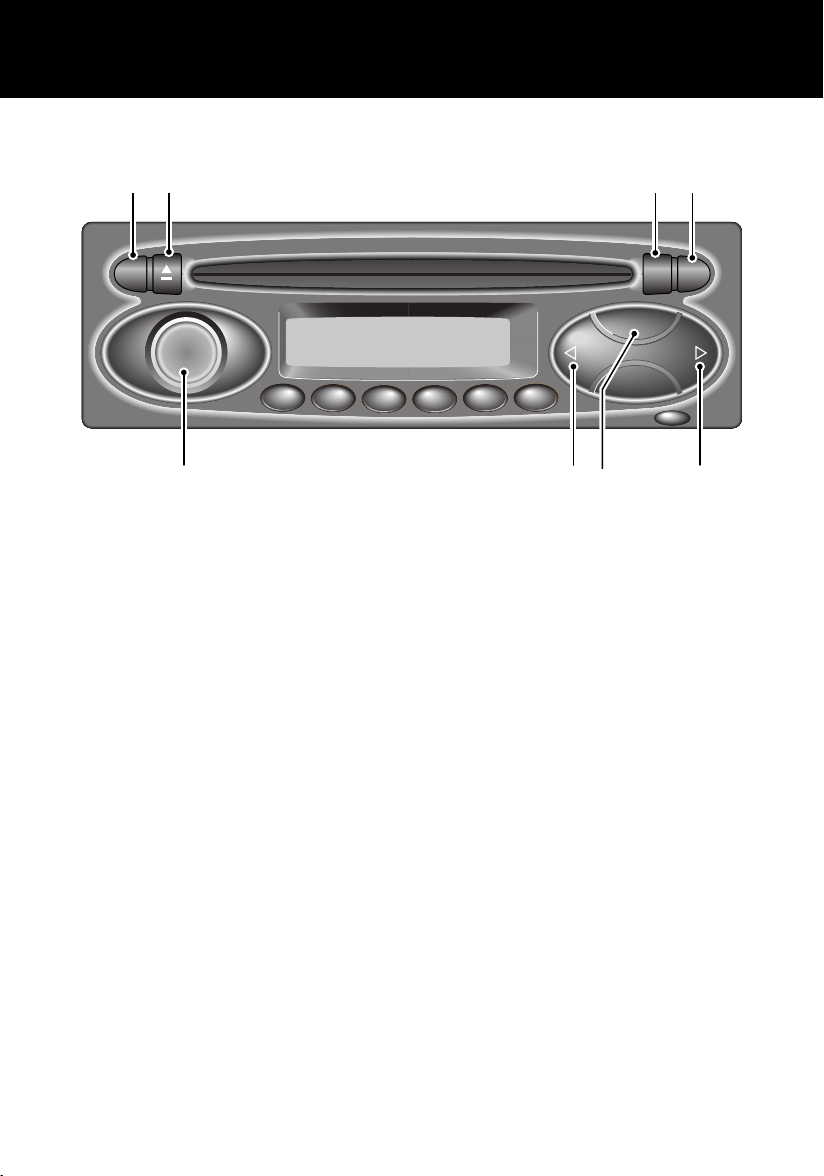
AUDIO SYSTEM WITH CD PLAYER CONTROLS*
162 3 4
RDS
FADE
BAL
BASS
TREB
1
2
34
i
CD
BAND
6
5
MENU
ICE1398
1. Radio Data System (RDS) selector
2. CD eject control
3. CD mode/repeat selector
4. Traffic and news information
5. Search controls
6. Waveband selector
7. Search controls
8. On/off and volume control
7 58
For more information concerning the operation of your audio system, see ‘AUDIO SYSTEM’,
page 175.
NOTE: Some music CD manufacturers are using data encryption to 'copy-protect' their recordings
and prevent the production of pirate copies. These CDs differ from the internationally agreed CD
audio standard, RedBook, a standard that serves as the operating basis for all CD players and
changers.
Copy-protected CDs may not play in your Audio unit or CD changer or may be played subject to
various limitations, e.g. sound quality may be impaired.
If you do experience a problem, try the CD in other players before contacting the CD vendor.
14
Page 15
Filling Station Information
Filling Station Information
Filling Station Information
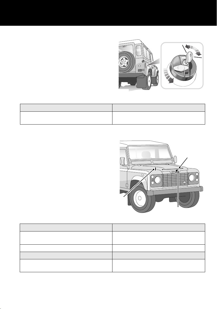
Fuel Filler
The fuel filler is located in the rear right-hand
body side.
Insert the key in the lock, turn it 90o clockwise
and allow any pressure inside the tank to
escape, before removing the cap.
NOTE: To replace the cap, the key should be
removed from the filler cap. The cap should be
turned clockwise until the ratchet is heard to
click at least three times. The cap is then locked.
Fuel type
All vehicles Diesel to EN 590 specification.
Opening the bonnet
Ensure that wipers are switched off and parked.
1. From inside the vehicle, pull the bonnet
release handle located on the right hand
side of the fascia at knee height.
2. Lift the bonnet safety catch lever.
3. Raise the bonnet and support it on the
stay.
H5253
NOT compatible with Bio-Diesel fuels
3
1
H5252
Engine oil top up
Td5 engines Castrol 5W/30 oil to ACEA: A1 and B1
specification.
Tdi engines Castrol 10W/40 oil to ACEA: B2 specification.
Cooling system top up
All vehicles 50% mix of fresh water and Castrol Anti-freeze
SF or Texaco XLC.
15
2
Page 16

Filling Station Information
Tyre pressures
Air pressure naturally increases in warm tyres (after the vehicle has been driven for a while). if you
have to check warm tyres, you should expect the pressures to have increased between 30 and 40 kPa
(4 and 6 lbf/in2). In this circumstance, NEVER let air out of the tyres in order to match the
recommended pressures.
All loading conditions
90 Models Front 197 (28)
Rear 262 (38)
110 Models Front 197 (28)
Rear 338 (48)
130 Models Front 309 (44)
Rear 457 (65)
Goodyear G90 750 R16C
10 ply rating radial
Front 220 (32)
Rear 410 (60)
Pressure - kPa (lbf/in2)
16
Page 17

General Information
General In formati on
WARNINGS IN THIS HANDBOOK
WARNING
Safety warnings are included in this
handbook. These indicate either a procedure
which must be followed precisely, or
information that should be considered with
great care, in order to avoid the possibility of
personal injury or serious damage to the
vehicle.
HANDLING CHARACTERISTICS
WARNING
Your vehicle has a higher ground clearance
and, hence, a higher centre of gravity than
ordinary passenger cars. This will result in
different handling characteristics.
Inexperienced drivers should take additional
care, particularly in off-road driving
situations and when performing abrupt
manoeuvres on unstable surfaces.
SYMBOLS USED
The following symbols used within the
handbook call your attention to specific types of
information.
This recycling symbol identifies those
items that must be disposed of safely in
order to prevent unnecessary damage to the
environment.
*An asterisk appearing within the text,
identifies features or items of equipment that
are either optional, or are only fitted to some
vehicles in the model range.
17
Page 18
General Information
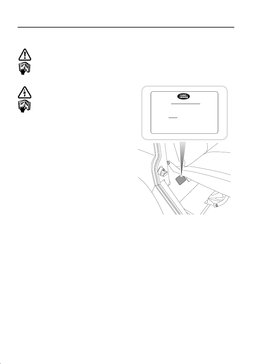
WARNING LABELS ATTACHED TO THE
VEHICLE
Warning labels attached to your vehicle
bearing this symbol mean: DO NOT
touch or adjust components until you
have read the relevant instructions in
the handbook.
Warning labels showing this symbol
indicate that the ignition system utilises
very high voltages. DO NOT touch any
ignition components while the starter
switch is turned on.
WARNING LABELS
Labels are attached to your vehicle at several
positions. These are applied to draw your
attention to important subjects such as tyre
pressures, tow bar usage, airbags, roll over
risk, engine compartment hazards, etc,
IMPORTANT
BEFORE JACKING VEHICLE
1. ENGAGE DIFF. LOCK. (i.e. WARNING
LIGHT MUST BE ILLUMINATED
PRIOR TO SWITCHING OFF IGNITION.)
2. APPLY HANDBRAKE.
3. CHOCK WHEELS
H4730
It is important that you are familiar with these
subjects to ensure that your vehicle and its
features are used safely. Using the index at the
back of this handbook, refer to the relevant
topic for more information.
18
Page 19

Keys and Remote Controls
Controls and Instruments
Keys and Remote C ontrols
KEYS AND REMOTE CONTROLS
You have been supplied with two remote
controls and two sets of keys, comprising:
• A black key for operating the starter switch
and door locks.
• A smaller metal key to operate the fuel filler
cap lock.
The starter key number is stamped on a tag
attached to the key ring. Check that the key
number has been entered in the space provided
on your Security card.
If the remote control is lost, contact a Land
Rover Dealer/Authorised Repairer, who can
supply a replacement unit.
WARNING
Keep the Security card and spare remote
control and keys in a safe place - NOT IN THE
VEHICLE.
19
Page 20
Fascia Controls
H5004
FASCIA CONTROLS
11 12 13 14
10
Fascia Controls
160
180
140
200
120
100
km/h
80
0
60
20
40
39
6
12
2 3 4 5 6 7 8 9
1
22 21 20 19 18 17 16 15
23
20
Page 21

Fascia Controls
FASCIA CONTROLS KEY
1. Air temperature and distribution controls
2. Direction indicators and horn control
3. Master lamp switch
4. Clock
5. Temperature gauge
6. Fuel gauge
7. Speedometer
8. Windscreen wiper/washer control
9. Air blower control
10. Fresh air vent control
11. Audio system
12. Fascia switches
13. Headlamp levelling switch
14. Fresh air vent control
15. Bonnet release lever
16. Main gear lever
17. Transfer gear lever
18. Handbrake
19. Accelerator pedal
20. Brake pedal
21. Clutch pedal
22. Air conditioning controls
23. Starter switch
*
NOTE: The precise specification and location of the controls may vary according to territorial
requirements and from model to model within the vehicle range.
21
Page 22
Locks and Alarms
Locks and Alarms
ALARM SYSTEM*
Your vehicle is fitted with a sophisticated
electronic anti-theft alarm and engine
immobilisation system. In order to ensure
maximum security and operating convenience,
you are strongly advised to gain a full
understanding of the alarm system, by
thoroughly reading this section of the
handbook.
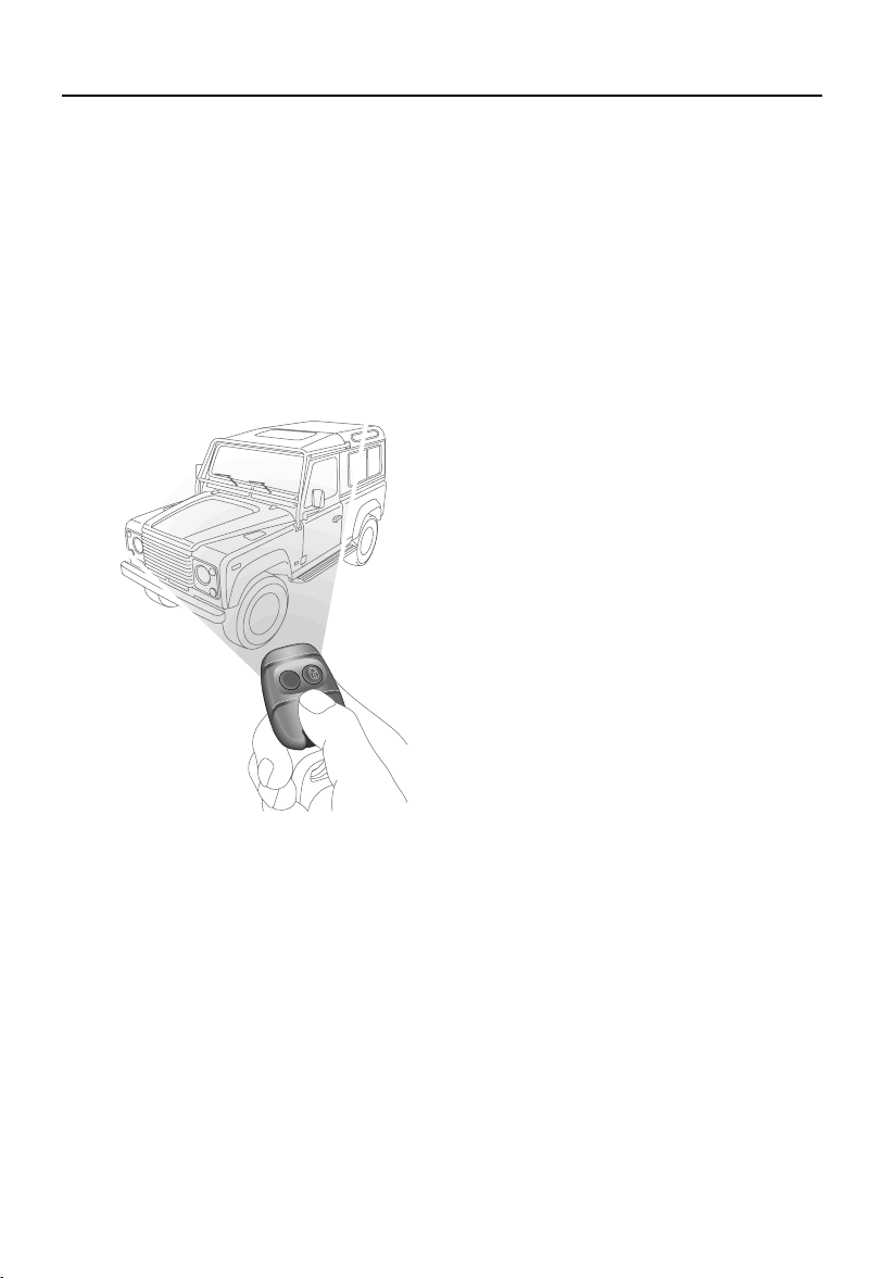
Using the remote control
H3619
While it is not necessary to point the remote
control at the vehicle, the remote control must
be within range of the vehicle when a button is
pressed. Note that the operating range may
vary depending upon remote control battery
condition and may sometimes be limited by
physical and geographical factors beyond your
control. From a security point of view, it may
not be wise to unlock unless you are within a
few feet of the vehicle.
Vehicles with central door locking
Locking with the remote control:
Press the lock (padlock symbol) button once:
• all doors are locked (including the tail door)
• engine immobilised
• perimetric alarm activated (protects the
doors and bonnet)
• interior space protection activated
The direction indicator lamps flash three times
to confirm that the vehicle is secure and the
anti-theft alarm indicator (in the instrument
panel) starts to flash.
Locking with the key:
Insert the key and turn the driver’s door lock
towards the rear of the vehicle:
• all doors locked (including the tail door)
• engine immobilised
• NO PERIMETRIC ALARM OR INTERIOR
SPACE PROTECTION
The anti-theft alarm indicator (in the instrument
panel) starts to flash after 30 seconds to show
that the engine is immobilised.
Unlocking with the remote control:
Press the unlock (PLAIN) button once to
disarm the alarm and unlock the doors.
The direction indicator lamps flash once and
the interior lamps illuminate.
Unlocking with the key:
While all the doors can be unlocked using the
key in the driver’s door lock, this method is NOT
RECOMMENDED - depending on the
specification of the vehicle the alarm may not
be disarmed.
*
22
Page 23
Locks and Alarms
Vehicles without central door locking
Locking and unlocking:
Each door lock must be operated individually,
using the key. The remote control will NOT
operate the door locks. Turn the key towards
the rear of the vehicle to lock and towards the
front to unlock.
Arming & disarming the alarm:
Press the lock button on the remote control to
arm the alarm.
• Perimetric protection protects the doors
and bonnet.
• Interior space protection is activated.
• Engine is immobilised.
Provided the doors and bonnet are securely
closed, the direction indicators will flash three
times and the anti-theft alarm indicator in the
instrument panel will start to flash.
To disarm the alarm, press the unlock (PLAIN)
button on the remote control; the direction
indicators will flash once and the interior lamps
illuminate.
Door sill locking buttons
From inside the vehicle, each door can be
individually locked by depressing the
appropriate sill locking button.
H3664
WARNING
DO NOT depress the sill buttons as a means of
locking the doors from outside the vehicle
(this practice - known as ‘slam locking’ - is
NOT recommended, because keys can be
locked inside accidentally).
On vehicles with central door locking, operation
of the driver’s door sill locking button locks all
the other doors too. However, engine
immobilisation and interior space protection
are suspended unless the remote control lock
button is pressed as well.
NOTE: Slam locking, as described above, is
prohibited on vehicles with central door
locking.
23
Page 24

Locks and Alarms
2
Anti-theft alarm indicator
100
120
80
60
40
20
0
H3662
140
160
180
200
The indicator lamp in the speedometer
(arrowed in illustration) provides information
about the status of the alarm system, as
follows:
When the alarm is armed:
The lamp flashes rapidly while the alarm is
arming itself. After 10 seconds, the lamp
adjusts to a slower frequency and continues to
flash as an anti-theft deterrent until the alarm is
disarmed.
If the engine is immobilised (even though the
alarm has been disarmed):
The lamp flashes slowly until the engine is
remobilised.
Mislock
If a door is not fully closed when the remote
control lock button is pressed, the hazard
warning lamps will fail to flash, indicating a
mislock. In this case, the alarm system will not
be fully armed and on vehicles with central door
locking, none of the doors will lock.
As soon as the open aperture is closed, the
hazard warning lamps will flash and the
anti-theft alarm indicator lamp will resume
flashing to confirm that the system has
returned to a fully armed state.
NOTE: If a mislock occurs as a result of an open
door, interior space protection will not be
activated.
NOTE: If a mislock occurs as a result of an open
bonnet, the door apertures will still be protected
by the alarm system and interior space
protection will be active.
If the alarm sounds
If the alarm is triggered, the alarm sounder or
vehicle horn will sound for 30 seconds before
switching off and resetting itself to the same
protection status that existed prior to the alarm
being triggered. The alarm can be triggered up
to three times before needing to be reset.
If the alarm has been triggered:
The lamp will flash rapidly when the alarm is
disarmed until the starter switch is turned to
position II.
If the remote control battery power is low:
The lamp will flash rapidly during the initial
10 seconds after the remote control has been
used, while the alarm system is arming.
If the driver’s door is open:
The lamp illuminates for 10 seconds, before
adjusting to slow frequency flashing.
To silence the alarm, press either button on the
remote control.
NOTE: While the alarm is sounding, the hazard
warning lamps will flash to provide a visual
alarm.
24
Page 25

Locks and Alarms
INTERIOR SPACE PROTECTION*
H3597
Interior space protection is designed to protect
the interior of the vehicle from intrusion (entry
by a thief through a smashed window, for
example). Twin sensors monitor the interior
space and activate the alarm if air movement is
detected in the passenger compartment.
Using the remote control:
Interior space protection is activated
automatically whenever the remote control is
used to set the alarm and can ONLY be
deactivated with the remote control.
Key operation:
On vehicles fitted with central door locking,
using the key to arm the alarm will NOT activate
(or deactivate) interior space protection.
NOTE: Interior space protection cannot be
activated if a door is open, or if the starter
switch is turned on.
Interior protection will not operate for the first
15 seconds after the alarm is set.
Vehicles without central door locking
To disable interior space protection when
setting the alarm, use the following procedure:
1. Open the driver’s door.
2. With the driver’s door open, use the
remote control to arm the alarm in the
normal way.
3. Close the driver’s door (the hazard
warning lamps flash three times and the
anti-theft indicator lamp commences
flashing rapidly).
The alarm system is now armed with interior
protection disabled.
NOTE: Never activate interior space protection
if windows or sunroof are to be left open, or if
passengers or animals are to be left inside the
vehicle - any movement will activate the alarm.
25
Page 26
Locks and Alarms
ENGINE IMMOBILISATION
Engine immobilisation is an important aspect of
the security system, and includes a feature
known as ‘passive immobilisation’. This is
designed to safeguard the vehicle from theft,
should the driver forget to lock the doors or arm
the alarm. Engine immobilisation is automatic
whenever any of the following conditions
occurs:
• The vehicle is locked using remote control
or key.
• Thirty seconds after the starter switch has
been turned off AND the driver's door
opened.
• Five minutes after the starter switch is
turned off, or the alarm system is disarmed.
The engine is re-mobilised when the vehicle is
unlocked using the remote control. However, if
no further action - such as ignition being turned
on - takes place within the next five minutes,
passive immobilisation will occur.
The engine immobilisation system relies on the
remote control to re-mobilise the engine. Look
after the remote control at all times, protecting
them from loss, damage and battery discharge.
If the engine has immobilised passively,
re-mobilisation will occur when the starter
switch is turned to position ‘II’, provided the
remote control is on the same ring as the key
and in close proximity to the switch.
• ALWAYS keep the remote control on the
same ring as the key.
• NEVER attach both remote controls to the
SAME key ring.
Any attempt to start the engine while it is
immobilised, will cause the engine
immobilisation warning indicator (in the
speedometer) to flash.
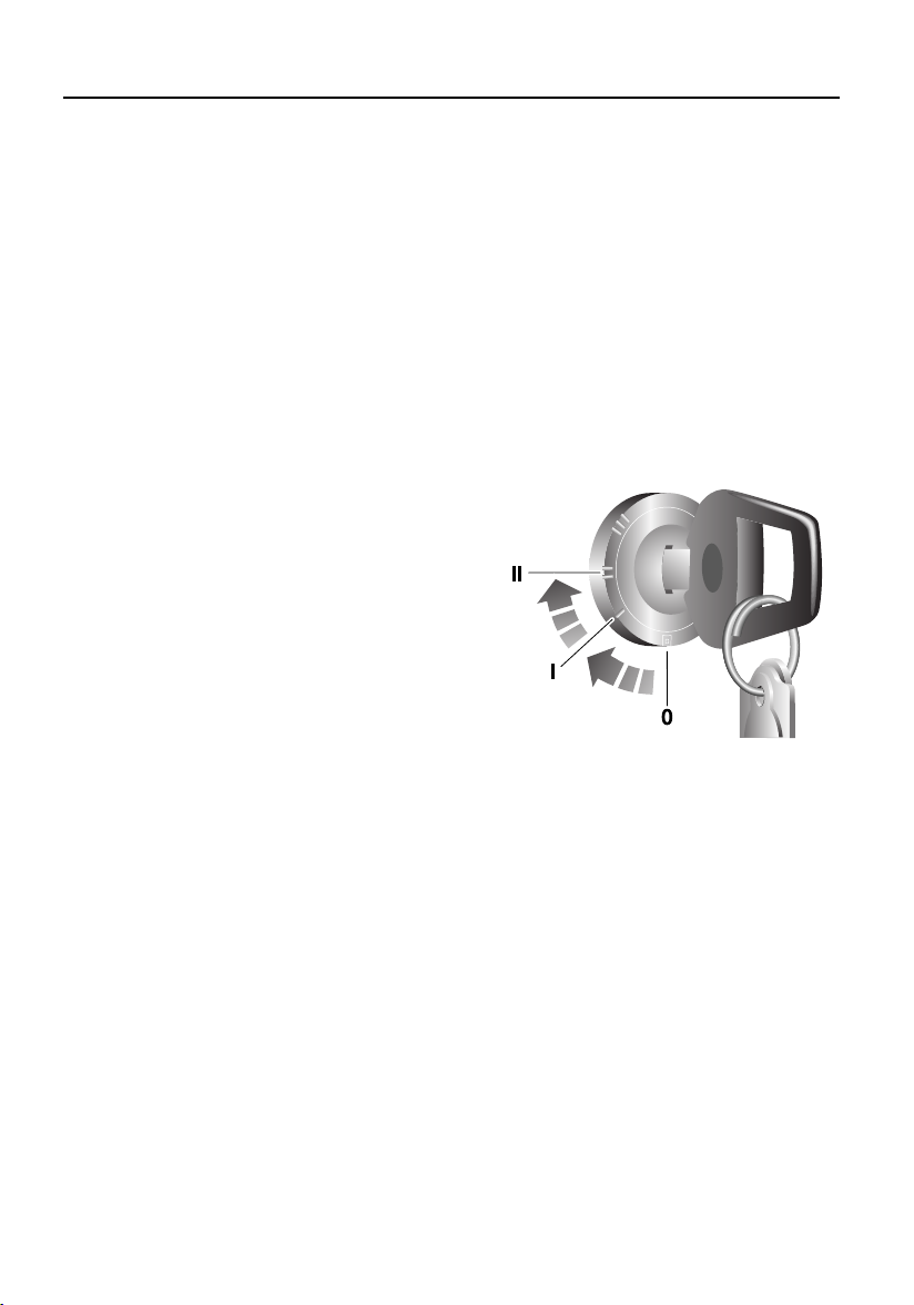
Emergency key access
If the remote control is damaged, or fails to
operate, the engine can be re-mobilised by
using the starter key to enter a unique four
number emergency key access code. The code
is recorded on the Security card and is entered
as follows:
If your remote control is lost or inoperative, it is
impossible to disarm the alarm. As soon as the
door is opened, the alarm will sound
(continuously for up to three 30-second
periods), and continue while the code is being
entered.
H6631
1. Remove the remote control from the key
ring and keep the remote control well
away from the starter switch when
entering the code.
2. From inside the vehicle, with the driver’s
door closed, immediately insert the key
into the starter switch and turn to position
‘II’. Hold this position until the alarm
sounds, then switch off and open and
close the driver’s door.
3. Turn the starter switch to position ‘II’ the
required number of times to enter the first
digit of the code (if the first digit is 4, turn
the key to position ‘II’ and then back to ‘0’
four times).
4. Open and close the driver’s door (this will
enter the first digit of the code).
26
Page 27

Locks and Alarms
5. Turn the starter switch to position ‘II’ and
back to ‘0’ the required number of times to
enter the SECOND digit of the code.
6. Open and close the driver’s door again.
7. Turn the starter switch to position ‘II’ and
back to ‘0’ the required number of times to
enter the THIRD digit of the code.
8. Open and close the driver’s door again.
9. Turn the starter switch to position ‘II’ and
back to ‘0’ the required number of times to
enter the FOURTH digit of the code.
10. Finally, open and close the driver’s door
one more time.
If the code has been entered correctly, the
anti-theft indicator will extinguish, the alarm
will stop sounding and the engine can be
started.
If an incorrect code has been entered:
If the code is entered incorrectly, the alarm
sounder will sound twice, the anti-theft
indicator lamp will continue to illuminate, and
the engine will fail to start. Before entering the
code again, turn the starter switch to position
‘II’ and hold in this position for 5 seconds.
After three failed entry attempts, the security
system invokes a delay period of 30 minutes
during which the system will not accept any
further attempts to enter a code.
Memorise the emergency key access code or
keep the Security card on your person in case
of emergencies. NEVER leave the card in the
vehicle.
REMOTE CONTROL BATTERY
The battery should last for approximately
three years dependent upon use. When the
battery needs replacing it will be apparent from
the following symptoms:
• The remote control will only work every
other operation while disarming.
• The hazard warning lamps will not flash
when the alarm is disarmed.
• DO NOT remove a battery until you are ready
to install the replacement.
• The engine will immobilise five minutes
after the key is removed from the starter
switch (or 30 seconds after the starter has
been switched off and the driver’s door
opened). If remote control battery
replacement is NOT completed within this
period, the emergency key access code will
have to be entered before the remote control
can be synchronised.
Always fit a Land Rover STC 4080 or a
Panasonic CR2032 replacement battery
(available from a Land Rover Dealer/Authorised
Repairer).
WARNING
The remote control contains delicate
electronic circuits and must be protected from
impact and water damage, high temperatures
and humidity, direct sunlight and the effects
of solvents, waxes and abrasive cleaners.
27
Page 28
Locks and Alarms
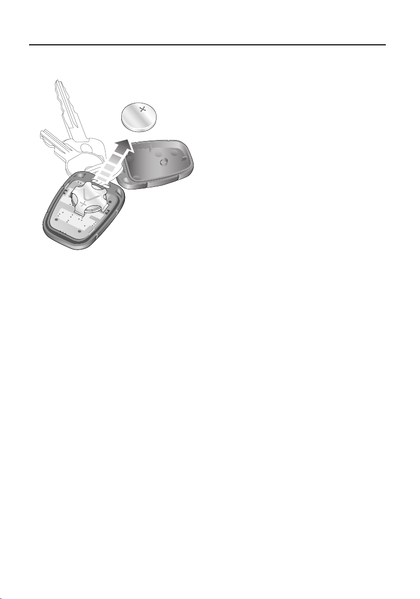
Battery replacement
H3663
1. Unlock the vehicle and disarm the alarm
system.
2. Turn the starter switch to position ‘II’, then
turn to position ‘0’ and remove the key.
3. Carefully prise the remote control apart;
start from the key ring end using a coin or
small screwdriver. Avoid damaging the
seal between the two halves of the case
and DO NOT allow dirt or moisture to get
inside the remote control.
4. Slide the battery out of its clip, taking care
to avoid touching the circuit board or the
contact surfaces of the clip.
5. Press and hold one of the buttons for at
least five seconds (this will drain any
residual power from the remote control).
6. Fit the new battery, ensuring that correct
polarity is maintained (‘+’ side facing up).
Finger marks will adversely affect battery
life; if possible, avoid touching the flat
surfaces of the battery and wipe them
clean before fitting.
7. Press the two halves of the remote control
firmly together and ensure that both
halves are fully joined, to prevent dirt or
moisture from entering the remote
control.
8. Operate the PADLOCK symbol button at
least four times within range of the vehicle
to synchronise the remote control.
9. Press the unlock button once to unlock the
vehicle.
The remote control is now ready for use.
28
Page 29
Locks and Alarms
ALARM OR REMOTE CONTROL
DIFFICULTIES
If the alarm goes off unexpectedly:
Ensure all the windows and sunroof are closed,
or if they need to be left open, disable interior
space protection.
If the alarm goes off when a door is opened:
Disarm the alarm with the remote control
before unlocking. If the remote control has
failed, enter the emergency key access code
(refer to ‘Emergency key access’, page 26).
If the starter will not operate:
Ensure the remote control is on the same key
ring as the starter key. If it still will not operate,
consult a Land Rover Dealer/Authorised
Repairer.
If the hazard warning lamps fail to flash when
the alarm is armed:
A door or bonnet is partially opened - close the
open aperture and try again.
Battery disconnection
Your vehicle is equipped with a battery
backed-up sounder
anti-theft siren if the vehicle battery is
disconnected.
*, which operates as an
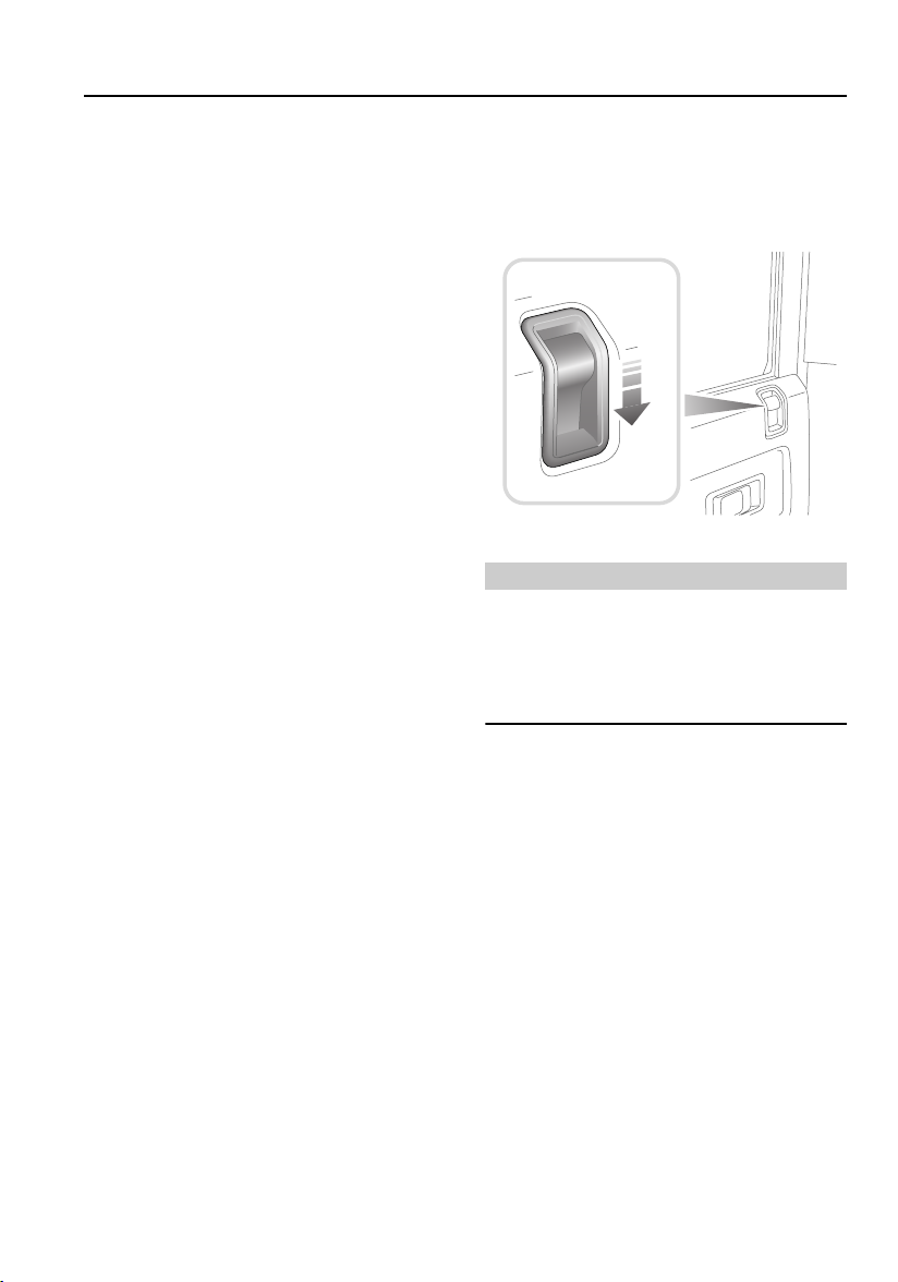
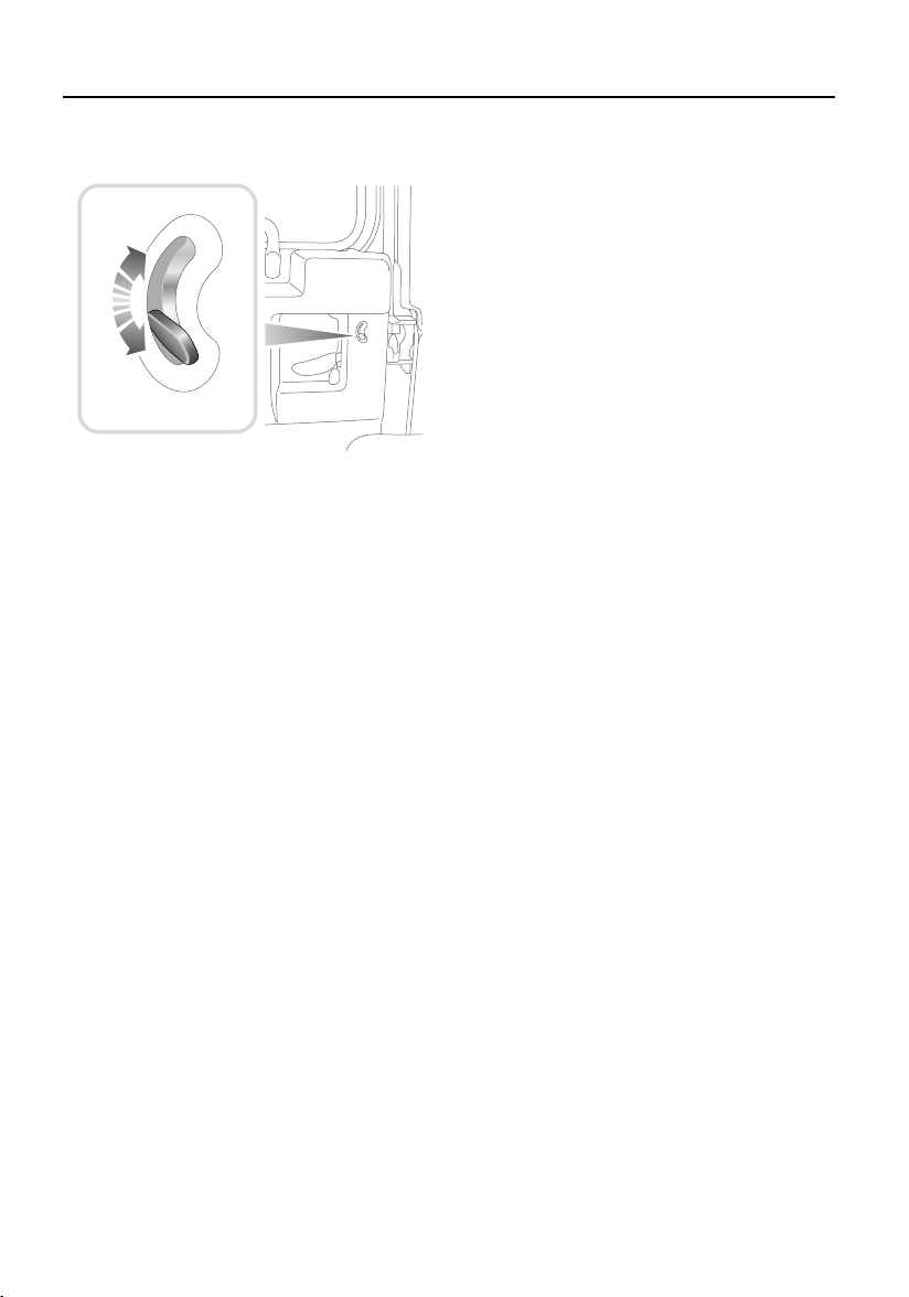
CHILD-PROOF LOCKS*
H3661
Move the locking levers on the rear doors down
to engage the child locks.
With the child-proof locks engaged, the rear
doors cannot be opened from inside the
vehicle, thereby avoiding the risk of a door
being opened accidentally while the vehicle is
moving.
WARNING
NEVER leave children unsupervised in the
vehicle.
Before disconnecting the vehicle battery, it is
ESSENTIAL to refer to, in order to prevent the
alarm from sounding.
If the vehicle battery is disconnected for any
reason, the status of the security system prior
to disconnection will be memorised and
automatically reset when the battery is
reconnected.
29
Page 30
Locks and Alarms
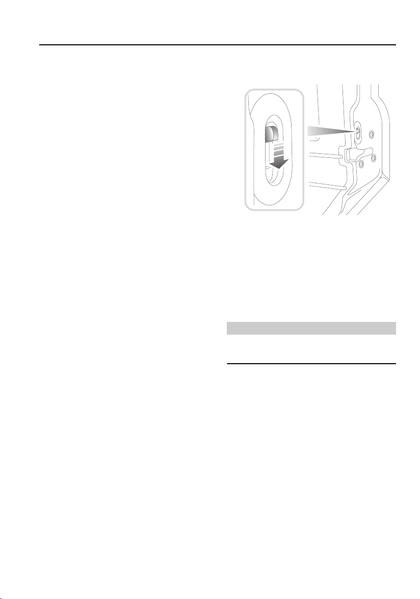
TAIL DOORS*
H3618
From outside, use the key to lock and unlock
the taildoor. From inside and with the door
closed, push the locking button up to lock and
down to unlock (see illustration).
30
Page 31

Seats
FRONT SEATS
Seats
WARNING
To avoid the risk of loss of control and
personal injury, DO NOT adjust the driver's
seat or head restraint while the vehicle is in
motion.
Sitting correctly
The seats, head restraints, and seat belts all
contribute to the protection of the occupants.
Optimal use of these components will give you
more protection. Therefore, observe the
following points:
• Sit in the most upright position with the
base of your spine as far back as possible
and the backrest reclined not more than ’A’
O
.
30
• Adjust the head restraints so that the top of
the head restraint is level with the upper
portion of the head.
• Do not move the driver’s seat too close to
the steering wheel. Ideally, a minimum
distance ’B’ of at least 254 mm (10 in)
between the centre of the breastbone and
the steering wheel cover is recommended.
The driver should hold the steering wheel
with slightly bent arms. The legs should also
be slightly bent so that the pedals can be
pressed to the floor.
• The seat belt should rest in the centre of the
shoulder. The lap part should fit tightly
across the hips and not on the stomach.
A
B
H6632L
Forward/backward adjustment
Make sure your driving position is comfortable
and enables you to maintain full control of the
vehicle.
H3708
Lift the bar at the front of the seat to slide the
seat forward or back. Ensure the seat is locked
in position before driving.
31
Page 32

Seats
Seat back adjustment
H3707
Lift the lever on the side of the seat and lean
backwards or forwards to achieve the desired
angle, then lower the lever to lock.
WARNING
DO NOT travel with the seat backs reclined
steeply rearwards. Optimum benefit is
obtained from the seat belt with the seat back
angle set to approximately 30
upright (vertical).
o
from the
Seat cushion removal
H3709
WARNING
ENSURE that the seat cushion is securely in
place before driving.
The front seat cushions can be removed to
access the battery and secondary fuse box as
follows:
Pull up the front of the seat base to release it
from its retaining clips, then pull the cushion
forward to remove.
32
Page 33

Seats
When replacing, insert the lugs at the back of
the seat cushion into the corresponding holes
where the seat base meets the seat back, then
push firmly down on the front of the seat
cushion to secure in place.
NOTE: On cars equipped with seat heaters, an
electrical lead connects the heater unit in the
seat cushion with the vehicle wiring harness.
When removing the seat cushion care must be
taken to avoid straining or damaging the lead.
HEAD RESTRAINTS
H3710
Pull the head restraint up or down until the
cushion is level with the back of the head.
WARNING
Head restraints are designed to support the
back of the head (NOT THE NECK), and to
restrain rearward movement of the head in
the event of a collision. The restraint must be
positioned level with the head to be effective.
HEATED FRONT SEATS*
H3670
With the starter switch turned on, press the
switches to operate the heating elements in
either the driver's or front passenger seat (the
indicator lamp in the switch illuminates). Press
a second time to switch off.
The seat heaters are thermostatically controlled
and operate intermittently to achieve and then
maintain a predetermined temperature between
26° - 36°C.
The seat heaters consume considerable power
from the battery. For this reason, they should
ONLY be operated while the engine is running.
NOTE: The centre front seat
with heating elements.
* is not equipped
33
Page 34

Seats
FOLDING THE REAR SEATS
WARNING
DO NOT adjust the seats while the vehicle is
in motion.
When re-erecting the 60/40 split rear seats
ensure that the seat stands are properly
positioned.
When the seat is erected, the latching
mechanism should be visually checked and
physically tested to ensure that the latch is
secure before driving.
Before folding the rear seats:
• Slide the front seats forward.
• Ensure that the outer rear seat belts are
correctly stowed.
• Pass the seat belt locks through the junction
of the backrest and the cushion and into the
loadspace.
NOTE: When unfolding the rear seats, the seat
belt locks must be passed back through the
junction of the backrest and the cushion.
*,
60/40 split rear seats*
1
2
3
4
H3712
1. Pull up the release catch (see inset).
2. Fold the backrest forward.
3. Lift and fold the seat base forward.
4. Fold away the seat stand.
34
Page 35

Seats
Individually split rear seats*
NOTE: The centre seat cannot fold until both
outer seats have been folded.
H3740
Outer seats:
1. Release the catch (see first inset).
2. Fold the backrest forward.
3. Slide back the bolt (see second inset).
4. Lift and fold the seat base forwards.
H3741
35
Page 36

Seats
Centre seat:
1. Release the catch - as stage ‘1’ for the
outer seats.
2. Fold the backrest forward.
3. Lift and fold the seat base forwards.
When returning the backrest to the upright
position, ensure that both the seat base and the
backrest of all three seats are securely latched
in place before driving.
H3720
36
Page 37

Seats
Rear compartment folding seats*
WARNING
When the seat is in use, the steel support
must be angled as shown in the illustration
(i.e. pointing away from the front of the seat,
with its foot angled into the floor where the
floor meets the side of the vehicle).
1. Unclip the restraining strap (see inset) and
fold down the seat base.
2. Position the steel seat support as shown
in illustration.
The steel supports can be folded flat against the
underside of the seat base when not in use. The
strap (see inset) should be used to secure the
seat base in the folded position when not in use.
Rear compartment bench seats*
H3714
H3713
These are fixed seats and cannot be folded. The
seat cushions are removable (see illustration).
37
Page 38

Seat Belts
Seat Belts
SEAT BELT SAFETY
The use of front and rear seat belts is
mandatory in most countries. Using seatbelts
saves lives. For maximum protection they
should be worn by all occupants whenever the
vehicle is in use.
WARNING
The seat belts fitted to the front and second
row seats are intended for use by adult sized
occupants. Each belt should be used by one
occupant only.
Lap or shoulder seat belts are provided for all
seat positions.
WARNING
Belts should not be worn with the
webbing/straps twisted.
Seat belts should be adjusted as firmly as
possible, consistent with comfort, to provide
the protection for which they are designed. A
slack belt will greatly reduce the protection
afforded to the wearer.
DO NOT allow front seat occupants to travel
with the seat backs reclined steeply
rearwards. Optimum benefit is obtained from
the seat belt with the seat back angle set to
approximately 30º from the upright (vertical)
position.
The inertia reel operation of the seatbelts allows
the wearer to move their upper bodies to reach
various controls. The seatbelt locks
automatically with rapid body movement, or in
the event of emergency braking.
WARNING
Observe the following precautions:
DO make sure ALL passengers are securely
strapped in at all times - even for the shortest
journeys.
Seat belts are designed to bear upon the bone
structure of the body and should be worn low
across the pelvis, chest, and shoulders, as
applicable. Wearing the lap section of the
belt across the abdominal area must be
avoided.
DO NOT wear seat belts over hard, sharp or
fragile items in clothing, such as pens, keys,
spectacles etc.
Ensure that all seat belts are worn correctly an improperly worn seat belt increases the
risk of death or serious injury in the event of a
collision.
Each belt assembly must only be used by one
occupant at a time. It is extremely dangerous
to put a belt around a child being carried on
an occupant’s lap.
Always replace a seat belt assembly that has
withstood the strain of a severe vehicle
impact, or if the webbing shows signs of
fraying or damage.
Where possible use the seat belts to secure
large items of luggage that are to be carried
on the seats - in the event of an accident,
insecure items become flying missiles
capable of causing serious injury. Take care
to ensure that no sharp edges are able to
come into contact with the seat belt.
Should the belt not retract and remain at it’s
static length, consult your Land Rover
dealer/authorised repairer immediately.
Care should be taken to avoid contamination
of the webbing with polishes, oils and
chemicals, and particularly corrosive
substances such as battery acid.
Cleaning may be carried out safely using mild
soap and water.
38
Page 39

Seat Belts
PREGNANT WOMEN
WARNING
Pregnant women must wear a correctly
positioned seat belt; it is safer for mother and
unborn child.
During pregnancy, women should wear the lap
belt across the hips below the baby, with the
diagonal belt passing across the shoulder,
between the breasts and to one side of the baby
- if in doubt, consult a doctor.
H5157
WARNING
Never place anything between you and the
seat belt in an attempt to cushion the impact
in the event of an accident. It can be
dangerous and reduce the effectiveness of the
seat belt in preventing injury.
SEAT BELTS
To minimise injury in the event of an accident,
it is important that seat belts are worn correctly.
Read the instructions below and ‘SEAT BELT
SAFETY’, page 38.
Fastening the inertia reel seat belts
H3715
Pull the belt over the shoulder and across the
chest and, ensuring that the webbing is not
twisted, insert the metal tongue plate into the
buckle nearest the wearer - a ‘CLICK’ indicates
that the belt is securely locked.
Seat belts are designed to bear upon the bony
structure of the body (pelvis, chest and
shoulders) and can only be worn safely with the
seats in a normal upright position - DO NOT
allow front seat occupants to travel with the
seat steeply reclined.
NOTE: In some circumstances, perhaps due to
the vehicle being on a slope, the automatic
locking mechanism may engage, preventing the
initial extension of the belt. This is not a fault ease the belt free and use it.
Releasing the belt
Press the RED button on the seat belt buckle.
39
Page 40

Seat Belts
Lap belts
CARING FOR SEAT BELTS
Regularly inspect the belt webbing for signs of
fraying, cuts and wear; also pay particular
attention to the condition of the fixing points
and adjusters.
DO NOT bleach or dye the webbing and avoid
contaminating the webbing with polish, oil or
chemicals (see ‘CLEANING THE INTERIOR’,
page 132).
Testing inertia reel belts
• With the seat belt fastened, give the
webbing near the buckle a quick upward
pull. The buckle must remain securely
locked.
• With the seat belt unfastened, unreel the
webbing to the limit of its travel. Check that
unreeling is free from snatches and snags
and then allow the belt to FULLY retract.
• Partially unreel the webbing, then hold the
tongue plate and give it a quick forward pull.
The mechanism must lock automatically
and prevent any further unreeling.
If a seat belt should fail any of these tests,
contact your dealer immediately.
H3716
To adjust, pull the slider along the belt and feed
the webbing through the buckle until the belt is
comfortably tight. Then, insert the metal tongue
plate into the buckle nearest the wearer - a
‘CLICK’ indicates that the belt is securely
locked. When not in use, the lap belts should be
fastened.
WARNING
Always replace a seat belt that shows signs of
webbing damage or has withstood the strain
of a severe vehicle impact.
40
Page 41

Child Restraints
Child Restraints
CHILD SEATS
WARNING
DO NOT use a forward-facing child seat until
a child is above the minimum weight of 9 kg
(20 lb.) and able to sit up unaided. Up to the
age of two a childs neck and spine are not
sufficiently developed to avoid injury in a
frontal impact.
The side-facing folding or fixed bench seats
fitted in the load carrying area of some
vehicles, are not suitable for fitting child
safety seats.
DO NOT allow a baby or infant to be carried on
the lap of an occupant. The force of a crash
can increase the effective bodyweight by as
much as thirty times, making it impossible to
hold onto the child. Children typically require
the use of a booster seat appropriate to their
age and size, thereby enabling the seat belts
to be properly fitted. This reduces the risk of
injury in a crash. Children could be
endagered in a crash if their restraints are not
properly secured in the vehicle.
The seat belts fitted to your vehicle are
designed for adults and larger children. It is
very important that all infants and children
under 12 are restrained in a suitable child safety
seat appropriate to their age and size (see table
below). Child safety seats approved for use in
your vehicle are available from your Land Rover
dealer/authorised repairer.
Only fit a child safety seat of a type approved for
the specific seating positions in your vehicle
(see table) and ensure the manufacturer's
fitting instructions are followed exactly.
NOTE: Crash statistics show that children are
safer when properly restrained in the rear
seating positions, than they are in the front.
DO NOT use a child seat that hooks over the
seat back. This type of seat cannot be
satisfactorily secured and is unlikely to be
safe for a child.
41
Page 42

Child Restraints
Defender 90 & 110 Station Wagons only
Mass Group
(As displayed on Child Resstraint
packaging)
0 = Up to 10 kg (0-9 months) U L X
0+ = Up to 13 kg (0-2 years) U L X
I = 9 to 18 kg (9 months - 4 years) U L X†
II & III =15 to 36 kg (4-12 years) U L X†
U = Suitable for ‘universal’ category restraints approved for this mass group.
L = Suitable for particular child restraints as listed below.
X = Seat position not suitable for children in this mass group.
† = Not suitable for the majority of child restraints which require a 3-point seat belt for
attachment, however, a child restraint may be used in these positions provided that it is
specifically designed and sold for use with a 2-point seat belt.
†† = seat back set vertically and seat moved fully backwards and then forwards 3 notches
Group O - Britax First Class (rearward facing), (Britax Cosy Tot)
Group O+ - Britax First Class (rearward facing), (Britax Cosy Tot)
Group l- Britax First Class (forward facing), Britax Duo Plus
Group ll & lll - Britax Kid
NOTE: Child restraint information given in the
table is correct at time of going to press.
However, availability of child restraints may
change. Please refer to your dealer for the latest
information.
Forward-Facing Seating Positions
Front
Passenger††
Rear Outboard Rear Centre
42
Page 43

Door Mirrors
Door Mirrors
EXTERIOR MIRRORS
NOTE: Objects viewed in exterior mirrors may
appear further away than they actually are.
Adjusting the mirrors
H3650
Move the mirror glass to the required position.
Folding the mirror body
Positioning the mirror for towing
H3652
To improve rear visibility when towing, the
mirrors can be folded outwards (see
illustration), so that the mirror stem is at 90º to
the side of the vehicle, increasing the field of
vision.
H3651
The door mirrors are designed to fold forwards
or rearwards on impact. They can also be folded
back towards the side windows into a ‘park’
position to enable the vehicle to negotiate
narrower openings.
43
Page 44

Instruments
INSTRUMENT PANEL
Instruments
12
39
6
120
km/h
H3724
8
1. Speedometer
Indicates road speed in kilometres per hour.
2. Anti-theft alarm indicator
Indicates the status of the alarm system (see
‘Anti-theft alarm indicator’, page 24).
3. Total distance (odometer) and trip recorder
Indicates the total distance or the individual
journey distance travelled by the vehicle.
4. Trip recorder reset button
Briefly press and release the button to change
the digital display between either the total
distance travelled, or the individual journey
distance. Press and hold the button to reset the
trip recorder to zero.
5. Fuel gauge
The pointer indicates the fuel level when the
starter switch is turned to position ‘II’.
NOTE: When the fuel remaining drops to a
minimum of 9 litres, the low fuel warning
indicator will illuminate (see ‘INDICATOR
GROUPING’, page 45).
567
40
ABS
TC
1
100
80
km/h
60
20
0
3
4
2
120
140
160
180
200
6. Temperature gauge
Once the engine coolant has reached its normal
operating temperature, the pointer should
remain between the BLUE and RED segments.
If the pointer moves towards the RED segment,
this indicates that the engine coolant is
becoming too hot. Should the pointer move
INTO the RED segment, severe engine damage
could occur. In this case, stop the vehicle as
soon as safety permits and allow the engine to
idle for five minutes in order to cool down - DO
NOT SWITCH OFF. Seek qualified assistance
before continuing.
7. Clock
For further information on setting the time on
the clock, see ‘CLOCK’, page 62.
8. Warning indicators
For further information on the functionality of
the warning indicators, see ‘INDICATOR
GROUPING’, page 45.
44
Page 45

Warning Indicators
INDICATOR GROUPING
120
km/h
H3723
Warning Indicators
ABS
TC
The location and specification of the warning
indicators may vary according to model and
market requirements.
WARNING
DO NOT drive if a RED warning indicator
remains on once the engine is running or
illuminates whilst driving.
Check engine - AMBER
Illuminates as a bulb and system
check when the starter switch is
turned on, and extinguishes as
soon as the engine is started. Illumination at
any other time indicates an
engine fault - if the indicator illuminates while
driving, avoid high speeds and seek qualified
assistance urgently.
Glow plug - AMBER
Illuminates when the starter switch
is turned to position ‘II’. Wait for
the indicator to extinguish before
starting the engine.
*
Low oil pressure - RED
Illuminates as a bulb check when
the starter switch is
turned to position ‘II’ and
extinguishes when the engine is started. If the
indicator remains on, flashes on and off, or
illuminates whilst driving, stop the vehicle as
soon as safety permits and SWITCH OFF
THE ENGINE IMMEDIATELY. Seek qualified
assistance before driving. Always check the oil
level when this indicator illuminates.
Direction indicators - GREEN
The left or right warning indicator
flashes in time with the
corresponding left or right
direction indicator lamps whenever they are
operated. If the warning indicator fails to flash,
or flashes very rapidly, this may indicate a bulb
failure in one of the direction indicator lamps.
If the hazard switch is pressed, both warning
indicators will flash in conjunction with the
direction indicator lamps.
Battery charging - RED
Illuminates as a bulb check when
the starter switch is turned to
position ‘II’ and extinguishes once
the engine is running. If it remains on, or
illuminates whilst driving, a fault is indicated.
Seek qualified assistance urgently.
45
Page 46

Warning Indicators
Headlamp main beam - BLUE
Illuminates when the headlamps
are switched to main beam.
Low fuel - AMBER
Illuminates when the fuel
remaining in the tank drops to a
minimum of 9 litres (2 gallons). If
the indicator illuminates, refuel at the first
opportunity.
Handbrake, brake fluid - RED
The indicator illuminates for about
3 seconds as a bulb check when
the starter switch is turned on. It
also illuminates when the handbrake is applied
with the starter switch in position ‘II’. The
indicator should extinguish when the
handbrake is fully released or shortly after the
electrical circuits are switched on. If the
indicator illuminates whilst driving, a fault with
the braking system is indicated. Stop the
vehicle as soon as safety permits and seek
qualified assistance before continuing.
Anti-lock braking system - AMBER
Illuminates for approximately 1
second as a bulb and system check
when the starter switch is turned to
position ‘II’, and briefly extinguishes before
coming on again. If the indicator does not
extinguish and then come on again, then a fault
occurred with the ABS system and you should
consult a qualified dealer at the earliest
opportunity. The warning indicator will remain
on until the vehicle is driven above
approximately 7 km/h (4 mph).
If the indicator remains on or subsequently
illuminates while driving, a fault has been
detected by the self monitoring system. This
means that full ABS control may not be
available and you should consult your dealer at
the earliest opportunity.
Traction Control - AMBER
Illuminates as a bulb check when
the starter switch is turned to
position ‘II’ and extinguishes after
approximately 3 seconds. The indicator
illuminates for a minimum of 2 seconds,
whenever traction control is operating.
*
*
If the warning indicator flashes (for at least
10 seconds) traction control has been
operating for too long and has temporarily shut
down to allow the system to cool - this will only
occur in extreme conditions.
If the indicator illuminates continuously, a fault
with the system is indicated; seek qualified
assistance.
46
Page 47

Warning Indicators
Rear fog lamps - AMBER*
Illuminates whenever the rear fog
lamps are on.
NOTE: In clear conditions, rear fog lamps can
dazzle other road users. Use ONLY when
visibility is severely restricted.
Engine immobilisation - RED
Flashes during any attempt to start
the engine when the engine is
immobilised.
Heated rear screen - AMBER*
Illuminates when the rear screen
heater is operating.
Differential lock - AMBER
Illuminates whenever the
differential is locked. If the
indicator remains on after the
differential lock is disengaged, transmission
‘wind-up’ may be present. Reversing for a short
distance and then going forward will usually
‘unwind’ the transmission. If the indicator
remains on, contact your dealer as soon as
possible.
Hazard warning lamps - RED
Illuminates in conjunction with the
direction indicator warning lamps,
when the hazard warning lamps are
operated.
Trailer direction indicators - GREEN
Illuminates briefly as a bulb check
when the starter switch is turned to
position ‘II’. If a trailer is attached,
the indicator illuminates in conjunction with the
vehicle direction indicator lamps to show that
all trailer indicator lamps are functioning
correctly. In the event of a bulb failure on the
trailer, the warning indicator flashes once and
then remains off.
Sidelamps - GREEN
Illuminates whenever the
sidelamps are on.
Transmission oil temperature - RED
Illuminates as a bulb check when
the starter switch is turned to
position ‘II’ and extinguishes after
3 seconds approx. If the indicator illuminates
while driving, the gearbox oil temperature is too
high (most likely to occur in very hot weather
during continuous high speed driving, or whilst
towing heavy loads on steep inclines or if the
handbrake has been applied while driving).
If the indicator illuminates, reduce speed. If the
indicator remains on, stop the vehicle and allow
the gearbox to cool. Do not drive until the
indicator has extinguished.
Depending on the ambient temperature and the
loads imposed on the vehicle, it may take
several minutes before the indicator
extinguishes and it is safe to drive.
*
47
Page 48

Lamps and Indicators
Lamps and Indicators
DIRECTION INDICATORS
H3629
Move the lever DOWN to indicate a LEFT turn,
and UP to indicate a RIGHT turn (the
appropriate GREEN warning indicator on the
instrument panel will flash in time with the
direction indicators).
Hold the lever part-way up or down against
spring pressure to indicate a lane change.
HORN
LAMPS
0
1
2
H3632
Side, tail and instrument panel lamps
Push the master lamp switch to position 1.
Headlamps
Push the master lamp switch to position 2.
Headlamp main and dipped beams
H3631
Press the end of the lever to operate the horn.
3630
With the headlamps switched on, push the lever
away from the steering wheel to change
headlamp beams (BLUE warning indicator
illuminates when the headlamps are on main
beam).
To flash the headlamps, pull the lever part way
towards the steering wheel and release.
48
Page 49

Lamps and Indicators
Headlamp levelling*
H3669
The angle of the headlamp beams is affected by
the distribution of weight inside the vehicle. The
headlamps should be adjusted so that the point
at which the beams meet the road surface
ahead of the vehicle provides adequate
illumination without dazzling other road users.
The four-position switch should be used to
adjust the headlamp beams in relation to the
vehicle loadings identified opposite.
Position Loading Condition
0 Driver, or driver and front
passenger only
(loadspace empty).
1 All seats occupied
(loadspace empty)
2 All seats occupied with
loadspace loaded to max.
permissible rear axle weight.
3 Driver only with loadspace
loaded to max. permissible
rear axle weight.
Vehicles fitted with front seats only
Positions ‘1’ and ‘2’ should only be used when
required, according to the distribution and
weight of the load being carried.
49
Page 50

Lamps and Indicators
FOG LAMPS*
H3692
Rear fog lamps
Press to operate, press a second
time to switch off (the indicator in
the switch illuminates when the fog
guard lights are switched on). The rear fog
lamps illuminate ONLY when the headlamps are
also switched on, and the starter switch is
turned to position ‘II’. Switching off the
headlamps, or turning the starter switch to
position ‘0’, will automatically extinguish the
rear fog lamps (the fog lamps will not illuminate
again unless selected manually).
HAZARD WARNING LAMPS
H3693
Press to operate; all the direction
indicator lamps (including those
fitted to a trailer) will flash
together. Use ONLY in an emergency to warn
other road users when your stationary vehicle
is causing an obstruction, or is in a hazardous
situation. Remember to switch off before
moving away.
ALWAYS remember to switch the fog lamps off
as soon as visibility permits; in clear conditions
fog lamps can dazzle other road users.
50
Page 51

Wipers and Washers
H
Wipers and Washers
OPERATING
The wipers and washers will only operate when
the starter switch is turned to position ‘I’ or ‘II’.
• DO NOT operate the wipers on a dry screen.
• In freezing or very hot conditions, ensure
that the blades are not frozen or stuck to the
glass.
• In winter, remove any snow or ice from
around the arms and blades, including the
wiped area of the windscreen and the heater
air intakes.
NOTE: If the wiper blades have stuck to the
glass, a thermal cut-out may temporarily
prevent the wiper motor from operating. If this
is the case, switch the wipers off, free them
from the obstruction and then switch on again.
WINDSCREEN WIPERS
3627
Intermittent wipe
Pull lever down.
Normal speed wipe
Push lever up to first position.
Fast speed wipe
Push lever up to second position.
Single wipe
H3626
Push the lever up against spring pressure and
release immediately.
NOTE: With the lever held up, the wipers will
continue operating at slow speed until it is
released.
51
Page 52

Wipers and Washers
WINDSCREEN WASHER
H3628
Press to operate. The windscreen wipers will
operate in conjunction with the washers for as
long as the lever is pressed, the wipers
continuing for a further 4 seconds after the
lever is released.
REAR WINDOW WIPER AND WASHER*
H3672
Rear window wiper
Press to operate: the wiper
operates continuously until the
switch is pressed again.
Rear window washer
Press and hold switch for the
required duration of window
washing. Washing stops as soon
as the switch is released.
52
Page 53

Manual Windows
Manual Windows
FRONT AND REAR WINDOWS
Raise or lower the window by rotating the
handle mounted on the door trim pad.
SLIDING REAR WINDOWS*
H3609
To open, press the catch tongues together,
slide the window to the desired position and
release the catch, ensuring that it locates
securely in the sockets, locking the window in
position.
53
Page 54

Electric Windows
Electric Windows
ELECTRIC WINDOWS *
H3671
Operating the windows
The electric windows can be operated when the
starter switch is at position ‘II’ by pressing the
switches on the centre console as follows:
WARNING
Accidental closing of an electrically operated
window on fingers, hands or any vulnerable
part of the body, can result in serious injury.
Always observe the following precautions:
ENSURE children are kept clear whilst raising
or lowering windows.
ENSURE that all adult passengers are familiar
with the controls and the potential dangers of
electrically operated windows.
DO NOT allow passengers to extend any part
of their bodies through a window aperture
while the vehicle is moving - injury from
flying debris, branches of trees or other
obstructions could occur.
Press and HOLD the bottom of a switch to lower
and the top of a switch to raise. The window will
stop moving as soon as the switch is released.
54
Page 55

Sunroof
Sunroof
SUNROOF*
N
E
P
O
O
P
E
N
H3613
The sunroof can be opened to varying degrees
or, if required, can be removed completely.
• To OPEN the roof: Turn the hand wheel
anti-clockwise to give the desired opening.
• To CLOSE the roof: Turn the hand wheel
clockwise until resistance is felt.
WARNING
ENSURE the sunroof is not obstructed when
opening or closing.
To remove the sunroof
H3612
Open the sunroof fully and push the catch
rearwards (as arrowed in illustration) to
disengage the handwheel mechanism.
DO NOT allow passengers to extend any part
of their bodies through the sunroof aperture
while the vehicle is moving - injury from
flying debris, branches of trees or other
obstructions could occur.
ALWAYS close the roof when the vehicle is
unattended.
H3600
Remove the sunroof by tilting upwards and
lifting rearwards to disengage the two locating
lugs.
WARNING
DO NOT store the sunroof loose in the vehicle.
DO NOT remove the sunroof whilst the vehicle
is moving.
Refit the sunroof by following the same
procedure in reverse.
55
Page 56

Heating and Ventilat ion
mph
VENTILATION
Heating and Ventilation
12
39
6
LAND -
- ROVER
70
50
100
80
km/h
120
60
30
90
140
40
160
20
180
110
10
0
0
mph
H3759
The ventilation system provides fresh or heated
air to the interior of the vehicle.
NOTE: Always keep the exterior air intake grilles
clear of obstructions such as leaves, snow or
ice.
The temperature of the air supplied to the
windscreen and foot level vents is controlled by
the heater, while the fresh air vents in the upper
fascia provide fresh air only. The location of the
vents is shown in the illustration above.
Information concerning the operation of the
heating and ventilation system, appears on the
following pages.
Fresh air vents
H3719
To open the vents in the upper fascia, pull one
or both knobs out and push the levers
downwards. To close the vents, pull the knobs
out and raise the levers.
These vents provide unheated fresh air only.
56
Page 57

HEATER CONTROLS
Heating and Ventilation
2
1
H3680
NOTE: For vehicles fitted with an air
conditioning system, the controls and air
conditioning vents are described on a later page
(see ‘AIR CONDITIONING CONTROLS*’,
page 60).
1. Temperature control
Move the lever downwards (towards the RED
arrow) to increase air temperature, or upwards
(towards the BLUE arrow) to reduce air
temperature.
2. Air distribution control
• Lever fully up - windscreen vents only.
• Lever midway - foot level and windscreen
vents.
• Lever fully down - foot level vents (also
provides some air to the windscreen).
3
3. Air blower control
• Lever fully up - no air will enter the vehicle
through the windscreen and foot level vents.
• As lever is moved down - progressively
more air will enter the vehicle, depending
solely on the ram effect of the vehicle
moving through the air.
• Lever at bottom - gives the choice of the fan
operating at low or high speed.
57
Page 58

Heating and Ventilation
USING YOUR HEATER
The following examples of basic heater settings
are intended as a general guide; the air
distribution, temperature and air blower
controls can then be further adjusted to suit
your comfort requirements.
Always remember that full heating is not
available until the engine has reached its
normal operating temperature.
Maximum heating
H3681
• Temperature control - fully down.
• Air distribution control - midway.
• Air blower control - fully down.
• Fresh air vents - fully closed.
Demisting and defrosting
H3682
• Temperature control - fully down.
• Air distribution control - fully up.
• Air blower control - fully down.
• Fresh air vents - fully open for demisting
(fully closed for defrosting).
• Opening a window may improve demisting.
Maximum ventilation
H3683
• Temperature control - fully up.
• Air distribution control - fully down.
• Air blower control - fully down.
• Fresh air vents - fully open.
58
Page 59

Heating and Ventilation
HEATED FRONT SCREEN AND REAR
WINDOW
H3742
Heated front screen*
indicator extinguishes). After 8 minutes
continuous operation, the heater switches off
automatically. Note that the heated front screen
operates only with the engine running.
*
Press to operate (the indicator in
the switch illuminates); press a
second time to switch off (the
WARNING
DO NOT stick labels over the heating
elements, and DO NOT scrape or use abrasive
materials to clean the inside of the window.
Heated rear window
heating elements are switched on and
extinguishes when they are turned off.
*
Press to operate; press a second
time to switch off. The indicator in
the switch illuminates while the
59
Page 60

Air Conditioning
Air Conditioning
AIR CONDITIONING CONTROLS*
1
H3685
2
1. On/off blower control
Rotate clockwise to the first position to turn on
the air conditioning. Rotate further (positions II
and III) to increase the flow of conditioned air
from the four vents in the lower fascia.
NOTE: The air conditioning will only operate
with the engine running.
2. Temperature control
Rotate clockwise (positions I to III) to obtain
progressively cooler air.
Air conditioning vents
H3756
The four air conditioning vents located in the
lower fascia can be adjusted to suit your
requirements. The adjuster in the centre of each
vent can be used to adjust volume and direction
of air. To cut off the supply of air from any
particular vent, slide the adjuster fully to the
left.
General operating notes
• For optimum operating efficiency, ensure all
the air conditioning vents are open.
• In very humid conditions, slight screen
misting may be experienced when the air
conditioning system is turned on. This is a
natural occurrence on most automotive air
conditioning systems. It is not a fault and
misting will clear after a few seconds once
the air conditioning system is operating.
• If the temperature inside the vehicle is
higher than that outside when you start the
engine, it will take time for the air
conditioning to become fully effective. It is
best to ventilate the vehicle by opening the
windows and setting the controls to
‘Maximum cooling’. When the vehicle has
been ventilated, close the windows and set
the blower controls for personal comfort.
• Operating the air conditioning takes power
from the engine and consequently increases
fuel consumption.
60
Page 61

Air Conditioning
• All air conditioning systems need to be
operated for a short while every week (even
in winter) to maintain them in peak
condition.
• Surplus water produced by the
dehumidifying process is expelled from the
system via drain tubes beneath the vehicle.
This may result in a small pool of water
forming on the road when the vehicle is
stationary and is not a cause for concern.
USING THE AIR CONDITIONING
Air conditioning provides additional cooling to
the vehicle interior and also reduces the
moisture content of the air.
It is important to keep windows, sunroof
fresh air vents closed during operation.
Air conditioning settings
H3686
* and
Normal cooling
H3689
Temperature control - set to positions I or II.
Blower control - set to desired speed.
Maximum cooling
H3691
Temperature control - set to position III.
Blower control - set to position III.
When air conditioning is to be used, ensure that
the fresh air vents are closed, and the heater
unit controls are set as shown, i.e.
Air blower control - position ‘0’.
Temperature control - fully up.
Distribution control - fully up.
The following examples of air conditioning
settings are included for your guidance.
61
Page 62

Interior Equipment
INTERIOR LAMPS
Interior Equipment
CLOCK
OFF
ON
H2592
Switch positions:
• ‘OFF’ - Lamp permanently off.
• ‘ON’ - Lamp illuminates continuously.
With the switch in the centre position, the
interior lamp illuminates automatically
whenever a door is opened or the alarm system
is disarmed. The lamp remains illuminated for
15 seconds after the doors are closed, or until
the starter switch is turned on.
NOTE: Any subsequent opening and shutting of
doors prior to the starter switch being turned
on again, will cause the 15-second delay feature
to operate.
On Station Wagon models, illumination of the
interior lamps is also activated by opening and
closing the tail door.
12
9
H3625
3
6
To adjust the time, use a ballpoint pen or similar
probe to advance or put back the time, by
pressing in the left or right hand buttons at the
bottom of the clock bezel.
NOTE: The clock will need to be reset if the
battery is disconnected.
After driving, the interior lamps will fade and
then extinguish as soon as the vehicle is locked
or when the last door is closed.
NOTE: When the lamp is switched for automatic
operation (switch in centre position), a
‘time-out’ function extinguishes the lamps after
8 minutes approx. if a door is left open, to
prevent the battery from discharging.
62
Page 63

H3668
Interior Equipment
CIGAR LIGHTER*
With the starter switch turned on, press the
lighter in to heat up. When it has reached the
correct temperature it will partially eject and
can then be withdrawn for use.
• ONLY hold the cigar lighter by the handle.
• DO NOT plug accessories into the cigar
lighter socket unless they are approved by
Land Rover.
ASHTRAY
WARNING
DO NOT use the ashtray for disposing of waste
paper or other combustible items.
Lift the lid of the ashtray to open. To remove,
carefully prise the body of the ashtray out of the
fascia panel.
63
Page 64

Interior Equipment
CUBBY BOX*
H5292
There are two cup holders at the rear of the
cubby box base.
WARNING
• The driver should not drink and should not
use the cup holder when driving.
• If the cup holder is retractable, it should
be kept closed when not in use.
• DO NOT place anything other than suitable
drinks containers in the cup holder,
because such items may be thrown about
in the compartment and possibly injure
occupants in the event of an accident or
emergency manoeuvre.
• Do not carry open-top drinks containers in
the cup holders while the vehicle is in
motion; a spilled hot drink could cause
personal injury. Spilled drinks can also
damage upholstery, carpeting and
electrical components.
• Use only soft containers. DO NOT use to
hold cups made of glass, china or hard
plastic as these may cause injury in the
event of an accident or emergency
manoeuvre. Unopened, sealed containers
(drinks cans, for example) are hard
objects and may also cause injury.
64
Page 65

Interior Equipment
IN-CAR TELEPHONES
For your safety
WARNING
Using any hand-held appliance while driving
can be dangerous. Always stop the vehicle
before making a call and ensure the
telephone is switched off while you are
driving.
INTERIOR REAR-VIEW MIRROR
H3649
The manual rear view mirror can be dipped to
reduce glare from the headlamps of following
vehicles. At night, move the lever at the base of
the mirror forward to ‘dip’ the mirror. Normal
visibility is restored by pulling the lever back
again.
WARNING
In some circumstances the view reflected in a
‘dipped’ manual mirror can confuse the driver
as to the precise location of following
vehicles. Remember to take additional care.
LUGGAGE ANCHOR POINTS
WARNING
DO NOT carry unsecured equipment, tools or
luggage which could move and cause
personal injury in the event of an accident or
emergency manoeuvre, either on or off road.
H4731
Six fixing points are provided in the rear
luggage compartment floor to assist in safely
securing large items of luggage.
A net and strap luggage restraining system is
available as an accessory from your Land Rover
Dealer/Authorised Repairer.
65
Page 66

Exterior Equipment
STEPS*
H3653
Exterior Equipment
Rear step
H3660
Side steps
The side and tail door steps are hinged to
enable them to be folded down when in use, or
up when not required.
66
Page 67

Keys and Remote Controls
Controls and Instruments
Keys and Remote C ontrols
KEYS AND REMOTE CONTROLS
You have been supplied with two remote
controls and two sets of keys, comprising:
• A black key for operating the starter switch
and door locks.
• A smaller metal key to operate the fuel filler
cap lock.
The starter key number is stamped on a tag
attached to the key ring. Check that the key
number has been entered in the space provided
on your Security card.
If the remote control is lost, contact a Land
Rover Dealer/Authorised Repairer, who can
supply a replacement unit.
WARNING
Keep the Security card and spare remote
control and keys in a safe place - NOT IN THE
VEHICLE.
19
Page 68

Fascia Controls
H5004
FASCIA CONTROLS
11 12 13 14
10
Fascia Controls
160
180
140
200
120
100
km/h
80
0
60
20
40
39
6
12
2 3 4 5 6 7 8 9
1
22 21 20 19 18 17 16 15
23
20
Page 69

Fascia Controls
FASCIA CONTROLS KEY
1. Air temperature and distribution controls
2. Direction indicators and horn control
3. Master lamp switch
4. Clock
5. Temperature gauge
6. Fuel gauge
7. Speedometer
8. Windscreen wiper/washer control
9. Air blower control
10. Fresh air vent control
11. Audio system
12. Fascia switches
13. Headlamp levelling switch
14. Fresh air vent control
15. Bonnet release lever
16. Main gear lever
17. Transfer gear lever
18. Handbrake
19. Accelerator pedal
20. Brake pedal
21. Clutch pedal
22. Air conditioning controls
23. Starter switch
*
NOTE: The precise specification and location of the controls may vary according to territorial
requirements and from model to model within the vehicle range.
21
Page 70

Locks and Alarms
Locks and Alarms
ALARM SYSTEM*
Your vehicle is fitted with a sophisticated
electronic anti-theft alarm and engine
immobilisation system. In order to ensure
maximum security and operating convenience,
you are strongly advised to gain a full
understanding of the alarm system, by
thoroughly reading this section of the
handbook.
Using the remote control
H3619
While it is not necessary to point the remote
control at the vehicle, the remote control must
be within range of the vehicle when a button is
pressed. Note that the operating range may
vary depending upon remote control battery
condition and may sometimes be limited by
physical and geographical factors beyond your
control. From a security point of view, it may
not be wise to unlock unless you are within a
few feet of the vehicle.
Vehicles with central door locking
Locking with the remote control:
Press the lock (padlock symbol) button once:
• all doors are locked (including the tail door)
• engine immobilised
• perimetric alarm activated (protects the
doors and bonnet)
• interior space protection activated
The direction indicator lamps flash three times
to confirm that the vehicle is secure and the
anti-theft alarm indicator (in the instrument
panel) starts to flash.
Locking with the key:
Insert the key and turn the driver’s door lock
towards the rear of the vehicle:
• all doors locked (including the tail door)
• engine immobilised
• NO PERIMETRIC ALARM OR INTERIOR
SPACE PROTECTION
The anti-theft alarm indicator (in the instrument
panel) starts to flash after 30 seconds to show
that the engine is immobilised.
Unlocking with the remote control:
Press the unlock (PLAIN) button once to
disarm the alarm and unlock the doors.
The direction indicator lamps flash once and
the interior lamps illuminate.
Unlocking with the key:
While all the doors can be unlocked using the
key in the driver’s door lock, this method is NOT
RECOMMENDED - depending on the
specification of the vehicle the alarm may not
be disarmed.
*
22
Page 71

Locks and Alarms
Vehicles without central door locking
Locking and unlocking:
Each door lock must be operated individually,
using the key. The remote control will NOT
operate the door locks. Turn the key towards
the rear of the vehicle to lock and towards the
front to unlock.
Arming & disarming the alarm:
Press the lock button on the remote control to
arm the alarm.
• Perimetric protection protects the doors
and bonnet.
• Interior space protection is activated.
• Engine is immobilised.
Provided the doors and bonnet are securely
closed, the direction indicators will flash three
times and the anti-theft alarm indicator in the
instrument panel will start to flash.
To disarm the alarm, press the unlock (PLAIN)
button on the remote control; the direction
indicators will flash once and the interior lamps
illuminate.
Door sill locking buttons
From inside the vehicle, each door can be
individually locked by depressing the
appropriate sill locking button.
H3664
WARNING
DO NOT depress the sill buttons as a means of
locking the doors from outside the vehicle
(this practice - known as ‘slam locking’ - is
NOT recommended, because keys can be
locked inside accidentally).
On vehicles with central door locking, operation
of the driver’s door sill locking button locks all
the other doors too. However, engine
immobilisation and interior space protection
are suspended unless the remote control lock
button is pressed as well.
NOTE: Slam locking, as described above, is
prohibited on vehicles with central door
locking.
23
Page 72

Locks and Alarms
2
Anti-theft alarm indicator
100
120
80
60
40
20
0
H3662
140
160
180
200
The indicator lamp in the speedometer
(arrowed in illustration) provides information
about the status of the alarm system, as
follows:
When the alarm is armed:
The lamp flashes rapidly while the alarm is
arming itself. After 10 seconds, the lamp
adjusts to a slower frequency and continues to
flash as an anti-theft deterrent until the alarm is
disarmed.
If the engine is immobilised (even though the
alarm has been disarmed):
The lamp flashes slowly until the engine is
remobilised.
Mislock
If a door is not fully closed when the remote
control lock button is pressed, the hazard
warning lamps will fail to flash, indicating a
mislock. In this case, the alarm system will not
be fully armed and on vehicles with central door
locking, none of the doors will lock.
As soon as the open aperture is closed, the
hazard warning lamps will flash and the
anti-theft alarm indicator lamp will resume
flashing to confirm that the system has
returned to a fully armed state.
NOTE: If a mislock occurs as a result of an open
door, interior space protection will not be
activated.
NOTE: If a mislock occurs as a result of an open
bonnet, the door apertures will still be protected
by the alarm system and interior space
protection will be active.
If the alarm sounds
If the alarm is triggered, the alarm sounder or
vehicle horn will sound for 30 seconds before
switching off and resetting itself to the same
protection status that existed prior to the alarm
being triggered. The alarm can be triggered up
to three times before needing to be reset.
If the alarm has been triggered:
The lamp will flash rapidly when the alarm is
disarmed until the starter switch is turned to
position II.
If the remote control battery power is low:
The lamp will flash rapidly during the initial
10 seconds after the remote control has been
used, while the alarm system is arming.
If the driver’s door is open:
The lamp illuminates for 10 seconds, before
adjusting to slow frequency flashing.
To silence the alarm, press either button on the
remote control.
NOTE: While the alarm is sounding, the hazard
warning lamps will flash to provide a visual
alarm.
24
Page 73

Locks and Alarms
INTERIOR SPACE PROTECTION*
H3597
Interior space protection is designed to protect
the interior of the vehicle from intrusion (entry
by a thief through a smashed window, for
example). Twin sensors monitor the interior
space and activate the alarm if air movement is
detected in the passenger compartment.
Using the remote control:
Interior space protection is activated
automatically whenever the remote control is
used to set the alarm and can ONLY be
deactivated with the remote control.
Key operation:
On vehicles fitted with central door locking,
using the key to arm the alarm will NOT activate
(or deactivate) interior space protection.
NOTE: Interior space protection cannot be
activated if a door is open, or if the starter
switch is turned on.
Interior protection will not operate for the first
15 seconds after the alarm is set.
Vehicles without central door locking
To disable interior space protection when
setting the alarm, use the following procedure:
1. Open the driver’s door.
2. With the driver’s door open, use the
remote control to arm the alarm in the
normal way.
3. Close the driver’s door (the hazard
warning lamps flash three times and the
anti-theft indicator lamp commences
flashing rapidly).
The alarm system is now armed with interior
protection disabled.
NOTE: Never activate interior space protection
if windows or sunroof are to be left open, or if
passengers or animals are to be left inside the
vehicle - any movement will activate the alarm.
25
Page 74

Locks and Alarms
ENGINE IMMOBILISATION
Engine immobilisation is an important aspect of
the security system, and includes a feature
known as ‘passive immobilisation’. This is
designed to safeguard the vehicle from theft,
should the driver forget to lock the doors or arm
the alarm. Engine immobilisation is automatic
whenever any of the following conditions
occurs:
• The vehicle is locked using remote control
or key.
• Thirty seconds after the starter switch has
been turned off AND the driver's door
opened.
• Five minutes after the starter switch is
turned off, or the alarm system is disarmed.
The engine is re-mobilised when the vehicle is
unlocked using the remote control. However, if
no further action - such as ignition being turned
on - takes place within the next five minutes,
passive immobilisation will occur.
The engine immobilisation system relies on the
remote control to re-mobilise the engine. Look
after the remote control at all times, protecting
them from loss, damage and battery discharge.
If the engine has immobilised passively,
re-mobilisation will occur when the starter
switch is turned to position ‘II’, provided the
remote control is on the same ring as the key
and in close proximity to the switch.
• ALWAYS keep the remote control on the
same ring as the key.
• NEVER attach both remote controls to the
SAME key ring.
Any attempt to start the engine while it is
immobilised, will cause the engine
immobilisation warning indicator (in the
speedometer) to flash.
Emergency key access
If the remote control is damaged, or fails to
operate, the engine can be re-mobilised by
using the starter key to enter a unique four
number emergency key access code. The code
is recorded on the Security card and is entered
as follows:
If your remote control is lost or inoperative, it is
impossible to disarm the alarm. As soon as the
door is opened, the alarm will sound
(continuously for up to three 30-second
periods), and continue while the code is being
entered.
H6631
1. Remove the remote control from the key
ring and keep the remote control well
away from the starter switch when
entering the code.
2. From inside the vehicle, with the driver’s
door closed, immediately insert the key
into the starter switch and turn to position
‘II’. Hold this position until the alarm
sounds, then switch off and open and
close the driver’s door.
3. Turn the starter switch to position ‘II’ the
required number of times to enter the first
digit of the code (if the first digit is 4, turn
the key to position ‘II’ and then back to ‘0’
four times).
4. Open and close the driver’s door (this will
enter the first digit of the code).
26
Page 75

Locks and Alarms
5. Turn the starter switch to position ‘II’ and
back to ‘0’ the required number of times to
enter the SECOND digit of the code.
6. Open and close the driver’s door again.
7. Turn the starter switch to position ‘II’ and
back to ‘0’ the required number of times to
enter the THIRD digit of the code.
8. Open and close the driver’s door again.
9. Turn the starter switch to position ‘II’ and
back to ‘0’ the required number of times to
enter the FOURTH digit of the code.
10. Finally, open and close the driver’s door
one more time.
If the code has been entered correctly, the
anti-theft indicator will extinguish, the alarm
will stop sounding and the engine can be
started.
If an incorrect code has been entered:
If the code is entered incorrectly, the alarm
sounder will sound twice, the anti-theft
indicator lamp will continue to illuminate, and
the engine will fail to start. Before entering the
code again, turn the starter switch to position
‘II’ and hold in this position for 5 seconds.
After three failed entry attempts, the security
system invokes a delay period of 30 minutes
during which the system will not accept any
further attempts to enter a code.
Memorise the emergency key access code or
keep the Security card on your person in case
of emergencies. NEVER leave the card in the
vehicle.
REMOTE CONTROL BATTERY
The battery should last for approximately
three years dependent upon use. When the
battery needs replacing it will be apparent from
the following symptoms:
• The remote control will only work every
other operation while disarming.
• The hazard warning lamps will not flash
when the alarm is disarmed.
• DO NOT remove a battery until you are ready
to install the replacement.
• The engine will immobilise five minutes
after the key is removed from the starter
switch (or 30 seconds after the starter has
been switched off and the driver’s door
opened). If remote control battery
replacement is NOT completed within this
period, the emergency key access code will
have to be entered before the remote control
can be synchronised.
Always fit a Land Rover STC 4080 or a
Panasonic CR2032 replacement battery
(available from a Land Rover Dealer/Authorised
Repairer).
WARNING
The remote control contains delicate
electronic circuits and must be protected from
impact and water damage, high temperatures
and humidity, direct sunlight and the effects
of solvents, waxes and abrasive cleaners.
27
Page 76

Locks and Alarms
Battery replacement
H3663
1. Unlock the vehicle and disarm the alarm
system.
2. Turn the starter switch to position ‘II’, then
turn to position ‘0’ and remove the key.
3. Carefully prise the remote control apart;
start from the key ring end using a coin or
small screwdriver. Avoid damaging the
seal between the two halves of the case
and DO NOT allow dirt or moisture to get
inside the remote control.
4. Slide the battery out of its clip, taking care
to avoid touching the circuit board or the
contact surfaces of the clip.
5. Press and hold one of the buttons for at
least five seconds (this will drain any
residual power from the remote control).
6. Fit the new battery, ensuring that correct
polarity is maintained (‘+’ side facing up).
Finger marks will adversely affect battery
life; if possible, avoid touching the flat
surfaces of the battery and wipe them
clean before fitting.
7. Press the two halves of the remote control
firmly together and ensure that both
halves are fully joined, to prevent dirt or
moisture from entering the remote
control.
8. Operate the PADLOCK symbol button at
least four times within range of the vehicle
to synchronise the remote control.
9. Press the unlock button once to unlock the
vehicle.
The remote control is now ready for use.
28
Page 77

Locks and Alarms
ALARM OR REMOTE CONTROL
DIFFICULTIES
If the alarm goes off unexpectedly:
Ensure all the windows and sunroof are closed,
or if they need to be left open, disable interior
space protection.
If the alarm goes off when a door is opened:
Disarm the alarm with the remote control
before unlocking. If the remote control has
failed, enter the emergency key access code
(refer to ‘Emergency key access’, page 26).
If the starter will not operate:
Ensure the remote control is on the same key
ring as the starter key. If it still will not operate,
consult a Land Rover Dealer/Authorised
Repairer.
If the hazard warning lamps fail to flash when
the alarm is armed:
A door or bonnet is partially opened - close the
open aperture and try again.
Battery disconnection
Your vehicle is equipped with a battery
backed-up sounder
anti-theft siren if the vehicle battery is
disconnected.
*, which operates as an
CHILD-PROOF LOCKS*
H3661
Move the locking levers on the rear doors down
to engage the child locks.
With the child-proof locks engaged, the rear
doors cannot be opened from inside the
vehicle, thereby avoiding the risk of a door
being opened accidentally while the vehicle is
moving.
WARNING
NEVER leave children unsupervised in the
vehicle.
Before disconnecting the vehicle battery, it is
ESSENTIAL to refer to, in order to prevent the
alarm from sounding.
If the vehicle battery is disconnected for any
reason, the status of the security system prior
to disconnection will be memorised and
automatically reset when the battery is
reconnected.
29
Page 78

Locks and Alarms
TAIL DOORS*
H3618
From outside, use the key to lock and unlock
the taildoor. From inside and with the door
closed, push the locking button up to lock and
down to unlock (see illustration).
30
Page 79

Seats
FRONT SEATS
Seats
WARNING
To avoid the risk of loss of control and
personal injury, DO NOT adjust the driver's
seat or head restraint while the vehicle is in
motion.
Sitting correctly
The seats, head restraints, and seat belts all
contribute to the protection of the occupants.
Optimal use of these components will give you
more protection. Therefore, observe the
following points:
• Sit in the most upright position with the
base of your spine as far back as possible
and the backrest reclined not more than ’A’
O
.
30
• Adjust the head restraints so that the top of
the head restraint is level with the upper
portion of the head.
• Do not move the driver’s seat too close to
the steering wheel. Ideally, a minimum
distance ’B’ of at least 254 mm (10 in)
between the centre of the breastbone and
the steering wheel cover is recommended.
The driver should hold the steering wheel
with slightly bent arms. The legs should also
be slightly bent so that the pedals can be
pressed to the floor.
• The seat belt should rest in the centre of the
shoulder. The lap part should fit tightly
across the hips and not on the stomach.
A
B
H6632L
Forward/backward adjustment
Make sure your driving position is comfortable
and enables you to maintain full control of the
vehicle.
H3708
Lift the bar at the front of the seat to slide the
seat forward or back. Ensure the seat is locked
in position before driving.
31
Page 80

Seats
Seat back adjustment
H3707
Lift the lever on the side of the seat and lean
backwards or forwards to achieve the desired
angle, then lower the lever to lock.
WARNING
DO NOT travel with the seat backs reclined
steeply rearwards. Optimum benefit is
obtained from the seat belt with the seat back
angle set to approximately 30
upright (vertical).
o
from the
Seat cushion removal
H3709
WARNING
ENSURE that the seat cushion is securely in
place before driving.
The front seat cushions can be removed to
access the battery and secondary fuse box as
follows:
Pull up the front of the seat base to release it
from its retaining clips, then pull the cushion
forward to remove.
32
Page 81

Seats
When replacing, insert the lugs at the back of
the seat cushion into the corresponding holes
where the seat base meets the seat back, then
push firmly down on the front of the seat
cushion to secure in place.
NOTE: On cars equipped with seat heaters, an
electrical lead connects the heater unit in the
seat cushion with the vehicle wiring harness.
When removing the seat cushion care must be
taken to avoid straining or damaging the lead.
HEAD RESTRAINTS
H3710
Pull the head restraint up or down until the
cushion is level with the back of the head.
WARNING
Head restraints are designed to support the
back of the head (NOT THE NECK), and to
restrain rearward movement of the head in
the event of a collision. The restraint must be
positioned level with the head to be effective.
HEATED FRONT SEATS*
H3670
With the starter switch turned on, press the
switches to operate the heating elements in
either the driver's or front passenger seat (the
indicator lamp in the switch illuminates). Press
a second time to switch off.
The seat heaters are thermostatically controlled
and operate intermittently to achieve and then
maintain a predetermined temperature between
26° - 36°C.
The seat heaters consume considerable power
from the battery. For this reason, they should
ONLY be operated while the engine is running.
NOTE: The centre front seat
with heating elements.
* is not equipped
33
Page 82

Seats
FOLDING THE REAR SEATS
WARNING
DO NOT adjust the seats while the vehicle is
in motion.
When re-erecting the 60/40 split rear seats
ensure that the seat stands are properly
positioned.
When the seat is erected, the latching
mechanism should be visually checked and
physically tested to ensure that the latch is
secure before driving.
Before folding the rear seats:
• Slide the front seats forward.
• Ensure that the outer rear seat belts are
correctly stowed.
• Pass the seat belt locks through the junction
of the backrest and the cushion and into the
loadspace.
NOTE: When unfolding the rear seats, the seat
belt locks must be passed back through the
junction of the backrest and the cushion.
*,
60/40 split rear seats*
1
2
3
4
H3712
1. Pull up the release catch (see inset).
2. Fold the backrest forward.
3. Lift and fold the seat base forward.
4. Fold away the seat stand.
34
Page 83

Seats
Individually split rear seats*
NOTE: The centre seat cannot fold until both
outer seats have been folded.
H3740
Outer seats:
1. Release the catch (see first inset).
2. Fold the backrest forward.
3. Slide back the bolt (see second inset).
4. Lift and fold the seat base forwards.
H3741
35
Page 84

Seats
Centre seat:
1. Release the catch - as stage ‘1’ for the
outer seats.
2. Fold the backrest forward.
3. Lift and fold the seat base forwards.
When returning the backrest to the upright
position, ensure that both the seat base and the
backrest of all three seats are securely latched
in place before driving.
H3720
36
Page 85

Seats
Rear compartment folding seats*
WARNING
When the seat is in use, the steel support
must be angled as shown in the illustration
(i.e. pointing away from the front of the seat,
with its foot angled into the floor where the
floor meets the side of the vehicle).
1. Unclip the restraining strap (see inset) and
fold down the seat base.
2. Position the steel seat support as shown
in illustration.
The steel supports can be folded flat against the
underside of the seat base when not in use. The
strap (see inset) should be used to secure the
seat base in the folded position when not in use.
Rear compartment bench seats*
H3714
H3713
These are fixed seats and cannot be folded. The
seat cushions are removable (see illustration).
37
Page 86

Seat Belts
Seat Belts
SEAT BELT SAFETY
The use of front and rear seat belts is
mandatory in most countries. Using seatbelts
saves lives. For maximum protection they
should be worn by all occupants whenever the
vehicle is in use.
WARNING
The seat belts fitted to the front and second
row seats are intended for use by adult sized
occupants. Each belt should be used by one
occupant only.
Lap or shoulder seat belts are provided for all
seat positions.
WARNING
Belts should not be worn with the
webbing/straps twisted.
Seat belts should be adjusted as firmly as
possible, consistent with comfort, to provide
the protection for which they are designed. A
slack belt will greatly reduce the protection
afforded to the wearer.
DO NOT allow front seat occupants to travel
with the seat backs reclined steeply
rearwards. Optimum benefit is obtained from
the seat belt with the seat back angle set to
approximately 30º from the upright (vertical)
position.
The inertia reel operation of the seatbelts allows
the wearer to move their upper bodies to reach
various controls. The seatbelt locks
automatically with rapid body movement, or in
the event of emergency braking.
WARNING
Observe the following precautions:
DO make sure ALL passengers are securely
strapped in at all times - even for the shortest
journeys.
Seat belts are designed to bear upon the bone
structure of the body and should be worn low
across the pelvis, chest, and shoulders, as
applicable. Wearing the lap section of the
belt across the abdominal area must be
avoided.
DO NOT wear seat belts over hard, sharp or
fragile items in clothing, such as pens, keys,
spectacles etc.
Ensure that all seat belts are worn correctly an improperly worn seat belt increases the
risk of death or serious injury in the event of a
collision.
Each belt assembly must only be used by one
occupant at a time. It is extremely dangerous
to put a belt around a child being carried on
an occupant’s lap.
Always replace a seat belt assembly that has
withstood the strain of a severe vehicle
impact, or if the webbing shows signs of
fraying or damage.
Where possible use the seat belts to secure
large items of luggage that are to be carried
on the seats - in the event of an accident,
insecure items become flying missiles
capable of causing serious injury. Take care
to ensure that no sharp edges are able to
come into contact with the seat belt.
Should the belt not retract and remain at it’s
static length, consult your Land Rover
dealer/authorised repairer immediately.
Care should be taken to avoid contamination
of the webbing with polishes, oils and
chemicals, and particularly corrosive
substances such as battery acid.
Cleaning may be carried out safely using mild
soap and water.
38
Page 87

Seat Belts
PREGNANT WOMEN
WARNING
Pregnant women must wear a correctly
positioned seat belt; it is safer for mother and
unborn child.
During pregnancy, women should wear the lap
belt across the hips below the baby, with the
diagonal belt passing across the shoulder,
between the breasts and to one side of the baby
- if in doubt, consult a doctor.
H5157
WARNING
Never place anything between you and the
seat belt in an attempt to cushion the impact
in the event of an accident. It can be
dangerous and reduce the effectiveness of the
seat belt in preventing injury.
SEAT BELTS
To minimise injury in the event of an accident,
it is important that seat belts are worn correctly.
Read the instructions below and ‘SEAT BELT
SAFETY’, page 38.
Fastening the inertia reel seat belts
H3715
Pull the belt over the shoulder and across the
chest and, ensuring that the webbing is not
twisted, insert the metal tongue plate into the
buckle nearest the wearer - a ‘CLICK’ indicates
that the belt is securely locked.
Seat belts are designed to bear upon the bony
structure of the body (pelvis, chest and
shoulders) and can only be worn safely with the
seats in a normal upright position - DO NOT
allow front seat occupants to travel with the
seat steeply reclined.
NOTE: In some circumstances, perhaps due to
the vehicle being on a slope, the automatic
locking mechanism may engage, preventing the
initial extension of the belt. This is not a fault ease the belt free and use it.
Releasing the belt
Press the RED button on the seat belt buckle.
39
Page 88

Seat Belts
Lap belts
CARING FOR SEAT BELTS
Regularly inspect the belt webbing for signs of
fraying, cuts and wear; also pay particular
attention to the condition of the fixing points
and adjusters.
DO NOT bleach or dye the webbing and avoid
contaminating the webbing with polish, oil or
chemicals (see ‘CLEANING THE INTERIOR’,
page 132).
Testing inertia reel belts
• With the seat belt fastened, give the
webbing near the buckle a quick upward
pull. The buckle must remain securely
locked.
• With the seat belt unfastened, unreel the
webbing to the limit of its travel. Check that
unreeling is free from snatches and snags
and then allow the belt to FULLY retract.
• Partially unreel the webbing, then hold the
tongue plate and give it a quick forward pull.
The mechanism must lock automatically
and prevent any further unreeling.
If a seat belt should fail any of these tests,
contact your dealer immediately.
H3716
To adjust, pull the slider along the belt and feed
the webbing through the buckle until the belt is
comfortably tight. Then, insert the metal tongue
plate into the buckle nearest the wearer - a
‘CLICK’ indicates that the belt is securely
locked. When not in use, the lap belts should be
fastened.
WARNING
Always replace a seat belt that shows signs of
webbing damage or has withstood the strain
of a severe vehicle impact.
40
Page 89

Child Restraints
Child Restraints
CHILD SEATS
WARNING
DO NOT use a forward-facing child seat until
a child is above the minimum weight of 9 kg
(20 lb.) and able to sit up unaided. Up to the
age of two a childs neck and spine are not
sufficiently developed to avoid injury in a
frontal impact.
The side-facing folding or fixed bench seats
fitted in the load carrying area of some
vehicles, are not suitable for fitting child
safety seats.
DO NOT allow a baby or infant to be carried on
the lap of an occupant. The force of a crash
can increase the effective bodyweight by as
much as thirty times, making it impossible to
hold onto the child. Children typically require
the use of a booster seat appropriate to their
age and size, thereby enabling the seat belts
to be properly fitted. This reduces the risk of
injury in a crash. Children could be
endagered in a crash if their restraints are not
properly secured in the vehicle.
The seat belts fitted to your vehicle are
designed for adults and larger children. It is
very important that all infants and children
under 12 are restrained in a suitable child safety
seat appropriate to their age and size (see table
below). Child safety seats approved for use in
your vehicle are available from your Land Rover
dealer/authorised repairer.
Only fit a child safety seat of a type approved for
the specific seating positions in your vehicle
(see table) and ensure the manufacturer's
fitting instructions are followed exactly.
NOTE: Crash statistics show that children are
safer when properly restrained in the rear
seating positions, than they are in the front.
DO NOT use a child seat that hooks over the
seat back. This type of seat cannot be
satisfactorily secured and is unlikely to be
safe for a child.
41
Page 90

Child Restraints
Defender 90 & 110 Station Wagons only
Mass Group
(As displayed on Child Resstraint
packaging)
0 = Up to 10 kg (0-9 months) U L X
0+ = Up to 13 kg (0-2 years) U L X
I = 9 to 18 kg (9 months - 4 years) U L X†
II & III =15 to 36 kg (4-12 years) U L X†
U = Suitable for ‘universal’ category restraints approved for this mass group.
L = Suitable for particular child restraints as listed below.
X = Seat position not suitable for children in this mass group.
† = Not suitable for the majority of child restraints which require a 3-point seat belt for
attachment, however, a child restraint may be used in these positions provided that it is
specifically designed and sold for use with a 2-point seat belt.
†† = seat back set vertically and seat moved fully backwards and then forwards 3 notches
Group O - Britax First Class (rearward facing), (Britax Cosy Tot)
Group O+ - Britax First Class (rearward facing), (Britax Cosy Tot)
Group l- Britax First Class (forward facing), Britax Duo Plus
Group ll & lll - Britax Kid
NOTE: Child restraint information given in the
table is correct at time of going to press.
However, availability of child restraints may
change. Please refer to your dealer for the latest
information.
Forward-Facing Seating Positions
Front
Passenger††
Rear Outboard Rear Centre
42
Page 91

Door Mirrors
Door Mirrors
EXTERIOR MIRRORS
NOTE: Objects viewed in exterior mirrors may
appear further away than they actually are.
Adjusting the mirrors
H3650
Move the mirror glass to the required position.
Folding the mirror body
Positioning the mirror for towing
H3652
To improve rear visibility when towing, the
mirrors can be folded outwards (see
illustration), so that the mirror stem is at 90º to
the side of the vehicle, increasing the field of
vision.
H3651
The door mirrors are designed to fold forwards
or rearwards on impact. They can also be folded
back towards the side windows into a ‘park’
position to enable the vehicle to negotiate
narrower openings.
43
Page 92

Instruments
INSTRUMENT PANEL
Instruments
12
39
6
120
km/h
H3724
8
1. Speedometer
Indicates road speed in kilometres per hour.
2. Anti-theft alarm indicator
Indicates the status of the alarm system (see
‘Anti-theft alarm indicator’, page 24).
3. Total distance (odometer) and trip recorder
Indicates the total distance or the individual
journey distance travelled by the vehicle.
4. Trip recorder reset button
Briefly press and release the button to change
the digital display between either the total
distance travelled, or the individual journey
distance. Press and hold the button to reset the
trip recorder to zero.
5. Fuel gauge
The pointer indicates the fuel level when the
starter switch is turned to position ‘II’.
NOTE: When the fuel remaining drops to a
minimum of 9 litres, the low fuel warning
indicator will illuminate (see ‘INDICATOR
GROUPING’, page 45).
567
40
ABS
TC
1
100
80
km/h
60
20
0
3
4
2
120
140
160
180
200
6. Temperature gauge
Once the engine coolant has reached its normal
operating temperature, the pointer should
remain between the BLUE and RED segments.
If the pointer moves towards the RED segment,
this indicates that the engine coolant is
becoming too hot. Should the pointer move
INTO the RED segment, severe engine damage
could occur. In this case, stop the vehicle as
soon as safety permits and allow the engine to
idle for five minutes in order to cool down - DO
NOT SWITCH OFF. Seek qualified assistance
before continuing.
7. Clock
For further information on setting the time on
the clock, see ‘CLOCK’, page 62.
8. Warning indicators
For further information on the functionality of
the warning indicators, see ‘INDICATOR
GROUPING’, page 45.
44
Page 93

Warning Indicators
INDICATOR GROUPING
120
km/h
H3723
Warning Indicators
ABS
TC
The location and specification of the warning
indicators may vary according to model and
market requirements.
WARNING
DO NOT drive if a RED warning indicator
remains on once the engine is running or
illuminates whilst driving.
Check engine - AMBER
Illuminates as a bulb and system
check when the starter switch is
turned on, and extinguishes as
soon as the engine is started. Illumination at
any other time indicates an
engine fault - if the indicator illuminates while
driving, avoid high speeds and seek qualified
assistance urgently.
Glow plug - AMBER
Illuminates when the starter switch
is turned to position ‘II’. Wait for
the indicator to extinguish before
starting the engine.
*
Low oil pressure - RED
Illuminates as a bulb check when
the starter switch is
turned to position ‘II’ and
extinguishes when the engine is started. If the
indicator remains on, flashes on and off, or
illuminates whilst driving, stop the vehicle as
soon as safety permits and SWITCH OFF
THE ENGINE IMMEDIATELY. Seek qualified
assistance before driving. Always check the oil
level when this indicator illuminates.
Direction indicators - GREEN
The left or right warning indicator
flashes in time with the
corresponding left or right
direction indicator lamps whenever they are
operated. If the warning indicator fails to flash,
or flashes very rapidly, this may indicate a bulb
failure in one of the direction indicator lamps.
If the hazard switch is pressed, both warning
indicators will flash in conjunction with the
direction indicator lamps.
Battery charging - RED
Illuminates as a bulb check when
the starter switch is turned to
position ‘II’ and extinguishes once
the engine is running. If it remains on, or
illuminates whilst driving, a fault is indicated.
Seek qualified assistance urgently.
45
Page 94

Warning Indicators
Headlamp main beam - BLUE
Illuminates when the headlamps
are switched to main beam.
Low fuel - AMBER
Illuminates when the fuel
remaining in the tank drops to a
minimum of 9 litres (2 gallons). If
the indicator illuminates, refuel at the first
opportunity.
Handbrake, brake fluid - RED
The indicator illuminates for about
3 seconds as a bulb check when
the starter switch is turned on. It
also illuminates when the handbrake is applied
with the starter switch in position ‘II’. The
indicator should extinguish when the
handbrake is fully released or shortly after the
electrical circuits are switched on. If the
indicator illuminates whilst driving, a fault with
the braking system is indicated. Stop the
vehicle as soon as safety permits and seek
qualified assistance before continuing.
Anti-lock braking system - AMBER
Illuminates for approximately 1
second as a bulb and system check
when the starter switch is turned to
position ‘II’, and briefly extinguishes before
coming on again. If the indicator does not
extinguish and then come on again, then a fault
occurred with the ABS system and you should
consult a qualified dealer at the earliest
opportunity. The warning indicator will remain
on until the vehicle is driven above
approximately 7 km/h (4 mph).
If the indicator remains on or subsequently
illuminates while driving, a fault has been
detected by the self monitoring system. This
means that full ABS control may not be
available and you should consult your dealer at
the earliest opportunity.
Traction Control - AMBER
Illuminates as a bulb check when
the starter switch is turned to
position ‘II’ and extinguishes after
approximately 3 seconds. The indicator
illuminates for a minimum of 2 seconds,
whenever traction control is operating.
*
*
If the warning indicator flashes (for at least
10 seconds) traction control has been
operating for too long and has temporarily shut
down to allow the system to cool - this will only
occur in extreme conditions.
If the indicator illuminates continuously, a fault
with the system is indicated; seek qualified
assistance.
46
Page 95

Warning Indicators
Rear fog lamps - AMBER*
Illuminates whenever the rear fog
lamps are on.
NOTE: In clear conditions, rear fog lamps can
dazzle other road users. Use ONLY when
visibility is severely restricted.
Engine immobilisation - RED
Flashes during any attempt to start
the engine when the engine is
immobilised.
Heated rear screen - AMBER*
Illuminates when the rear screen
heater is operating.
Differential lock - AMBER
Illuminates whenever the
differential is locked. If the
indicator remains on after the
differential lock is disengaged, transmission
‘wind-up’ may be present. Reversing for a short
distance and then going forward will usually
‘unwind’ the transmission. If the indicator
remains on, contact your dealer as soon as
possible.
Hazard warning lamps - RED
Illuminates in conjunction with the
direction indicator warning lamps,
when the hazard warning lamps are
operated.
Trailer direction indicators - GREEN
Illuminates briefly as a bulb check
when the starter switch is turned to
position ‘II’. If a trailer is attached,
the indicator illuminates in conjunction with the
vehicle direction indicator lamps to show that
all trailer indicator lamps are functioning
correctly. In the event of a bulb failure on the
trailer, the warning indicator flashes once and
then remains off.
Sidelamps - GREEN
Illuminates whenever the
sidelamps are on.
Transmission oil temperature - RED
Illuminates as a bulb check when
the starter switch is turned to
position ‘II’ and extinguishes after
3 seconds approx. If the indicator illuminates
while driving, the gearbox oil temperature is too
high (most likely to occur in very hot weather
during continuous high speed driving, or whilst
towing heavy loads on steep inclines or if the
handbrake has been applied while driving).
If the indicator illuminates, reduce speed. If the
indicator remains on, stop the vehicle and allow
the gearbox to cool. Do not drive until the
indicator has extinguished.
Depending on the ambient temperature and the
loads imposed on the vehicle, it may take
several minutes before the indicator
extinguishes and it is safe to drive.
*
47
Page 96

Lamps and Indicators
Lamps and Indicators
DIRECTION INDICATORS
H3629
Move the lever DOWN to indicate a LEFT turn,
and UP to indicate a RIGHT turn (the
appropriate GREEN warning indicator on the
instrument panel will flash in time with the
direction indicators).
Hold the lever part-way up or down against
spring pressure to indicate a lane change.
HORN
LAMPS
0
1
2
H3632
Side, tail and instrument panel lamps
Push the master lamp switch to position 1.
Headlamps
Push the master lamp switch to position 2.
Headlamp main and dipped beams
H3631
Press the end of the lever to operate the horn.
3630
With the headlamps switched on, push the lever
away from the steering wheel to change
headlamp beams (BLUE warning indicator
illuminates when the headlamps are on main
beam).
To flash the headlamps, pull the lever part way
towards the steering wheel and release.
48
Page 97

Lamps and Indicators
Headlamp levelling*
H3669
The angle of the headlamp beams is affected by
the distribution of weight inside the vehicle. The
headlamps should be adjusted so that the point
at which the beams meet the road surface
ahead of the vehicle provides adequate
illumination without dazzling other road users.
The four-position switch should be used to
adjust the headlamp beams in relation to the
vehicle loadings identified opposite.
Position Loading Condition
0 Driver, or driver and front
passenger only
(loadspace empty).
1 All seats occupied
(loadspace empty)
2 All seats occupied with
loadspace loaded to max.
permissible rear axle weight.
3 Driver only with loadspace
loaded to max. permissible
rear axle weight.
Vehicles fitted with front seats only
Positions ‘1’ and ‘2’ should only be used when
required, according to the distribution and
weight of the load being carried.
49
Page 98

Lamps and Indicators
FOG LAMPS*
H3692
Rear fog lamps
Press to operate, press a second
time to switch off (the indicator in
the switch illuminates when the fog
guard lights are switched on). The rear fog
lamps illuminate ONLY when the headlamps are
also switched on, and the starter switch is
turned to position ‘II’. Switching off the
headlamps, or turning the starter switch to
position ‘0’, will automatically extinguish the
rear fog lamps (the fog lamps will not illuminate
again unless selected manually).
HAZARD WARNING LAMPS
H3693
Press to operate; all the direction
indicator lamps (including those
fitted to a trailer) will flash
together. Use ONLY in an emergency to warn
other road users when your stationary vehicle
is causing an obstruction, or is in a hazardous
situation. Remember to switch off before
moving away.
ALWAYS remember to switch the fog lamps off
as soon as visibility permits; in clear conditions
fog lamps can dazzle other road users.
50
Page 99

Wipers and Washers
H
Wipers and Washers
OPERATING
The wipers and washers will only operate when
the starter switch is turned to position ‘I’ or ‘II’.
• DO NOT operate the wipers on a dry screen.
• In freezing or very hot conditions, ensure
that the blades are not frozen or stuck to the
glass.
• In winter, remove any snow or ice from
around the arms and blades, including the
wiped area of the windscreen and the heater
air intakes.
NOTE: If the wiper blades have stuck to the
glass, a thermal cut-out may temporarily
prevent the wiper motor from operating. If this
is the case, switch the wipers off, free them
from the obstruction and then switch on again.
WINDSCREEN WIPERS
3627
Intermittent wipe
Pull lever down.
Normal speed wipe
Push lever up to first position.
Fast speed wipe
Push lever up to second position.
Single wipe
H3626
Push the lever up against spring pressure and
release immediately.
NOTE: With the lever held up, the wipers will
continue operating at slow speed until it is
released.
51
Page 100

Wipers and Washers
WINDSCREEN WASHER
H3628
Press to operate. The windscreen wipers will
operate in conjunction with the washers for as
long as the lever is pressed, the wipers
continuing for a further 4 seconds after the
lever is released.
REAR WINDOW WIPER AND WASHER*
H3672
Rear window wiper
Press to operate: the wiper
operates continuously until the
switch is pressed again.
Rear window washer
Press and hold switch for the
required duration of window
washing. Washing stops as soon
as the switch is released.
52
 Loading...