

Page 1

CONTENTS
Quick Guide .......................................................... 1
SECTION 1 Introduction/Reporting Safety Defects ................ 11
SECTION 2 Controls & instruments ........................................ 21
SECTION 3 Driving & operating ............................................. 101
SECTION 4 Owner maintenance ............................................. 145
SECTION 5 General data ......................................................... 195
SECTION 6 Parts & accessories............................................... 205
SECTION 7 On-road driving .................................................... 209
SECTION 8 Off-road driving.................................................... 215
Index ..................................................................... 227
As part of Land Rover environmental policy,thispublicationisprintedonpapermadefrom
elemental chlorine free pulp.
Land Rover 2001 Publication Part No. LRL 0486NAS
08.01 NAS RANGE ROVER
Page 2

Page 3

Quick Guide
OWNER’S HANDBOOK
This handbook together with the Passport to
Service, provides all the information that you
will need to derive maximum pleasure from
owning and driving your new Range Rover.
For convenience, the handbook is divided into
sections, each dealing with a particular aspect
of driving or caring for the vehicle. Sections
are listed on the contents page and you will
find it worthwhile to take a little time to read
each one, and to get to know your Range
Rover as soon as you possibly can. The more
you understand before you drive, the greater
the satisfaction when you are seated behind
the steering wheel.
IMPORTANT INFORMATION
The specification of each vehicle will vary
according to territorial requirements and
also from model to model within the
vehicle range. Some of the information
published in this handbook therefore,
may not apply to your particular vehicle.
GENERAL DATA
Recommended fuel octane
Premium, 90-92 pump octane.
Fuel tank capacity
24.6 gallons (93 litres)
Tyre pressures - All conditions
Front: 28 psi (2.0 bar)
Rear: 38 psi (2.6 bar)
Recommended engine oil
For moderate climates, use 10W/40 oil that
meets API service grade SG, SH or SJ.
For more extreme climates, see ’Engine Oil
Temperature ranges’ in the ’General Data’
section of this handbook.
NOTE: One quart is required to raise the level
on the dipstick from ’min’ to ’max’.
For full technical data listings, please refer to
the ’General Data’ section of this handbook.
* An asterisk appearing within the text,
identifies features or items of equipment that
are either optional, or are only fitted to some
vehicles in the model range.
1
Page 4
Quick Guide
10
SRS
20
212019
18
17
16
H4059
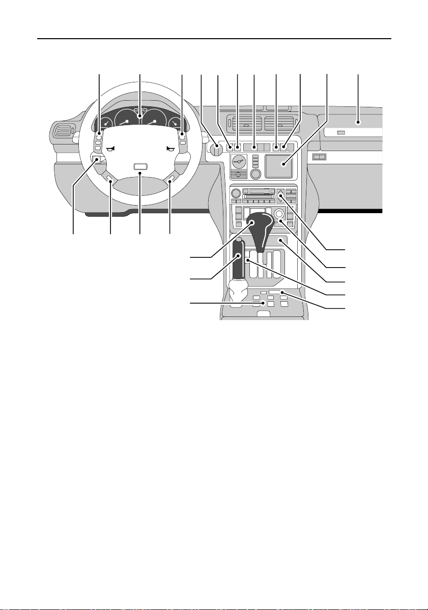
1. Passenger airbag SRS
2. Satellite navigation system
3. Cruise control master switch
4. Hazard warning switch
5. Air suspension switches
6. Rear fog guard light switch
7. Front fog light switch
8. Lighting switch
9. Remote radio/cassette/CDplayerswitches
10.Instrument panel
11.Radio/cassette/CDplayer
CONTROLS
12.Heater/air-conditioningcontrols
13.Ashtray/cigarlighter
14.Automatic gearbox mode switch
15.Exterior mirror operating switches
16.Window and sunroof operating switches
17.Parking brake
18.Automatic gear selector
19.Steering column adjustment lever
20.Cruise control switches
21.Driver’sairbag SRS
234567899
1
11
12
13
14
15
NOTE: The precise specification and location of the controls may vary accordingto territorial
requirements and from model to model within the vehicle range.
2
Page 5
Quick Guide
1 42 3
H4026
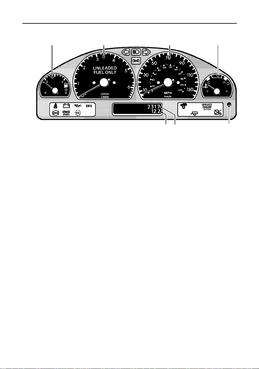
INSTRUMENT PACK
1. Fuel gauge
The pointer drops to zero when the starter
switch is turned off, but quickly rises to show
the level of fuel in the tank when the switch is
turned to position ’II’.
2. Tachometer
Indicates engine speed in revolutions per
minute (x1000).
3. Speedometer
Indicates road speed in miles and/or
kilometres per hour.
67
4. Temperature gauge
Under normal operating conditions, the
pointer should be almost vertical.
5. Trip recorder reset button
6. Total distance recorder (odometer) and
trip recorder
7. Trip recorder (trip 1)
Records individual journey distances.
5
NOTE: This is a brief overview of the instrument panel. For a more detailed description of each
instrument, please refer to the ’Instruments’ section later in this handbook.
3
Page 6
Quick Guide
H4027
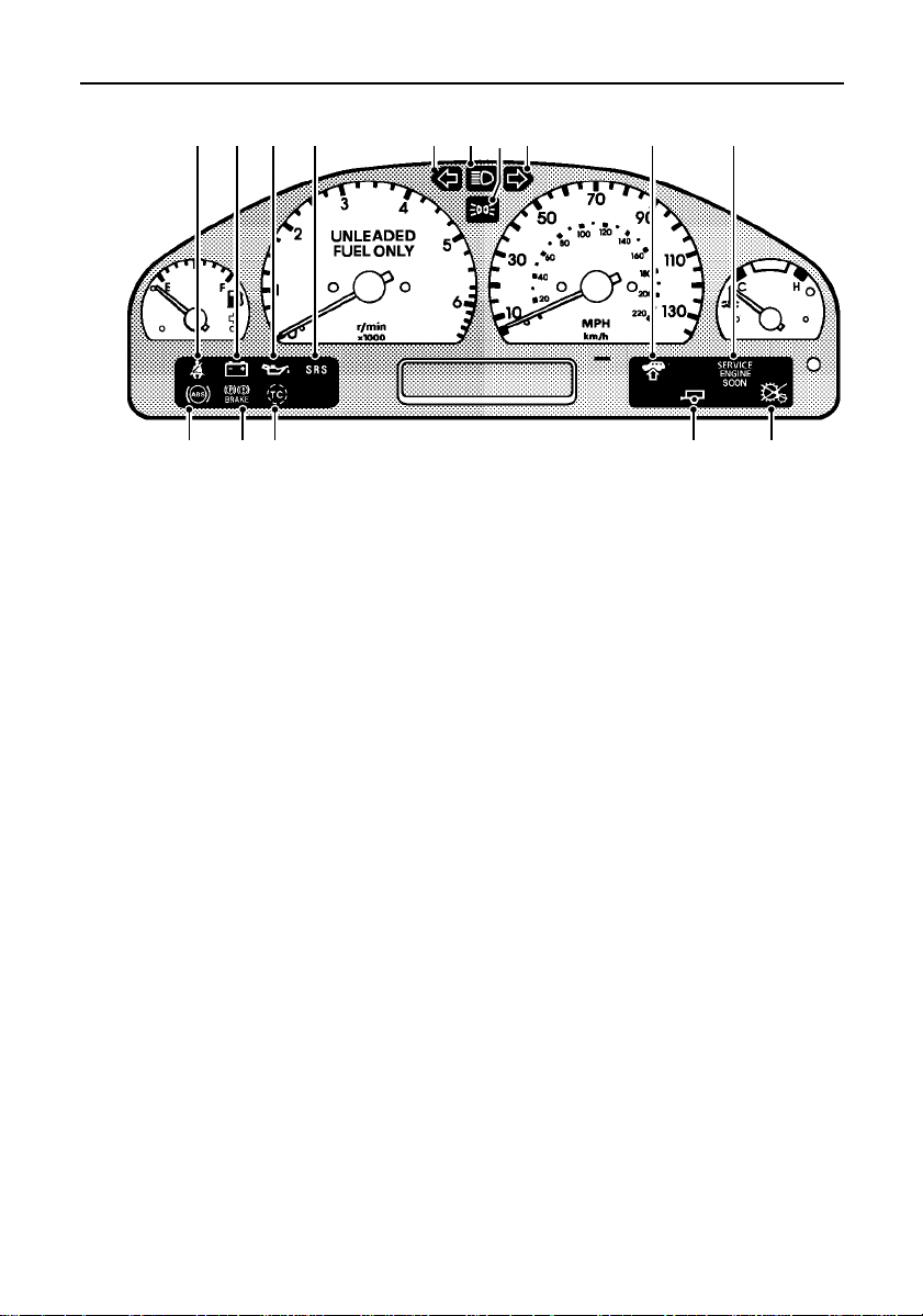
WARNING LIGHTS
1. Seat belt reminder (RED)
2. Battery charging (RED)
3. Low engine oil pressure (RED)
4. Supplementary Restraint System airbags
(RED)
5. Direction indicator (GREEN)
6. Headlight high beam (BLUE)
7. Lights on (GREEN)
8. Direction indicator (GREEN)
5 678
9. Air suspension (AMBER)
10.Service Engine Soon (AMBER)
11.Transfer gearbox (AMBER)
12.Trailer direction indicators (GREEN)
13.Traction control (AMBER)
14.Parking brake/brake system (RED)
15.ABS (AMBER)
91 2 3 4 10
1112131415
NOTE: This is a brief overview of the warning lights, for more information concerning warning
light functionality, please refer to the ’Warning Lights’ section later in this handbook.
4
Page 7
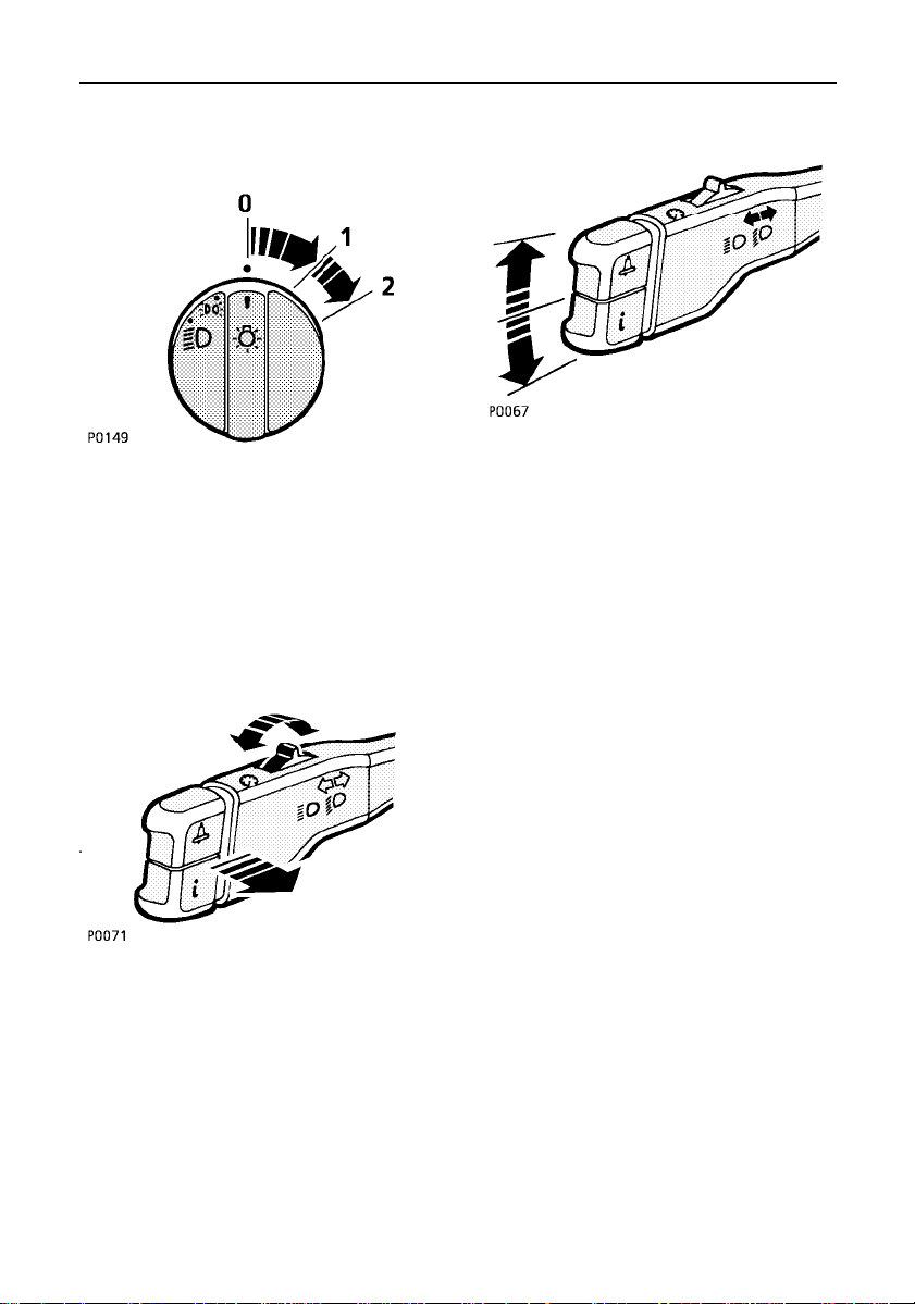
LIGHTS & INDICATORS
Quick Guide
Side, tail and instrument panel lights
Insert the starter key and turn the lighting
switch to position 1.
Headlights
Turn lighting switch to position 2.
Daylight running lights*
The headlights illuminate automatically, when
the starter switch is turned to position II’.
Headlight high and dipped beams
Pull the lever fully towards the steering wheel
to change headlight beams.
Instrument dimmer
Rotate the rocker switch to left or right to
reduce or increase instrument panel
illumination.
Direction indicators
Move the lever DOWN to indicatea LEFT turn,
and UP to indicate a RIGHT turn.
NOTE: For further information concerning
operation of the lights, please refer to ’Lights
& Indicators’ section later in this handbook.
5
Page 8
Quick Guide
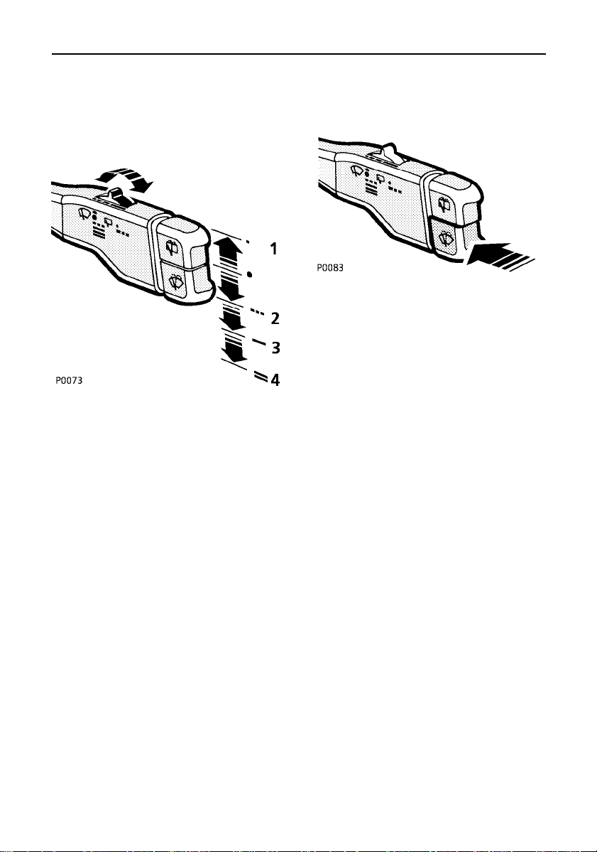
WIPERS & WASHERS
The wipers and washers will only operate
when the starter switch is turned to position
’I’ or ’II’.
Windscreen washers
Press and hold the lower button to operate the
front screen wash/wipe.
Single wipe
Raise the lever to position 1 and release.
Intermittent wipe
Lower the lever to position 2. Rotate
thumbwheel to reduce or increase the delay
between wipes.
Normal speed wipe
Lower the lever to position 3.
Fast speed wipe
Lower the lever to position 4.
Headlight washers*
When the headlights are illuminated, the
headlight washers operate automatically in
conjunction with every second operation of
the windscreen washers.
NOTE: For further information concerning
operation of the wipers and washers, please
refer to ’Wipers & Washers’ section later in
this handbook.
6
Page 9
Quick Guide
1 2 3 4 5 6 7
H4028
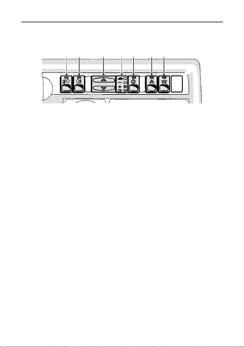
DASHBOARD CENTRE CONSOLE SWITCHES
The following switches are located on the
centre console between the driver and front
seat passenger.
1. Front fog lights
2. Rear fog guard lights
3. Air suspension ride height selector
4. Air suspension ride height indicator
5. Air suspension inhibit switch
6. Hazard warning lights
7. Cruise control
NOTE: For further information concerning
operation of switches, please refer to the
relevant sections of this handbook.
7
Page 10
Quick Guide
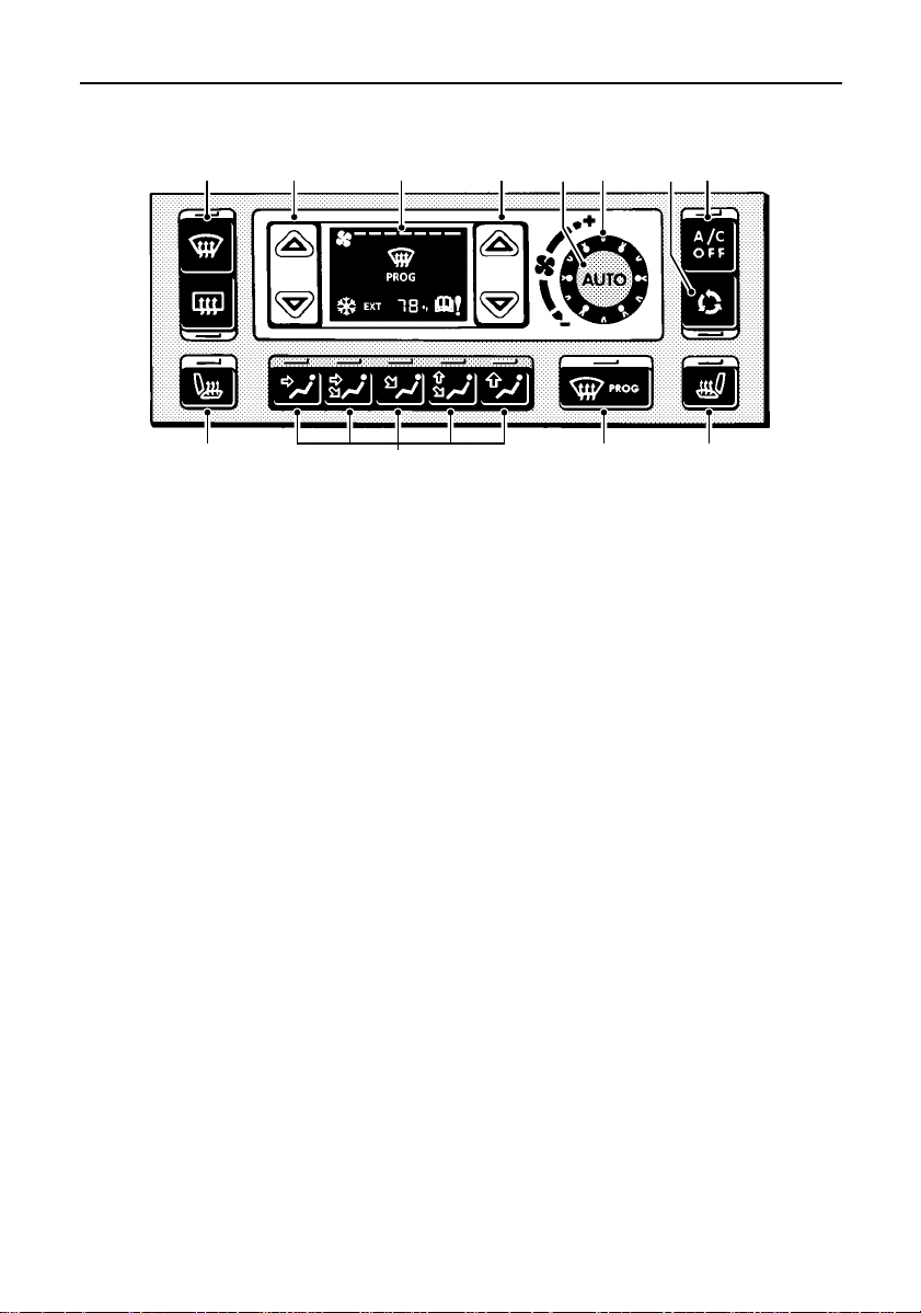
1 2 3 2 5 6
H4029
1. Front and rear screen heaters
As well as being activated by Programmed
Defrost, both front and rear screen heaters
can be operated individually by pressing the
appropriate button.
2. Temperature control
Operate to set the individual left and right
hand desired temperature.
3. Display screen
4. Fan speed control
Turn clockwise to increase and anti-clockwise
to decrease airflow from the vents.
5. Auto mode
Press for fully automatic operation.
8
10
CLIMATE CONTROL
4
7
89
6. Air recirculation
Press to prohibit entry of air from outside the
vehicle.
7. A/C off
Press to switch on or off - when switching on,
the last used settings will be recalled.
8. Heated front seats
9. Defrost mode
Press to defrost or demist the windscreen the blower will be set to maximum, the
distribution control will be set to screen only
and the rear and front screen heaters will be
activated.
10.Air distribution controls
Press the appropriate button to direct air ar
required (the corresponding indicator light
above the switch illuminates).
NOTE: This is a brief overview of the Heating and Ventilation. For a more detailed description,
please refer to ’Heating & Ventilation’ section of this handbook.
8
Page 11
Quick Guide
1 2 3 4 5 7
14
15
H4025
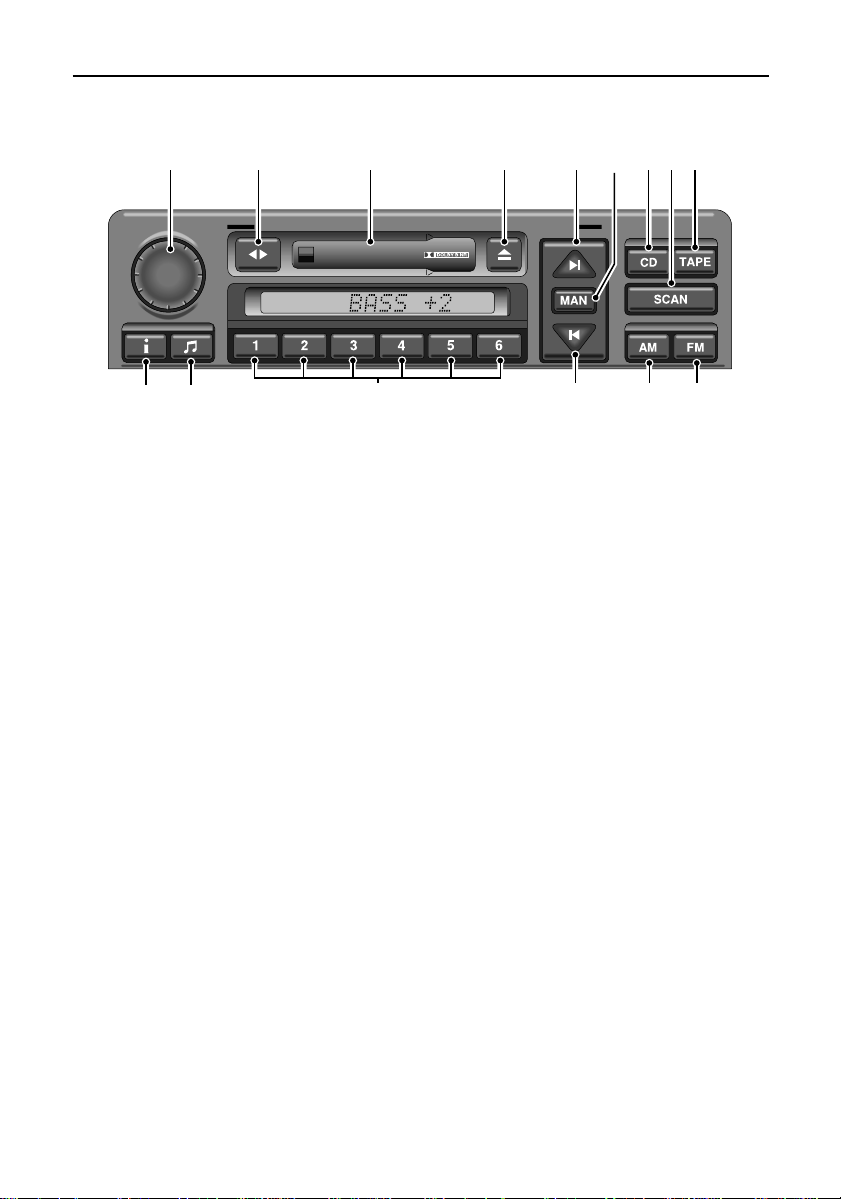
AUDIO SYSTEM CONTROLS
1. On/off and volume control.
Press to switch on or off, rotate to adjust the
volume, or to adjust tone settings.
2. Tape reverse.
Press to play the opposite side of the tape.
3. Cassette compartment.
Insert cassette here with open side to the
right.
4. Cassette eject button.
Press to eject the tape.
5. Tuning button and tape fast forward
control.
6. Manual tuning selector.
Press to select manual tuning mode. Press
again to return to automatic tuning.
7. CD mode selector.
986
111213 10
8. Scan mode button.
Press the button to listen to the first 10
seconds of every track of the selected CD, or
to scan for radio stations.
9. Tape mode selector.
10.FM waveband selector.
Press briefly to select FM frequencies. There
are 2 FM bands, FM1 and FM2.
11.AM waveband selector.
Press briefly to select one of 3 AM bands.
12.Tuning button and tape rewind button.
13.Radio preset buttons .
Use to store up to 6 radio stations on each
waveband.
14.Audio selection button.
Use repeated presses to select bass, treble,
balance, fader and on some models,
subwoofer and digital sound.
15.Traffic and news information.
NOTE: This is a brief overview of the audio system, for a more detailed description, please refer to
your In-Car Entertainment book.
9
Page 12

10
Page 13

SECTION 1
Introduction
In this section of the handbook you will find
information on safety and descriptions of
warning labels located on your vehicle.
For your own safety, it is most important to
read this section fully and to gain a thorough
understanding of all information and warnings
before driving.
Section Contents Page
Passport to service 13....................................
Reporting safety defects 13............................
Safety warnings 14.........................................
Engine compartment labels 15.......................
Vehicle identification number 16.....................
Rollover warning label 17...............................
SRS/Airbag warning labels 17........................
Anti-theft precautions 19................................
Breakdown safety code 19..............................
Land Rover operates a policy of
constant product improvement and,
therefore, reserves the right to change
specifications without notice at any
time. Whilst every effort is made to
ensure complete accuracy of the
information in this handbook, no
liabilities for inaccuracies or the
consequences thereof can be accepted
by the manufacturer or Land Rover
North America Inc.
All rights reserved. No part of this
publication may be reproduced, stored
in a retrieval system or transmitted, in
any form, electronic, mechanical,
photocopying, recording, or other
means without prior written permission
from Land Rover.
11
Page 14

12
Page 15

Introduction
PASSPORT TO SERVICE
Your new Range Rover is covered by the
following warranties:
• Land Rover New Vehicle Limited Warranty
• Land Rover Corrosion Perforation Limited
Warranty
• Land Rover Vehicle Emission Control
System Warranty (U.S.A.)
• Land Rover U.S. Emissions Performance
Warranty
Detailed information on these warranties can
be found in the Passport to Service included
in your literature pack. The Passport to
Service also contains important vehicle
identification information and useful
consumer advice.
Most important of all, however, is the section
on maintenance. This outlines the servicing
requirements for your Range Rover and also
incorporates the service record slips, which
the retailer should sign and stamp to certify
that routine services have been carried out at
the recommended intervals.
REPORTING SAFETY DEFECTS
If you believe that your vehicle has a
defect which could cause a crash or
could cause injury or death, you should
immediately inform the National Highway
Traffic Safety Administration (NHTSA) in
addition to notifying Land Rover North
America Inc.
If NHTSA receives similar complaints, it
may open an investigation and if it finds
that a safety defect exists in a group of
vehicles, it may order a recall and remedy
campaign.
However, NHTSA cannot become
involved in individual problems between
you, your retailer or Land Rover North
America.
To contact NHTSA, you may call the Auto
Safety HOTLINE toll free at
1-800-424-9393 (or 202-366-0123 in the
Washington, D.C. area) or write to
NHTSA, U.S. Department of
Transportation, Washington, DC 20590.
You can also obtain other information
about motor vehicle safety from the
HOTLINE.
13
Page 16

Introduction
SAFETY WARNINGS
WARNING
Safety warnings are included in this
handbook. These indicate a procedure which
must be followed precisely care in order to
avoid the possibility of personal injury or
serious damage to the vehicle.
WARNING
Your Range Rover has a higher ground
clearance and hence a higher centre of
gravity than ordinary passenger cars, to
enable the vehicle to perform in a wide
variety of off-road applications. An
advantage of the higher ground clearance is
a better view of the road allowing you to
anticipate problems. The Range Rover is not
designed for cornering at the same speed as
conventional passenger cars any more than
a low slung sports car is designed to
perform satisfactorily under off-road
conditions. If at all possible, avoid sharp
turns or abrupt manoeuvres. As with other
vehicles of this type, failure to operate the
Range Rover correctly may result in loss of
control or vehicle roll-over. For important
safety information, be sure to read the
"on-road" and "off-road" driving guidelines
given later in this handbook.
CALIFORNIA PROPOSITION 65 WARNING
WARNING
Engine exhaust, some of its constituents and
certain vehicle components contain or emit
chemicals known to the State of California to
cause cancer and birth defects or other
reproductive harm.
14
Page 17
Introduction
WARNING LABELS ATTACHED TO THE
VEHICLE
Warning labels attached to your
vehicle bearing this symbol
mean: DO NOT touch or adjust
components until you have read the relevant
instructions in the handbook.
Warning labels showing this
symbol indicate that the ignition
system utilises very high
voltages. DO NOT touch any ignition
components whilst the starter switch is
turned on!
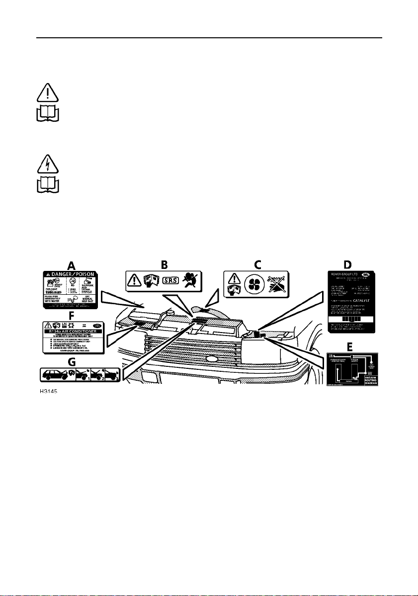
INFORMATION LABELS ENGINE
COMPARTMENT
Various labels are fixed to your vehicleto
draw your attention to specific safety and
emission information. This illustration is for
general guidance only, as the position of the
components and the extent of labels and other
visual warnings could vary from model to
model.
A. BATTERY WARNING LABEL
B. AIRBAG SRS WARNING LABEL
C. KEEP CLEAR OF ROTATING PARTS
D. EMISSION CONTROL LABEL
E. VACUUM ROUTING DIAGRAM
F. AIR CONDITIONING LABEL
G. HOOD CLOSING INSTRUCTIONS
15
Page 18
Introduction
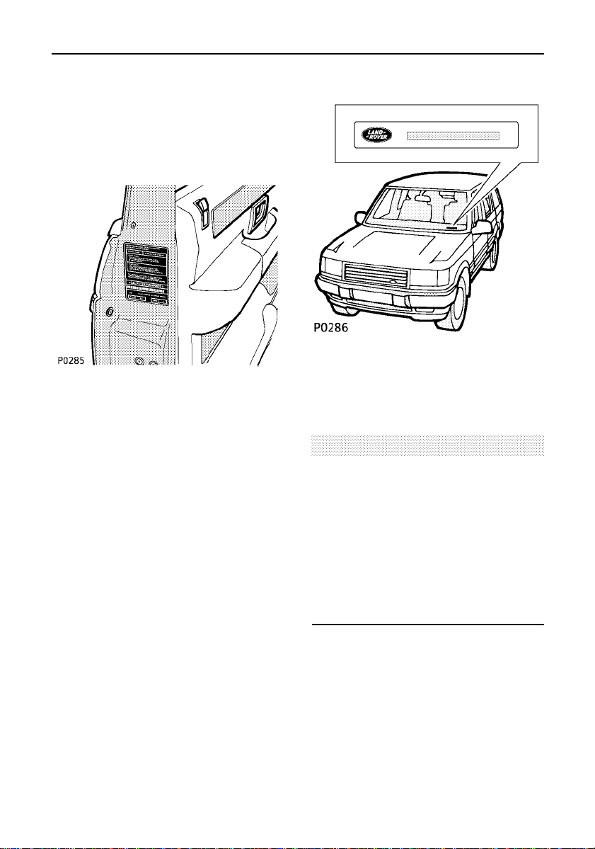
VEHICLE IDENTIFICATION
If you need to communicate with a Land
Rover retailer, you may be asked to quote the
Vehicle Identification Number (VIN).
The VIN and other information concerning
your vehicle can be found on the certification
label affixed to the lock face of the front
left-hand door, where shown.
In addition, the Federal VIN plate is mounted
to the vehicle body in such a position that it is
visible from the outside through the bottom
corner of the windscreen on the driver’s side.
WARNING
DO NOT exceed gross weight or axle loads
described on the vehicle certification
identification label. Exceeding allowable
vehicle and axle loads will increase the risk
of tyre and suspension failure, increase
vehicle brake stopping distance and
adversely affect vehicle handling and
stability which may result in a crash or
rollover.
16
Page 19
WARNING:
!
HIGHER RISK OF ROLLOVER
Avoid Abrupt Maneuvers
and Excessive Speed.
Always Buckle Up.
See Owner's Manual
For Further Information
Introduction
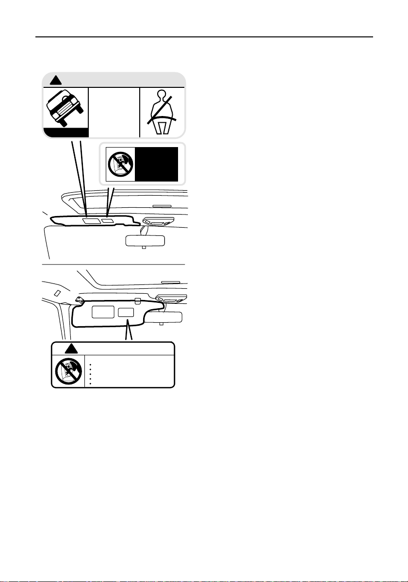
ROLL-OVER WARNING LABEL
Take note of the warning label on the
sunvisor, which alerts the driver to the need to
be aware of the higher roll-over risk,
associated with utility vehicles of this type
(see also the relevant warning earlier in this
section).
H3146
!
WARNING
DEATH or SERIOUS INJURY can occur
Children 12 and under can be killed by the airbag
The BACK SEAT is the SAFEST place for children
NEVER put a rear-facing child seat in the front
Sit as far back as possible from the air bag
ALWAYS use SEAT BELTS and CHILD RESTRAINTS
AIR BAG
WARNING
FLIP VISOR OVER
SRS/AIRBAG WARNING LABELS
SRS/Front airbag systems
Take note of the warning information fixed to
the underside of both sun visors, as follows:
WARNING!
DEATH or SERIOUS INJURY can occur
• Children 12 and under can be killed by the
airbag
• The BACK SEAT is the SAFEST place for
children
• NEVER put a rear-facing child seat in the
front
• Sit as far back as possible from the airbag
• ALWAYS use SEAT BELTS and CHILD
RESTRAINTS
17
Page 20
P0418
Introduction
WARNING
ATTENTION
let a child`s head rest near side
NEVER
airbag. Inflating airbag can cause
serious or fatal injury.
use safety belts and child
ALWAYS
See owners manual.
restraints.
NE LAISSEZ JAMAISun enfant
reposer sa tete pres d'un airbag
lateral en se gonflant. L'airbag
pourrait occasionner des blessures
graves voire fatales.
Utilisez
les ceintures de
TOURJOURS
securite et systemes de retenue pour
enfants.Voir Notice d’Utilisation
The use of seat covers that
are not approved for front
seats with side air bags will
reduce the effectiveness of
the side airbag in a crash
La pose de housses non
approuvees pour utilisation sur
sieges avant equipes de
coussins gonflables latcraux
reduit l'efficacite des coussins
gonflables lateraux en cas de
collision
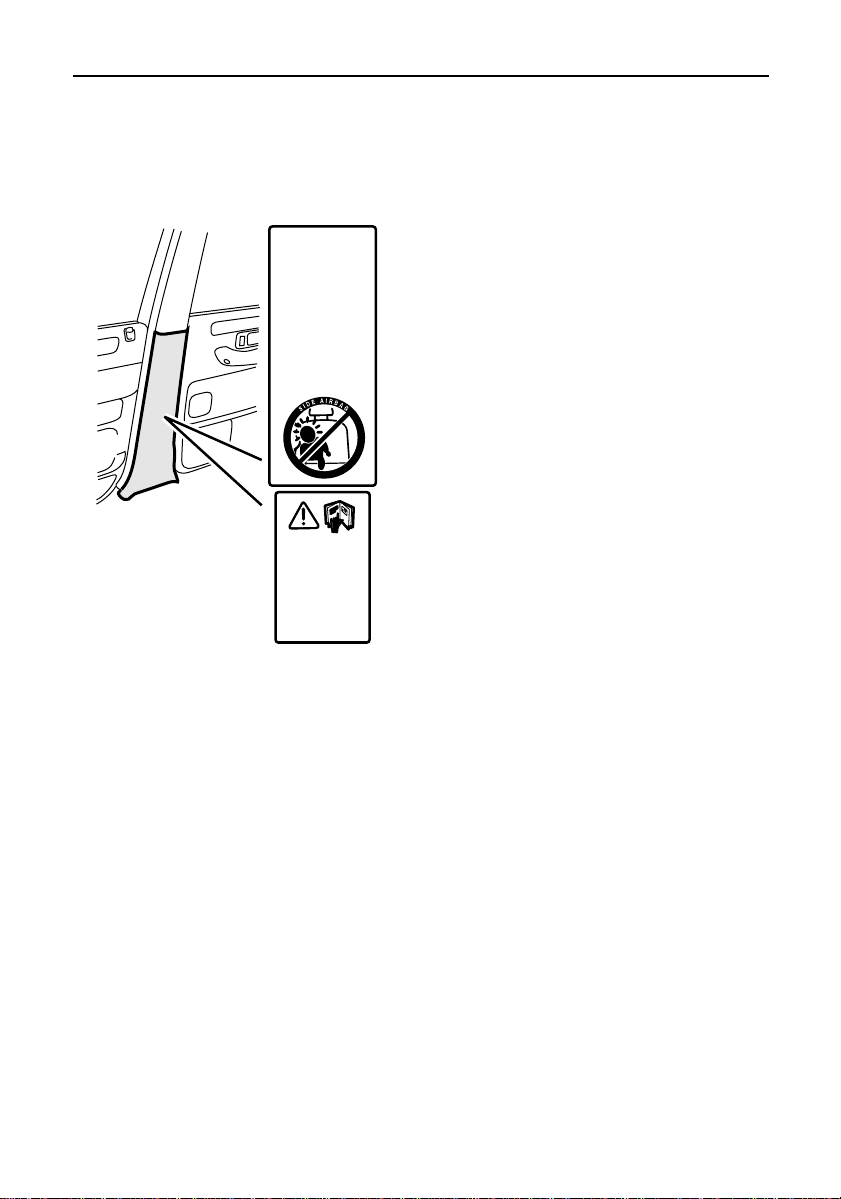
SRS/Side airbag systems
Take note of the warning information fixed to
B/C posts, as follows:
WARNING
NEVER let a child’s head rest near a side
airbag. Inflating airbag can cause serious or
fatal injury.
ALWAYS use safety belts and child
restraints. See Owner’s Manual.
The use of seat covers that are not approved
for front side airbags will REDUCE the
effectiveness of those airbags in a crash.
18
Page 21

Introduction
ANTI-THEFT PRECAUTIONS
whilst it may be difficult to deter the
’professional’car thief, the majority of thefts
are carried out by unskilled opportunists.
Therefore, take vehicle security very seriously
and ALWAYS adopt this simple ’four point’
drill whenever you leave your vehicle - even
for just a few minutes:
1. Fully close all the windows (and the
sunroof).
2. Remove your valuable belongings (or hide
them out of sight).
3. Remove the starter key.
4. Superlock the vehicle using the remote
handset.
Thieves are attracted by ’vulnerable’ vehicles.
Even if you have followed the ’four point’ drill,
there is still much you can do to make your
vehicle a less inviting target.
BE SAFE - NOT SORRY!
• Park where your vehicle can be easilyseen
by householders and passers-by.
• At night, park in well lit areas and avoid
deserted or dimly-lit side streets.
• NEVER leave the keys in the vehicle.
• Do not keep important documents (or
spare keys) in the vehicle - these are a real
bonus for the thief.
IMPORTANT INFORMATION
Remember the breakdown
safety code
If a breakdown occurs whilst travelling:-
• Wherever possible, consistent with
safety and traffic conditions, the
vehicle should be moved off the
main thoroughfare, preferably onto
the shoulder as far as possible. If a
breakdown occurs on a freeway, pull
well over to the inside of the hard
shoulder.
• Switch on hazard lights.
• If possible, position the warning
triangle (located on the underside of
the loadspace floor panel - see
’Warning triangle’) or a flashing
amber light at an appropriate
distance from the vehicle to warn
other traffic of the breakdown (note
the legal requirements of some
areas).
• Consider evacuating passengers
through the doors facing away from
the traffic, to a safe area away from
the vehicle as a precaution in case
your Range Rover is struck by
another vehicle.
19
Page 22

20
Page 23

SECTION 2
Controls & instruments
In this section of the handbook you will find
descriptions of the controls and instruments
on your vehicle.
For your own safety, it is most important to
read this section fully and to gain a thorough
understanding of all the controls before
driving.
Section Contents Page
Security card 23.............................................
Locks & alarm 24...........................................
Tailgate 32......................................................
Message centre 33.........................................
Seats 42.........................................................
Seat belts 50...................................................
SRS/Airbag 58................................................
Steering column 65........................................
Door mirrors 66..............................................
Instruments 68...............................................
Warning lights 70...........................................
Lights & indicators 74....................................
Wipers & washers 76.....................................
Switches 79....................................................
Electric windows 81........................................
Electric sunroof 84.........................................
Heating & ventilating 87.................................
Interior equipment 91.....................................
In-car telephones 96.......................................
21
Page 24

22
Page 25

Security Card
The security card, supplied with the literature
pack, contains important emergency
information. It is ESSENTIAL that you keep
the card safe from theft and ensure that it is
passed to the new owner if you sell the
vehicle.
• Key number: This is the number of the
starter/door key - essential if you ever
need to obtain a replacement.
• VIN (vehicle identification number): This
identity number is unique to your vehicle
and is essential proof of its specification.
The number can also be found in various
locations around the vehicle (see ’Vehicle
Identification’ in Section 1).
• Radio security code number: Your vehicle
is delivered with the security code
disabled. If you wish to have it actuated
see your Land Rover retailer.
CAUTION
Never leave the security card inside the
vehicle when it is unattended.
23
Page 26
Locks & alarm
Your vehicle is fitted with a sophisticated
electronic anti-theft alarm system. In order to
ensure maximum security, you are advised to
gain a full understanding of the system by
thoroughly reading this section of the
handbook.
LOCKING THE VEHICLE AND ARMING THE
ALARM
You have been supplied with two
handset/keys (numbered 1 and 2). Whilst both
are identical in operation, they transmit two
different sets of information (see ’Key
activated memory seats’). Replacement
handsets are only available from a Land Rover
retailer. Up to two further handsets (3 and 4)
can also be obtained.
There are four methods for securing your
vehicle:
1. ’Superlocking’using the handset -
(recommended high security method).
2. ’Superlocking’using the key.
3. Locking using the handset.
4. Locking using the key.
FOR MAXIMUM SECURITY, ALWAYS
’SUPERLOCK’ THE VEHICLE USING THE
HANDSET
(except when the vehicle is to be locked with
passengers or animals inside).
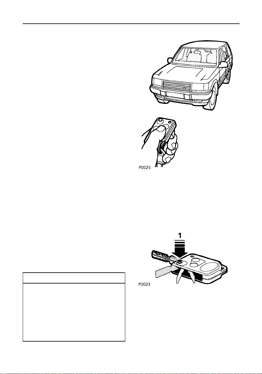
The handset
The radio remote handset has three buttons
(described below). By pressing the
appropriate button, the handset can be used
either as a conventional key, or as a remote
handset to either lock or ’superlock’the
vehicle.
IMPORTANT INFORMATION
Emergency keys
In addition to the two handsets, you have
also been supplied with two separate
keys. These keys perform the same
functions as the key part of the handset
and are intended for emergency use only.
DO NOT keep the keys inside the vehicle.
1. Key release button.
• Press to release the key, which can then
be used as a conventionalkey to operate
the starter switch, glovebox and door
locks.
24
Page 27
Locks & alarm
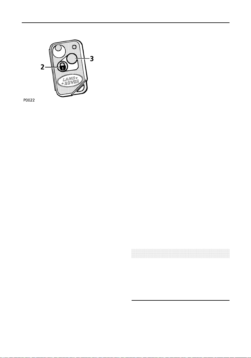
2. Lock button (padlock symbol)
• press once to lock.
• press twice to ’superlock’.
3. Unlock button
• press once to unlock.
• press and hold to operate the ’Key
activated memory seats’ facility (see ’Key
activated memory seats’).
Once the security system is armed, the
following features are activated:
• The central locking system locks all the
doors and the tailgate.
• The perimetric alarm (protecting the
doors, hood and tailgate) is armed.
• If ’handset superlocking’ is activated, the
volumetric alarm is also armed (a sensor
inside the passenger compartment
monitors the interior space and activates
the alarm if an intrusion into the
passenger compartment is detected).
The volumetric sensor will enter a self-check
mode each time you turn the starter switch
off. It will remain active for 60 seconds, or
until:
1. The driver’s door is opened and closed.
2. The vehicle is locked with the handset or
key.
NOTE: If the sensor fails its self-check five
times consecutively, only the ’perimetric’
elements of the security system will be active
(doors, hood and tailgate). Any attempt to
’superlock’with the handset will result in
’ALARM FAULT’ being displayed on the
message centre and a mislock occurring (see
’Mislock’).Seek qualified assistanceto rectify
the fault.
NOTE: The handset complies with part 15 of
the FCC Rules. Operation is subject to the
following two conditions:
1. This device may not cause harmful
interference.
2. This device must accept any interference
received, including interferencethat may
cause undesired operation. This applies to
both alarm receivers and handset
transmitter.
CAUTION
Any changes or modifications to the
transmitter not expressly approved by the
manufacturer or Land Rover North America
could void the user’s authority to operate the
equipment.
25
Page 28
Locks & alarm
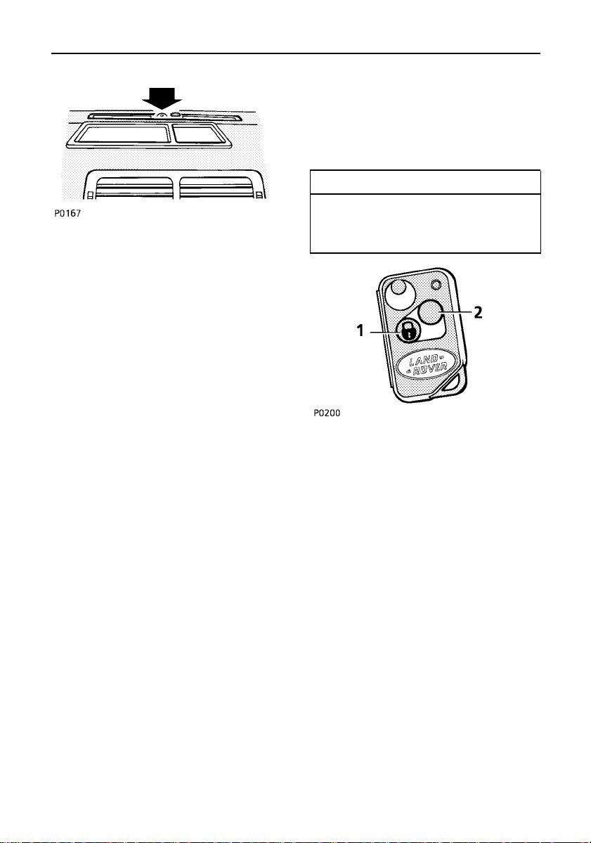
Anti-theft alarm indicator light
After locking the vehicle, the RED indicator
light on the top of the fascia, close to the
windscreen (arrowed in illustration) flashes
rapidly for ten seconds to confirm that the
security system has been successfully armed.
After ten seconds, the indicator light adjusts
to a slower frequency, and then continues to
flash as an anti-theft deterrent until such time
as the security system is disarmed.
If, whilst operating the handset (or key), the
alarm sounds, this indicates that one of the
doors, the hood or the tailgate is not properly
closed (the message centre display will
confirm which aperture is not secure).
Although the handset can be successfully
operated from a significant distance from the
vehicle, when locking it is wise to be close
enough to visually confirm that the door
locking buttons have dropped into place and
that the indicator light confirms a successful
lock.
NOTE: Occasional atmospheric conditions
can significantly reduce the effective range of
handset operation. If this occurs, operate the
handset closer to the vehicle. In the most
extreme cases, it may be necessary to touch
the handset against the radio aerial’fired’onto
one of the rear side windows.
If the message centre displays ’KEY BATTERY
LOW’, this indicates that the handset batteries
need replacing (see ’Handset batteries’).
SUPERLOCKING
If the vehicle is ’superlocked’ (with either the
handset, or the key), the doors CANNOT be
unlocked or opened from inside the vehicle.
IMPORTANT INFORMATION
For the reason given above, DO NOT
superlock the vehicle with passengers
inside.
’Superlocking’ using the handset:
Press and release the ’lock’ button (1) on the
handset twice (within 1
seconds you will hear ’superlocking’ engage.
If any door, the hood or tailgate is left open, a
mislock will occur (see ’Mislock’).
If a window or sunroof is open, superlocking
will engage immediately, however volumetric
protection will not be activated.
To unlock:
Press and release the ’unlock’ button (2) on
the handset once.
If the handset is inoperative,the vehicle can
be unlocked by using the key in the driver’s
door lock.
1
/2seconds). After 15
26
Page 29

Locks & alarm
’Superlocking’ using the key:
Wherever possible the handset MUST be used
to ’superlock’ the vehicle. However, if the
handset is inoperative, the key can be used as
follows:
Turn the key in the driver’s door towards the
rear of the vehicle (and release) twice within
1
1
/2seconds.
NOTE: ’Superlocking’ the vehicle using the
key will provide perimetric protection only volumetric protection (protection of the
interior space inside the vehicle) WILL NOT
BE ACTIVE! If any door, the hood, or the
tailgate is left open, a mislock will occur (see
’Mislock’).
To unlock:
Wherever possible use the handset to unlock
the vehicle - press and release the ’unlock’
button.
If necessary, the key can also be used to
unlock a ’superlocked’ vehicle.
IMPORTANT INFORMATION
If unattended passengers are to be left in
the vehicle, it is recommended that they
should lock the vehicle from inside by
pressing down the driver’s door sill
button.
If animals are to be left in the vehicle,
volumetric protection MUST NOT be
activated - any movement inside the
vehicle could trigger the alarm.
NEVER leave children or animals
unattended in the vehicle!
WARNING
NEVER ’superlock’ the vehicle if passengers
are to be left inside - ’superlocking’
prevents door locks from being operated
from INSIDE as well as outside the vehicle!
NOTE: If the handset ’lock’ button or the door
key are operated once, the central locking will
be activated, but the alarm will only be in
’perimetric’mode and the doors and locks
CAN be opened from the inside. ALWAYS,
where possible secure the vehicle by
’superlocking’.
’Sill’ locking
To operate the central locking from inside the
vehicle, push down either front door sill
button.
The security system will NOT be armed.
NOTE: ’Sill’ locking is NOT possible from
outside the vehicle.
27
Page 30

Locks & alarm
MISLOCK
A mislock will occur if:
• A door, hood or tailgate are left open.
• The key is left in the starter switch.
• An incomplete ’all close’ is attempted. The
message centre will indicate the cause of a
mislock e.g. ’SUNROOF BLOCKED’.
If a mislock occurs, a warning ’bleep’ will
sound in which case you should unlock the
vehicle, rectify the cause of the mislockand
then re-lock the vehicle.
’ALL CLOSE’ FEATURE
The key activated ’all close’ feature enables
you to use the key to close the windows and
sunroof at the same time as you secure the
vehicle.
To operate:
1. Ensure the doors, hood and tailgate are
properly closed.
2. Turn and hold the key in the ’lock’ position
(turn twice and hold on the second turn if
’Superlocking’).
The doors and tailgate will lock and the
windows, followed by the sunroof will close.
NOTE: If a window or the sunroof detects an
obstruction, a mislock occurs and the locking
sequence will stop. Remove the obstruction
before trying to use the ’all close’ feature
again.
KEY ACTIVATED MEMORY SEATS
This feature enables the handsets to be used
to recall the pre-set electric seat/mirror
positions when you UNLOCK the door. The
two handsets are separately identified by
different labels and by grey and black battery
covers - key 1 corresponds to driver’sseat
memory 1, and key 2 to seat memory 2 (see
’Seats’).
NOTE: If additionalhandset/keyshave been
obtained (key 3 & key 4), they are not linked
to the memory seat system.
Press and hold the ’unlock’button on the
handset for 1
on the handset flashes rapidly), and then
release. The driver’s seat and both mirrors will
move to the positions programmed into the
relevant seat memory.
1
/2seconds (the indicator light
NOTE: This feature will only operate if
volumetric protection was activated when the
vehicle was locked (ie. by ’superlocking’ using
the handset).
It will not function if the alarm system has
already been triggered since it was last set,
and will be cancelled if a door is opened, or if
the vehicle is relocked.
28
Page 31

Locks & alarm
AUTO RELOCK
Auto relock ensures that, if the vehicle is
unlocked accidentally,the vehicle will relock
itself automatically after a 60 second delay.
Once the ’unlock’ button on the handset has
been pressed, the alarm system will monitor
the vehicle for 60 seconds. If any of the
following occur during this period, the vehicle
will remain unlocked:
• A door or the tailgate is opened.
• Interior movement is detected.
• The key is inserted into the starter switch,
or the switch is turned to position ’I’.
However, if none of the above has occurred
within 60 seconds, then the vehicle will
automaticallyreturn to its previous ’locked’
state.
OPENING THE DOORS
When opening a door from outside the
vehicle, it is recommended that the moving
part of the handle is held by the fingers and
that the door catch is operated by pushing
with the thumb against the fixed part of the
handle.
CHILD-PROOF LOCKS (rear doors only)
Move the lever downwards (arrowed in
illustration)to engage.
With the child-proof locks engaged, the rear
doors cannot be opened from inside the
vehicle, thereby avoiding the risk of a door
being opened accidentally whilst the vehicle is
moving.
WARNING
TO AVOID INJURY OR DEATH, NEVER LEAVE
CHILDREN UNSUPERVISED IN THE VEHICLE.
29
Page 32

Locks & alarm
INERTIA CUT-OFF SWITCH
This switch is a safety devicethat
automaticallyunlocks the doors in the event
of an accident or sudden impact (provided the
starter switch is turned on). In addition, the
inertia switch inhibits power to the electric
fuel pump, turns off the heating and air
conditioning fans, and turns on the hazard
warning lights, which continue flashing until
either the starter switch is turned off or the
inertia switch is reset.
The switch is located behind the vertical panel
in the right hand footwell. Remove the cover
by using a coin to rotate the turnbuckle
anti-clockwiseand then prise the cover off.
When the switch is tripped, the message
centre will alternately display; ’REFER
HANDBOOK’ and ’INERTIA SWITCH’.
To reset the switch, press the rubber top
(arrowed in illustration).
NOTE: The vehicle can be secured even if the
switch has been tripped by removing the
starter key, opening and closing one of the
front doors and then locking the vehicle.
WARNING
Always check for fuel leaks before resetting
the switch! Activating the switch when the
fuel system has been damaged (evidenced
by fuel leakage) will cause additional fuel
leakage, increasing the risk of fire or
personal injury.
30
Page 33

Locks & alarm
Handset batteries
When the batteries need replacing, the
message centre will display ’KEY BATTERY
LOW’. To replace:
• Remove the battery cover by turning the
cover anti-clockwisewith a coin.
• Taking care not to touch the circuit board,
prise the batteries from the cover and fit
new ones (with the positiveside facing the
cover), and replace the cover.
The batteries should be replaced within 1
minute of removing the old ones, otherwise it
may be necessary to re-synchronise the
handset (see ’Handset synchronisation’). New
batteries are available from your retailer.
Handset synchronisation
The handset transmits a coded message,
which changes each time a button is pressed.
If a handset is operated too many times out of
range of the vehicle or if the handset batteries
are removed for longer than a minute, it may
need to be re-synchronised.
To synchronise:
• If the vehicle is locked, press the ’unlock’
button on the handset and then unlock the
vehicle using the key.
• If the vehicle is unlocked, press the ’lock’
button on the handset and then lock the
vehicle using the key.
NOTE: Handset synchronisation cannot be
achieved if the vehicle alarm is armed or if the
handset batteries need replacing.
NOTE: Finger marks on the batteries will
adverselyaffect battery life. If possible, avoid
touching the surface of the batteries, and wipe
clean before fitting.
31
Page 34

Tailgate
OPENING THE TAILGATE
With the vehicle unlocked, press the release
button once to release the upper tailgate.
NOTE: There is a handle built into the lower
edge of the upper tailgate to assist in opening
and closing.
With the upper tailgate open, press the release
button again to release the lower tailgate,
which can then be lowered to the horizontal
position.
WARNING
Do not drive with the tailgate open;
poisonous carbon monoxide fumes will
enter the vehicle which could cause serious
injury or death.
CLOSING THE TAILGATE
Raise the lower tailgate first and close firmly.
Then lower and close the upper tailgate.
Always check that the tailgate is securebefore
driving and before leaving the vehicle
unattended.
NOTE: The tailgate cannot be opened if the
vehicle battery is flat or disconnected;
emergency access to the loadspace can only
be achieved, by folding the rear seats from
inside the vehicle, (see ’Seats’).
32
Page 35

Message centre
Driver warning and information messages are
displayed on the message centre in the lower
part of the instrument pack. Messages have
different priority levels and are grouped into
the following categories.
CRITICAL WARNINGS
Critical warning messages are accompanied
by an audible warning (three beeps).
Messages are displayed continuously whilst
the starter switch is turned on, and remain
displayed whilst the fault persists.
DO NOT ignore these messages - TAKE
CORRECTIVE ACTION IMMEDIATELY!
Critical warnings are displayed continuously,
normally on the lower line of the message
centre, but if more than one message is to be
displayed, then the upper display line will also
be used.
WARNINGS
Warning messages must be treated with some
urgency. They will also be accompanied by an
audible warning (three beeps) each time the
message is displayed.
DO NOT ignore these messages - TAKE
CORRECTIVE ACTION IMMEDIATELY.
Warning messages are displayed for
approximately4 seconds. If other warning
messages are pending, the display time will be
reduced to approximately 2 seconds.
INFORMATION MESSAGES
General
All information messages are displayed for
approximately4 seconds. If other messages
are pending, the display time will be reduced
to approximately 2 seconds. Note that ’Critical
Warning’ and ’Warning’ messages always
override ’Information’ messages.
These information messages are grouped into
three categories:
Category 1
Messages in this category will be
accompanied by a single beep when the
message is displayed for the first time, and
also when the starter switch is turned on or
off. At any other time, only the message will
be presented - TAKE CORRECTIVE ACTION AS
SOON AS POSSIBLE.
Category 2
Messages in this category will be
accompanied by a single beep each time the
message is displayed - if action is necessary,
take corrective action as soon as possible.
Category 3
Messages in this category are NOT
accompanied by an audible warning. Only the
message will be displayed - TAKE
CORRECTIVE ACTION AS SOON AS
POSSIBLE.
33
Page 36

Message centre
The following are CRITICAL WARNING messages and are listed in order of priority.
Message Meaning Whatto do?
MARKET NOT SET the language for the message centre
is not set
SEAT BELT PLEASE you have not fastened your seat belt fasten your seat belt
INERTIA SWITCH* the fuel cut-off switch has been
tripped
GEARBOX OVRHEAT * automaticgearbox oil temperature
too high
TRANSFER OVRHEAT* transfergearbox oil temperaturetoo
high
DOOR OPEN RH-R the right hand rear door is open close the door
DOOR OPEN LH-R the left hand rear door is open closethe door
DOOR OPEN LH-F the left hand front door is open close the door
DOOR OPEN RH-F the right hand front door is open close the door
BONNET OPEN thehood is open closethehood
IGNITION KEY IN you have left the key in the starter
switch
LIGHTS ON you have left your lights on switchoff the lights
seek qualified assistance
reset the switch - see ’Locks
& alarm’
reduce speed or select
lower gear. If message
persists, stop vehicle and
allow gearbox to cool; seek
qualified assistanceif
message resumes.
reduce speed or select
lower gear. If message
persists, stop vehicle and
allow gearbox to cool; seek
qualified assistanceif
message resumes
remove the key
* These messages alternate with the message’REFER HANDBOOK’.When this is displayed, refer
to the appropriate section in this handbook for further information.
34
Page 37

Message centre
Message Meaning Whatto do?
HEADLIGHT DELAY you have selected headlight delay -
headlights will switch off
automatically
SLOW: 35 MPH MAX air suspension fault slow down to less than 35
mph and seek qualified
assistance
ENG OIL OVERHEAT engine oil temperature is too high stop and allow the engine to
cool; if the problem
persists, do not drive - seek
qualified assistance
AIRBAG FAULT there is a problem with the airbag seekqualified assistance
RH FRONT WINDOW alternates with one of the following: referto the description
LH FRONT WINDOW WINDOW NOT SET, WINDOW given for the alternating
RH REAR WINDOW BLOCKED, ANTI-TRAP OFF, message
LH REAR WINDOW or WINDOW OPEN
SPEED LIMIT--- you have exceeded your preset
speed limit
SPEED LIMIT OFF the preset speed limit has been
cancelled
FUEL GAUGE FAULT as message suggests seek qualified assistance
TEMP GAUGE FAULT as message suggests seek qualified assistance
LH SEAT HEATER the fuse has blown fit a new fuse - this
RH SEAT HEATER as above as above
SUNROOF the ’ANTI-TRAP’ function is
overridden (alternateswith message
ANTI-TRAP OFF)
TRANSFER NEUTRAL the transfer box has moved to the
neutral position
reduce your speed or cancel
the function
message alternates with the
fuse number message
refer to ’ANTI-TRAP OFF’
message
remove fuse 11 if transfer
neutral is no longer required
35
Page 38

Message centre
Message Meaning Whatto do?
BONNET opening the hood was the cause of
the alarm system triggering
LH FRONT DOOR opening this door was the cause of check that the vehicleis
RH FRONT DOOR thealarmsystemtriggering secure - message
LH REAR DOOR alternates with ALARM
RH REAR DOOR TRIGGERED message
IGNITION TAMPER turning the starter switch on was the
cause of the alarm system triggering
TAILGATE opening the tailgate was the cause
of the alarm system triggering
The following are WARNING messages;
Message Meaning Whatto do?
TAILGATE OPEN the tailgate is open close the tailgate
WINDOW BLOCKED the anti-trap function has detected
an obstruction whilst the window is
being closed
SUNROOF BLOCKED theanti-trapfunctionhas detected
an obstruction whilst the sunroof is
being closed
ALARM FAULT the alarm system has a fault seek qualified assistance
ANTI-TRAP OFF the anti-trapfunction for one or
more windows or the sunroof is
disabled - message alternates with
another to indicate which anti-trap
function is disabled
EAS FAULT there is a fault with the air
suspension system
ABS FAULT there is a fault with the anti-lock
braking system
check that the vehicle is
secure - message alternates
with the ALARM
TRIGGERED message
as above
as above
this message will alternate
with another one to indicate
which window is affected remove the obstruction
remove the obstruction
before trying to reclose the
sunroof
ensure that there are no
obstructions in the aperture
seek qualified assistance
seek qualified assistance
36
Page 39

Message centre
Message Meaning Action
SLOW: 20 MPH MAX your road speed is too high for the
current ride height
SLOW: 35 MPH MAX your road speed is too high for the
current ride height
FUSE FAILURE MESSAGES
The following fuse failure messages are INFORMATION CATEGORY 1 messages. (see ’Fuses’ for
fuse replacement information).
Message Meaning Action
FUSE 2 to 22 FAILED Fuse blown Fit a new fuse
Notes:
1. The fault messages for fuses 10 and 20
may also be displayed in conjunction with
the messages ’RH SEAT HEATER’ and ’LH
SEAT HEATER’. This will occur if the seat
heater affected by the relevant blown fuse
is operated.
2. The fault message for fuse 12 may also be
displayed in conjunction with the message
’HEATED REAR WINDOW’. This will occur
if the heated rear screen is operated after
fuse 12 has blown.
3. In all cases, the fuse failed message will
alternate with the appropriate description
message e.g. ’FUSE 10 FAILED’, followed
by ’RH SEAT HEATER’.
4. Fuse 1 covers the instrument pack. If this
fuse fails, replace the fuse (no message
can be given because the messagecentre
is controlled by the instrument pack).
5. The message centre responds to multiple
fuse failures by displaying separate
messages, one after the other.
slow down to less than 20
mph
slow down to less than 35
mph
37
Page 40

Message centre
BULB FAILURE MESSAGES
The following are INFORMATION CATEGORY 1 messages.(see ’Bulb replacement’).
Message Meaning Whatto do?
RH DIP BEAM Bulb failed Replace bulb
LH DIP BEAM Bulb failed Replace bulb
RH MAIN BEAM One or both bulbs failed Replacebulb
LH MAIN BEAM One or both bulbs failed Replacebulb
RH SIDE LIGHT Bulb failed Replacebulb
LH SIDE LIGHT Bulb failed Replacebulb
FRONT INDICATOR One or both bulbs failed Replacebulb
RH FRONT FOG Bulb failed Replacebulb
LH FRONT FOG Bulb failed Replacebulb
RH TAIL LIGHT Bulb failed Replacebulb
LH TAIL LIGHT Bulbfailed Replace bulb
RH BRAKE LIGHT Bulb failed Replace bulb
LH BRAKE LIGHT Bulb failed Replace bulb
REAR INDICATOR Oneor both bulbs failed Replace bulb
RH REAR FOG Bulb failed Replace bulb
LH REAR FOG Bulb failed Replace bulb
RH REVERSE Bulb failed Replace bulb
LH REVERSE Bulbfailed Replace bulb
NUMBER PLATE Bulb failed Replace bulb
The message centre will respond to multiple bulb failures by displaying separate messages, one
after the other.
All bulb failure messages will be displayed when the starter switch is turned on or off and when
the system affected by the relevantbulb failure is operated. The message ’BULB FAILURE’ will
alternate with the appropriate bulb description message, e.g. ’BULB FAILURE’ followed by ’RH
REAR FOG’.
38
Page 41

Message centre
MISCELLANEOUS FAULT MESSAGES
The following are INFORMATION CATEGORY 1 messages.
Message Meaning Whatto do?
LOW SCREEN WASH as message suggests fill the screenwash reservoir
GEARBOX FAULT as message suggests seek qualified assistance
TRACTION FAILURE as message suggests seekqualifiedassistance
LOW BRAKE FLUID as message suggests top-up the fluid reservoir
and/or seek qualified
assistance
ODOMETER ERROR as message suggests seek qualified assistance
KEY BATTERY LOW as message suggests fit new batteries in the
handset
The following are INFORMATION CATEGORY 2 messages.
Message Meaning Whatto do?
MEMORY 1 STORED youhavestoredthe seat and mirror
positions into memory store 1
MEMORY 2 STORED youhavestoredthe seat and mirror
positions into memory store 2
REAR WINDOWS ON the rear window isolation switch has
been operated while the starter
switch was turned off, leaving the
rear window switches operational.
REAR WINDOWS OFF the rear window isolation switch has
been operated while the starter
switch was turned off, leaving the
rear window switches isolated.
WARNING: To avoid injury, ensure that the rear window swiches are isolated when carrying
children.
ALARM TRIGGERED the alarm has been triggered since
the ignition was last turned off
MIRROR DIP STORE youhavestoredthe reverse dip
positions of the door mirrorsin
memory
39
no action required
no action required
take appropriate action to
isolate the rear window
switches, if so desired.
take appropriate action to
enable the rear window
switches, if so desired.
no action required - was
your vehicle secure when
you returned to it?
no action required
Page 42

Message centre
Message Meaning Whatto do?
WINDOW NOT SET the one-touch and anti-trap
functions are not set
SUNROOF NOT SET the one-touch and anti-trap
functions are not set
WINDOW SET you have successfullyset the
one-touch and anti-trap functions
SUNROOF SET you have successfully set the
one-touch and anti-trap functions
TRACTlON OVRHEAT thewarninglight will flash. Traction
control has been disabled to prevent
overheating of the system’s braking
components, and will be re-enabled
when the braking components have
cooled
INT LIGHTS OFF auto function has been turned off see ’Interior equipment’
INT LIGHTS ON auto function has been turned on see’Interiorequipment’
EAS MANUAL you have locked the air suspension
in ACCESS ride height
ALTERNATOR FAULT as message suggests seek qualified assistance
MIRROR DIP ON the door mirror dip function for
driving in reverse gear has been
turned on
MIRROR DIP OFF thedoor mirror dip function for
driving in reverse gear has been
turned off
set the one-touch and
anti-trap functions see
’Electric windows’
set the one-touch and
anti-trap functions see
’Electric sunroof’
no action required
no action required
prevent wheel spin
condition by easing off the
throttle
CAUTION the vehicle is
being driven on its bump
stops
no action required
no action required
40
Page 43

Message centre
The following are INFORMATION CATEGORY 3 messages;
Message Meaning Whatto do?
SUNROOF OPEN you have removed the starter key
and opened the driver’s door with
the sunroof still open
RIGHT PARK LIGHT you have set the right hand front
and rear side lights as parking lights
LEFT PARK LIGHT you have set the left hand front and
rear side lights as parking lights
PARK LIGHTS you have set the right and left hand
front and rear side lights as parking
lights
MOVEMENT DETECT the alarm system is sensing
movement in the vehicle when you
are trying to ’Superlock’
SELECT NEUTRAL you have made an attempt to change
gear ranges without the gearbox
being in NEUTRAL
SLOW DOWN your current road speed is too high
to perform a transfer box range
change
if you are leaving the
vehicle, close the sunroof
turn the lighting switch off if
parking lights are not
required
turn the lighting switch off if
parking lights are not
required
turn the lighting switch off if
parking lights are not
required
isolate the cause of the
movement and try again do not attempt to
’Superlock’ with people or
animals inside the vehicle
select neutral
stop the vehicle before
changing range
41
Page 44

Seats
FRONT SEATS
Seat adjustment is only possible when the
starter switch is turned to positions ’I’ or ’II’,
or with a front door open when the switch is
at position ’0’.
WARNING
• To avoid injury, ensure that fingers are
kept clear of the seat tracks when
adjusting the seats.
• To avoid the risk of loss of control and
personal injury, DO NOT adjust the
driver’s seat whilst the vehicle is in
motion.
• ENSURE that the adjustable backrests
are not reclined by more than 15 degrees
when the vehicle is in motion.
• An inflating airbag can cause facial
abrasions and other injuries. The
injurious affects of airbag inflation can
be minimised by ensuring driver and
passenger are seated correctly, with the
seat moved back as far as is practical,
and the seat belts worn correctly.
The following functions are available:
Seat forward & rearward
Push and hold the switch forwards or
backwards to move the seat to the desired
position.
WARNING
Your vehicle is fitted with side impact
airbags, The use of seat covers not
approved for use with Range Rover side
airbags will REDUCE OR ELIMINATE THE
EFFECTIVENESS of those airbags in a crash.
42
Page 45

Seats
Seat cushion height
Push the switch up or down to raise or lower
the cushion.
Seat cushion angle
Twist the switch forward or back to tilt the
front or rear of the seat cushion to the desired
position.
Lumbar support adjustment
Press the upper button to increase, and the
lower button to reduce, lumbar support.
43
Page 46

Seats
Head restraint adjustment
Raise or lower the switch, until the head
restraint is level with the back of the head.
WARNING
Head restraints are designed to support the
back of the head (NOT THE NECK) and to
restrain rearward movement of the head in
the event of a collision. The restraint must
be positioned level with the head to be
effective. Failure to properly position the
head restraint will increase the potential for
’serious’ injuries.
Do not drive, or carry passengers with the
head restraints removed.
Seat back adjustment
Twist the switch forward or backward, until
the desired seat back angle is achieved.
WARNING
DO NOT allow occupants to travel with the
seat backs reclined steeply rearwards.
Optimum benefit is obtained from the seat
belt, with the seat back angle set to 15
degrees from the upright (vertical) position.
Failure to maintain the correct seat back
angle will reduce the effectiveness of the
seat belts and increase the risk of serious
injury or death in a crash.
44
Page 47

Folding armrests
An adjustable folding armrest is fitted to the
inboard side of the front seats.
Pull the armrest down into the horizontal
position, then turn the knob at the end of the
armrest to set the desired angle.
Seats
45
Page 48

DRIVER’S SEAT/MIRRORS MEMORY
FACILITY
CAUTION
Before activating the seat/mirror memory,
ensure that the area immediately
surrounding the seats is clear of
obstructions.
Seats
Your vehicle can memorise two different
driver seating and mirror positions. To store
the positions in the system memory, the
starter switch must be turned to either
position ’I’ or ’II’ and the transmission must
NOT be in reverse gear.
Set the driver’s seat and both door mirrors to
the required positions and store the settings
by pressing and holding the SEAT MEMORY
switch, together with either switch 1 or 2, for
2 seconds. ’MEMORY 1 STORED’ or
’MEMORY 2 STORED’ will be displayedon the
message centre to confirm the storing action.
To recall your stored position, after the seat or
mirrors have been moved by another driver,
press and hold the appropriateswitch (1 or
2); the seat and mirrors will return to the
position stored by that memory switch. Once
they have reached their memory positions, a
tone will sound to confirm that the operation
is complete.
NOTE: If the memory positions are stored
whilst the lights are on, the illumination level
of the instrument panel will also be stored in
the memory.
46
Page 49

Seats
Driver’s seat one-touch operation
The one-touch function is operated by briefly
pressing the relevant memory switch (1 or 2).
The seat will then automatically move to the
memory position.
’One touch’ operation can be cancelledat any
time by pressing either of the memory
switches or any of the seat axis switches.
Pressing either of the seat memory switches
stops all movement immediately: pressing one
of the axis switches cancels the memory seat
movement, but starts the seat moving in the
direction of the switch which is pressed.
Release the switch to stop all movement.
• Automatic transmission: the one-touch
function is NOT available when the engine
is running and the gearshift lever is out of
’P’ (park).
Key activated memory seats
The key activated memory seat facility enables
the handsets to be used to recall seat and
mirror positions when you UNLOCK the
doors.
If the vehicle had been superlockedusing a
handset, then pressing the UNLOCK BUTTON
on handset 1 for more than 1
causes the driver’s seat and both mirrorsto
move to the position stored by memory
switch 1. Pressing the UNLOCK BUTTON on
handset 2 for more than 1
the driver’s seat and both mirrorsto move to
the position stored by memory switch 2.
1
/2seconds,
1
/2seconds, causes
Passenger seat memories
The operation of the passengerseat memories
is the same as that for the driver’s, apart from
the following:
• One-touch operation is available whenever
normal memory operation is available.
• Passenger seat memories do not include
the mirror positions or instrument panel
illumination levels.
• The message centre will not confirm the
storing of a memory position.
47
Page 50

Seats
REAR SEAT
WARNING
DO NOT adjust any part of a seat whilst the
vehicle is in motion. Vehicle movement may
cause the unlatched seat to suddenly shift,
potentially causing injury.
To avoid injury, ensure your fingers are
clear of the seat latches when folding the
rear seats.
Folding the rear seats
One, or both parts of the split rear seat, can be
either partially folded to provide a useful
horizontal surface, or fully folded to further
increase the rear loadspace. Before folding
either part of the rear seat, ensure that the
outer rear seat belts are correctly stowed in
their belt clips (see illustration). To avoid
damaging the centre seat belt, roll the buckle
neatly and stow it in the space provided at its
anchor point in the centre of the rear seat.
To fold either part of the rear seat, press the
appropriate releasebutton ’A’, then fold the
backrest down to position 1. To further
increase the loadspace, fold the backrest and
seat base together to position 2.
When returning the rear seat to its normal
position, ensure that the backrest is securely
latched in place before driving.
NOTE: If the seat base is not fully latched in
position, it will not be possible to raise the
backrest.
WARNING
When the seat is returned to the upright
position the latching mechanism should be
visually checked and physically tested, to
ensure that the latch is secure before
driving. In a frontal impact, if the rear seat
is not secured (fully latched), it may swing
forward contacting the seat in front of it,
increasing the risk of injury or death to
occupants in those seats.
48
Page 51

Rear head restraint adjustment
Head restraints are designed to restrain
rearward movement of the head in the event
of a collision.
Lift to raise the head restraint. Depress the
button to lower or remove the head restraint.
Tilt the angle of the restraint to ensure it is as
close to the back of the head as possible.
Seats
Rear seat armrest
Pull on the tab at the top of the armrest and
fold down to the horizontal position.
WARNING
Always adjust the height of the head
restraint level with the back of the head, not
the neck.
DO NOT carry passengers with the head
restraints removed.
Failure to have the head restraint installed
and properly adjusted will increase the
potential for serious injuries.
49
Page 52

Seat belts
SEAT BELT SAFETY
WARNING
Seat belts are life saving equipment. In a
collision, occupants not wearing a seat belt
will be thrown around inside, or possibly
thrown out of the vehicle. This is likely to
result in more serious injuries than would
have been the case had a seat belt been
worn. It may even result in loss of life!
Don’t take chances with safety!
• DO make sure ALL occupants are
securely strapped in at all times - even
for the shortest journeys.
• The airbag supplementary restraint
system (SRS) is designed to add to the
overall effectiveness of the seat belts, it
DOES NOT replace them. SEAT BELTS
MUST ALWAYS BE WORN.
• Ensure that all seat belts are worn
correctly - an improperly worn seat belt
increases the risk of death or serious
injury in the event of a collision.
• DO use the seat belts to secure items of
luggage that are to be carried on the
seats - in the event of an accident, loose
items become flying missiles capable of
causing serious injury, or even death.
WARNING
• DO NOT fit more than one person into a
belt; this could result in the occupants
striking each other and causing injury in
the event of a crash.
• DO NOT use, or attempt to fit, a seat belt
that is twisted or obstructed in any way
that could impede its smooth operation.
If a belt is twisted, it must be
straightened before use. Using a twisted
or obstructed seat belt could increase
the risk of injury in a crash.
• ALWAYS use the seat belt lock (buckle)
nearest the wearer. If the belt is locked
in the wrong place, the seat belt will not
fit correctly and may ride up over the
abdomen, causing serious internal injury
in a crash.
• DO NOT wear the shoulder belt under
your arm. In an accident this could
increase your chances of being injured.
50
Page 53

Seat belts
WEARING SEAT BELTS CORRECTLY
WARNING
Maladjustment of the seat belt could reduce
its effectiveness in a crash, thereby
increasing the risk of serious injury or
death.
Fastening the inertia reel belts
Draw the belt over the shoulder and across
the chest, and then insert the metal tongue
plate into the lock nearest the wearer - a
’CLICK’ indicates that the belt is securely
locked.
In some circumstances, perhaps due to the
vehicle being parked on a slope, the inertia
mechanism may engage, preventing the initial
extension of a belt. This is not a fault - ease
the belt free and use it.
Adjust the seat belt to eliminate any slack in
the webbing. DO NOT slacken the webbing by
holding the belt away from the body - to be
fully effective, the seat belt must remain in full
contact with the body at all times. Also,
ensure that the lap belt fits as low on the
hips as possible and that the shoulder belt
passes across the shoulder without slipping
off or pressing on the neck (see also ’Seating
positions’ in the ’Airbag SRS’ section of this
handbook).
Upper anchorage adjustment
The height of the seat belt upper anchorage
can be adjusted for comfort AND safety. Press
and hold the button (arrowed in upper
illustration)to raise or lower the anchorage.
For safety, the seat belt should always be
worn with the webbing crossing the shoulder
midway between the neck and the edge of the
shoulder.
Ensure that the anchorage is correctlylocated
in one of the height positions before driving.
For children and young adults where the seat
belt cannot be properly positioned, the use of
a booster seat appropriate to the age and size
of the child is recommended.
51
Page 54

Seat belts
Lap belts
The rear central seating position is fitted with
a lap belt. To adjust, pull the slider (arrowed in
illustration)along the belt and feed the
webbing through the buckle until the belt is
comfortably tight. Insert the metal tongue
plate into the lock nearest the centre of the
seat, and fit as low as possible on the hips
(never on the abdomen).
Wearing seat belts during
pregnancy
The seat belts have been designed for all
adults, including pregnant women. In a crash
situation any occupant is less likely to be
injured whilst correctly restrained by a seat
belt. However, pregnant women should wear
the lap belt as low on the hips as possible to
avoid pressure on the abdomen.
Women should consult their doctor to
establish the best use of seat belts during
pregnancy.
WARNING
Seat belts are designed to bear upon the
bony structure of the body (pelvis, chest and
shoulders), and can only be worn safely with
the seats in a normal, upright, position.
• ALWAYS fit the lap strap as low on the
hips as possible (never across the
abdomen) and ensure that the diagonal
belt passes across the shoulder without
slipping off or pressing on the neck.
• DO NOT travel with the seat backs
reclined steeply rearward. Optimum
benefit is obtained when the seat is
reclined no more than 15 degrees from
the upright (vertical) position. A steeply
reclined seat could allow a passenger to
slip under either the shoulder or the lap
belt.
• DO NOT wear the shoulder belt under
your arm. In an accident this could
increase your chances of being injured.
52
Page 55

Seat belts
SEAT BELT PRE-TENSIONERS
The seat belt pre-tensioners activate in
conjunction with the airbag SRS and provide
additional protection in the event of a severe
frontal impact on the vehicle (see ’Airbag
SRS’). The pre-tensioners automatically
retract the seat belts fitted to the front seats.
This reduces any slack in both the lap and
diagonal portions of the belts, thereby
reducing forward movement of the belt wearer
in the event of a severe frontal collision.
The airbag SRS warning light on the
instrument panel will alert you to any
malfunction of the seat belt pre-tensioners.
If the pre-tensioners have been activated, the
seat belts will still function as restraints,and
must be worn in the event that the vehicle
remains in a driveable condition.
NOTE: The seat belt pre-tensioners will NOT
be activated by rear, side or minor frontal
impacts.
IMPORTANT INFORMATION
The seat belt pre-tensioners will only be
activated once and then MUST BE
REPLACED. Failure to replace the
pre-tensionerswill reduce the
effectivenessof the vehicle’s restraint
systems.
After any frontal impact, the seat belts
and pre-tensioners must be checked and,
if necessary, replaced.
In the interests of safety, it is
recommended that removal or
replacement of the front seats, seat belts
and pre-tensioners should only be carried
out by qualified personnel with the use of
factory specified parts.
Disposing of vehicles
If you sell your vehicle,be sure to inform
the new owner that the vehicle is fitted
with pre-tensioners.
If your vehicle is to be scrapped,
unactivated pre-tensionersare potentially
very dangerous and must be safely
deployed in a controlled environment by
qualified personnel, before a vehicle is
scrapped.
53
Page 56

Seat belts
CHILD RESTRAINTS FOR SMALL CHILDREN
AND BABIES
The seat belts fitted to your vehicle are
designed for adults and larger children. For
their safety, it is very important that all infants
and young children are restrained in child
safety seats appropriate to their age and/or
size.
All infant and child restraint systems are
designed to be secured in vehicleseats by
means of a lap belt or the lap portion of a
lap/shoulder belt. Always ensure that the
manufacturer’sfitting instructions are
followed exactly.
Accident statistics show that children are safer
when properly restrained in the rear seating
positions than in the front.
WARNING
• Children under the age of 12 should
always be transported in the rear seats,
and be properly restrained in appropriate
child restraints.
• UNDER NO CIRCUMSTANCES SHOULD A
REARWARD FACING CHILD SEAT BE
INSTALLED IN ANY FRONT PASSENGER
SEAT POSITION. If the passenger airbag
inflates, it could impact with the child
restraint, causing serious injury or
death.
• Children could be endangered in a crash
if their child restraints are not properly
secured in the vehicle.
• DO NOT allow a baby or infant to be
carried on the lap. The force of a crash
can increase effective body weight by as
much as 30 times, making it impossible
to hold on to the child.
• Young adults and children typically
require the use of a booster seat
appropriate to their age and size,
thereby enabling the seat belts to be
properly fitted, reducing the risk of injury
in a crash.
• DO NOT use a child seat that hooks over
the seat back. This type of seat cannot
be satisfactorily secured, and is unlikely
to be safe for your child.
• Never leave a child unattended in your
vehicle.
54
Page 57

Seat belts
Tether straps
For child seats designed to use a top tether
strap, your Range Rover is equipped with
three tether strap anchorages, located over
the tailgate (as illustrated). These anchorages
are designed to only be used for tether
compatible child restraint systems, fitted in
the three rear seating positions.
Tether strap installation:
1. Verify that the child seat is equipped with
or appropriate for use with top tether
straps. If in doubt, consult the child seat
manufacturer for confirmation.
2. Remove the appropriate tether strap
anchorage cover.
3. Attach the tether strap to the child seat,
following the child seat manufacturer’s
instructions.
4. Install the child seat using the vehicle seat
belt as per the child seat manufacturer’s
instructions.
5. Route the tether strap over the seat back,
under the headrest.
6. Attach the hook to the appropriate tether
strap anchorage point (the one directly
behind the child seat).
7. Tension the tether strap to the child seat
manufacturer’sinstructions.
NOTE: The front and outside rear passenger
seat belts are fitted with a locking mechanism,
to further secure a child seat - see ’Seat belt
locking mechanism’.
WARNING
ALWAYS follow the child seat
manufacturer’s instructions when installing
a tether strap.
55
Page 58

Seat belts
Seat belt locking mechanism
The seat belts fitted to the front passenger
seat and two outer rear seats, have a special
locking mechanism, which aids the securing
of child restraint systems. The mechanism
used to secure a child restraintis operated as
follows:
1. Attach the seat belt to the child restraint in
accordance with the manufacturer’s
instructions.
2. Insert the metal tongue of the seat belt
into the lock ensuring that it engages with
a ’click’.
3. Pull on the shoulder section of the belt
until it is fully extended.
4. Allow the belt to retract. A ’clicking’ sound
will confirm that the mechanism has
engaged.
5. Remove slack from the mechanism, by
pulling upwards on the shoulder belt,
immediately above the child restraint.
6. Evaluate the tightness of the installationby
rocking the child seat back and forth to
ensure that it is tight and stable.
7. If the child seat needs to be tightened
further, remove the metal tongue of the
seat belt from the buckle and feed some of
the shoulder belt back into the reel (thus
making the belt shorter). Then reattachthe
metal tongue into the buckle (if done
properly it will require some effort).
8. Re-evaluatethe tightness of the system. If
the child seat is too loose, repeat the
above procedure making the belt
incrementallyshorter(and therefore
tighter). It may be necessary to put your
weight onto the seat (to compress the seat
cover) to be able to fasten the belt.
To turn off the child restraint seat belt locking
feature, allow the seat belt to fully retract.
The centre rear seating position is fitted with a
lap belt which can be manually tightened to
secure the infant or child restraintsystem.
Older children should use the lap/shoulder
belt fitted to the outer seating positions.
56
Page 59

Seat belts
CARE & MAINTENANCE OF SEAT BELTS
WARNING
• DO NOT allow foreign matter
(particularly sugary food and drink
particles) to enter the seat belt locks such substances can render the locks
inoperative.
• Regularly inspect the belt webbing for
signs of fraying, cuts and wear, also
paying particular attention to the
condition of the fixing points and
adjusters.
• DO NOT bleach or dye the webbing.
Clean the webbing using warm water
and non-detergent soap only - allow to
dry naturally and DO NOT retract or use
the belts until they are completely dry.
• Always replace a seat belt that has
withstood the strain of an impact or
shows signs of fraying.
Testing inertia reel belts
From time to time, carryout the following
tests:
1. With the seat belt fastened, give the
webbing near the buckle a quick upward
pull. The buckle must remain securely
locked.
2. With the webbing half unreeled, hold the
tongue plate and give it a quick forward
pull. The mechanism must lock
automaticallyand prevent any further
unreeling of the belt.
3. With the seat belt unfastened, unreel the
webbing to the limit of its travel. Check
that unreeling is free from snatchesand
snags.
If a seat belt should fail any of these tests,
contact your retailer immediately.
57
Page 60
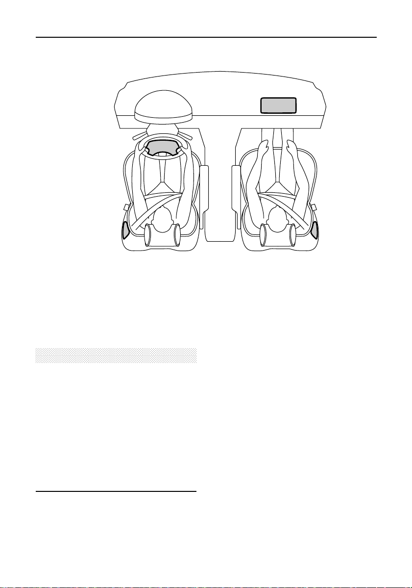
PO421
SRS/Airbag
This Range Rover is equipped with an airbag
SRS (supplementary restraint system) that
incorporates front and side airbags and a
lap/shoulder belt with pre-tensioners (see
’Seat belts’) at both the driver and front seat
passenger positions.
WARNING
The SRS/Airbags are a supplementary
restraint system that provides ADDITIONAL
protection in certain types of front and side
impact collisions only - they DO NOT replace
the need to wear a seat belt. To minimize
the risk of severe injury or death in the event
of a crash, all occupants in all seating
positions including the driver should always
use their seat belt (regardless of whether an
airbag is included at that seating position).
Provided the front seat occupants are
correctly seated with seat belts properly worn,
the airbags are a supplementary restraint
system that provides additional protection to
the chest and facial areas in the event of the
vehicle receivinga severe frontal impact, and
to the side of the body facing the impact, if a
severe side collision occurs.
The front airbags are located in the centre pad
of the steering wheel and in the fascia panel
above the glovebox. Side airbags are
positioned in the backrest padding on the
outward side of both front seats (see
illustration).
58
Page 61

SRS/Airbag
WARNING
Following inflation, some SRS/airbag
components are hot - DO NOT touch until
they have cooled.
Even with SRS/airbag equipment fitted, seat
belts must ALWAYS be worn because:
• An airbag will only provide additional
protection in certain types of front and
side collisions. NO protection is afforded
against the effects of rear impacts, roll
over accidents, or minor frontal impacts.
• Inflation and deflation take place
instantaneously and will not provide
protection against the effects of
secondary impacts that can occur during
multiple vehicle collisions.
WARNING
The airbag module inflates with
considerable speed and force. For your
safety:
An inflating airbag can cause facial
abrasions and other injuries. The injurious
effects of airbag inflation can be minimised
by ensuring driver and passenger are seated
correctly, with the seat moved back as far as
is practical, and the seat belts worn
correctly.
NEVER attach accessory items to an airbag
module cover, or place items of hand
luggage or any objects on the top of a
module cover; these could interfere with the
inflation of the airbag, or if the airbag
inflates, be propelled inside the vehicle
causing injury to the occupants.
DO NOT allow occupants to obstruct the
operation of the airbag modules by placing
their feet, knees or any part of their person
in contact with, or close to, an airbag
module whilst the vehicle is moving.
Activation of an airbag creates dust, causing
possible breathing difficulties for asthma
sufferers or other people with respiratory
problems. If an airbag is activated, any
occupant who suffers from breathing
difficulties should; either leave the vehicle
as quickly as possible, or obtain fresh air by
fully opening the windows or doors.
Both front seating positions are equipped
with knee bolsters to provide knee
protection in the event of an impact. DO NOT
modify the bolsters, or mount after market
equipment on or behind them.
59
Page 62

SRS/Airbag
To ensure correct deployment of the airbags,
it is essential that obstructions are not allowed
to intervene between an airbag and the
occupant. The following are examples of the
type of obstructions that could either, impede
correct operation of the airbags, or jeopardise
personal safety in the event of an airbag
deployment:
• Accessoriesattachedto an airbag cover.
• Items of hand luggage or other objects
placed on an airbag cover.
• Feet, knees or any other part of the
anatomy in contact with, or in close
proximity to, a front airbag cover.
• Head, arms or any part of the anatomy in
contact with, or in close proximity to, a
side airbag.
• Items of clothing or cushions draped over
the part of a front seat containing the
airbag.
• The use of seat covers that are not
approved for seats equipped with side
airbags will REDUCE or ELIMINATE the
effectivenessof the side airbags in the
event of a crash (in particular,be aware
that seat covers approved for use with
Range Rover vehicles prior to the
introduction of side airbags will NOT be
suitable for vehicles equipped with side
airbags! If in doubt, seek advice from a
Land Rover retailer).
How the airbag SRS works
In the event of a collision, the airbag control
unit monitors the rate of deceleration induced
by the collision to determine whether the
airbags should be deployed.
In the case of a severe frontal collision, both
front airbags will be deployed. In the case of a
severe side collision, only the airbag on the
impact side of the vehicle will inflate.
However, there may also be impact conditions
whereby one side and both front airbags
deploy at the same time, or where front and
side airbags respond separately as a result of
a secondary impact occurring after the initial
collision has taken place.
P0405
60
Page 63

SRS/Airbag
P0406
Airbag inflation is virtually instantaneous and
occurs with considerable force accompanied
by a loud noise. The inflated airbag, together
with the seat belt restraint system, limit the
occupant’s movement, thereby reducing the
risk of injury to the head and upper torso.
When an airbag inflates, a fine powder is
released. This is not an indicationof a
malfunction, however the powder may cause
irritation to the skin and should be thoroughly
flushed from the eyes and any cuts or
abrasions of the skin. After inflation, an airbag
deflates immediately. This provides a gradual
cushioning effect for the occupant and also
ensures that the driver’s forward vision is not
impaired.
IMPORTANT INFORMATION
The airbag SRS is not designed to
operate as a result of rear collisions,
minor frontal or minor side impacts, or if
the vehicle overturns; nor will it operate
as a result of heavy braking or driving
over bumps and potholes.
Operation of the airbag SRS is dependent
entirely on the acceleration or
decelerationforces that are applied to the
vehicle’spassengercompartmentas a
result of a collision. The circumstances
affecting different collisions (vehicle
speed, angle of impact, type and size of
object hit for example), vary considerably
and will affect the rate of acceleration or
decelerationaccordingly.
It follows, therefore, that in some
instances, significant superficialdamage
can occur to the vehiclewithout the
airbags deploying and, conversely, that in
other circumstances, the airbags will
deploy even though the vehiclehas
experiencedrelativelysmallamounts of
damage. However, if as a result of an
impact, you suspect that the airbags
should have deployed and have failed to
do so, please call
advice or to arrange for a Land Rover
representativeto inspect the vehicle to
verify that the airbag/SRS system
operated correctly.
1 (800) 637-6837 for
WARNING
Following inflation, some airbag SRS
components are hot - too avoid burns DO
NOT touch until they have cooled.
61
Page 64

SRS/Airbag
Side airbags
Side airbags are designed to protect the
thorax region of the torso and will only deploy
in the event of a severe side impact. They will
NOT inflate as a result of frontal or rear
impacts.
In the event of a severe side collision, the
airbag on the impact side of the vehicle breaks
through the seat covering, rapidly inflating to
form a cushion between the occupant and the
side of the vehicle.
Note that a part of the outer side of the seat
trim (identified by the woven ’airbag’label)is
manufactured with a specially constructed
seam which enables the airbag to break
through. The manufacture and materials of the
seat are critical to the performance of the
airbag. For this reason, non-approved seat
covers must NEVER be fitted, and it is
recommended that any repair or replacement
to the front seats be carried out by a Land
Rover retailer (see ’Service information’).
Airbag SRS warning light
Whenever the starter switch is turned to
position ’II’, the diagnostic control unit
monitors the readiness of the system’s
electricalcircuits.The elements of the system
being monitored include:
• SRS warning light
• Rotary coupler
• Airbag modules
• Seatbelt pre-tensioners
• Airbag diagnostic control unit
• Front crash sensors
• Airbag wiring harnesses
A warning light, mounted on the instrument
pack, will alert you to any malfunction which
might prevent the airbag SRS from operating
correctly in the event of an impact. The
system should always be checked by a retailer
if any of the following symptoms occur:
• The warning light fails to illuminate when
the starter switch is turned to position ’II’.
• The warning light fails to extinguish within
approximatelyfive seconds after the
starter switch is turned to position ’II’.
• The warning light illuminates whilst the
vehicle is being driven.
NOTE: After the starter switch is turned to
position ’II’, the system’s diagnostic control
unit checks its own memory and the warning
light bulb for faults. If a fault is found, the
warning light will illuminate.
Seating positions
In order to provide optimum protection in the
event of a severe vehicle impact, it is
necessaryfor the airbags to deploy with
considerablespeed.
An inflating airbag can cause facial abrasions
and other injuries if the occupant is too close
to the airbag at the time of its deployment.
WARNING
To minimise the risk of accidental injury
from inflating airbags, seat belts should be
correctly worn at all times. In addition, both
driver and front seat passenger should
adjust the seat to provide the maximum
practical distance from the front airbags,
and also ensure that a gap is maintained
between the upper torso and the side of the
vehicle to enable unobstructed inflation of
the side airbags.
62
Page 65

SRS/Airbag
CHILD SEATS
Children aged 12 years and under are more
likely to receive injuries from inflating airbags
than adult occupants. For this reason, it is
recommended that children should always be
seated in the rear of the vehicle in a child
safety seat or restraint system appropriate to
their age and size (see ’Seat belts’).
However, if it is necessary for a child to travel
in the front, set the seat fully rearwards and
use a front facing child seat ONLY.
WARNING
DO NOT USE A REAR FACING CHILD SEAT IN
ANY FRONT SEAT LOCATION. If the
passenger airbag inflates, it could impact
with the child restraint causing serious
injury or death to the child.
Children could be endangered in a crash if
their child restraints are not properly
secured in the vehicle. Be sure to install
child restraints according to the
manufacturer’s instructions.
Under no circumstances should a rear facing
child seat be installed facing forward in any
seating position.
Service information
Certain components of the SRS/airbag must
be replaced by a Land Rover retailer after 10
years for front airbags, and 15 years for side
airbags from the date of manufacture (shown
on the certification plate attached to the lock
face of the front left-hand door).
In addition, ALWAYS contact your retailerif:
• an airbag inflates.
• the front or side of the vehicle is damaged,
even if the corresponding airbag has not
inflated.
• any part of an airbag module cover shows
signs of deterioration or damage.
WARNING
DO NOT attempt to service repair, replace,
modify or tamper with any part of the airbag
SRS, or wiring in the vicinity of an airbag
SRS component; this could cause the
system to activate, resulting in personal
injury.
63
Page 66

SRS/Airbag
WARNING
The components that make up the
SRS/airbag are sensitive to electrical or
physical interference, either of which could
easily damage the system and cause
inadvertent operation or a malfunction of the
airbag module.
To prevent any SRS/airbag malfunction,
ALWAYS consult a Land Rover retailer
before fitting any of the following.
• Electronic equipment such as a mobile
phone, two-way radio or in-car
entertainment system.
• Accessories attached to the front or side
of the vehicle such as a winch or
brushbar.
• Any modification to the front or side of
the vehicle including the bumper or
chassis.
• Any modification involving the removal
or repair of any wiring or component in
the vicinity of any of the SRS
components (yellow wiring harness),
including: the steering wheel, steering
column, front seats, instrument and
fascia panels.
• Any modification to the fascia panels,
steering wheel or front seats.
Disposing of vehicles
If you sell your vehicle,be sure to inform the
new owner that the vehiclehas an airbag SRS,
and make the new owner aware that certain
components of the system will need renewing
after either 10 years (front airbag) or 15 years
(side airbag).
If the vehicle is to be scrapped: uninflated
airbags are potentially very dangerous and
must be safely deployed in a controlled
environment by qualified personnel BEFORE a
vehicle is scrapped.
WARNING
Only use Land Rover approved seat covers
for use with seats fitted with side airbag
modules. The use of non-approved seat
covers will REDUCE the effectiveness of the
side airbags in the event of a crash
condition.
64
Page 67

Steering column
STEERING COLUMN ADJUSTMENT
Adjust the angle and height of the steering
column to suit your driving position:
1. Fully withdraw the lever and then pull it
towards the steering wheel rim.
2. Keeping the lever in this position, tilt the
steering column up or down to the
required angle and pull or push to extend
or retract the steering wheel.
3. Release the lever to lock the column in
position once a comfortable driving
position has been achieved.
WARNING
DO NOT attempt to adjust the steering
column whilst the vehicle is in motion. This
is extremely dangerous and may result in
the loss of control of the vehicle and
personal injury.
65
Page 68

Door mirrors
ELECTRICALLY-OPERATED DOOR MIRRORS
1. Slide the switch left or right to select the
appropriate mirror.
2. With the starter switch turned to position
’I’ or ’II’, press the appropriate side of the
rocker switch to tilt the mirror glass
up/down or left/right.
Automatic dipping for reverse gear selection
The mirror memory has a pre-storedfunction
which causes the mirrors to dip automatically
whenever reverse gear is selected. If
necessarythe ’dipped’ mirror positions can be
altered as follows:
1. Turn the starter switch to position ’I’ or ’II’
(do not start the engine).
2. Select reverse gear.
3. Adjust either or both mirrors to the
desired positions.
4. Press the seat MEMORY STORE switch
together with either switch 1 or 2
(whichever correspondswith the driver’s
seat memory) for 2 seconds (the message
centre displays ’MIRROR DIP STORE’).
NOTE: The right-hand exteriordriving mirror
is convex and objects in this mirror are closer
than they appear.
NOTE: The mirror positions can be set in
conjunction with the driver’s seat positions
(see ’Seats’).
NOTE: Door mirrors have integral heating
elements which disperse ice or mist from the
glass. This function operates continuously
whilst the engine is running.
66
Page 69

Door mirrors
To disable the dip function:
Turn the starter switch to position ’I’ or ’II’ (do
not start the engine) and select reverse gear.
Press and hold the seat MEMORY STORE
switch for 2 seconds, the message centre
displays ’MIRROR DIP OFF’ and a tone
sounds.
To restore the dip function:
Turn the starter switch to position ’I’ or ’II’ (do
not start the engine), and select reverse gear.
Press and hold the MEMORY STORE switch
for 2 seconds and the message centre briefly
displays the message ’MIRROR DIP ON’
(returning the mirrors to either the factory or
your own pre-set positions).
NOTE: The mirror dip function can be
individuallydisabledor restored for each seat
memory position (1 and 2). Select the
appropriate memory position before disabling
or restoring the function.
Manual adjustment
Each door mirror assembly can be moved
through four positions.
The fully forward and rearward positions,
enable the mirror body to fold almost flat
against the side of the vehicle and are useful
for negotiating narrow openings. The two
intermediate positions, enable the mirror body
to be adjusted to suit the differing
requirements of either the passenger or
driver’s side of the vehicle - the forward
intermediate position should be used for the
driver’s side, and the rearward intermediate
position used for the passenger side.
67
Page 70

Instruments
1. Tachometer
Indicates engine speed in revolutions per
minute.
Your vehicle is fitted with a system which
automaticallyrestrictsthe number of
revolutions per minute once the engine’s
maximum ’governed’ speed has been reached.
Engine speed restriction limit: 5,500 rpm
2. Speedometer
Indicates road speed in miles and/or
kilometres per hour.
3. Total distance recorder
Indicates the total distance travelled by the
vehicle. (Turn the starter switch to position II
to illuminate display).
4. Trip recorder (trip 1)
Records individual journey distances (see also
’Trip computer’). (Turn the starter switch to
position II to illuminate display).
5. Trip recorder reset button (trip 1)
Press to return the trip recorder to zero.
CAUTION
DO NOT attempt to open the instrument pack
or change the instrument bulbs - warranty
cover may be invalid if the pack has been
tampered with.
68
Page 71

Instruments
6. Temperature gauge
Once the engine coolant has reachedits
normal operating temperature, the pointer
should be almost vertical (the precise position
will vary depending on the ambient
temperature). If the pointer moves towards
the RED segment, a RED warning light in the
temperature gauge illuminates. Should the
pointer move INTO the red segment, stop the
vehicle as soon as safety permits and seek
qualified assistancebefore continuing.
7. Fuel gauge
The pointer drops to zero when the starter
switch is turned off, but quickly rises to show
the level of fuel in the tank when the switch is
turned to position ’II’. After refuelling, the
gauge rapidly changes to reflect the increase
of fuel in the tank.
An arrow on the fuel gauge indicates on which
side of the vehicle the fuel filler flap is located.
NOTE: The gauge may not indicate fuel level
increasesof 4 US gallons (15 litres) or less.
When the fuel remaining in the tank is a
minimum of 2.4 US gallons (9 litres), the
AMBER warning light will illuminate. If the
light illuminates, refuel at the first opportunity.
Fuel tank capacity is approximately 25 usable
US gallons (93 litres).
CAUTION
NEVER allow your vehicle to run out of fuel
(the resultant misfire may destroy the
catalytic converter).
69
Page 72

Warning lights
Some warning lights may also be
accompanied by a message which will appear
in the message centre display on the
instrument pack. (see ’Message centre’ for
details).
The warning lights are colour coded as
follows:
GREEN & BLUE lights indicate that a unit is
operating.
AMBER & YELLOW lights are cautions.
RED lights are warnings.
IMPORTANT INFORMATION
RED warning lights are particularly
important, illumination indicates that a
serious fault exists. If a red warning light
illuminates, always stop the vehicle and
review the specific instructions relating to
that warning light contained in this
section of the manual.
Parking brake/brake system RED.
Illuminates for 3 seconds as a
bulb check when the starterswitch is turned
to position ’II’ and also illuminates when the
parking brake is applied and the starter switch
is in position ’II’.
The light should extinguish when the parking
brake is fully released or after the bulb check if
the parking brake is off. If the light illuminates
whilst driving, a fault is indicated.Stop the
vehicle as soon as safety permits and seek
qualified assistancebefore continuing.
NOTE: If the vehicle has been standing for
some time, it may take up to 40 seconds
before the light extinguishes (in this case, ABS
and TC warning lights will also be
illuminated).
70
Page 73

Warning lights
Seatbelt - RED.
The light illuminates for 6
seconds when the starter switch
is turned to position ’II’. ALWAYS fasten your
seat belt BEFORE driving.
Battery charging - RED.
Illuminates as a bulb check when
the starter switch is turned to
position ’II’ and extinguishes when the engine
is running. If it remains on, or illuminates
when driving, a fault is indicated. Seek
qualified assistanceurgently.
Trailer direction indicators -
GREEN.
This light is only operative when
a trailer is connected to the vehicle via a
multi-pin socket. The light flashes in
conjunction with the vehicle direction
indicators, thus confirming that the trailer
indicator lights are operating correctly. In the
event of the failure of a trailer direction
indicator light, the warning light will not
illuminate.
Low engine oil pressure - RED.
Illuminates as a bulb check when
the starter switch is turned to
position ’II’, and extinguishes when the engine
is running. If it remains on when the engine is
started, or comes on during a journey, stop
the vehicle as soon as safety permits and seek
qualified assistancebefore continuing. Always
check the oil level when this light illuminates.
NOTE: At very low ambient temperatures, the
light may take several seconds to extinguish.
Transfer gearbox - AMBER.
The light starts flashing when the
selector lever is moved across
the ’H-gate’, and continues flashing until the
transfer gearbox has completed a change
from one range of gears to another.
DO NOT release the brakes or move the
selector lever out of ’N’ into one of the drive
positions until the light stops flashing.
ABS - YELLOW.
This light illuminates for
approximately1 second when the
starter switch is turned to position ’II’, and
then briefly extinguishes before coming on
again. The warning light will then remain
illuminated until the vehicle is driven above
approximately5 mph (7 km/h). If the light
does not extinguish and then illuminate again,
then a fault has occurred with the ABS system
and you should consult your Land Rover
retailer at the earliest opportunity.
If the light remains illuminated once a speed
of 5 mph (7km/h) has been reached, or
subsequently illuminateswhilst driving, a fault
has been detected by the self-monitoring
system. The message centre will display ’ABS
FAULT’; this means that full ABS control may
not be available, and you should consult your
retailer at the earliest opportunity.
Airbag SRS - RED.
The light illuminates when the
starter switch is turned to
position ’II’, and extinguishes after
approximately8 seconds. If the light
illuminates at any other time, a fault is
indicated (see ’Airbag SRS’). Seek qualified
assistanceurgently.
71
Page 74

Warning lights
Traction control (TC) - AMBER.
Illuminates for three seconds
after the starter switch is turned
on and the ABS and traction control systems
have completed their self-checks.
Whilst driving, the TC light will illuminate (for
a minimum of two seconds), whenever
traction control is active; the light
extinguishing as soon as traction control
ceases. The light flashing (for at least ten
seconds), indicates that the system has been
over-used; it will be available again once the
system components have cooled.
If the light illuminates continuously, a fault
with the system is indicated; seek qualified
assistance.
Direction indicators - GREEN.
The left or right warning light
flashes in time with the
corresponding left or right direction
indicators, whenever they are operated. A
warning light flashing at twice the normal
speed, indicates that a direction indicator bulb
has failed (the message centre will indicate
which bulb is faulty). If a trailer is connected
and a rear indicator bulb fails, then the
message will not be displayed. When the
hazard switch is pressed, both warning lights
will illuminate in conjunction with the indicator
lights.
Headlight high beam - BLUE.
This light illuminates whenever
the high beam headlights are on.
Lights on - GREEN.
This light illuminates when the
sidelights and/or headlights are
switched on. It will not illuminate when
parking lights or headlight delay are in
operation.
Air suspension - AMBER.
Illuminates as a bulb check when
the starter switch is turned on
and remains illuminated until two seconds
after the engine has started.
In addition, the light will illuminate whilst
driving whenever ’High’ or ’Extended’ ride
heights are selected, and also if a fault with
the air suspension system is detected.
72
Page 75

Warning lights
Service Engine Soon - AMBER.
The engine management system
on your Land Rover is controlled
by a sophisticated engine control module
which maintains optimum control of engine
running and emission levels and monitors the
operation of the sub-systems and
components.
The ’Service Engine Soon’ indicator
illuminates as a system check when the starter
switch is turned to position ’II’ and should
extinguish when the engine is started.
If an engine operation or emissions problem
is registered by the engine control module
when the vehicle is being operated, the
’Service Engine Soon’ indicator will illuminate.
If ’Service Engine Soon’ illuminates, and the
vehicle drives normally:
Contact your Land Rover retailer to schedule a
service appointment at your earliest
convenience - YOU MAY STILL DRIVE THE
VEHICLE.
NOTE: An incorrectlyfittedfuel filler cap may
cause the ’Service Engine Soon’ warning light
to illuminate.
If ’Service Engine Soon’ flashes and/or the
vehicle does not drive normally:
Avoid high speeds and seek immediate
assistancefrom your Land Rover retailer.
AUDIBLE WARNINGS
Starter key warning.
An audible warning sounds if the key is
left in the starter switch when the driver’s
door is opened, if the engine is not
running. It will cease, as soon as the key
is removed or the driver’s door is closed.
This is accompanied by the message
centre displaying ’IGNITION KEY IN’.
Lights on warning.
An audible warning (3 beeps) sounds if
the driver’s door is opened whilst the
headlights or park lights are turned on
and after the key is removed from the
starter switch. It will cease as soon as the
lights are switched off, or when the
driver’s door is closed. The warning is
accompanied by the message centre
displaying ’LIGHTS ON’ or ’PARK
LIGHTS’.
Driver’s seat belt reminder.
A continuous audible warning sounds
and the message centre displays ’SEAT
BELT PLEASE’ for a 6 second period, or
until the seat belt is latched.
High/low range change warning
An audible warning will sound whilst a
change from one gear range to another is
attempted. The warning will cease, once
the change is complete or cancelled.
73
Page 76

Lights & indicators
DIRECTION INDICATORS
Move the lever DOWN to indicatea LEFT turn,
and UP to indicate a RIGHT turn. The
appropriate GREEN warning light on the
instrument panel will flash in time with the
direction indicators.
Hold the lever part-way up or down against
spring pressure to indicate a lane change.
LIGHTING SWITCH
Side, tail and instrument panel
lights
Insert the starter key and turn the
lighting switch to position ’1’.
Headlights
Turn the lighting switch to
position ’2’.
Headlight courtesy delay
To illuminate the drive way after leaving the
vehicle, the headlight courtesy delay can be
operated, as follows:
1. Turn the lighting selector switch to
position ’2’ and the starter switch to
position ’II’.
2. Turn the starter switch back to position
’0’, remove the key, and turn the lighting
switch from position ’2’ to ’0’.
3. The headlights will remain on for
approximately25 seconds and the
message centre will display ’HEADLIGHT
DELAY’.
74
Page 77

Lights & indicators
Headlight main and dipped beams
Pull the lever fully towards the steering wheel
to change from dipped beam to main beam
(BLUE warning light on the instrument panel
glows when the headlights are on main
beam).
To flash the headlights, pull the lever part-way
toward the steering wheel (to the first
position) and release.
Parking lights
With the lighting switch in position ’1’ and the
starter key removed, move the direction
indicator lever fully DOWN to illuminate the
left hand side and tail lights, or UP to
illuminate the right hand side and tail lights
(lights on both sides will remain on if the lever
is in its CENTRAL position). To switch off,
turn the lighting switch to position ’0’.
Daylight running lights
(Canada only)
With the lighting switch off, the daylight
running light system illuminates the headlight
low beams, as soon as engine speed exceeds
500 rpm. The instrument panel illumination
remains off.
The daytime running lights will extinguish
when the parking brake is applied and also
when ’P’ (park) is selected.
Instrument dimmer control
Rotate the rocker switch to the left or right to
reduce or increase the intensity of instrument
panel illumination. The dimmer also controls
the illumination level of switches and (where
fitted) the intensity of the air conditioning LCD
display.
The instrument dimmer also controls the
intensity of the message centre display.
However, note that if the illumination level is
set to its maximum (rotate rocker switch to
the right and hold), then a momentary press
of the rocker switch to the left will dim the
message centre display, but leave the
instrument illumination at maximum.
NOTE: If the side lights are switched on when
a driver’s seat position is stored in the seat
memory, then the illumination level of the
instrument panel will be stored at the same
time.
75
Page 78

Wipers & washers
WINDSCREEN WIPERS
The windscreen wipers will only operate when
the starter switch is turned to position ’I’ or
’II’.
IMPORTANT INFORMATION
Do not operate the wipers on a dry
screen.
To prevent possible overload damage to
the linkage or the wiper motors, in either
freezing or extremely hot conditions, care
must be taken to ensure that the wiper
blades are not adhering to the glass
before operating the wipers.
In winter, remove any snow or ice from
around the arms and blades, including
the wiped area of the windscreen and the
heater air intakes.
FRONT SCREEN
To operate the front screen wipers only, the
lever must be pushed away from the steering
wheel.
Single wipe
Raise the lever to position ’1’ and release.
Intermittent wipe
Lower the lever to position ’2’ to engage
intermittent wipe. Rotate the thumb wheel left
or right, to reduce or increase the delay
between wipes.
Normal/fast speed wipe
Lower the lever to position ’3’ for normal, and
to position ’4’ for fast, continuous wipe speed.
76
Page 79

Wipers & washers
REAR SCREEN
Pull the lever towards the steeringwheel for
rear screen intermittent wipe.
All front wiper functions are also availablein
this position, using the four positions
described on the previous page.
If the front wipers are operating in intermittent
mode, then the rear wiper will wipe on every
second operation of the front wipers. If the
front wipers are operating in continuous
mode, then the thumbwheel controls the delay
of the rear wiper.
WINDSCREEN WASHER
Front screen wash/wipe
Press and hold the lower button to operate the
front screen wash/wipe. The washers will
continue operating for as long as the button is
pressed. After releasing the button, the wipers
will complete 3 full wipes before either
parking or continuing with any other selected
wiper function.
A momentary press on the lower button, will
initiate a programmed wash/wipe. The
washers will operate briefly and then stop
automatically,the wipers then completing 3
full wipes before either parking or continuing
with another function. Moving the lever to any
other front wipe position during the
programmed wash/wipe, will cancel the
remainder of the programme.
NOTE: If the wiper system senses a low fluid
level in the washer reservoir, then the
programmed wash/wipe will only operate for
as long as the button is pressed, i.e. there will
be no timed wash and no additional 3 wipes.
77
Page 80

Wipers & washers
Washer jets
To adjust the front screen washer jets, insert a
needle into the jet orifice and use it to position
the jet so that the spray is directed towards
the horizontal centre line of the windscreen.
If the jets become obstructed, a needle or
strand of wire can be used to clear the
blockage.
Rear screen wash/wipe
Press and hold the upper button to operate
the rear screen wash/wipe. The washer will
continue operating for as long as the button is
pressed. After releasing the button, the wiper
will complete 3 full wipes before either
parking or continuing with any other selected
function.
A momentary press on the upper button will
initiate a programmed wash/wipe. The washer
will operate briefly and then stop
automatically,the wiper then completing 3 full
wipes before either parking or continuing with
another function. Moving the lever to any
other rear wipe position during the
programmed wash/wipe will cancel the
remainder of the programme.
The rear wiper will operate automatically
whenever reverse gear is selected, provided
the front screen wipers are operating in either
intermittent, or continuous mode.
HEADLIGHT WASH/WIPE
Headlight wash/wipe is controlled by a timer
unit, and operates automatically on every
second wash of the front screenwash system
when the headlights are switched on.
NOTE: If the wiper system registers a low
screen wash fluid level the headlight
wash/wipe will not operate at all.
LOW SCREEN WASH FLUID
When the screen wash level is low, the
message centre displays ’LOW SCREEN
WASH’. The message appears whenever the
front or rear wash/wipe systems are used and
is also activated whenever the starter switch is
turned to, or from, position ’II’. To reset the
system, the reservoir must be filled when the
starter switch is turned off (see ’Windscreen
washer top-up’).
78
Page 81

Switches
DASHBOARD CENTRE CONSOLE SWITCHES
The following switches are located on the
centre console between the driver and front
seat passenger:
Front fog lights
Press to switch on and off; the
switch illuminates whilst the
lights are switched on.
The lights operate only with the starter switch
in position ’II’ and the headlights switched on
(low beam only). Note that the fog lights
extinguish automaticallyif the headlights are
changed to main beam, and will have to be
re-selectedif the headlights or the starter
switch have been turned off.
DO remember to switch off as soon as
visibilityis clear.
Rear fog guard lights
Press to switch on and off; the
switch illuminates whilst the
lights are switched on. The rear fog guard
lights will operate only when the starter switch
is in position ’II’, and when the headlights are
switched on.
Note that the fog guard lights will have to be
reselectedif the headlights have been turned
off.
REMEMBER: In clear conditions rear fog
guard lights can dazzle other road users. Use
only when visibility is severely restricted;
Hazard warning lights
Press to operate; all the direction
indicators, including those fitted
to a trailer, will flash in conjunction with each
other.
Use ONLY in an emergency to warn other
road users when your stationary vehicle is
causing an obstruction, or is in a hazardous
situation. Remember to switch off before
moving away.
NOTE: The functions of the electronic air
suspension system switches are described
under ’Air suspension’. The cruise control
master switch is described under ’Cruise
control.’
79
Page 82

Switches
STEERING WHEEL SWITCHES
The following switches are located on the
steering wheel:
Cruise control
The functions of the cruise control switches
’SET+’ and ’RES’ are described under ’Cruise
control’.
Mode switch
Press the MODE switch to select
either: radio, tape, or CD player
(see ’In-car entertainment’).
Seek/search forward
Press to select the NEXT station
on the selected waveband. When
tape or CD player are being used, seek/search
is used to select the next track.
Seek/search backward
Press to select the PREVIOUS
station on the selected
waveband. When tape or CD player are being
used, seek/search is used to select the
previous track.
Volume up
Press the positive switch to
increase the volume.
Volume down
Press the negative switch to
decrease the volume.
Horn
To operate the horn press one of the horn
symbols on the edge of the steering wheel
pad.
80
Page 83

Electric windows
The switches on the centre console operate
the following windows:
1. Right hand front window.
2. Left hand front window.
3. Right hand rear window.
4. Left hand rear window.
5. Switch to isolate rear door window
switches (when carrying children).
NOTE: Rear windows can also be operated by
individual window switches mounted on each
rear door, provided the isolation switch is not
activated.
Operating the windows
The electric windows can be operated when
the starter switch is in position ’I’ or ’II’ and
for up to 45 seconds after the starter switch is
turned off (provided neither front door is
opened in the meantime).
NOTE: Only manual mode (not ’one-touch’)is
availablefor the 45 second period(s).
Press and hold the lower part of a switch to
lower and the upper part to raise the window.
The window will stop moving as soon as the
switch is released.
WARNING
Accidental closing of a window on fingers,
hands or any vulnerable part of the body,
can result in serious personal injury.
Always observe the following precautions:
• ISOLATE the rear window switches when
carrying children.
• ENSURE children are kept clear when
raising or lowering a window.
• NEVER leave children alone in the
vehicle as this could result in serious
injury or death.
• ENSURE that all adult passengers are
fully familiar with the controls and the
potential dangers of
electrically-operated windows.
• ENSURE the ’anti-trap’ function is
activated (see next page).
81
Page 84

Electric windows
’One-touch’ up & down
By briefly pressing and then releasing a switch
1
(within
/2second), a window can be opened
or closed at a single touch. Window
movement can be stopped at any time by
pressing the opposing side of the switch.
’Anti-trap’ function
The ’anti-trap’ function is a safety feature
which prevents a window from closing when
an obstruction is sensed (’WINDOW
BLOCKED’ appears in the message centre). It
is recommended that this is set at all times,
but particularly when carrying children.
NOTE: If the ’one-touch’ and ’anti-trap’
functions have not been set, an audible
warning sounds and ’WINDOW NOT SET’ is
displayed in the message centre whenever a
window is closed and also whenever the
starter switch is turned on or off.
Setting the ’one-touch’ & ’anti-trap’
functions
If the battery has been disconnected, it will be
necessaryto reset the ’one-touch’ and
’anti-trap’ functions on each window, using
the following procedure:
1. FULLY open and close each window in
one continuous operation (note that as the
window is closing, an audible warning
sounds and ’WINDOW NOT SET’ is
displayed in the message centre).
2. Once the window has been fully opened
and closed, an audible warning sounds
and ’WINDOW SET’ (together with a
window identifier message) is displayed in
the message centre.
The ’one-touch’ and ’anti-trap’ functions will
now be operational.
NOTE: The ’one-touch’ up function is
availableon front windows only.
82
Page 85

Electric windows
Overriding the ’anti-trap’ function
Under certain conditions, you may wish to
override the ’anti-trap’ function. If, for
example, you attempt to operate the windows
with the operating mechanism partially frozen,
the ’anti-trap’ function may falsely sense a
trap situation and fail to close the window
(always clear any ice from the window to
prevent overloading the operating
mechanism).
The ’anti-trap’ function can be overridden as
follows:
1. Using the centre console switches only,
press and hold the upper part of the
appropriate window operating switch
within 10 seconds of the window backing
off (after it has sensed a trap situation).
2. Continue to hold the switch until the
window is either closed or has reached the
desired position (note that as the window
is closing, an audible warning sounds and
’ANTI-TRAP OFF’ is displayed in the
message centre).
Rear window isolation switch
Press the bottom of the switch to isolate the
rear window controls (a tone will sound);
press the top of the switch to restore
independant control.
If the switch is operated when the starter
switch is turned off, the message centre will
inform the driver that a change in status of the
switch has occurred (either ’REAR WINDOWS
OFF’ or ’REAR WINDOWS ON’ will be
displayed). Refer to ’MISCELLANEOUS FAULT
MESSAGES’, page 30 for more information
about the messages.
WARNING
Always isolate the rear window switches
when carrying children.
NOTE: The ’anti-trap’ function will be
operational again, as soon as the window
operating switch is released.
83
Page 86

Electric sunroof
The sunroof can be operated when the starter
switch is in position ’I’ or ’II’ and for up to 45
seconds after the starter switch is turned off
(provided neither front door is opened in the
meantime).
NOTE: Only manual mode (not ’one-touch’)is
availablefor the 45 second period(s).
NOTE: The sunroof blind can be opened and
closed manually, but will retract automatically
when the sunroof is opened.
The sunroof opens and closes in two separate
phases as follows:
To TILT the roof:
With the sunroof closed, press and hold the
lower part of the switch, releasing when the
sunroof is at the desired angle. Press and hold
the upper part of the switch to close the
sunroof.
To OPEN the roof:
Press and hold the upper part of the switch,
releasing when the sunroof is in the desired
position. Press and hold the lower part of the
switch to close the sunroof.
WARNING
Accidental closing of a sunroof on fingers,
hands or any vulnerable part of the body,
can result in serious personal injury.
Always observe the following precautions:
• ENSURE that passengers are kept clear
when closing the sunroof.
• NEVER leave children alone in the
vehicle as this could result in serious
injury or death.
• ENSURE that all adult passengers are
fully familiar with the controls and the
potential dangers of operating an
electrically-operated sunroof.
• DO NOT allow passengers to extend any
part of their bodies through the sunroof
whilst the vehicle is moving.
• ENSURE the ’anti-trap’ function is
activated whenever possible.
• DO NOT operate the sunroof in freezing
conditions or when the roof panel is
covered with ice or snow.
84
Page 87

Electric sunroof
’One-touch’ operation
Briefly press and then release the upper part
of the switch (within
will open to a pre-set position which
minimises air turbulence (and noise) within
the vehicle. To fully open the sunroof, press
and release the switch for a second time.
Press and release the lower part of the switch
1
(within
/2second) to close the sunroof at a
single touch.
Sunroof movement can be stopped at any
time by pressing the opposing part of the
switch.
The ’anti-trap’ function is a safety feature
which prevents the sunroof from closing
when an obstruction is sensed (message
centre shows ’SUNROOF BLOCKED’). It is
recommended that this is set at all times, but
particularlywhen carrying children.
1
/2second): The sunroof
’Anti-trap’ function
NOTE: If the ’one-touch’ and ’anti-trap’
functions have not been set, an audible
warning sounds and ’SUNROOF NOT SET’ is
displayed in the message centre whenever the
sunroof is operational and also whenever the
starter switch is turned on or off.
Setting the ’one-touch’ & ’anti-trap’
functions
If the battery has been disconnected, it will be
necessaryto reset the ’one-touch’ and
’anti-trap’ functions using the following
procedure.
1. FULLY open and close and then FULLY tilt
and close the sunroof in one continuous
operation; an audible warning sounds, and
’SUNROOFNOT SET’ is displayed in the
message centre whilst the sunroof is in
motion.
2. Once this operation has been successfully
completed, an audible warning sounds
and ’SUNROOF SET’ is displayed in the
message centre.
The ’one-touch’ and ’anti-trap’ functions will
now be operational.
Overriding the ’anti-trap’ function
Under certain conditions you may wish to
override the ’anti-trap’ function. If, for
example, you attempt to operate the sunroof
with the operating mechanism partially frozen,
the ’anti-trap’ function may falsely sense a
trap situation and fail to close the sunroof (it
is recommended that you clear any ice from
the sunroof to prevent overloading the
operating mechanism).
The ’anti-trap’ function can be overridden as
follows:
1. Press and hold the appropriate(upper or
lower) part of the switch within 10
seconds of the sunroof backing off (after it
has sensed a trap situation).
2. Continue to hold the switch until the
sunroof is closed; an audible warning
sounds and ’ANTI-TRAP OFF’ and
’SUNROOF’are displayed in the message
centre.
The ’anti-trap’ function will be operational
again, as soon as the switch is released.
Leaving the vehicle
The message centre will show ’SUNROOF
OPEN’ if the starter key is removed and the
driver’s door opened with the sunroof still
open.
If you are leaving the vehicle ALWAYS close
the sunroof.
85
Page 88

Electric sunroof
If sunroof operation should fail, first check the
fuse and renew if necessary.
If necessary, the emergency operating key
(stowed in the glovebox) can be engaged in
the sunroof motor spindle and used to
manually turn the spindle clockwise to close
the sunroof (see illustration).
The spindle is accessible by prising the front
courtesy light unit from the headlining.
On completion of manual operation, the
spindle must be turned back one quarter of a
turn to re-engage the drive mechanism.
Emergency operation
86
Page 89

H4063
Heating & ventilating
SRS
The heating and ventilation system provides
fresh, heated or de-humidified air through air
vents at the windscreen, face and foot levels
and to the rear passengercompartment,
where shown in the illustration.
Face level vents
Push the thumbwheel down/up to open/close
the vent. Direct the airflow by moving the
slider in the centre of the vent. Fully opening
the driver’s outboard vent also opens the lap
cooler outlet.
To ensure best ventilation and minimum
noise, the vents should be fully open
whenever the air distribution control is set to
face level.
87
Page 90

Heating & ventilating
AUTOMATIC TEMPERATURE CONTROL (ATC)
Automatic temperature control consists of a
computer controlled heating and air
conditioning system. It is programmed to
reach and then maintain optimum levelsof
comfort within the vehicle, irrespective of all
but the most severe climatic conditions.
FULLY AUTOMATIC OPERATION
With the engine running, press the ’Auto’
button (3) (’Auto’ appears in the display) and
then press the rocker switches (1) either side
of the display (2) to adjust the temperature for
the corresponding side of the vehicle,until an
agreeable comfort level (about 21˚C or 70˚F is
recommended) is reached. ’HI’ or ’LO’ will
appear in the display when the
maximum/minimum temperatures are
selected, in which case the system will not
function automatically.
To change the temperature scale to either
Centigrade or Fahrenheit press the two
outermost air distribution buttons (4)
simultaneouslyfor approximately 4 seconds.
NOTE: The automatic temperaturecontrol
system will not achieve temperatures on the
passenger side of the vehicle that are more
than 11˚F (6˚C) greater or less than the
temperature set for the driver’s side.
For optimum comfort, ensure all the vents,
including those in the rear, are open and that
the slider in the centre of each vent is in its
central position.
NOTE: For ATC to function correctly, all
windows should be closed and the air intake
at the base of the windscreen must be free
from ice, snow, leaves or other debris.
WARNING
To reduce the risk of accidents caused by
poor visibility, always remove frost and
snow from all glass surfaces and clear snow
from hood and roof panels before driving.
88
Page 91

Heating & ventilating
Programmed defrost/demist
With the engine running, press
the ’PROG’ button to
clear frost or mist at the beginning of a
journey (indicator light illuminates and the
’PROG’ symbol appears in the display).
The ’programmed defrost’ facility
automaticallyactivatesthe following:
• The most efficient heater settings to clear
the windscreen and front side windows
• The heated rear screen - for a maximum of
16 minutes
• The heated windscreen - for a maximum
of 4 minutes
Press the button again to deactivate
’programmed defrost’ and restore the original
settings.
Recirculation
Press to recirculate air inside the
vehicle interior (indicator light
illuminates)- useful to prevent traffic fumes
from entering the passenger compartment.
Press again to cancel recirculation.
NOTE: Prolonged recirculation may cause the
windows to mist. If this happens, switch off
air recirculation immediately.
Air conditioning ’off’
Press to switch the air
conditioning off (indicator light
illuminates).With air conditioning off, the ATC
will function in a semi-automatic mode with
minimal disturbance to your comfort. When
the ATC can no longer achieve comfort
without assistance from the air conditioning,
the air conditioning indicator light will flash
for 10 seconds. Press again to restore the
previous air conditioning settings.
NOTE: In very humid conditions, slight
screen misting may be experienced when the
air conditioning system is turned on. This is a
natural occurrence on most automotive air
conditioning systems. It is not a fault; misting
will clear after a few seconds once the air
conditioning system is operating.
89
Page 92

Heating & ventilating
SEMI AUTOMATIC OPERATION
The system will operate in a semi automatic
mode (’Auto’ extinguishes from the display)
and the air distribution and blower controls
can be operated manually.
Full automatic mode can be restored by
pressing the ’Auto’ button again.
Air distribution
Press the appropriate button to direct air as
required (the corresponding indicator light
above the switch illuminates).
Air to face vents.
(To ensure best performance, the
face level vents must be open).
Air to face vents and foot outlets.
(To ensure best performance, the
face level vents must be open).
Air to foot outlets.
Air to foot outlets and windscreen
(recommended if mild misting of
the windscreen occurs when in ’Auto’ mode).
All air to windscreen and side
window outlets. Recommended
if heavy misting of the windscreen occurs.
Fan speed control
Turn clockwise to increase and
anti-clockwiseto decrease airflow
from the vents. Bars appear in the display, the
number of which increases or decreases with
increasing/decreasingfan speed.
OTHER FEATURES
Front and rear screen heaters
As well as being activated by
’Programmed defrost’, both front
and rear screen heaters can be
operated individually by pressing the
appropriate button (press again when no
longer required). The rear screen heater
switches off automatically after 16 minutes,
and the windscreen heater automatically
ceases after 4 minutes.
CAUTION
DO NOT stick labels over the heating
elements, and DO NOT scrape or use
abrasive materials, to clean the inside of
the rear window.
Heated front seats
Press to heat seats (indicator
light illuminates) - press again to
switch off.
Low temperature warning
If the outside temperature is
approximately37˚F or less, and
there is a possibility of ice, then a snowflake
symbol appears in the display.
External temperature
The external temperature is continuously
displayed in the lower part of the display.
Self diagnostics
The air conditioning system has
the ability to constantly diagnose
itself for faults. If a fault is detected, the
’handbook symbol’ appears in the display.
Contact your retailer for assistance.
90
Page 93

Interior equipment
COURTESY AND MAP READING LIGHTS
Manual operation
Press the appropriate switch to turn the lights
on - press a second time to turn off.
NOTE: The front courtesy light switch
(arrowed) will also operate the rear courtesy
lights.
Front
NOTE: If the rear courtesy lights or map
reading lights are left on after being manually
operated, they will NOT extinguish
automatically.
Automatic operation
The front and rear courtesylights illuminate
automaticallywhenevera door or tailgate is
opened, and remain illuminated for
approximately15 seconds after the doors and
tailgate are closed or until the starter switch is
turned on.
If a door or the tailgate remains open for ten
minutes or more, a ’time out’ function will
extinguish the courtesy lights in order to
prevent the battery from discharging.
To cancel automatic operation:
Press and hold the front courtesy light switch
(1) until a tone sounds and the message
centre displays ’INT LIGHTS OFF’.
Repeat the procedure to re-activate automatic
operation (a tone sounds and the message
centre displays ’INT LIGHTS ON’).
Rear
91
Page 94

Interior equipment
FRONT ASHTRAY
Press the leading edge of the ashtray lid to
open. The compartment contains the cigar
stubber, the ashtray and the cigar lighter.
REAR ASHTRAY
Press the cigarette symbol to open.
To empty the ashtray, open the lid and remove
the inner tray.
DO NOT use the ashtray for disposing of
waste paper or other combustible materials.
To empty the ashtray, lift the inner tray from
the surround.
DO NOT use the ashtray for disposing of
waste paper or other combustible materials.
CIGAR LIGHTER
The cigar lighter is located in the front ashtray
compartment.
With the starter switch turned to position ’I’ or
’II’, press the lighter in to heat up. When it has
reached the correct temperature it will partially
eject and can then be withdrawn for use.
ONLY hold the cigar lighter by the handle.
DO NOT plug accessories into the cigar lighter
socket unless they are approved by Land
Rover.
GLOVEBOX
Press the button to releasethe catches and
lower the lid.
The glovebox light illuminates automatically
when the lid is opened and the side lights are
on, and extinguishes when the lid is closed.
NOTE: The glovebox lock is operated with the
starter key. Turn the key a quarter turn to the
left to lock.
92
Page 95

Interior equipment
CUBBY BOX
Press the button (arrowed) and lift to open the
lid which can be rotated (see inset) to form a
cup holder. Press down on the front of the lid
to close and ensure that the latch has fully
engaged before using the lid as a cup holder.
H3057
AUXILIARY POWER SOCKET
CAUTION
NEVER plug unapproved accessories into the
auxiliary power socket. Damage to the
vehicle’s electrical systems could occur.
CD AUTOCHANGER
The CD autochanger is located in the rear
loadspace as shown.
Operation of the CD autochanger is covered
fully in the ’In-car entertainment’ book.
An electrical accessoriessocket is mounted in
the rear loadspace (where shown). This can
be used to power Land Rover approved
electricalaccessoriesthat use a maximum of
180 Watts.
NOTE: Always run the engine if prolonged
use of electrical accessories is required otherwise, the battery will become discharged.
93
Page 96

Interior equipment
H3569
H3062
INTERIOR REAR-VIEW MIRROR
The interior mirror is equipped with an
automatic dimming function that reduces
glare from following vehicles at night. The
dimming function is activated by the light
sensor (arrowed), which also dims the door
mirrors.
SUN VISOR VANITY MIRROR ILLUMINATION
With the starter switch turned to position ’II’,
pivot the sun visor downward and raise the
cover on the vanity mirror to illuminate the
mirror. Close the cover to extinguishthe
lights.
CLOCK
To adjust the time, press and release the
button to increment by one minute; press
continuously to ’fast forward’ the hands.
NOTE: The clock will need to be reset if the
battery has been disconnected.
94
Page 97

Interior equipment
LOADSPACE COVER
Fold the rear loadspace cover by pushing
upward and forward (arrowed) into the
vehicle. Lay the rear section of the cover on
the forward section.
WARNING
DO NOT carry luggage or loose items on the
loadspace cover - these may obscure vision
and could become dangerous projectiles in
the event of a sudden stop or collision.
All equipment, luggage or tools carried in
the load area should be secured to minimise
the risk of injury to the driver and
passengers in the event of an accident or
emergency manoeuvre.
The loadspace cover can be removed by
pulling on the rear to disengage it from the
side spigots and stored in the forward area of
the loadspace; a channel is formed in both of
the loadspace side panels immediately behind
the rear seats to accommodate the folded
loadspace cover.
95
Page 98

In-Car Telephones
NOTE: Refrain from operating a telephone
fitted with its own aerialinside the vehicle (see
main text).
Your vehicle utilises a number of electronic
systems designed to provide you with
maximum comfort, safety and economy.
These systems may be affected by the use of
mobile communication equipment inside the
vehicle. However, the use of an external aerial
will greatly reduce the likelihood of this
occurrence.
For your safety, always note the following
precautions before fitting or using an in-car
telephone, or any mobile communication
equipment.
• Only use an installation kit incorporating
an aerial external to the vehicle.
• Ensure that the installation is carried out
by a competent installer.
• Refrain from operating a mobile phone
fitted with its own aerialinside the vehicle
- the electromagnetic field radiated by the
phone may interfere with the vehicle’s
electricalsystems.
CAUTION
For your safety and that of others, using any
hand-held appliance whilst driving can be
dangerous. Always stop the vehicle before
making a call and ensure the telephone is
switched off whilst you are driving.
96
Page 99

Land Rover HomeLink®
HOMELINK TRANSMITTER*
The Land Rover HomeLink Universal
Transmitter provides a convenient way to
replace up to three hand-held transmitters
with a single built-in device. This innovative
feature will learn the radio frequency codes of
most current transmitters to operate garage
doors and gates. With the availableaccessory
package, the HomeLink Transmitter can also
control home or office lighting and security
systems. For reliability, the HomeLink
Transmitter is powered by your vehicle’s
battery and charging system.
Precautions
WARNING
Do not use this HomeLink Transmitter with
any garage door that lacks safety ’stop’ and
’reverse’ features, as required by federal
safety standard (this includes any garage or
door opener model manufactured before
April 1, 1982). A garage door opener which
cannot ’detect’ an object in the path of a
closing door and then automatically ’stop’
and ’reverse’ the door, does not meet
current federal safety standards. Using a
garage door opener without these features
increase the risk of serious injury or death.
For more information on this matter, call
toll-free: 1-800-355-3515.
CAUTION
When programming your HomeLink
Transmitter, you will be operating the
garage door or gate. Be sure that people
and objects are out of the way, to prevent
potential harm or damage.
Programming
3
2
1
3
2
1
HANDHELD
TRANSMITTER
H4062
If after repeated attempts you do not
successfullyprogram the HomeLink
Transmitter to learn the signal of the
hand-held transmitter, call toll-free for
customer assistance: 1-800-355-3515.
1. If you have previously programmed your
HomeLink Transmitter, proceed to step 2.
Otherwise, hold down the two outside
buttons on the HomeLink Transmitteruntil
the red light begins to flash. Release both
buttons.
2. Decide which one of the three channels
you want to program.
3. Hold the end of your hand-held transmitter
against the front surface of the HomeLink
Transmitter so that you can still see the
red light (see illustration).
97
Page 100

Land Rover HomeLink®
4. Using both hands, push the hand-held
transmitter button and the desired button
on the HomeLink Transmitter. Continue to
press both buttons through step 5.
5. Hold down both buttons until you see the
red light on the Land Rover HomeLink
Transmitter flash, first slowly and then
rapidly. It indicates that you have
successfullyprogrammedthe HomeLink
Transmitter to learn the new frequency
signal. Release both buttons once the
rapid flashing begins.
Operating the Land Rover HomeLink
Transmitter
Once it is programmed, the HomeLink
Transmitter can be used in place of your
hand-held transmitter(s).To operate, simply
press the appropriate button on the HomeLink
Transmitter. The red light comes on while the
signal is being transmitted.
NOTE: If your hand-held transmitter appears
to program the HomeLink Transmitter, but
does not open your garage door and, if your
garage door was manufactured after 1995,
your garage door opener may have a ’code
protected’ or ’rolling code’ feature.
A ’rolling code’ type of system will change the
’code’ of your garage door opener every time
you open or close your garage door.
To determine if you have one of these
systems, depress the button on your
HomeLink Transmitter that you programmed.
If the red light on the HomeLink Transmitter
flashes rapidly for 1-2 seconds, then turns
solid, your garage door opener has a rolling
code system.
Training a garage door opener equipped
with ’rolling codes’
To train your ’rolling code’ garage door
opener to operate from your HomeLink
Transmitter, follow these steps:
1. Program your hand-held transmitter to the
HomeLink Transmitter by following the
procedures outlined in ’Programming’, (if
you already completed this programming,
proceed to the next instruction).
2. Train your garage door opener receiver to
recognize your HomeLink Transmitter:
(your garage door opener receiver will
learn to recognize the HomeLink
Transmitter by following the same process
used to train the hand-held transmitter)
a) Remove the cover panel from your
garage door opener receiver (the receiver
should be located by the garage door
motor).
b) Locate the training button on the
garage door opener receiver. The exact
location and colour of the button may vary
by garage door opener brand. If you have
difficulty locating the training button,
reference your garage door opener
manual, or call 1-800-355-3515.
c) Press the training button on the garage
door opener receiver for 1-2 seconds.
d) Return to the HomeLink Transmitter in
the vehicle and depress the programmed
HomeLink Transmitter button for the
duration of the rapid flash of the
HomeLink’s red light, (1-2 seconds).
Release the button and depress the button
to confirm that the HomeLink Transmitter
has been trained to the receiver.
98
 Loading...